


ASUS P4SGL-MX User Manual

P4SGL-MX
User Guide
Motherboard

Checklist
E1 117
First Edition
November 2002
Copyright © 2002 ASUSTeK COMPUTER INC. All Rights Reserved.
No part of this manual, including the products and software described in it, may be
reproduced, transmitted, transcribed, stored in a retrieval system, or translated into any
language in any form or by any means, except documentation kept by the purchaser for
backup purposes, without the express written permission of ASUSTeK COMPUTER INC.
(“ASUS”).
Product warranty or service will not be extended if: (1) the product is repaired, modified or
altered, unless such repair, modification of alteration is authorized in writing by ASUS; or (2)
the serial number of the product is defaced or missing.
ASUS PROVIDES THIS MANUAL “AS IS” WITHOUT WARRANTY OF ANY KIND, EITHER
EXPRESS OR IMPLIED, INCLUDING BUT NOT LIMITED TO THE IMPLIED WARRANTIES
OR CONDITIONS OF MERCHANTABILITY OR FITNESS FOR A PARTICULAR PURPOSE.
IN NO EVENT SHALL ASUS, ITS DIRECTORS, OFFICERS, EMPLOYEES OR AGENTS BE
LIABLE FOR ANY INDIRECT, SPECIAL, INCIDENTAL, OR CONSEQUENTIAL DAMAGES
(INCLUDING DAMAGES FOR LOSS OF PROFITS, LOSS OF BUSINESS, LOSS OF USE
OR DATA, INTERRUPTION OF BUSINESS AND THE LIKE), EVEN IF ASUS HAS BEEN
ADVISED OF THE POSSIBILITY OF SUCH DAMAGES ARISING FROM ANY DEFECT OR
ERROR IN THIS MANUAL OR PRODUCT.
SPECIFICATIONS AND INFORMATION CONTAINED IN THIS MANUAL ARE FURNISHED
FOR INFORMATIONAL USE ONLY, AND ARE SUBJECT TO CHANGE AT ANY TIME
WITHOUT NOTICE, AND SHOULD NOT BE CONSTRUED AS A COMMITMENT BY ASUS.
ASUS ASSUMES NO RESPONSIBILITY OR LIABILITY FOR ANY ERRORS OR
INACCURACIES THAT MAY APPEAR IN THIS MANUAL, INCLUDING THE PRODUCTS
AND SOFTWARE DESCRIBED IN IT.
Products and corporate names appearing in this manual may or may not be registered
trademarks or copyrights of their respective companies, and are used only for identification or
explanation and to the owners’ benefit, without intent to infringe.
ii

Contents
Contents ......................................................................................... iii
FCC/CDC statements......................................................................v
Federal Communications Commission Statement .................v
Canadian Department of Communications Statement ...........v
Safety information ..........................................................................vi
About this guide............................................................................. vii
Conventions used in this guide ............................................ vii
Where to find more information ............................................ vii
ASUS contact information ............................................................ viii
Specifications summary .................................................................ix
Chapter 1 - Motherboard Info ................................................... 1-1
1.1 Welcome ...................................................................... 1-2
1.2 Package contents ....................................................... 1-2
Features
1.3 Motherboard components .......................................... 1-3
1.4 Motherboard layout..................................................... 1-6
1.5 Before you proceed..................................................... 1-7
1.6 Central Processing Unit (CPU)................................... 1-7
1.7 System memory........................................................... 1-8
1.8 Expansion Slots........................................................... 1-9
1.8.1 Configuring an expansion card .................................. 1-9
1.8.2 Standard Interrupt Assignments ................................ 1-9
1.9 Jumpers ....................................................................... 1-10
1.10 Connectors ................................................................. 1-11
Chapter 2 - BIOS Information .................................................... 2-1
2.1 Managing and updating your BIOS ............................ 2-2
2.1.1 Using ASUS EZFLASH to update the BIOS................ 2-2
2.1.2 Using ASUS AFLASH to update the BIOS................... 2-4
Updating BIOS procedures.................................... 2-5
2.2 BIOS Setup Program ................................................... 2-7
2.2.1 BIOS menu bar ........................................................... 2-7
2.2.2 Legend bar .................................................................. 2-8
iii

Safeguards
Contents
2.3 Main Menu .................................................................... 2-9
2.3.1 Primary and Secondary Master/Slave......................... 2-11
2.3.2 Keyboard Features ..................................................... 2-13
2.4 Advanced Menu ........................................................... 2-14
2.4.1 Chip Configuration ...................................................... 2-15
2.4.2 I/O Device Configuration ............................................. 2-17
2.4.3 PCI Configuration ........................................................ 2-18
2.4.3.1 PCI IRQ Resource Exclusion ................................... 2-19
2.5 Power Menu .................................................................. 2-20
2.5.1 Power-up Control ........................................................ 2-22
2.5.2 Hardware Monitor ........................................................ 2-23
2.6 Boot Menu ..................................................................... 2-24
2.7 Exit Menu ................................................................. 2-25
Chapter 3 - Starting Up .............................................................. 3-1
3.1 Install an operating system......................................... 3-2
3.2 Support CD information.............................................. 3-2
3.2.1 Running the support CD ............................................ 3-2
3.2.2 Software drivers and installation menus .................... 3-3
3.3 Software Information................................................... 3-5
3.3.1 ASUS Update ............................................................. 3-5
3.3.2 ASUS PC Probe ......................................................... 3-6
Starting ASUS PC Probe ...................................... 3-6
Using ASUS PC Probe ......................................... 3-7
ASUS PC Probe Task Bar Icon ............................... 3-9
iv
FCC/CDC statements
Federal Communications Commission Statement
This device complies with FCC Rules Part 15. Operation is subject to the
following two conditions:
• This device may not cause harmful interference, and
• This device must accept any interference received including interference
that may cause undesired operation.
This equipment has been tested and found to comply with the limits for a
Class B digital device, pursuant to Part 15 of the FCC Rules. These limits
are designed to provide reasonable protection against harmful interference
in a residential installation. This equipment generates, uses and can radiate
radio frequency energy and, if not installed and used in accordance with
manufacturer’s instructions, may cause harmful interference to radio
communications. However, there is no guarantee that interference will not
occur in a particular installation. If this equipment does cause harmful
interference to radio or television reception, which can be determined by
turning the equipment off and on, the user is encouraged to try to correct the
interference by one or more of the following measures:
• Reorient or relocate the receiving antenna.
• Increase the separation between the equipment and receiver.
• Connect the equipment to an outlet on a circuit different from that to
which the receiver is connected.
• Consult the dealer or an experienced radio/TV technician for help.
The use of shielded cables for connection of the monitor to the
graphics card is required to assure compliance with FCC regulations.
Changes or modifications to this unit not expressly approved by the
party responsible for compliance could void the user’s authority to
operate this equipment.
Canadian Department of Communications Statement
This digital apparatus does not exceed the Class B limits for radio noise
emissions from digital apparatus set out in the Radio Interference
Regulations of the Canadian Department of Communications.
This class B digital apparatus complies with Canadian ICES-003.
v

Safety information
Electrical safety
• To prevent electrical shock hazard, disconnect the power cable from
the electrical outlet before relocating the system.
• When adding or removing devices to or from the system, ensure that
the power cables for the devices are unplugged before the signal
cables are connected. If possible, disconnect all power cables from the
existing system before you add a device.
• Before connecting or removing signal cables from the motherboard,
ensure that all power cables are unplugged.
• Seek professional assistance before using an adpater or extension
cord. These devices could interrupt the grounding circuit.
• Make sure that your power supply is set to the correct voltage in your
area. If you are not sure about the voltage of the electrical outlet you
are using, contact your local power company.
• If the power supply is broken, do not try to fix it by yourself. Contact a
qualified service technician or your retailer.
Operation safety
• Before installing the motherboard and adding devices on it, carefully
read all the manuals that came with the package.
• Before using the product, make sure all cables are correctly connected
and the power cables are not damaged. If you detect any damage,
contact your dealer immediately.
• To avoid short circuits, keep paper clips, screws, and staples away from
connectors, slots, sockets and circuitry.
• Avoid dust, humidity, and temperature extremes. Do not place the
product in any area where it may become wet.
• Place the product on a stable surface.
• If you encounter technical problems with the product, contact a
qualified service technician or your retailer.
vi
Conventions used in this guide
To make sure that you perform certain tasks properly, take note of the
following symbols used throughout this manual.
WARNING/DANGER: Information to prevent injury to yourself
when trying to complete a task.
CAUTION: Information to prevent damage to the components
when trying to complete a task.
IMPORTANT: Information that you MUST follow to complete a
task.
NOTE: Tips and additional information to aid in completing a task.
Where to find more information
Refer to the following sources for additional information and for product
and software updates.
1. ASUS Websites
The ASUS websites worldwide provide updated information on ASUS
hardware and software products. The ASUS websites are listed in the
ASUS Contact Information on page viii.
2. Optional Documentation
Your product package may include optional documentation, such as
warranty flyers, that may have been added by your dealer. These
documents are not part of the standard package.
vii

ASUS contact information
ASUSTeK COMPUTER INC. (Asia-Pacific)
Address: 150 Li-Te Road, Peitou, Taipei, Taiwan 112
General Tel: +886-2-2894-3447
General Fax: +886-2-2894-3449
General Email: info@asus.com.tw
Technical Support
MB/Others (Tel): +886-2-2890-7121 (English)
Notebook (Tel): +886-2-2890-7122 (English)
Desktop/Server (Tel): +886-2-2890-7123 (English)
Support Fax: +886-2-2890-7698
Support Email: tsd@asus.com.tw
Web Site: www.asus.com.tw
Newsgroup: cscnews.asus.com.tw
ASUS COMPUTER INTERNATIONAL (America)
Address: 6737 Mowry Avenue, Mowry Business Center,
Building 2, Newark, CA 94560, USA
General Fax: +1-510-608-4555
General Email: tmd1@asus.com
Technical Support
Support Fax: +1-510-608-4555
General Support: +1-502-933-8713
Web Site: www.asus.com
Support Email: tsd@asus.com
ASUS COMPUTER GmbH (Germany and Austria)
Address: Harkortstr. 25, 40880 Ratingen, BRD, Germany
General Fax: +49-2102-442066
General Email: sales@asuscom.de (for marketing requests only)
Technical Support
Support Hotline: MB/Others: +49-2102-9599-0
Notebook (Tel): +49-2102-9599-10
Support Fax: +49-2102-9599-11
Support (Email): www.asuscom.de/de/support (for online support)
Web Site: www.asuscom.de
viii
P4SGL-MX specifications summary
CPU
Chipset
Front Side Bus (FSB)
Memory
Expansion slots
IDE
Audio
LAN
Special Features
Socket 478 for Intel Pentium 4 Northwood/Willamette
processors with frequency up to 2.2+ Ghz
Northbridge: SIS SIS650GL HOST/Memory controller
Southbridge: SIS SIS962L MuTIOL Media I/O
100 MHz (400 MHz data)
2 x DDR DIMM Sockets
Max. 2 GB unbuffered PC2100/1600 non-ECC DDR SDRAM
3 x PCI-32
1 x AGP 4X
2 x UltraDMA 133/100/66
CMedia CMI9738 4-channel AC’97 CODEC
RealTek 8201BL Single LAN PHY integrated 10/100Mbps
Fast Ethernet (on LAN model only)
Onboard Buzzer
Standby power LED
Wake on LAN by PME
Wake on Ring by PME
External Modem WOR
Back Panel I/O Ports
Internal I/O
Connectors
1 x Parallel
1 x Serial
1 x VGA
1 x PS/2 Keyboard
1 x PS/2 Mouse
2 x USB 2.0
1 x RJ-45 Port (on LAN models only)
1 x Line in connector
1 x Line Out
1 x Game port
1 x Mic In
CPU/Chassis FAN connector
20 pin ATX power connector
4-pin ATX12V power connector
USB 2.0 connector
COM2 port
CD/AUX audio in
Front panel audio connector
(continued on the next page)
ix
P4SGL-MX specifications summary
BIOS features
Industry standard
Manageability
Form Factor
Support CD contents
Accessories
* Specifications are subject to change without notice.
2Mb Flash ROM, EEPROM, ASUS JumperFree, Award
BIOS with ACPI, DMI2.0, PnP, WfM2.0, Green, TCAV (Trend
Chip Away Virus)
PCI 2.2, USB 2.0.
WfM2.0, DMI2.0, WOR, WOL
Micro-ATX form factor: 9.6 in x 8.2 in
Device drivers
ASUS PC Probe
Trend Micro
ASUS LiveUpdate Utility
User’s manual
Support CD
1 x UltraDMA 133/100/66 cable
I/O Shield
FDD cable
tm
PC-cillin 2002 anti-virus software
x

Chapter 1
This chapter gives information about the ASUS
P4SGL-MX motherboard that came with the
system.This chapter includes the motherboard
layout, jumper settings, and connector locations.
ASUS P4SGL-MX Motherboard
Motherboard Info
1-1

1.1 Welcome!
Thank you for buying the ASUS® P4SGL-MX motherboard!
The ASUS P4SGL-MX motherboard is loaded with the most advanced technologies
to deliver the maximum performance for Pentium 4 processors. This motherboard is
loaded with value-added features for guaranteed consumer satisfaction. Unique ASUS
features such as OnBoard Buzzer, Standby Power LED and more are included to
ensure the best user experience and value in a motherboard. For future upgrades or
system reconfiguration, this chapter provides technical information about the
motherboard.
Before you start installing the motherboard, and hardware devices on it, check the
items in your package with the list below.
1.2 Package contents
Check your ASUS P4SGL-MX package for the following items.
ASUS P4SGL-MX motherboard
Micro ATX form factor: 9.6 in x 8.2 in
ASUS P4SGL-MX series support CD
80-conductor ribbon cable for UltraDMA/66/100/133 IDE drives
Ribbon cable for a 3.5-inch floppy drive
Bag of extra jumper caps
User Guide
I/O shield
1-2
34 5 6
1
2
0
18 19 20 21
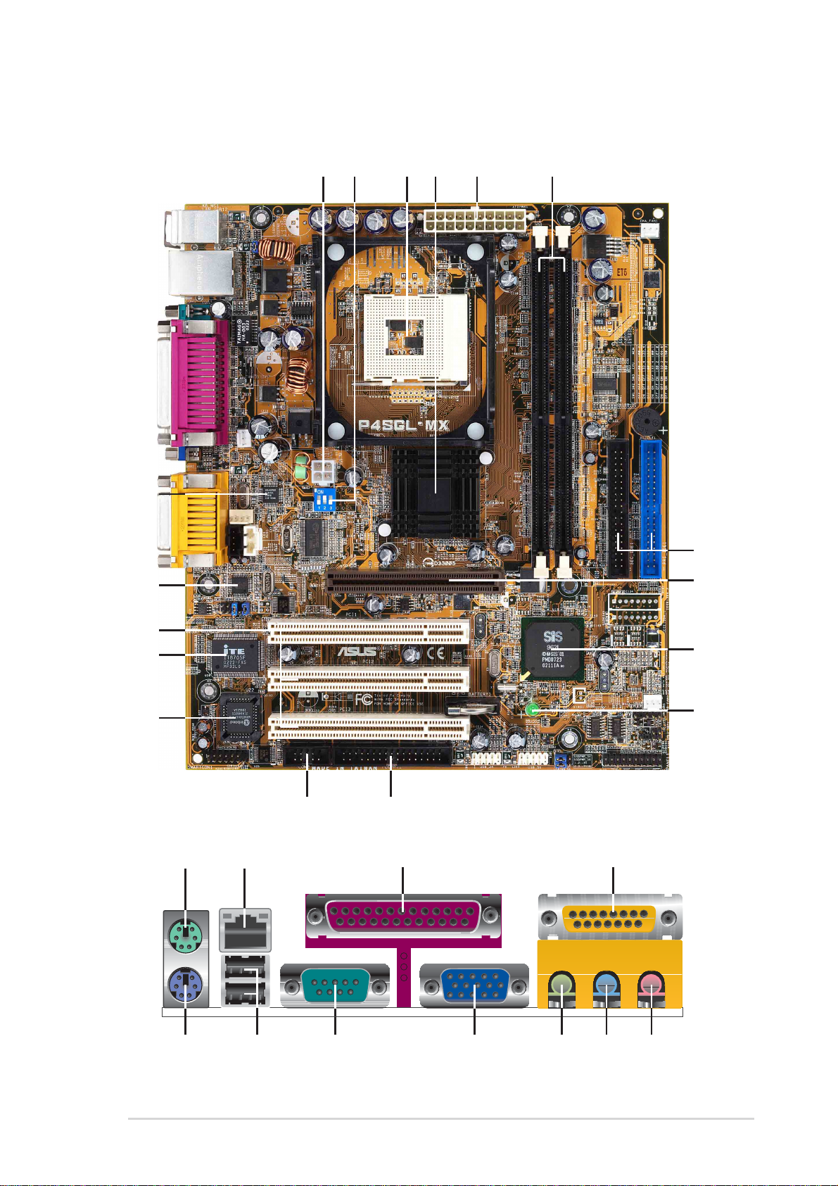
1.3 Motherboard components
17
16
15
14
13
12
11
7
8
9
1
2628 2527 222324
ASUS P4SGL-MX Motherboard
1-3

1
ATX 12V connector. This power connector connects the 4-pin 12V plug
from the ATX 12V power supply.
2
DIP Switches. This 3-switch Dual Inline Package (DIP) allows you to set
the CPU external frequency.
3
CPU Sockets. A 478-pin surface mount, Zero Insertion Force (ZIF) socket
®
for the Intel
Pentium® 4 P478 Willamette & Northwood Processor with 100
MHz system bus that allows 1.4 GHz ~ 2.6 GHz plus of core frequency.
4
NorthBridge Controller. This SIS SIS650GL controller integrates a high
®
performance host interface for the Intel
Pentium® 4 processor, a memory
controller and an integrated graphics interface.
5
ATX power connector. This standard 20-pin connector connects to an
ATX 12V power supply. The power supply must have at least 1A on the
+5V standby lead (+5VSB).
6
DDR DIMM Sockets. These two 184-pin DIMM sockets support up to 2GB
using non-ECC PC2100/1600 DDR SDRAM DIMMs with 2.1GBytes/sec of
transfer rate.
7
IDE Connectors. These dual-channel bus master IDE connectors support
up to four Ultra DMA133/100/66, PIO Modes 3 & 4 IDE devices. Both the
primary(blue) and secondary(black) connectors are slotted to prevent
incorrect insertion of the IDE ribbon cable.
8
9
10
11
12
13
AGP Slot. This Accelerated Graphics Port (AGP) slot only supports 1.5V
AGP4X mode graphics cards for 3D graphical applications.
South bridge controller. This SIS SIS962L0 MuTIOL Media I/O controller
integrates the AC’97 Interface, four Universal Serial Bus Host controllers,
two IDE Master/Slave controllers, Flash BIOS, and PCI bus for three PCI
Slots.
Onboard LED. This onboard LED lights up if there is a standby power on
the motherboard. This LED acts as a reminder to turn off the system power
before plugging or unplugging devices.
Floppy Disk connector. This connector connects the provided ribbon
cable for the floppy disk drive. One side of the connector is slotted to
prevent incorrect insertion of the floppy disk cable.
COM2 connector. This 9-pin connector connects to a COM2 port.
Flash ROM. This 2MB firmware contains the programmable BIOS
program.
1-4
Chapter 1: Motherboard Information

14
Super I/O chipset. This interface provides the commonly used Super I/O
functionality. The chipset supports a high-performance floppy disk
controller for a 360K/720K/1.44M/2.88M floppy disk drive, a PS/2 keyboard
and mouse port, a multi-mode parallel port, a game port and serial ports.
15
16
17
18
19
20
21
22
23
PCI slots. These 32-bit PCI 2.2 expansion slots support bus master PCI
cards like SCSI and LAN cards with 133MB/s maximum output.
Audio/Modem CODEC. This audio CODEC is AC ’97 compliant.
Single-Chip Fast Ethernet controller. The RealTek 8201BL Single LAN
PHY Fast Ethernet controller allows connection to a Local Area Network
(LAN) through a network hub. (Onboard LAN model only)
PS/2 mouse port. This green 6-pin connector is for a PS/2 mouse.
RJ-45 port. This port allows connection to a Local Area Network (LAN)
through a network hub. (Onboard LAN model only)
Parallel port. This 25-pin port connects a parallel printer, a scanner, or
other devices.
GAME/MIDI port. This port supports a joystick or a game pad for playing
games, and MIDI devices for playing or editing audio files.
Microphone jack. This Mic (pink) jack connects a microphone.
Line In jack. This Line In (light blue) jack connects a tape player or other
audio sources.
24
25
26
27
28
Line Out jack. This Line Out (lime) jack connects a headphone or a
speaker.
Video port. This port connects a VGA monitor.
Serial port. This port connects to your serial mouse and other serial
devices.
USB 2.0 ports. These two 4-pin Universal Serial Bus 2.0 (USB 2.0) ports
are available for connecting USB devices such as a mouse and PDA.
PS/2 keyboard port. This purple 6-pin connector is for a PS/2 keyboard.
ASUS P4SGL-MX Motherboard
1-5
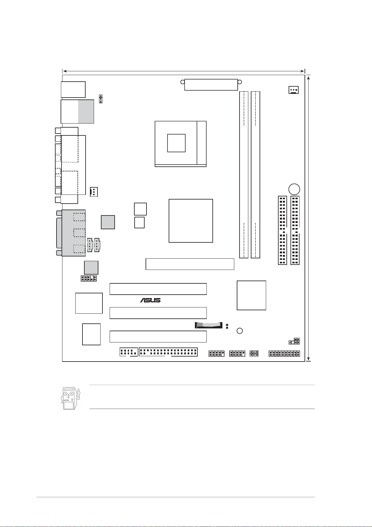
1.4 Motherboard layout
®
20.9cm (8.2in)
PS/2
T: Mouse
B: Keyboard
Bottom:
Top:
USB1
RJ-45
USB2
COM1
PARALLEL PORT
VGA
Line
Out
Line
In
Mic
In
GAME_AUDIO
CD1
Audio
Codec
USBPWR_12
CPU_FAN1
RTL8201BL
AUX1
ATX12V1
P4SGL-MX
SW1
Memory
Controller
Accelerated Graphics Port
ATX Power Connector
Socket 478
SiS650
HOST/
(AGP)
CHA_FAN1
BUZZER1
DDR DIMM2 (64/72 bit, 184-pin module)
DDR DIMM1 (64/72 bit, 184-pin module)
24.4cm (9.6in)
2 3
0 1
FP_AUDIO1
PCI Slot 1
Super
I/O
SiS962L
SiS962L
MuTLOL
Media
I/0
PCI Slot 2
USB_34
CLRTC1
SB_PWR1
USB_56
USBPWR_34
USBPWR_56
2Mbit
Flash
BIOS
COM2
BATTERY1
PCI Slot 3
FLOPPY1
The LAN and audio features are optional. These components are
grayed out in the above motherboard layout.
SEC_IDE1
IDE_LED1
SPDIF_OUT1
PANEL1
PRI_IDE1
1-6
Chapter 1: Motherboard Information
1.5 Before you proceed
®
Take note of the following precautions before you install motherboard components
or change any motherboard settings.
1. Unplug the power cord from the wall socket before touching any
component.
2. Use a grounded wrist strap or touch a safely grounded object or to
a metal object, such as the power supply case, before handling
components to avoid damaging them due to static electricity.
3. Hold components by the edges to avoid touching the ICs on them.
4. Whenever you uninstall any component, place it on a grounded
antistatic pad or in the bag that came with the component.
5. Before you install or remove any component, ensure that the
ATX power supply is switched off or the power cord is
detached from the power supply. Failure to do so may cause
severe damage to the motherboard, peripherals, and/or
components.
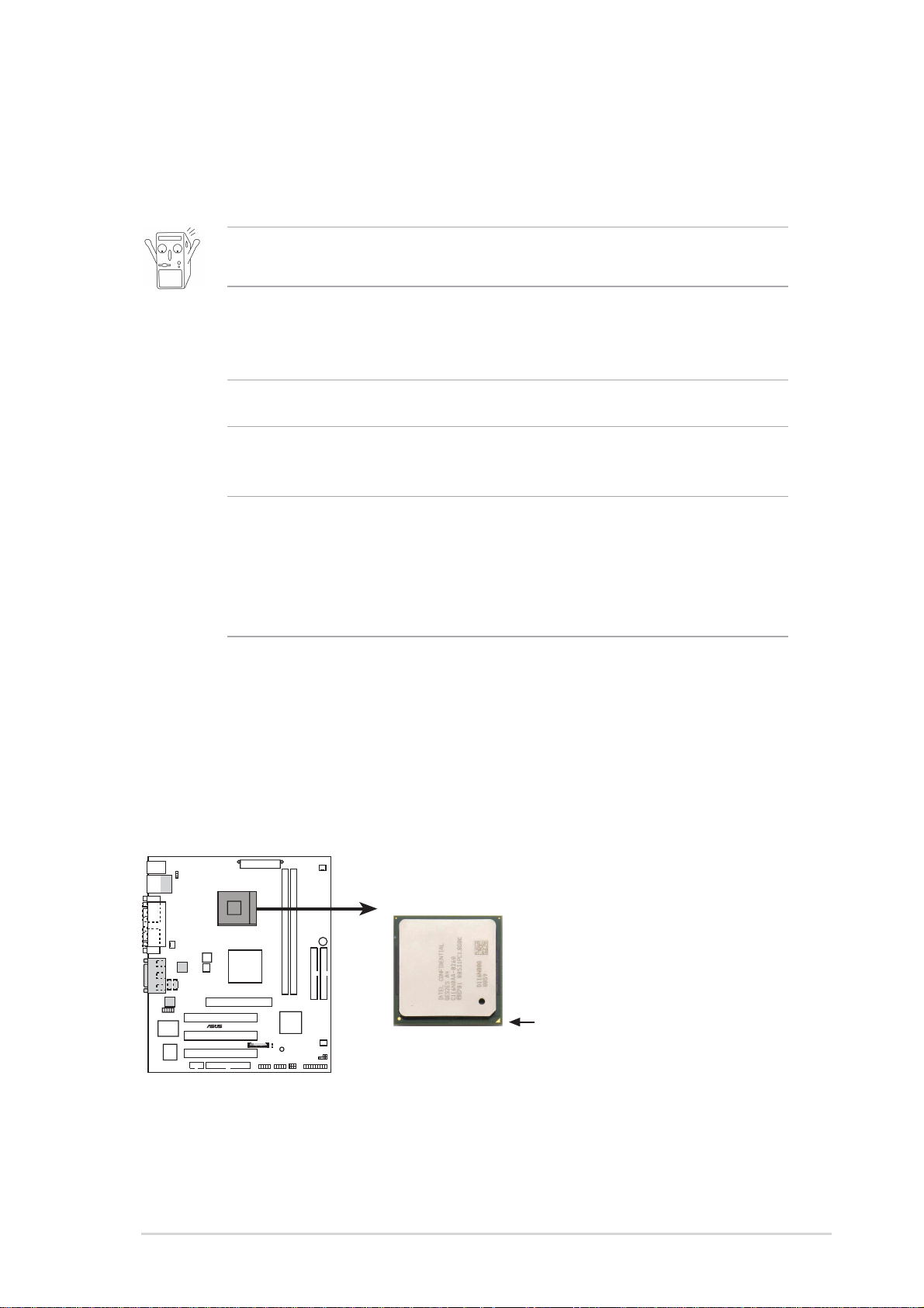
1.6 Central Processing Unit (CPU)
The motherboard comes with a surface mount 478-pin Zero Insertion Force (ZIF)
socket. This socket is specifically designed for the Intel
Northwood Processor.
P4SGL-MX
P4SGL-MX Socket 478
®
Pentium® 4 478/
Gold Arrow
ASUS P4SGL-MX Motherboard
1-7
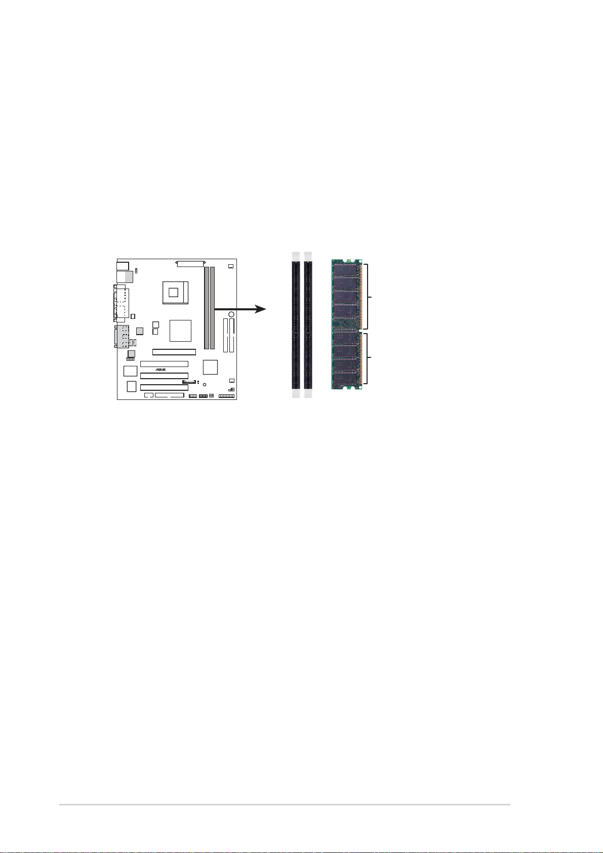
1.7 System memory
®
s
The motherboard has two Double Data Rate (DDR) DIMM sockets that supports
up to 2GB non-ECC PC2100/1600 DDR.
A DDR DIMM has the same physical dimensions as an SDR DIMM, but it has a
184-pin footprint compared to the 168-pin of the SDR DIMM. Also, a DDR DIMM is
single notched while an SDR DIMM is double notched.
104 Pin
P4SGL-MX
80 Pins
P4SGL-MX 184-Pin DDR DIMM Sockets
1.8 Expansion slots
The P4SGL-MX motherboard has three (3) expansion slots. The following subsections describe the slots and the expansion cards that they support.
1.8.1 Configuring an expansion card
After physically installing the expansion card, configure the card by adjusting the
software settings.
1. Turn on the system and change the necessary BIOS settings, if any.
2. Assign an IRQ to the card. Refer to the tables below.
3. Install the software drivers for the expansion card.
1-8
Chapter 1: Motherboard Information
1.8.2 Standard Interrupt Assignments
®
IRQ Standard Function
0 System Timer
1 Keyboard Controller
2 Programmable Interrupt Controller
3* USB Universal Host Controller
4* Communications Port (COM1)
5* Onboard Audio
6 Standard Floppy Disk Controller
7* Printer Port (LPT1)
8 System CMOS/Real Time Clock
9* Onboard LAN
10* USB Universal Host Controller
11* Onboard VGA
12* PS/2 Compatible Mouse Port
13 Numeric Data Processor
14* Ultra A T A Controller
15* Secondary Ultra ATA Controller
*These IRQs are usually available for ISA or PCI devices.
IRQ assignments for this motherboard
ABCD
PCI slot 1 — shared — —
PCI slot 2 — — shared —
PCI slot 3 — — — shared
AGP slot shared — — —
Onboard USB controller HC0 — — — shared
Onboard USB controller HC1 — — — shared
Onboard LAN — — shared —
Onboard Audio — — shared —
Onboard VGA shared — — —
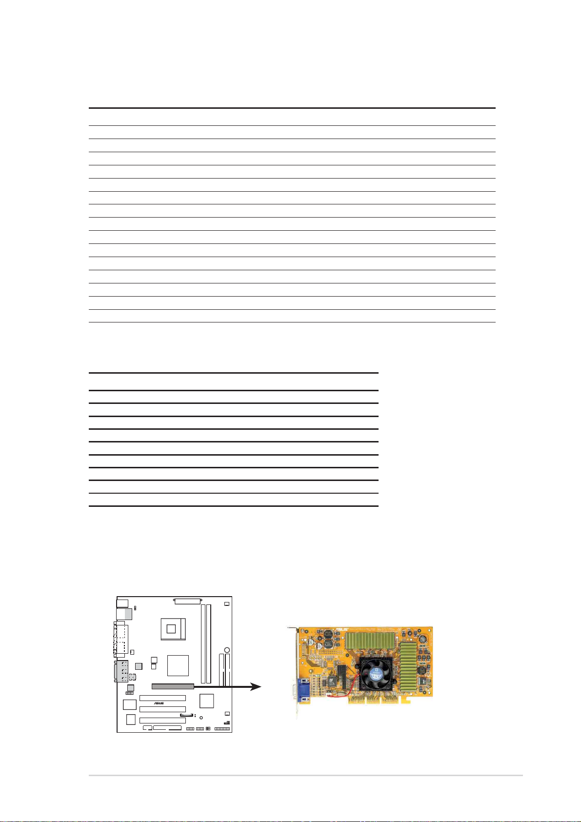
1.8.3 AGP slot
This motherboard has an Accelerated Graphics Port (AGP) slot that support +1.5V
and +3.3V AGP 4X cards. Note the notches on the card golden fingers to ensure
that they fit the AGP slot on your motherboard.
P4SGL-MX
P4SGL-MX Accelerated Graphics Port (AGP )
ASUS P4SGL-MX Motherboard
1-9
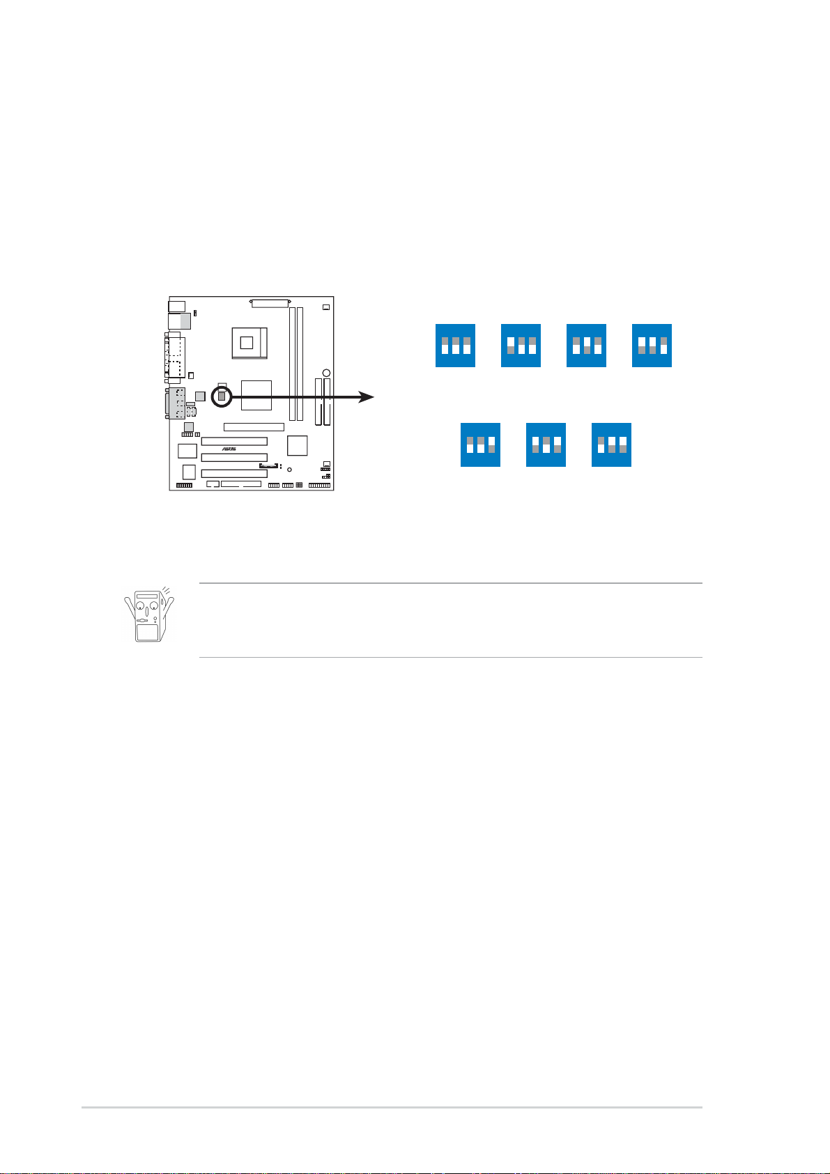
1.9 Switches and Jumpers
®
SW1
z
z
1. CPU Frequency Selection (SW Switches 1-3)
This option tells the clock generator what frequency to send the CPU. This
allows the selection of the CPU’s external frequency (or Bus Clock). The Bus
Clock multiplied by the Frequency Multiple equals the CPU’s internal
frequency (the advertised CPU speed).
P4SGL-MX
ON
12
CPU
100.2MHz
MEM
100.2MHz 133.4MHz 133.6MHz 100.1MH
CPU
100.2MHz
167.0MHz 166.6MHz 150.3MHz
MEM
3
ON
12
ON
12
133.4MHz
ON
3
133.3MHz
3
12
ON
12
100.2MHz
ON
3
100.2MHz
3
12
ON
12
133.4MH
3
P4SGL-MX CPU
External Frequency Selection
Set the CPU frequency only to the recommended settings.
Frequencies other than the recommended CPU bus frequencies are
not guaranteed to be stable.
3
1-10
Chapter 1: Motherboard Information
 Loading...