


ASUS P4R800-V User Manual

P4R800-V
Deluxe
User Guide
Motherboard

Checklist
E1391
First Edition V1
December 2003
Copyright © 2003 ASUSTeK COMPUTER INC. All Rights Reserved.
No part of this manual, including the products and software described in it, may be
reproduced, transmitted, transcribed, stored in a retrieval system, or translated into any
language in any form or by any means, except documentation kept by the purchaser for
backup purposes, without the express written permission of ASUSTeK COMPUTER INC.
(“ASUS”).
Product warranty or service will not be extended if: (1) the product is repaired, modified or
altered, unless such repair, modification of alteration is authorized in writing by ASUS; or (2)
the serial number of the product is defaced or missing.
ASUS PROVIDES THIS MANUAL “AS IS” WITHOUT WARRANTY OF ANY KIND, EITHER
EXPRESS OR IMPLIED, INCLUDING BUT NOT LIMITED TO THE IMPLIED WARRANTIES
OR CONDITIONS OF MERCHANTABILITY OR FITNESS FOR A PARTICULAR PURPOSE.
IN NO EVENT SHALL ASUS, ITS DIRECTORS, OFFICERS, EMPLOYEES OR AGENTS BE
LIABLE FOR ANY INDIRECT, SPECIAL, INCIDENTAL, OR CONSEQUENTIAL DAMAGES
(INCLUDING DAMAGES FOR LOSS OF PROFITS, LOSS OF BUSINESS, LOSS OF USE
OR DATA, INTERRUPTION OF BUSINESS AND THE LIKE), EVEN IF ASUS HAS BEEN
ADVISED OF THE POSSIBILITY OF SUCH DAMAGES ARISING FROM ANY DEFECT OR
ERROR IN THIS MANUAL OR PRODUCT.
SPECIFICATIONS AND INFORMATION CONTAINED IN THIS MANUAL ARE FURNISHED
FOR INFORMATIONAL USE ONLY, AND ARE SUBJECT TO CHANGE AT ANY TIME
WITHOUT NOTICE, AND SHOULD NOT BE CONSTRUED AS A COMMITMENT BY ASUS.
ASUS ASSUMES NO RESPONSIBILITY OR LIABILITY FOR ANY ERRORS OR
INACCURACIES THAT MAY APPEAR IN THIS MANUAL, INCLUDING THE PRODUCTS
AND SOFTWARE DESCRIBED IN IT.
Products and corporate names appearing in this manual may or may not be registered
trademarks or copyrights of their respective companies, and are used only for identification or
explanation and to the owners’ benefit, without intent to infringe.
ii

Contents
Notices ...........................................................................................vi
Safety information ......................................................................... vii
About this guide............................................................................ viii
P4R800-V Deluxe specification summary .......................................x
Chapter 1: Product introduction
1.1 Welcome! .............................................................................. 1
1.2 Package contents.................................................................. 1
1.3 Special features..................................................................... 2
1.3.1 Product highlights ..................................................... 2
1.3.2 ASUS unique features .............................................. 4
Chapter 2: Hardware information
2.1 Before you proceed ............................................................ 2-1
2.2 Motherboard layout ............................................................ 2-2
2.2.1 Major components ................................................. 2-3
2.2.2 Placement direction ............................................... 2-4
2.2.3 Screw holes ........................................................... 2-4
2.3 Central Processing Unit (CPU)........................................... 2-5
2.3.1 Overview ................................................................ 2-5
2.3.2 Installing the CPU .................................................. 2-6
2.3.3 Installing the heatsink and fan ............................... 2-7
2.3.4 Connecting the CPU fan cable .............................. 2-9
Features
2.4 System memory ............................................................... 2-10
2.4.1 Overview .............................................................. 2-10
2.4.2 Memory configurations ........................................ 2-10
2.4.3 Installing a DIMM ................................................. 2-13
2.4.4 Removing a DIMM ............................................... 2-13
2.5 Expansion slots ................................................................ 2-14
2.5.1 Installing an expansion card ................................ 2-14
2.5.2 Configuring an expansion card ............................ 2-14
2.5.3 Interrupt assignments .......................................... 2-15
2.5.4 PCI slots .............................................................. 2-16
2.5.5 AGP slot............................................................... 2-16
2.5.6 Wi-Fi slot .............................................................. 2-17
iii

Safeguards
Contents
2.6 Jumpers............................................................................ 2-18
2.7 Connectors ....................................................................... 2-20
2.7.1 Rear panel connectors......................................... 2-20
2.7.2 Internal connectors .............................................. 2-21
Chapter 3: Powering up
3.1 Starting up for the first time ................................................ 3-1
3.2 BIOS beep codes ............................................................... 3-1
3.3 ASUS POST Reporter™ .................................................... 3-2
3.3.1 Vocal POST messages .......................................... 3-2
3.3.2 Winbond Voice Editor ............................................ 3-4
3.4 Powering off the computer ................................................. 3-7
Chapter 4: BIOS setup
4.1 Managing and updating your BIOS .................................... 4-1
4.1.1 Creating a bootable floppy disk ............................. 4-1
4.1.2 Updating BIOS using the AwardBIOS Flash Utility .. 4-2
4.1.3 Recovering the BIOS with CrashFree BIOS 2 ....... 4-4
4.1.4 ASUS Update ........................................................ 4-6
4.2 BIOS Setup program .......................................................... 4-8
4.2.1 BIOS menu screen ................................................ 4-9
4.2.2 Menu bar................................................................ 4-9
4.2.3 Legend bar........................................................... 4-10
4.2.4 General help ........................................................ 4-10
4.2.5 Sub-menu ............................................................ 4-10
4.2.6 Pop-up window .................................................... 4-10
4.3 Main menu.........................................................................4-11
4.4 Advanced menu ............................................................... 4-16
4.4.1 Frequency/Voltage Control .................................. 4-17
4.4.2 Chip Configuration ............................................... 4-18
4.4.3 I/O Device Configuration...................................... 4-21
4.4.4 PCI Configuration ................................................ 4-23
4.4.5 Instant Music........................................................ 4-25
4.5 Power menu ..................................................................... 4-26
4.5.1 Power Up Control ................................................ 4-27
4.5.2 Hardware Monitor ................................................ 4-28
iv
4.6 Boot menu ........................................................................ 4-29
4.7 Exit menu ......................................................................... 4-31

Contents
Chapter 5: Software support
5.1 Install an operating system................................................. 5-1
5.2 Support CD information...................................................... 5-1
5.2.1 Running the support CD ........................................ 5-1
5.2.2 Drivers menu ......................................................... 5-2
5.2.3 Utilities menu ......................................................... 5-3
5.2.4 ASUS contact information...................................... 5-4
5.2.5 Other information ................................................... 5-5
5.3 ATI IGP Catalyst™ ............................................................. 5-7
5.3.1 Left-click menu....................................................... 5-7
5.3.2 Right-click menu .................................................... 5-8
5.3.3 Managing multiple displays.................................... 5-8
5.4 Software information ........................................................ 5-10
5.4.1 Multi-channel audio feature ................................. 5-10
5.4.2 ASUS MyLogo2™................................................ 5-13
5.4.3 ASUS Instant Music ............................................. 5-15
5.5 SiS RAID configurations................................................... 5-17
5.5.1 Installing the hard disks ....................................... 5-18
5.5.2 SiS RAID Setting Utility........................................ 5-19
5.5.3 SiSRAID Utility ..................................................... 5-22
®
5.6 Marvell
5.7 Makedisk.exe ................................................................... 5-26
Virtual Cable Tester™ (VCT) Technology........... 5-25
Quick Reference Card
v

Notices
Federal Communications Commission Statement
This device complies with FCC Rules Part 15. Operation is subject to the
following two conditions:
• This device may not cause harmful interference, and
• This device must accept any interference received including interference
that may cause undesired operation.
This equipment has been tested and found to comply with the limits for a
Class B digital device, pursuant to Part 15 of the FCC Rules. These limits
are designed to provide reasonable protection against harmful interference
in a residential installation. This equipment generates, uses and can radiate
radio frequency energy and, if not installed and used in accordance with
manufacturer’s instructions, may cause harmful interference to radio
communications. However, there is no guarantee that interference will not
occur in a particular installation. If this equipment does cause harmful
interference to radio or television reception, which can be determined by
turning the equipment off and on, the user is encouraged to try to correct the
interference by one or more of the following measures:
• Reorient or relocate the receiving antenna.
• Increase the separation between the equipment and receiver.
• Connect the equipment to an outlet on a circuit different from that to
which the receiver is connected.
• Consult the dealer or an experienced radio/TV technician for help.
The use of shielded cables for connection of the monitor to the
graphics card is required to assure compliance with FCC regulations.
Changes or modifications to this unit not expressly approved by the
party responsible for compliance could void the user’s authority to
operate this equipment.
Canadian Department of Communications Statement
This digital apparatus does not exceed the Class B limits for radio noise
emissions from digital apparatus set out in the Radio Interference
Regulations of the Canadian Department of Communications.
This class B digital apparatus complies with Canadian ICES-003.
vi

Safety information
Electrical safety
• To prevent electrical shock hazard, disconnect the power cable from
the electrical outlet before relocating the system.
• When adding or removing devices to or from the system, ensure that
the power cables for the devices are unplugged before the signal
cables are connected. If possible, disconnect all power cables from the
existing system before you add a device.
• Before connecting or removing signal cables from the motherboard,
ensure that all power cables are unplugged.
• Seek professional assistance before using an adpater or extension
cord. These devices could interrupt the grounding circuit.
• Make sure that your power supply is set to the correct voltage in your
area. If you are not sure about the voltage of the electrical outlet you
are using, contact your local power company.
• If the power supply is broken, do not try to fix it by yourself. Contact a
qualified service technician or your retailer.
Operation safety
• Before installing the motherboard and adding devices on it, carefully
read all the manuals that came with the package.
• Before using the product, make sure all cables are correctly connected
and the power cables are not damaged. If you detect any damage,
contact your dealer immediately.
• To avoid short circuits, keep paper clips, screws, and staples away
from connectors, slots, sockets and circuitry.
• Avoid dust, humidity, and temperature extremes. Do not place the
product in any area where it may become wet.
• Place the product on a stable surface.
• If you encounter technical problems with the product, contact a
qualified service technician or your retailer.
vii

About this guide
This user guide contains the information you need when installing and
configuring the motherboard.
How this guide is organized
This guide contains the following parts:
• Chapter 1: Product introduction
This chapter describes the features of the motherboard. It includes
brief descriptions of the special attributes of the motherboard and the
new technology it supports.
• Chapter 2: Hardware information
This chapter lists the hardware setup procedures that you have to
perform when installing system components. It includes description of
the switches, jumpers, and connectors on the motherboard.
• Chapter 3: Powering up
This chapter describes the power up sequence and gives information
on the BIOS beep codes and the ASUS Post Reporter™ feature.
• Chapter 4: BIOS setup
This chapter tells how to change system settings through the BIOS
Setup menus. Detailed descriptions of the BIOS parameters are also
provided.
• Chapter 5: Software support
This chapter describes the contents of the support CD that comes with
the motherboard package.
• Quick Reference Card
viii

Conventions used in this guide
To make sure that you perform certain tasks properly, take note of the
following symbols used throughout this guide.
WARNING: Information to prevent injury to yourself when trying
to complete a task.
CAUTION: Information to prevent damage to the components
when trying to complete a task.
IMPORTANT: Information that you MUST follow to complete a
task.
NOTE: Tips and additional information to aid in completing a task.
Where to find more information
Refer to the following sources for additional information and for product
and software updates.
1. ASUS websites
The ASUS websites worldwide provide updated information on ASUS
hardware and software products. Refer to the ASUS contact
information.
2. Optional documentation
Your product package may include optional documentation, such as
warranty flyers, that may have been added by your dealer. These
documents are not part of the standard package.
ix

P4R800-V Deluxe specification summary*
CPU
Chipset
Front Side Bus
Memory
Expansion slots
Storage
Socket 478 for Intel
with speeds of up to 3.2+ GHz
On-die 512KB/256KB L2 cache with full speed
Supports Intel® Hyper-Threading Technology
New power design supports next generation Intel Prescott CPU
ATI RADEON™ 9100 IGP
ATI IXP 150
800/533/400 MHz
Dual-channel memory architecture
4 x 184-pin DDR DIMM sockets for up to 4GB system
Supports PC3200*/2700/2100 unbuffered ECC or non-ECC
DDR DIMMs
up to 2GB system memory.)
1 x AGP 8X/4X
5 x PCI
1 x Wi-Fi
South bridge (IXP150) supports
- 2 x UltraDMA100/66
SiS 180 RAID controller supports
- 1 x UltraDMA133/100/66
- 2 x Serial ATA with RAID0, RAID1, RAID0+1
®
Pentium® 4/Celeron processor
(*Maximum of one PC3200 DIMM per channel for
Integrated Graphics
IEEE 1394
LAN
Audio
ASUS unique features
ATI Radeon™ 9100 IGP 3D graphics engine supports
- Maximum 128MB of display memory
- Microsoft
- TV encoder and DVO
VIA 6307 IEEE 1394 controller
- supports 2 x IEEE 1394 connectors
Marvell
10/100/1000 BASE-T Ethernet
ADI AD1888 SoundMAX 6-channel audio CODEC
POST Reporter™
Instant Music
C.P.R. (CPU Parameter Recall)
CrashFree BIOS 2
Multi-language BIOS
Q-Fan
MyLogo2
(Continued on the next page)
®
DirectX 8.1 and OpenGL structure
®
88E001 Gigabit LAN controller supports
x
P4R800-V Deluxe specification summary*
Rear panel I/O
Internal I/O
1 x Parallel port
1 x VGA port
1 x S-Video port
1 x Composite video port
1 x PS/2 keyboard port
1 x PS/2 mouse port
1 x IEEE 1394 port
4 x USB 2.0 ports
1 x RJ-45 port
Line In/Line Out/Microphone ports
2 x Serial connectors
1 x USB 2.0 connector for 2 additional USB ports
1 x IEEE 1394 connector for 1 additional 1394 port
CPU/power/chassis fan connectors
20-pin/4-pin ATX power connectors
GAME/MIDI connector
S/PDIF Out connector
CD/AUX/Modem audio connectors
Front panel audio connector
Panel connector
Chassis intrusion connector
BIOS features
Industry standard
Manageability
Supported OS
Power requirement
Form Factor
Support CD contents
*Specifications are subject to change without notice.
4MB Flash ROM, Phoenix Award BIOS, PnP, DMI2.0,
WfM2.0, SM BIOS 2.3, ACPI, ASUS MyLogo2, AWDFlash
PCI 2.2, USB 2.0
DMI 2.0, chassis intrusion
Windows® ME/2000/XP
ATX power supply (with 4-pin 12V plug)
ATX form factor: 12 in x 9.6 in (30.5 cm x 24.5 cm)
Device drivers
ASUS PC Probe
ASUS Update
Microsoft
Winbond Voice Editor
Trend Micro™ PC-cillin 2002
Adobe® Acrobat Reader® V5.0
ASUS Screensaver
®
DirectX 8.1
xi

xii

Chapter 1
This chapter describes the features of the
motherboard. It includes brief descriptions
of the special attributes of the motherboard
and the new technology it supports.
Product introduction

Chapter summary
1.1 Welcome! ........................................................ 1-1
1.2 Package contents .......................................... 1-1
1.3 Special features ............................................. 1-2
ASUS P4R800-V Deluxe motherboard

1.1 Welcome!
Thank you for buying the ASUS P4R800-V Deluxe motherboard!
The ASUS
and latest technologies making it another standout in the long line of
ASUS quality motherboards!
Before you start installing the motherboard, and hardware devices on it,
check the items in your package with the list below.
P4R800-V Deluxe motherboard delivers a host of new features
1.2 Package contents
Check your P4R800-V Deluxe package for the following items.
ASUS P4R800-V Deluxe motherboard
ASUS P4R800-V series support CD
2 x SATA cable
2 x SATA power cable
1 x 80-conductor ribbon cables for UltraDMA IDE drives
9-pin COM cable
Ribbon cable for a 3.5-inch floppy drive
S/PDIF out module
USB/GAME module
I/O shield
Bag of extra jumper caps
Instant Music keyboard label
InterVideo WinDVD Suite
User Guide
Quick Reference Card (last page of the User Guide)
Quick Setup Guide (Retail boxes only.)
Jumpers and connectors stickers (Retail boxes only.)
If any of the above items is damaged or missing, contact your retailer.
ASUS P4R800-V Deluxe motherboard user guide
1-1

1.3 Special features
1.3.1 Product highlights
800MHz FSB CPU support
The P4R800-V Deluxe comes with a 478-pin surface mount, Zero Insertion
Force (ZIF) socket for the Intel® Pentium® 4 Northwood/Willamette
processor in the 478-pin package with 512/256KB L2 cache on 0.13
micron process. This motherboard supports 800/533/400 MHz system
front side bus that allows 6.4GB/s, 4.3GB/s and 3.2GB/s data transfer
rates, respectively. The P4R800-V Deluxe also supports the Intel
Hyper-Threading Technology and the next-generation Intel® Prescott CPU.
See page 2-5.
ATi RADEON™ 9100 IGP/IXP 150 chipset
The embedded RADEON™ 9100 Integrated Graphics Processor (IGP)
northbridge and the IXP 150 southbridge chipset control all interfaces to
ensure an efficient and reliable computing performance.
®
The RADEON™ 9100 IGP provides processor interface with 800/533/400
MHz frequency, system memory interface at 400/333/266MHz operation,
and 1.5V AGP interface that supports AGP 8X specification.
The IXP 150 is a subsystem that integrates various I/O functions including
dual-channel ATA100 bus master IDE controller, up to six USB 2.0/1.1
ports, I/O APIC interrupt, and LPC, AC’97 and PCI 2.2 interfaces. ATI’s
proprietary A-Link interface connects the IXP 150 with the RADEON™ IGP
at speeds of up to 266MB/s.
Dual channel DDR400 memory support
The P4R800-V Deluxe supports a single or a dual memory architecture for
up to 4GB system memory. Four (4) 184-pin DIMM sockets are available
for installation of unbuffered non-ECC DDR400/300/266 DIMMs.
See page 2-11.
1-2
Chapter 1: Product introduction

ATI RADEON™ 9100 IGP 2D/3D engine
Integrated in the IGP chipset is the ATI RADEON™ 2D/3D graphics engine
with maximum 128MB shared display memory. The integrated graphics
also supports TV out function via the S-Video and composite ports in the
motherboard rear panel. The RADEON™ 3D graphics engine achieves a
maximum resolution of 2048x1536 at 32bpp and implements innovative
ATI technologies including Pixel Tapestry™ II, Smartshader™,
Smoothvision™, and Video Immersion™ II. See page 5-7.
Ai NET solution
Ai NET supports the onboard Marvell® 88E001 Gigabit LAN controller for a
Fast 10/100/1000 BASE-T Ethernet. The Gigabit LAN controller comes
with the Virtual Cable Tester (VCT) that intelligently diagnoses and reports
cable faults from a remote location up to 100 meters to help users monitor
and improve network quality. See page 5-25.
SoundMAX digital audio system
The SoundMax Digital Audio System is the industry’s highest performance
and most reliable audio solution for business professionals, audiophiles,
musicians, and gamers. SoundMAX Digital Audio System can output 5.1
channel surround and features state-of-the-art DLS2 MIDI synthesizer with
Yamaha DLSbyXG sound set, 5.1 Virtual Theater™ and supports all major
game audio technologies including Microsoft DirectX™8.0, Microsoft
DirectSound 3D™, A3D, MacroFX, ZoomFX, MultiDrive 5.1 and EAX. See
page 5-10.
This motherboard also comes with a S/PDIF module to turn your computer
into a high-end entertainment system with digital connectivity to powerful
sound systems. See page 2-25.
Serial ATA solution
The embedded SiS 180 controller supports two Serial ATA (SATA)
interface, a revolutionary replacement of the Parallel ATA storage
interface. The Serial ATA specification allows for thinner, more flexible
cables with lower pin count, reduced voltage requirement, up to 150 MB/s
data transfer rate. See page 2-23.
ASUS P4R800-V Deluxe motherboard user guide
1-3

RAID 0, 1, 0+1 support
The SiS 180 RAID controller supports two Serial ATA150 and UltraDMA133
drives for RAID 0,1, 0+1 configuration. This provides a high-performance
RAID solution for hard disk performance and data back-up protection without
the cost of additional RAID cards. See page 2-23 and 5-17.
USB 2.0 technology
The motherboard implements the Universal Serial Bus (USB) 2.0
specification, dramatically increasing the connection speed from the 12
Mbps bandwidth on USB 1.1 to a fast 480 Mbps on USB 2.0. USB 2.0 is
backward compatible with USB 1.1. See page 2-27.
IEEE 1394 support
The onboard VIA6307 controller supports two IEEE 1394 ports that
provides high-speed and flexible PC connectivity to a wide range of
peripherals and devices compliant to IEEE 1394 standards. The IEEE
1394 allows up to 400Mbps transfer rates through simple, low-cost,
high-bandwidth asynchronous (real-time) data interfacing between
computers, peripherals, and consumer electronic devices such as
camcorders, VCRs, printers,TVs, and digital cameras. See page 2-25.
1.3.2 ASUS unique features
Ai BIOS
The Ai Bios is a combination of three ASUS intelligent solutions:
CrachFree BIOS2, Q-Fan and Post Reporter.
CrashFree BIOS2
This feature allows you to restore the original BIOS data from the support
CD, or from a bootable floppy disk, when the BIOS codes and data are
corrupted. This protection eliminates the need to buy a replacement ROM
chip. See page 4-4.
Q-Fan technology
The ASUS Q-Fan technology smartly adjusts the fan speeds according to
the system loading to ensure quiet, cool, and efficient operation.
See page 4-28.
1-4
Chapter 1: Product introduction
POST Reporter™
The motherboard offers a new exciting feature called the ASUS POST
Reporter™ to provide friendly voice messages and alerts during the
Power-On Self-Tests (POST) informing you of the system boot status and
causes of boot errors, if any. The bundled Winbond Voice Editor software
lets you to customize the voice messages in different languages.
See page 3-2.
Wi-Fi slot
The ASUS Wi-Fi slot is based on the IEEE 802.11b/g wireless standard
and is specifically designed for the ASUS WiFi-b™ add-on card for settingup a wireless LAN environment. The ASUS WiFi-b™ add-on card comes
with an exclusive Software Access Point (AP) feature to save the extra
cost of a stand-alone AP. This proprietary slot also supports the IEEE
802.11g wireless LAN standard for future upgrades. See page 2-17.
Multi-language BIOS
The multi-language BIOS allows you to select the language of your choice
from the available options. The localized BIOS menus allow you to
configure easier and faster. Supported languages include English,
German, and Japanese. See page 4-11.
C.P.R. (CPU Parameter Recall)
The C.P.R. feature of the motherboard BIOS allows automatic re-setting to
the BIOS default settings in case the system hangs due to overclocking.
When the system hangs due to overclocking, C.P.R. eliminates the need to
open the system chassis and clear the RTC data. Simply shut down and
reboot the system, and BIOS automatically restores the CPU default
setting for each parameter.
MyLogo2
This new feature present in the motherboard allows you to personalize and
add style to your system with customizable boot logos. The ASUS
MyLogo2 is automatically installed when you install the ASUS Update
utility from Utilities menu in the support CD. See page 5-13.
ASUS P4R800-V Deluxe motherboard user guide
1-5

Instant Music
This unique feature allows you to playback audio files even before
entering the operating system. Just press the ASUS Instant Music special
function keys and enjoy the music! See page 5-15.
1-6
Chapter 1: Product introduction

Chapter 2
This chapter lists the hardware setup
procedures that you have to perform when
installing system components. It includes
description of the switches, jumpers, and
connectors on the motherboard.
Hardware information

Chapter summary
2.1 Before you proceed ....................................... 2-1
2.2 Motherboard layout ....................................... 2-2
2.3 Central Processing Unit (CPU) ..................... 2-5
2.4 System memory ........................................... 2-10
2.5 Expansion slots ........................................... 2-14
2.6 Jumpers ........................................................ 2-18
2.7 Connectors ................................................... 2-20
ASUS P4R800-V Deluxe motherboard
2.1 Before you proceed
®
d
Take note of the following precautions before you install motherboard
components or change any motherboard settings.
• Unplug the power cord from the wall socket before touching any
component.
• Use a grounded wrist strap or touch a safely grounded object or to
a metal object, such as the power supply case, before handling
components to avoid damaging them due to static electricity.
• Hold components by the edges to avoid touching the ICs on them.
• Whenever you uninstall any component, place it on a grounded
antistatic pad or in the bag that came with the component.
• Before you install or remove any component, ensure that the
ATX power supply is switched off or the power cord is
detached from the power supply. Failure to do so may cause
severe damage to the motherboard, peripherals, and/or
components.
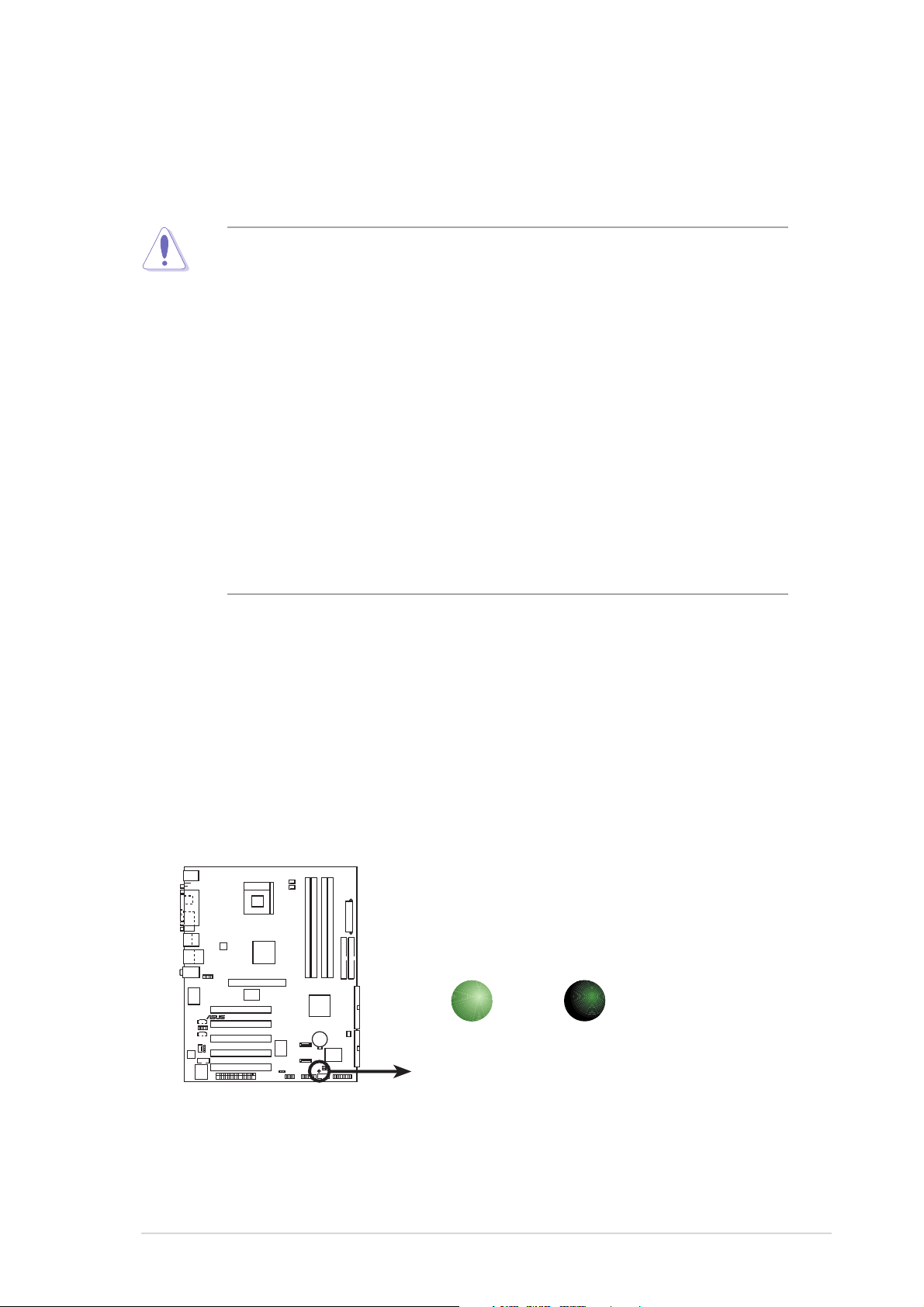
Onboard LED
The P4R800-V Deluxe motherboard comes with a standby power LED.
When lit, the green LED (SB_PWR) indicates that the system is ON, in
sleep mode, or in soft-off mode, a reminder that you should shut down the
system and unplug the power cable before removing or plugging in any
motherboard component.
ON
Standby
Power
SB_PWR
OFF
Powere
Off
P4R800-V
DELUXE
P4R800-V DELUXE Onboard LED
ASUS P4R800-V Deluxe motherboard user guide
2-1
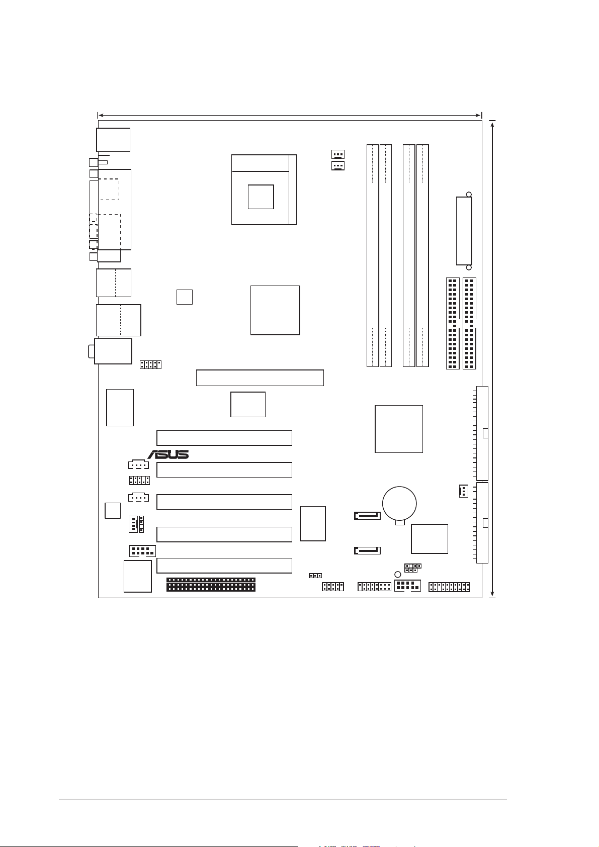
2.2 Motherboard layout
®
24.5cm (9.6in)
PS/2KBMS
T: Mouse
B: Keyboard
Composite
S-VHS
PARALLEL PORT
Socket 478
CPU_FAN
PWR_FAN
VGA
Bottom:
Top:
USB1
1394
USB2
USB2.0
Top:
T: USB3
RJ-45
B: USB4
Top:Line In
Center:Line Out
Below:Mic In
VIA
AUX
CD
AD1888
MODEM
COM2
IE1394_1
VT6307
FP_AUDIO
SPDIF_OUT
LPC
4Mbit
ATX12V1
Accelerated Graphics Port (AGP1)
PCI1
PCI2
PCI3
PCI4
PCI5
RADEON™
9100 IGP
P4R800-V
Marvell
88E001
WIFI
ATI
DELUXE
SiS
USBPW56
180
USB56
DDR DIMM_A2 (64 bit,184-pin module)
DDR DIMM_A1 (64 bit,184-pin module)
DDR DIMM_B2 (64 bit,184-pin module)
DDR DIMM_B1 (64 bit,184-pin module)
PRI_IDE
SEC_IDE
ATI
IXP150
SATA_RAID2
SATA_RAID1
GAME
CR2032 3V
Lithium Cell
CMOS Power
SB_PWR
COM1
Super
I/O
CHASSIS
CLRTC
CHA_FAN
PANEL
ATX Power Connector
30.5cm (12.0in)
PRI_RAID
FLOPPY
2-2
Chapter 2: Hardware information
2.2.1 Major components
Components Description Page
Sockets/Slots
Socket 478 Intel Pentium® 4/Celeron socket 2-5
DIMMs System memory socket 2-11
AGP Accelerated Graphics Port 2-16
PCI 32-bit PCI expansion slots 2-16
WIFI Wireless Fidelity slot 2-17
Jumpers
CLRTC Clear RTC RAM jumper 2-18
USBPWR56 USB Wake-up jumpers 2-19
Rear panel connectors
KBMS 6-pin PS/2 mouse port (green) 2-20
KBMS 6-pin PS/2 keyboard port (purple) 2-21
IEEE 1394 6-pin IEEE 1394 port 2-20
Parallel 25-pin parallel port 2-20
RJ-45 Local Area Network (LAN) port 2-20
Line In 1/8 inch Line in port (light blue) 2-20
Line out 1/8 inch Line out port (lime) 2-20
Microphone 1/8 inch Microphone port (pink) 2-20
USB 1 and 2 4-pin USB 2.0 ports 2-21
USB 3 and 4 4-pin USB 2.0 ports 2-21
VGA VGA port 2-21
TV_S S-Video port 2-21
TV_C RCA (composite) port (yellow) 2-21
Internal connectors
FLOPPY 34-1 Floppy disk drive connector 2-21
PRI_IDE/SEC_IDE 40-1 IDE connectors 2-22
GAME 16-1 GAME/MIDI connector 2-22
SATA_RAID1/SATA _RAID2 7-pin Serial ATA RAID connector 2-23
PRI_RAID 40-1 Primary RAID connector 2-23
COM1/COM2 10-1 pin Serial connector 2-24
CHASSIS 4-1 pin Chassis intrusion connector 2-24
IE1394_1 10-1 pin IEEE 1394 connector 2-25
SPDIF_OUT 3-pin S/PDIF Out connector 2-25
ATX12V 4-pin 12V ATX power supply connector 2-26
ATXPWR 20-pin ATX power supply connector 2-26
USB56 10-1 USB 2.0 connector 2-27
CD/AUX/MODEM 4-pin CD/Auxilliary/Modem connectors 2-27
CHA_FAN/CPU_FAN/PWR_FAN 3-pin Chassis/CPU/Power connectors 2-28
FP_AUDIO 10-1 pin Front Audio connector 2-28
PANEL 10-1 pin Panel connector 2-29
ASUS P4R800-V Deluxe motherboard user guide
2-3
2.2.2 Placement direction
When installing the motherboard, make sure that you place it into the
chassis in the correct orientation. The edge with external ports goes to the
rear part of the chassis as indicated in the image below.
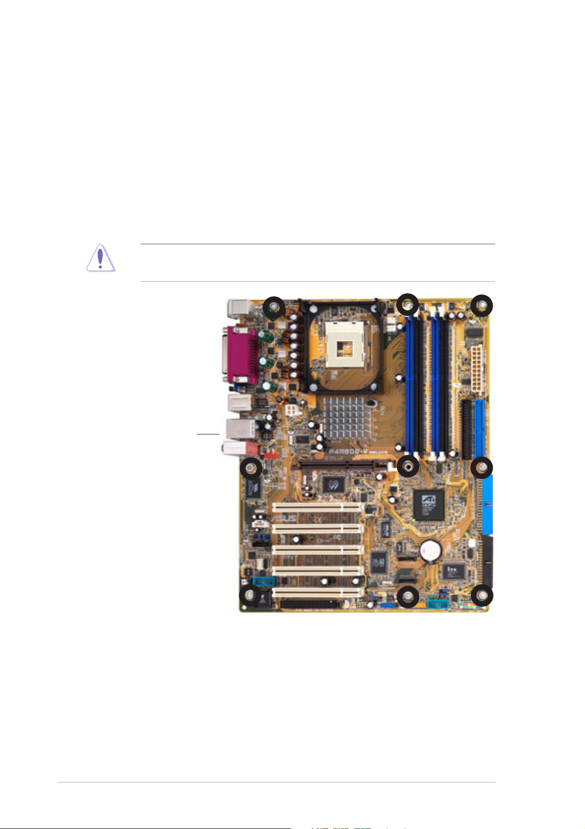
2.2.3 Screw holes
Place nine (9) screws into the holes indicated by circles to secure the
motherboard to the chassis.
Do not overtighten the screws! Doing so may damage the
motherboard.
Place this side towards
the rear of the chassis
2-4
Chapter 2: Hardware information
2.3 Central Processing Unit (CPU)
®
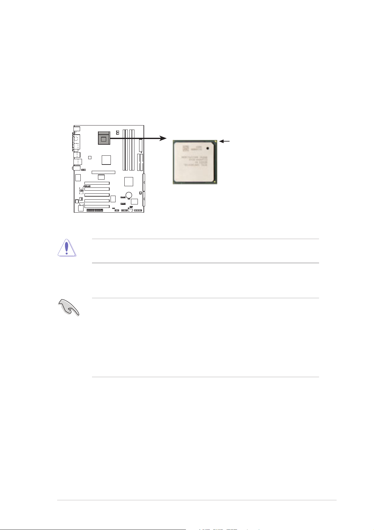
2.3.1 Overview
The Intel® Pentium® CPU has a gold triangular mark on one corner. This
mark indicates the processor Pin 1 that should match a specific corner of
the CPU socket.
Gold Arrow
P4R800-V
DELUXE
P4R800-V DELUXE Socket 478
Incorrect installation of the CPU into the socket may bend the pins and
severely damage the CPU!
Notes on Intel® Hyper-Threading Technology
1. Hyper-Threading Technology is supported under Windows® XP and
later versions only. If you are using any other operating systems,
disable the Hyper-Threading Techonology item in BIOS to ensure
system stability and performance.
2. It is recommended that you install Windows
3. For more information on Hyper-Threading Technology, visit
www.intel.com/info/hyperthreading.
®
XP Service Pack 1.
ASUS P4R800-V Deluxe motherboard user guide
2-5

2.3.2 Installing the CPU
0
Follow these steps to install a CPU.
1. Locate the
478-pin ZIF
socket on the
motherboard.
2. Unlock the socket by pressing the
lever sideways, then lift it up to a
90°-100° angle.
Socket Lever
90 -10
Make sure that the socket
lever is lifted up to 90°-100°
angle, otherwise the CPU
does not fit in completely.
3. Position the CPU above the
socket such that its marked
corner matches the base of the
socket lever.
4. Carefully insert the CPU into the
socket until it fits in place.
Gold Mark
2-6
The CPU fits only in one correct orientation. DO NOT force the CPU
into the socket to prevent bending the pins and damaging the CPU!
Chapter 2: Hardware information
5. When the CPU is in place, push
down the socket lever to secure
the CPU. The lever clicks on the
side tab to indicate that it is
locked.
2.3.3 Installing the heatsink and fan
The Intel® Pentium® 4 processor requires a specially designed heatsink
and fan assembly to ensure optimum thermal condition and performance.
• When you buy a boxed Inte® Pentium® 4 processor, the package
includes the heatsink, fan, and retention mechanism. In case you
buy a CPU separately, make sure that you use only Intel® certified
heatsink and fan.
®
• Your boxed Intel
installation instructions for the CPU, heatsink, and the retention
mechanism. If the instructions in this section do not match the CPU
documentation, follow the latter.
Pentium® 4 processor package should come with
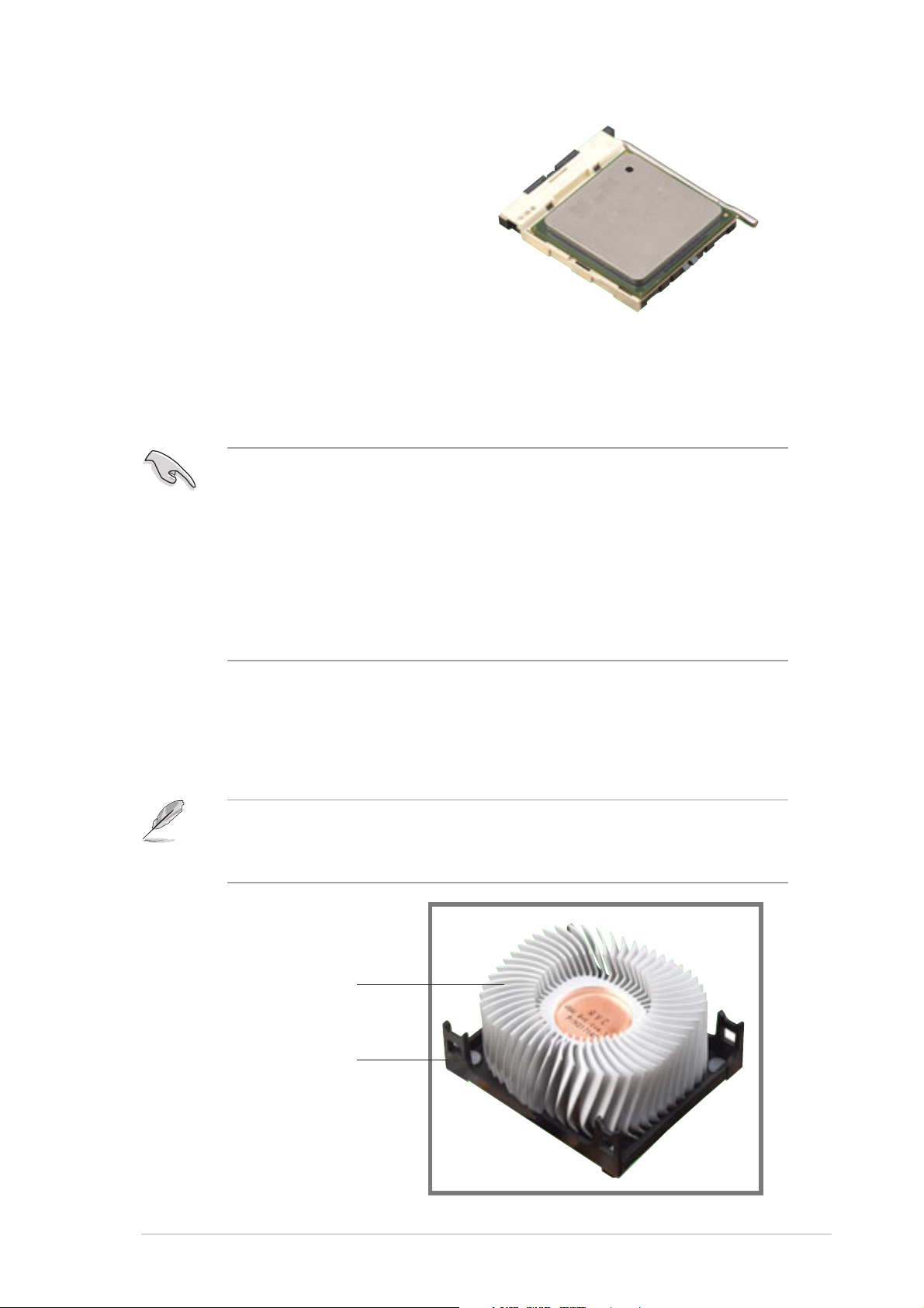
Follow these steps to install the CPU heatsink and fan.
1. Place the heatsink on top of the installed CPU, making sure that the
heatsink fits properly on the retention module base.
The retention module base is already installed on the motherboard
upon purchase. You do not have to remove the retention module base
when installing the CPU or installing other motherboard components.
CPU Heatsink
Retention Module Base
ASUS P4R800-V Deluxe motherboard user guide
2-7
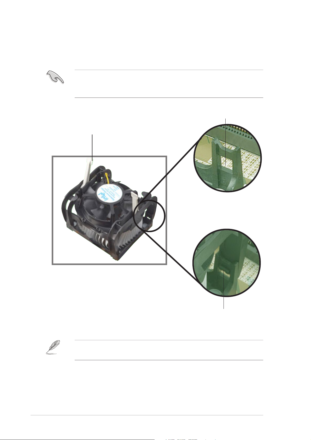
2. Position the fan with the retention mechanism on top of the heatsink.
Align and snap the four hooks of the retention mechanism to the holes
on each corner of the module base.
Make sure that the fan and retention mechanism assembly perfectly
fits the heatsink and module base, otherwise you cannot snap the
hooks into the holes.
Retention Hole
Retention Lock
2-8
Retention Hook Snapped
to the Retention Hole
Keep the retention locks lifted upward while fitting the retention
mechanism to the module base.
Chapter 2: Hardware information
 Loading...