

Page 1
Doc. No:
Authorize
Review
Originator
ASUSTeK
COMPUTER INC.
Rev. Modification
V101
English CSC
Vega2 M930 Assembly &
Disassembly SOP
Modify description Issue div. Originator
Date: 2008.2.26
Revision:
Page: Grade:
VEGA II M930 Assembly & Disassembly
SOP
by
by
by
Form No : D2-001-11 Rev.01
Page 2
ASUSTeK COMPUTER INC.
Doc. No:
Pegasus P Assembly & Disassembly
SOP
Date:
Rev.: Page:
1
Disassembly / Assembly Procedure
Introduction
This section describes how to disassemble PDA P527. Many of the integrated devices used in
this phone are vulnerable to damage. Ensure adequate static protection is in place when
handling, shipping, and servicing any internal components.
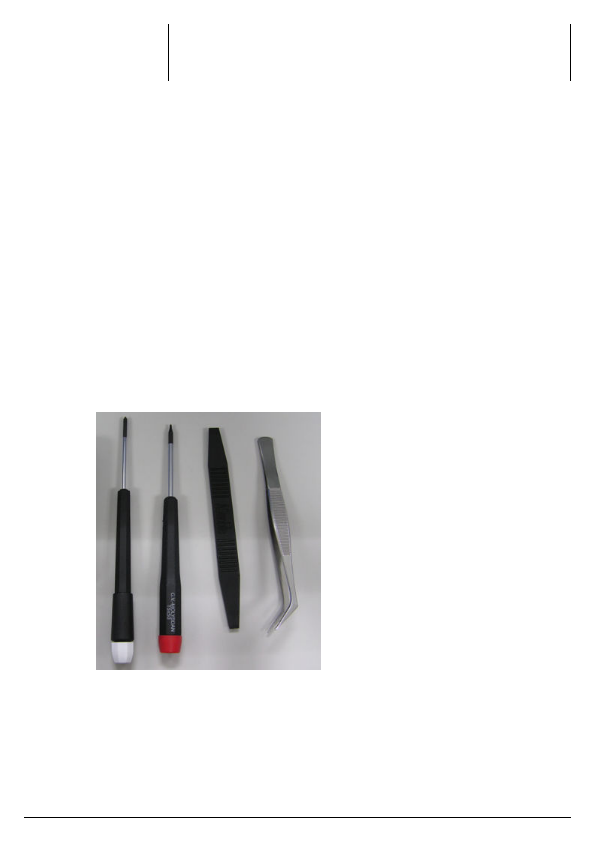
Recommended Tools
Anti-Static Mat (Ground Cord included)
Anti-Static Wrist Strap
Torque Screw Driver (T5 type, torque is set to 1.2kg-cm)
Tweezers
Plastic blade
Page 3
ASUSTeK COMPUTER INC.
Doc. No:
Pegasus P Assembly & Disassembly
SOP
Date:
Rev.: Page:
2
Disassembly procedu
The following set of diagrams will demonstrate the correct sequence and action to disassemble M930.
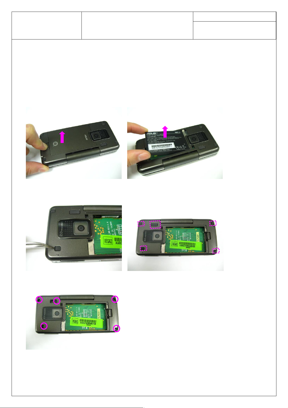
Step 1
Remove the battery cover and take the battery away.
Step 2
Remove five screw caps on case4 by a pair of tweezers and then remove 5 screws by a screw driver.
Step 3
Release the Case4 by a plastic blade and the take it off by hand.
slot. You can push to release them by the plastic blade.
Pay attention to the 2 hooks in battery
Page 4
ASUSTeK COMPUTER INC.
Doc. No:
Pegasus P Assembly & Disassembly
SOP
Date:
Rev.: Page:
3
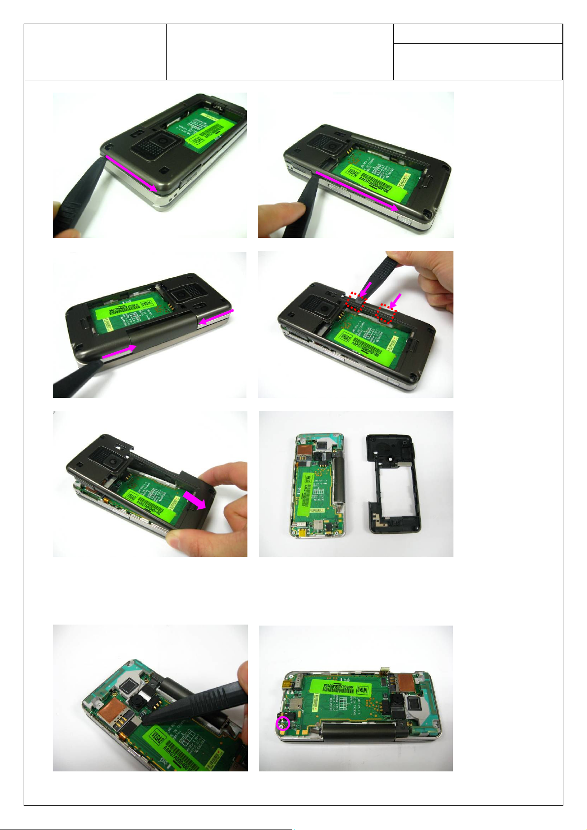
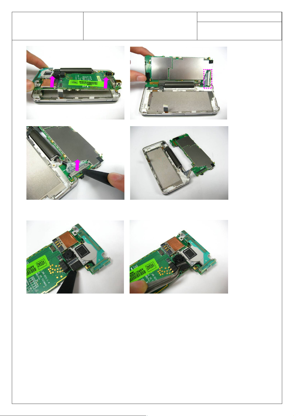
Step 4
Disconnect the keypad FPC by a plastic blade. Remove 1 screw on main board. Lift up the main board
and turn it over. Disconnect the coaxial cable and take away the main board.
Page 5
ASUSTeK COMPUTER INC.
Doc. No:
Pegasus P Assembly & Disassembly
SOP
Date:
Rev.: Page:
4
Step 5
Disconnect the CMOS and remove it from main board.
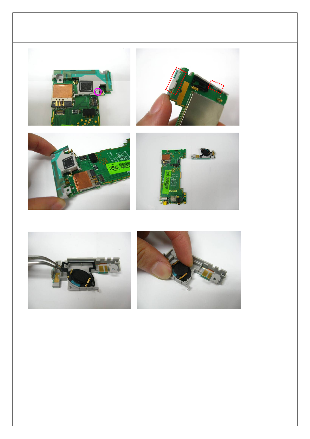
Step 6
Remove 1 screw on antenna holder and remove the antenna holder from main board. Pay attention to the
hooks on the back of the main board. Release the hooks first before removing the holder.
Page 6
ASUSTeK COMPUTER INC.
Doc. No:
Pegasus P Assembly & Disassembly
SOP
Date:
Rev.: Page:
5
Step 7
Take off the air sealed rubber and the speaker from the antenna holder.
Step 8
Remove the MIC rubber.
Page 7
ASUSTeK COMPUTER INC.
Doc. No:
Pegasus P Assembly & Disassembly
SOP
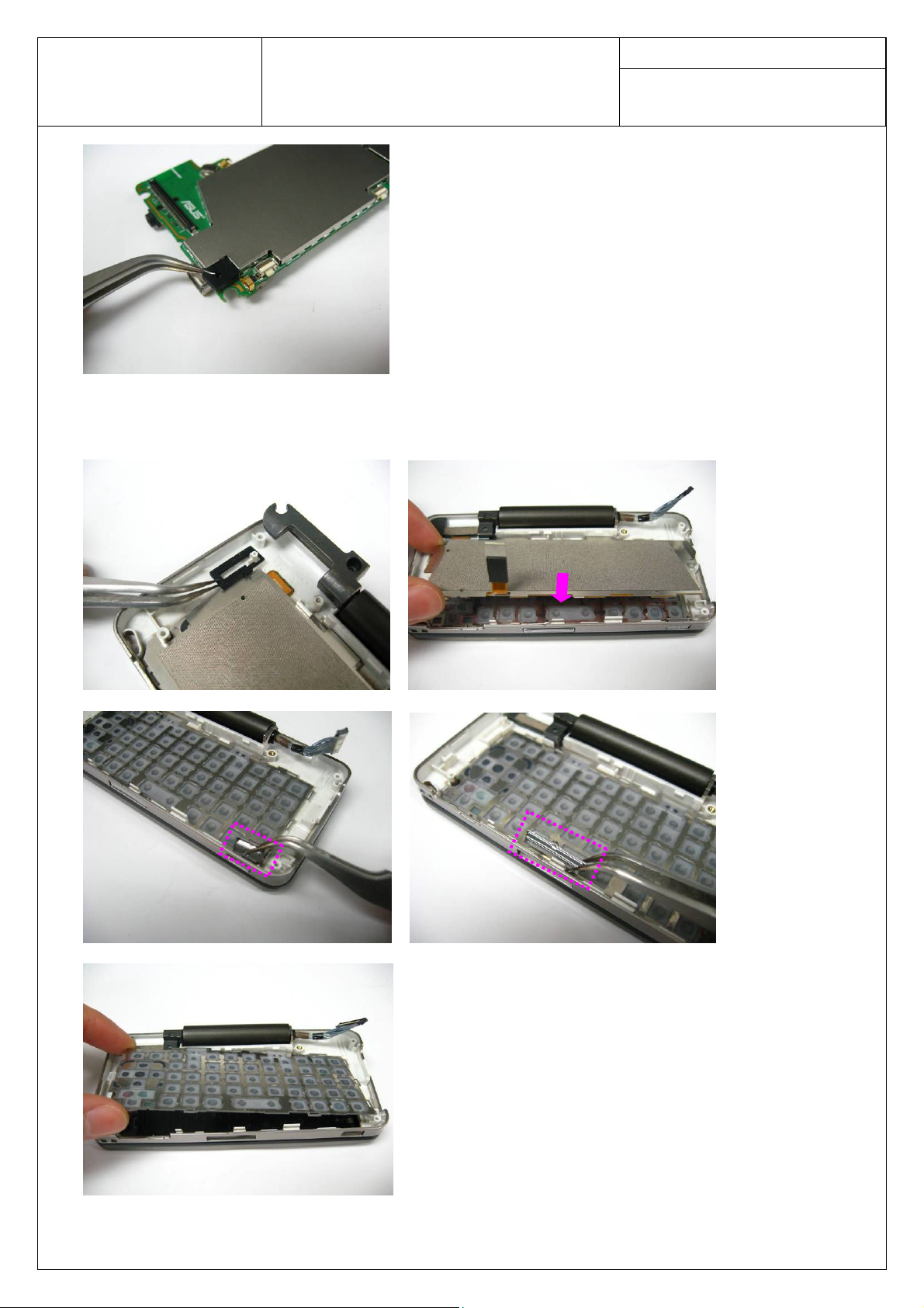
Step 9
Take off the Case3 sealed rubber and keypad FPC. Then remove the shutter key and side key. Take away
the keypad in Case3 at last.
Date:
Rev.: Page:
6
Step 10
Page 8

ASUSTeK COMPUTER INC.
Doc. No:
Pegasus P Assembly & Disassembly
SOP
Lift up the Case3 and release it. Then convolve the coaxial cable gently and push it through the hole of
Case3.
Please do not break off the cable when you convolve.
Date:
Rev.: Page:
7
Step 11
Remove 2 flip screw caps. Tear off the main lens using the pair of tweezers and plastic blade because of
the hard adhesive.
Page 9

ASUSTeK COMPUTER INC.
Doc. No:
Pegasus P Assembly & Disassembly
SOP
Step 12
Remove the VGA sponge. Remove the Case2 BTB supporter and disconnect the flip keypad FPC.
Remove 4 screws on Case2.
Date:
Rev.: Page:
8
Step 13
Release the Case2 from the hooks and separate the Case2 from Case1.
Page 10

ASUSTeK COMPUTER INC.
Doc. No:
Pegasus P Assembly & Disassembly
SOP
Step 14
Open the VGA connector and remove the CMOD sensor module.
Step 15
Tear off the Flip PCB Mylar and Coaxial Cable Mylar and then release the LCD board from its hooks.
Disconnect the coaxial cable, LCD FPC, LCM FPC on LCD board. Take the LCD board away.
Date:
Rev.: Page:
9
Page 11

ASUSTeK COMPUTER INC.
LCD FPC
Coaxial
Cable
LCM FPC
Doc. No:
Pegasus P Assembly & Disassembly
SOP
Step 16
Take off the LCM module.
Date:
Rev.: Page:
10
Step 17
Release the LCD FPC then separate the LCD FPC from case1.
of case2.
Pay attention to the 3 hooks at the back
Page 12

ASUSTeK COMPUTER INC.
Doc. No:
Pegasus P Assembly & Disassembly
SOP
Step 18
Release the coaxial cable from its hook on Case2 and convolve the coaxial cable gently. Pull out the
cable slightly from Case2.
Date:
Rev.: Page:
11
Step 19
Page 13

ASUSTeK COMPUTER INC.
Doc. No:
Pegasus P Assembly & Disassembly
SOP
Remove the sub LCM frame from the Case1. (Because of the hard adhesive you may need to separate it
hardly.)
Remove the flip keypad and LCD keypad. Then remove the receiver from Case1.
Date:
Rev.: Page:
12
Assembly Procedure
It is carried out in the exact reverse sequence as the disassembly.
Step 1
Install the receiver to on case1 by a pair of tweezers. Install the flip keypad and LCD keypad on Case1.
Then install the sub LCM frame.
Page 14

ASUSTeK COMPUTER INC.
Doc. No:
Pegasus P Assembly & Disassembly
SOP
Date:
Rev.: Page:
13
Step 2
Convolve the coaxial cable and assemble it on Case2.
Page 15

ASUSTeK COMPUTER INC.
Doc. No:
Pegasus P Assembly & Disassembly
SOP
Date:
Rev.: Page:
14
Step 3
Install the LCD FPC on Case2. Fix the FPC on Case2.
fix it on Case2.
Pay attention to the hooks of LCD FPC. Press to
Step 4
Install the LCM module.
Page 16

ASUSTeK COMPUTER INC.
LCD FPC
LCM FPC
Doc. No:
Pegasus P Assembly & Disassembly
SOP
Step 5
Connect the LCM FPC, LCD FPC and Coaxial Connector with LCD board. Then install the LCD board
on Case2.
Fix it into the hooks. Then paste the Coaxial Cable Mylar and Flip PCB Mylar.
Date:
Rev.: Page:
15
Step 6
Page 17

ASUSTeK COMPUTER INC.
Doc. No:
Pegasus P Assembly & Disassembly
SOP
Install the CMOS sensor module.
Step 7
Assemble the Case2 with Case1 and
Connect the Flip keypad FPC and install the Case2 BTB supporter. Then fix the VGA sponge.
press four sides to fix it into the hooks. Then secure 4 screws.
Date:
Rev.: Page:
16
Step 8
Page 18

ASUSTeK COMPUTER INC.
Doc. No:
Pegasus P Assembly & Disassembly
SOP
Paste the main lens and 2 flip screw caps.
Step 9
Install the Case3. Convolve the coaxial cable gently and pull it though the Case3.
the hinge. You may turn it as the picture shows before assemble the case3 under it.
Date:
Rev.: Page:
Then pay attention to
17
Step 10
Page 19

ASUSTeK COMPUTER INC.
Doc. No:
Pegasus P Assembly & Disassembly
SOP
Assemble the keypad, side key and shutter key. Then install the keypad FPC.
Date:
Rev.: Page:
18
Step 11
Assemble the case3 sealed rubber. Turn the hinge as the picture shows.
Step 12
s
Page 20

ASUSTeK COMPUTER INC.
Doc. No:
Pegasus P Assembly & Disassembly
SOP
Install the MIC rubber.
Step 13
Install the speaker and the air sealed rubber.
Date:
Rev.: Page:
19
Step 14
Install the antenna and fix it into the hooks. Then secure 1 screw on it.
Page 21

ASUSTeK COMPUTER INC.
Doc. No:
Pegasus P Assembly & Disassembly
SOP
Step 15
Install the CMOS on main board.
Step 16
Connect the coaxial cable with main board and install the main board in Case3.
the main board into the hooks
with main board.
and secure 1 screw on it. Pay attention to keypad FPC, connect the FPC
Date:
Rev.: Page:
Press four sides to fix
20
Page 22

ASUSTeK COMPUTER INC.
Doc. No:
Pegasus P Assembly & Disassembly
SOP
Step 17
Assemble the Case4. Press four sides to fix the case into its hooks.
Date:
Rev.: Page:
21
Step 18
Secure 5 screws and fix 5 screw caps.
Step 19
Install the battery and battery case.
 Loading...