

Page 1

M4A78 PRO
Motherboard
Page 2

E4341
First Edition V1
December 2008
Copyright © 2008 ASUSTeK Computer Inc. All Rights Reserved.
No part of this manual, including the products and software described in it, may be reproduced,
transmitted, transcribed, stored in a retrieval system, or translated into any language in any form or by any
means, except documentation kept by the purchaser for backup purposes, without the express written
permission of ASUSTeK Computer Inc. (“ASUS”).
Product warranty or service will not be extended if: (1) the product is repaired, modied or altered, unless
such repair, modication of alteration is authorized in writing by ASUS; or (2) the serial number of the
product is defaced or missing.
ASUS PROVIDES THIS MANUAL “AS IS” WITHOUT WARRANTY OF ANY KIND, EITHER EXPRESS
OR IMPLIED, INCLUDING BUT NOT LIMITED TO THE IMPLIED WARRANTIES OR CONDITIONS OF
MERCHANTABILITY OR FITNESS FOR A PARTICULAR PURPOSE. IN NO EVENT SHALL ASUS, ITS
DIRECTORS, OFFICERS, EMPLOYEES OR AGENTS BE LIABLE FOR ANY INDIRECT, SPECIAL,
INCIDENTAL, OR CONSEQUENTIAL DAMAGES (INCLUDING DAMAGES FOR LOSS OF PROFITS,
LOSS OF BUSINESS, LOSS OF USE OR DATA, INTERRUPTION OF BUSINESS AND THE LIKE),
EVEN IF ASUS HAS BEEN ADVISED OF THE POSSIBILITY OF SUCH DAMAGES ARISING FROM ANY
DEFECT OR ERROR IN THIS MANUAL OR PRODUCT.
SPECIFICATIONS AND INFORMATION CONTAINED IN THIS MANUAL ARE FURNISHED FOR
INFORMATIONAL USE ONLY, AND ARE SUBJECT TO CHANGE AT ANY TIME WITHOUT NOTICE,
AND SHOULD NOT BE CONSTRUED AS A COMMITMENT BY ASUS. ASUS ASSUMES NO
RESPONSIBILITY OR LIABILITY FOR ANY ERRORS OR INACCURACIES THAT MAY APPEAR IN THIS
MANUAL, INCLUDING THE PRODUCTS AND SOFTWARE DESCRIBED IN IT.
Products and corporate names appearing in this manual may or may not be registered trademarks or
copyrights of their respective companies, and are used only for identication or explanation and to the
owners’ benet, without intent to infringe.
ii
Page 3

Contents
Contents ...................................................................................................... iii
Notices ......................................................................................................... vi
Safety information ..................................................................................... vii
About this guide ........................................................................................ vii
M4A78 PRO specications summary ....................................................... ix
Chapter 1 Product introduction
1.1 Welcome! ...................................................................................... 1-1
1.2 Package contents ......................................................................... 1-1
1.3 Special features ............................................................................ 1-1
1.3.1 Product highlights ........................................................... 1-1
1.3.2 Innovative ASUS features ............................................... 1-2
1.4 Before you proceed ..................................................................... 1-4
1.5 Motherboard overview ................................................................. 1-5
1.5.1 Placement direction ........................................................ 1-5
1.5.2 Screw holes .................................................................... 1-5
1.5.3 Motherboard layout ......................................................... 1-6
1.5.4 Layout contents ............................................................... 1-6
1.6 Central Processing Unit (CPU) ................................................... 1-7
1.6.1 Installing the CPU ........................................................... 1-7
1.6.2 Installing the heatsink and fan ........................................ 1-8
1.7 System memory ......................................................................... 1-10
1.7.1 Overview ....................................................................... 1-10
1.7.2 Memory congurations .................................................. 1-10
1.7.3 Installing a DIMM .......................................................... 1-15
1.7.4 Removing a DIMM ........................................................ 1-15
1.8 Expansion slots .......................................................................... 1-16
1.8.1 Installing an expansion card ......................................... 1-16
1.8.2 Conguring an expansion card ..................................... 1-16
1.8.3 PCI slots ........................................................................ 1-16
1.8.4 PCI Express x1 slots ..................................................... 1-16
1.8.5 PCI Express x16 slot ..................................................... 1-16
1.9 Jumpers ...................................................................................... 1-17
1.10 Connectors ................................................................................. 1-19
1.10.1 Rear panel connectors .................................................. 1-19
1.10.2 Internal connectors ....................................................... 1-22
iii
Page 4

Contents
1.11 Software support ........................................................................ 1-31
1.11.1 Installing an operating system ...................................... 1-31
1.11.2 Support DVD information .............................................. 1-31
Chapter 2 BIOS information
2.1 Managing and updating your BIOS ............................................ 2-1
2.1.1 Creating a bootable oppy disk ....................................... 2-1
2.1.2 ASUS Update utility ........................................................ 2-2
2.1.3 ASUS EZ Flash 2 utility ................................................... 2-3
2.1.4 AFUDOS utility ................................................................ 2-4
2.1.5 ASUS CrashFree BIOS 3 utility ...................................... 2-5
2.2 BIOS setup program .................................................................... 2-6
2.2.1 BIOS menu screen .......................................................... 2-7
2.2.2 Menu bar ......................................................................... 2-7
2.2.3 Navigation keys ............................................................... 2-8
2.2.4 Menu items ..................................................................... 2-8
2.2.5 Submenu items ............................................................... 2-8
2.2.6 Conguration elds ......................................................... 2-8
2.2.7 General help ................................................................... 2-8
2.2.8 Pop-up window ............................................................... 2-8
2.2.9 Scroll bar ......................................................................... 2-8
2.3 Main menu .................................................................................... 2-9
2.3.1 System Time ................................................................... 2-9
2.3.2 System Date ................................................................... 2-9
2.3.3 Legacy Diskette A ........................................................... 2-9
2.3.4 Primary IDE Master/Slave ............................................... 2-9
2.3.5 SATA 1–6 ..................................................................... 2-10
2.3.6 Storage Conguration ....................................................2-11
2.3.7 System Information ........................................................2-11
2.4 Ai Tweaker menu ........................................................................ 2-12
2.4.1 AI Overclocking ............................................................ 2-12
2.4.2 DRAM Frequency Control ............................................ 2-12
2.4.3 HT Link Speed ............................................................. 2-13
2.4.4 Processor Voltage ........................................................ 2-15
2.4.5 CPU/NB Voltage .......................................................... 2-15
2.4.6 CPU VDDA Voltage ...................................................... 2-16
iv
Page 5

Contents
2.4.7 DRAM Voltage ............................................................. 2-16
2.4.8 HT Voltage ................................................................... 2-16
2.4.9 NB Voltage ................................................................... 2-16
2.4.10 NB 1.8V Voltage ........................................................... 2-16
2.4.11 SB Voltage ................................................................... 2-16
2.4.12 CPU Spread Spectrum ................................................ 2-16
2.4.13 PCIE Spread Spectrum ................................................ 2-16
2.4.14 SB Clock Spread Spectrum .......................................... 2-16
2.5 Advanced menu ......................................................................... 2-17
2.5.1 CPU Conguration ........................................................ 2-17
2.5.2 Chipset .......................................................................... 2-18
2.5.3 Onboard Devices Conguration .................................... 2-20
2.5.4 USB Conguration ........................................................ 2-21
2.6 Power menu ................................................................................ 2-21
2.6.1 Suspend Mode ............................................................. 2-22
2.6.2 Repost Video on S3 Resume ........................................ 2-22
2.6.3 ACPI 2.0 Support .......................................................... 2-22
2.6.4 ACPI APIC Support ...................................................... 2-22
2.6.5 APM Conguration ........................................................ 2-22
2.6.6 Hardware Monitor ......................................................... 2-23
2.7 Boot menu .................................................................................. 2-24
2.7.1 Boot Device Priority ...................................................... 2-24
2.7.2 Boot Settings Conguration .......................................... 2-24
2.7.3 Security ......................................................................... 2-25
2.8 Tools menu ................................................................................. 2-26
2.8.1 ASUS EZ Flash 2 .......................................................... 2-26
2.8.2 Express Gate ............................................................... 2-26
2.8.3 ASUS O.C. Prole ......................................................... 2-27
2.8.4 AI NET 2........................................................................ 2-27
2.9 Exit menu .................................................................................... 2-28
v
Page 6

Notices
Federal Communications Commission Statement
This device complies with Part 15 of the FCC Rules. Operation is subject to the following two
conditions:
• This device may not cause harmful interference, and
• This device must accept any interference received including interference that may cause
undesired operation.
This equipment has been tested and found to comply with the limits for a Class B digital
device, pursuant to Part 15 of the FCC Rules. These limits are designed to provide
reasonable protection against harmful interference in a residential installation. This
equipment generates, uses and can radiate radio frequency energy and, if not installed
and used in accordance with manufacturer’s instructions, may cause harmful interference
to radio communications. However, there is no guarantee that interference will not occur
in a particular installation. If this equipment does cause harmful interference to radio or
television reception, which can be determined by turning the equipment off and on, the user
is encouraged to try to correct the interference by one or more of the following measures:
•
Reorient or relocate the receiving antenna.
•
Increase the separation between the equipment and receiver.
•
Connect the equipment to an outlet on a circuit different from that to which the receiver is
connected.
•
Consult the dealer or an experienced radio/TV technician for help.
The use of shielded cables for connection of the monitor to the graphics card is required
to assure compliance with FCC regulations. Changes or modications to this unit not
expressly approved by the party responsible for compliance could void the user’s authority
to operate this equipment.
Canadian Department of Communications Statement
This digital apparatus does not exceed the Class B limits for radio noise emissions from
digital apparatus set out in the Radio Interference Regulations of the Canadian Department
of Communications.
This class B digital apparatus complies with Canadian ICES-003.
DO NOT throw the motherboard in municipal waste. This product has been designed to
enable proper reuse of parts and recycling. This symbol of the crossed out wheeled bin
indicates that the product (electrical and electronic equipment) should not be placed in
municipal waste. Check local regulations for disposal of electronic products.
DO NOT throw the mercury-containing button cell battery in municipal waste. This symbol
of the crossed out wheeled bin indicates that the battery should not be placed in municipal
waste.
vi
Page 7

Safety information
Electrical safety
•
To prevent electrical shock hazard, disconnect the power cable from the electrical outlet
before relocating the system.
•
When adding or removing devices to or from the system, ensure that the power cables
for the devices are unplugged before the signal cables are connected. If possible,
disconnect all power cables from the existing system before you add a device.
•
Before connecting or removing signal cables from the motherboard, ensure that all
power cables are unplugged.
•
Seek professional assistance before using an adapter or extension cord. These devices
could interrupt the grounding circuit.
•
Ensure that your power supply is set to the correct voltage in your area. If you are not
sure about the voltage of the electrical outlet you are using, contact your local power
company.
•
If the power supply is broken, do not try to x it by yourself. Contact a qualied service
technician or your retailer.
Operation safety
•
Before installing the motherboard and adding devices on it, carefully read all the manuals
that came with the package.
•
Before using the product, ensure that all cables are correctly connected and the power
cables are not damaged. If you detect any damage, contact your dealer immediately.
•
To avoid short circuits, keep paper clips, screws, and staples away from connectors,
slots, sockets and circuitry.
•
Avoid dust, humidity, and temperature extremes. Do not place the product in any area
where it may become wet.
•
Place the product on a stable surface.
•
If you encounter technical problems with the product, contact a qualied service
technician or your retailer.
About this guide
This user guide contains the information you need when installing and conguring the
motherboard.
How this guide is organized
This guide contains the following parts:
• Chapter 1: Product introduction
This chapter describes the features of the motherboard and the new technology it
supports.
• Chapter 2: BIOS setup
This chapter tells how to change system settings through the BIOS Setup menus.
Detailed descriptions of the BIOS parameters are also provided.
vii
Page 8

Conventions used in this guide
To ensure that you perform certain tasks properly, take note of the following symbols used
throughout this manual.
DANGER/WARNING: Information to prevent injury to yourselfInformation to prevent injury to yourself
when trying to complete a task.
CAUTION: Information to prevent damage to the componentsInformation to prevent damage to the components
when trying to complete a task.
IMPORTANT: Instructions that you MUST follow to complete a
task.
NOTE: Tips and additional information to help you complete aTips and additional information to help you complete a
task.
Where to nd more information
Refer to the following sources for additional information and for product and software
updates.
1. ASUS websites
The ASUS website provides updated information on ASUS hardware and software
products. Refer to the ASUS contact information.
2. Optional documentation
Your product package may include optional documentation, such as warranty yers,
that may have been added by your dealer. These documents are not part of the
standard package.
Typography
Bol d te xt Indicates a menu or an item to select.Indicates a menu or an item to select.
Italics
Used to emphasize a word or a phrase.
<Key> Keys enclosed in the less-than and greater-than sign means
that you must press the enclosed key.
Example: <Enter> means that you must press the Enter or
Return key.
<Key1>+<Key2>+<Key3> If you must press two or more keys simultaneously, the key
names are linked with a plus sign (+).
Example: <Ctrl>+<Alt>+<D>
Command Means that you must type the command exactly as shown,Means that you must type the command exactly as shown,
then supply the required item or value enclosed in
brackets.
Example: At the DOS prompt, type the command line:
afudos /iM4A78PRO.ROM
viii
Page 9

M4A78 PRO specications summary
CPU AMD® Phenom™ X4 / Phenom™ X3 / Athlon™ X2 /
Chipset AMD 780G / SB700
System bus Up to 5200 MT/s; HyperTransport™ 3.0 interface for
Memory Dual-channel memory architecture
VGA Integrated ATI Radeon™ HD 3200 GPU
Expansion Slots 1 x PCIe 2.0 x16 slot
Athlon™ / Sempron™ processors (socket AM2+/AM2)
Compatible with AMD® Phenom™ II / Athlon™ X4/
Athlon™ X3 / Athlon™ X2 (AM3 CPU)
AMD® 45nm CPU support
AMD Cool’n’Quiet™ Technology
AM3 / AM2+ CPU
2000 / 1600 MT/s for AM2 CPU
- 4 x 240-pin DIMM sockets support unbufferred
ECC / non-ECC DDR2 1066* / 800 / 667 MHz
memory modules
- Supports up to 16 GB system memory
*Due to AMD CPU limitation, DDR2 1066 is supported by
AM2+ / AM3 CPUs for one DIMM per channel only. Refer
to www.asus.com or this user manual for the Memory
QVL (Qualied Vendors Lists).
** Due to OS limitation, when installing total memory of
4GB capacity or more, Windows 32-bit operation
system may only recognize less than 3GB. Hence, a
total installed memory of less than 3GB is
recommended.
- Supports HDMI™ Technology with max. resolution up
to 1920 x 1080 (1080P)
- Supports Dual-link DVI with max. resolution up to
2560 x 1600 @ 60Hz
- Supports D-Sub with max. resolution up to 2560 x
1440 @ 75 Hz
- Hybrid CrossFireX™ support
HDMI / DVI / D-Sub support (Dual independent
displays support with HDMI / DVI and D-Sub)
- Supports Microsoft® DirectX 10, OpenGL 2.0, Pixel
Shader 4.0
- Hardware Decode Acceleration for H.264, VC-1, and
MPEG-2
- Maximum shared memory of 512MB
2 x PCIe x1 slots
3 x PCI 2.2 slots
(continued on the next page)
ix
Page 10

M4A78 PRO specications summary
Storage 1 x Ultra DMA 133/100/66 for up to 2 PATA devices
LAN Atheros® L1E Gigabit LAN controller featuring AI NET 2
High Denition Audio VIA1708S 8-channel High Denition Audio CODEC8-channel High Denition Audio CODEC
USB 12 x USB 2.0 /1.1 ports (8 at mid-board; 4 on the rear
ASUS Unique Features ASUS Power Solution:
Special Features Uses 100% All High-quality Conductive Polymer Capacitors!
6 x SATA 3.0 Gb/s connectors supporting RAID 0, 1, 10
and JBOD conguration
- Supports Jack-Detection and Multi-StreamingSupports Jack-Detection and Multi-StreamingMulti-Streaming
- Optical S/PDIF Out port at back I/OS/PDIF Out port at back I/O
- ASUS Noise Filter
panel)
- ASUS 4+1 Phase Power Design
- ASUS Anti-Surge Protection
ASUS Green Design:
- ASUS EPU
- ASUS AI Nap
ASUS Quiet Thermal Solution:
- ASUS Fanless Design: Feather heatsink solution
- ASUS Q-Fan 2
ASUS EZ DIY
- ASUS Express Gate
- ASUS Q-Connector
- ASUS CrashFree BIOS 3
- ASUS O.C. Prole
- ASUS EZ Flash 2
ASUS MyLogo 2™
AMD OverDrive Support*
* Advanced cooling system is required when advanced
overclock functions of AMD OverDrive are enabled.
(continued on the next page)
x
Page 11

M4A78 PRO specications summary
ASUS Exclusive
Overclocking Features
Rear panel I/O ports 1 x PS/2 keyboard port (purple)
Internal I/O connectors 4 x USB connectors support additional 8 USB ports
Intelligent overclocking tools:
- AI Overclocking (Intelligent CPU Frequency Tuner)
- ASUS TurboV
- ASUS Turbo Key
Precision Tweaker:
- vCore: Adjustable CPU voltage at 50mv
increment
- vDIMM: 8-step DRAM voltage control
- vChipset: 4-step Chipset voltage control
SFS (Stepless Frequency Selection):
- FSB tuning from 200MHz up to 600MHz at 1MHz
increment
- PCIe frequency tuning from 100MHz to 150MHz
at 1MHz increment
Overclocking protection:
- ASUS C.P.R. (CPU Parameter Recall)
1 x PS/2 mouse port (green)
1 x S/PDIF Out (Optical)
1 x HDMI Out
1 x D-Sub
1 x DVI
1 x LAN (RJ-45)
4 x USB 2.0/1.1
8-channel audio I/O
1 x Floppy disk drive connector
1 x COM connector
1 x IDE connector
6 x SATA connectors
1 x CPU Fan connector
1 x Chassis Fan connector
1 x Power Fan connector
1 x Front panel audio connector
1 x S/PDIF Out Header
1 x Chassis Intrusion connector
1 x CD audio in
1 x 24-pin ATX Power connector
1 x 4-pin ATX 12V Power connector
1 x System Panel (Q-Connector)
(continued on the next page)
xi
Page 12

M4A78 PRO specications summary
BIOS features 8 Mb Flash ROM, AMI BIOS, PnP, DMI 2.0, WfM2.0, SM
Support DVD contents Drivers
Form factor ATX form factor: 12 in x 9.6 in (30.5 cm x 24.4 cm)
*Specications are subject to change without notice.
BIOS 2.5, ACPI 2.0a, ASUS EZ Flash 2
Express Gate
ASUS PC Probe II
ASUS Update
AMD OverDrive Utility (AOD)
Anti-Virus Utility (OEM version)
xii
Page 13
Chapter 1
Product introduction
1.1 Welcome!
Thank you for buying an ASUS® M4A78 PRO motherboard!
The motherboard delivers a host of new features and latest technologies, making it another
standout in the long line of ASUS quality motherboards!
Before you start installing the motherboard, and hardware devices on it, check the items in
your package with the list below.
1.2 Package contents
Check your motherboard package for the following items.
Motherboard ASUS M4A78 PRO motherboard
Cables 1 x Serial ATA cable
2 x SATA cables
Accessories 1 x I/O shield
Application DVD ASUS motherboard support DVD
Documentations User manual
If any of the above items is damaged or missing, contact your retailer.
1.3 Special features
1.3.1 Product highlights
AMD® Phenom™ II / Athlon™ X4 / Athlon™ X3 / Athlon™ X2
Chapter 1: Product introduction 1-1
processors (socket AM3)
This motherboard supports AMD® AM3 multi-core processors with unique
L3 cache and delivers better overclocking capabilities with less power
consumption. It features dual-channel DDR2 1066 memory support and
accelerates data transfer rate up to 5200MT/s via HyperTransort™ 3.0
based system bus. This motherboard also supports AMD® CPUs in the
new 45nm manufacturing process.
AMD® Phenom™ X4 / Phenom™ X3 / Athlon™ X2 / Athlon™ /
Sempron™ processors (socket AM2+ / AM2)
The motherboard supports AMD® Socket AM2+ multi-core processors. It
features dual-channel DDR2 1066 memory support, data transfer rate up
to 5200MT/s via HyperTransport™ 3.0 based system bus and AMD®
Cool ‘n’ Quiet!™ Technology.
Page 14
AMD® 780G chipset
The AMD 780G Northbridge is the latest AMD chipset designed for both
HT1.0 and 5200MT/s HyperTransport™ 3.0 (HT 3.0) interface speed and
external graphics in PCI Express 2.0 standard. It features the integrated
ATI RV610-based graphics and fully Directx 10.0 compliant.
Dual channel DDR2 1066 support
This motherboard supports DDR2 1066, which provides faster data
transfer rate and more bandwidth to increase memory data transfer rate
and computing efciency. This enhances system performance in 3D
graphics and other memory demanding applications.
Due to AM2+ CPU limitation, only one DDR2 1066 is supported per channel. When four
DDR2 1066 DIMMs are installed, all DIMMs run at 800MHz frequency by default for
system stability.
AMD® Hybrid CrossFireX Technology
Hybrid CrossFireX Technology is a unique multi-GPU technology
combining the onboard GPU and the discrete graphics card together to
enhance 3D graphics performance.
Visit www.amd.com for the Hybrid CrossreX selected GPUs.
1.3.2 Innovative ASUS features
ASUS Power Solution
ASUS 4+1 Phase Power Design
To fully unleash the next-generation AM3 CPU’s potential, ASUS M4A78
PRO motherboard has adopted a brand-new 4-phase VRM power
design. It delivers high power efciency and supreme overclocking ability.
Furthermore, high quality power components can effective lower system
temperature to ensure longer component lifespan. ASUS M4A78 PRO also
features an extra 1-phase power for integrated memory/HT controller to
provide independent power to vital components.
ASUS EPU
The ASUS EPU (Energy Processing Unit) provides total system energy
efciency by detecting current PC loadings and intelligently moderating
power in real-time. It automatically provides the most appropriate power
usage for the CPU, VGA card, memory, chipset, hard drives, and system
fans—helping save power and money!
ASUS Anti-Surge
This special design prevents expensive devices and the motherboard from
damage caused by lighting strikes or power surges.
1-2 ASUS M4A78 PRO
Page 15
AI Nap
With AI Nap, the system can continue running at minimum power and
noise when you are temporarily away. To wake the system and return to
the OS environment, simply click the mouse or press a key.
ASUS EZ O.C.
ASUS TurboV
Feel the adrenaline rush of real-time O.C.—now a reality with the ASUS
TurboV. This easy O.C. tool allows you to overclock without exiting or
rebooting the OS: and its user-friendly interface makes overclock with ust
a few clicks away. More, the ASUS OC Proles in TurboV provides the
best O.C. settings in different scenarios.
ASUS Turbo Key
ASUS Turbo Key allows the user to turn the PC power button into a
physical overclocking button. After the easy setup, Turbo Key can boost
performances without interrupting ongoing work or games—with just one
touch!
Other ASUS Features
ASUS Express Gate
Taking only 5 seconds to bootup, Express Gate is the one-stop gateway
to instant fun! It’s a unique motherboard built-in OS. You can utilize the
most popular Instant Messengers (IM) like MSN, Skype, Google talk, QQ,
and Yahoo! Messenger to keep in touch with friends, or quickly check on
the weather and e-mails just before leaving your house. What’s more, the
user-friendly picture manager lets you view your pictures without entering
Windows at anytime!
The actual boot time depends on the system conguration.
Chapter 1: Product introduction 1-3
Page 16
1.4 Before you proceed
Take note of the following precautions before you install motherboard components or change
any motherboard settings.
• Unplug the power cord from the wall socket before touching any component.
• Before handling components, use a grounded wrist strap or touch a safely grounded
object or a metal object, such as the power supply case, to avoid damaging them due to
static electricity.
• Hold components by the edges to avoid touching the ICs on them.
• Whenever you uninstall any component, place it on a grounded antistatic pad or in the
bag that came with the component.
• Before you install or remove any component, switch off the ATX power supply and
detach its power cord. Failure to do so may cause severe damage to the motherboard,
peripherals, or components.
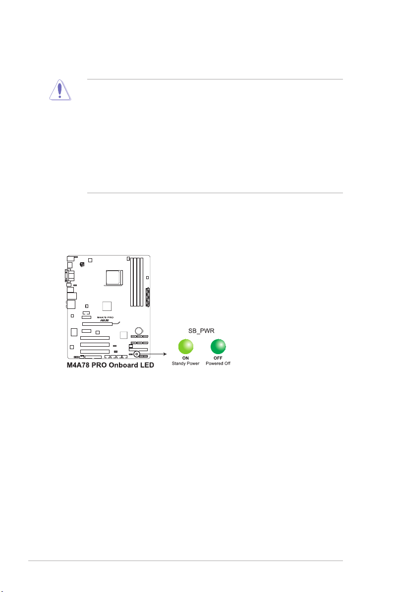
Onboard LED
The motherboard comes with a standby power LED that lights up to indicate that the system
is ON, in sleep mode, or in soft-off mode. This is a reminder that you should shut down
the system and unplug the power cable before removing or plugging in any motherboard
component. The illustration below shows the location of the onboard LED.
1-4 ASUS M4A78 PRO
Page 17
1.5 Motherboard overview
1.5.1 Placement direction
When installing the motherboard, ensure that you place it into the chassis in the correct
orientation. The edge with external ports goes to the rear part of the chassis as indicated in
the image below.
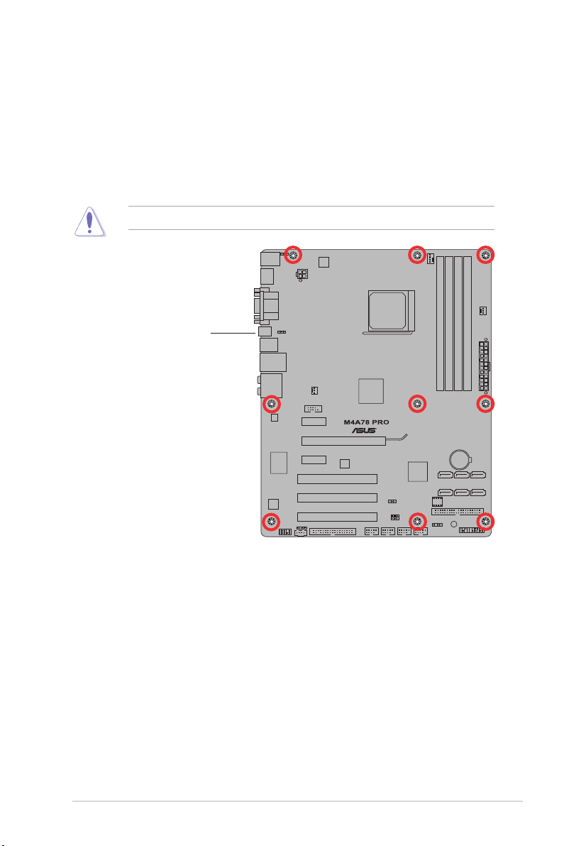
1.5.2 Screw holes
Place nine (9) screws into the holes indicated by circles to secure the motherboard to the
chassis.
Do not overtighten the screws! Doing so can damage the motherboard.
Place this side towards
the rear of the chassis.
Chapter 1: Product introduction 1-5
Page 18
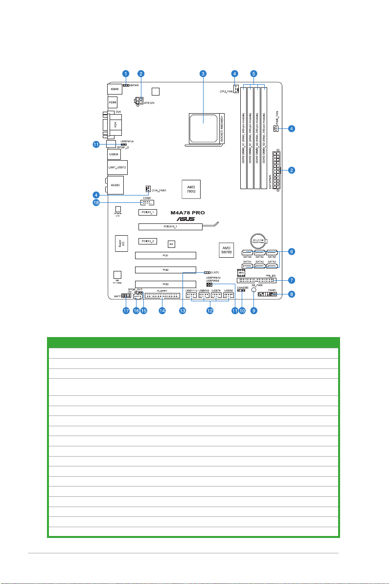
1.5.3 Motherboard layout
1.5.4 Layout contents
Connectors/Jumpers/Slots Page
1. Keyboard power (3-pin KBPWR) 1-18
2. ATX power connectors (24-pin EATXPWR, 4-pin ATX12V) 1-23
3. CPU socket AM2+/AM2 1-7
4. CPU, Chassis and Power Fan connectors (4-pin CPU_FAN, 3-pin CHA_FAN1, 3-pin
PWR_FAN)
5. DDR2 DIMM slots 1-10
6. Serial ATA connectors (7-pin SATA1-6) 1-25
7. IDE connector (40-1 pin PRI_IDE) 1-24
8. System panel connector (10-1 pin PANEL) 1-26
9. Onboard LED (SB_PWR) 1-4
10. Chassis intrusion connector (4-1 pin CHASSIS) 1-22
11. USB device wake-up (3-pin USBPW1-4, USBPW5-8, USBPW9-12) 1-18
12. USB connectors (10-1 pin USB56, USB78, USB910, USB1112) 1-27
13. Clear RTC RAM (CLRTC) 1-17
14. Floppy disk drive connector (34-1 pin FLOPPY) 1-27
15. Digital audio connector (4-1 pin SPDIF_OUT) 1-28
16. Optical drive audio in connector (4-pin CD) 1-28
17. Front panel audio connector (10-1 pin AAFP) 1-29
18. Serial port connector (10-1 pin COM1) 1-29
1-22
1-6 ASUS M4A78 PRO
Page 19
1.6 Central Processing Unit (CPU)
The motherboard comes with a CPU socket designed for AMD® AM3 Phenom™ II /
Athlon™ X4 / Athlon™ X3 / Athlon™ X2 processors and AM2+ / AM2 Phenom™ X4 /
Phenom™ X3 / Athlon™ X2 / Athlon™ / Sempron™ processors.
The CPU socket is not compatible with AMD® Opteron™ processors. Do not install an
Opteron™ processor on this motherboard.
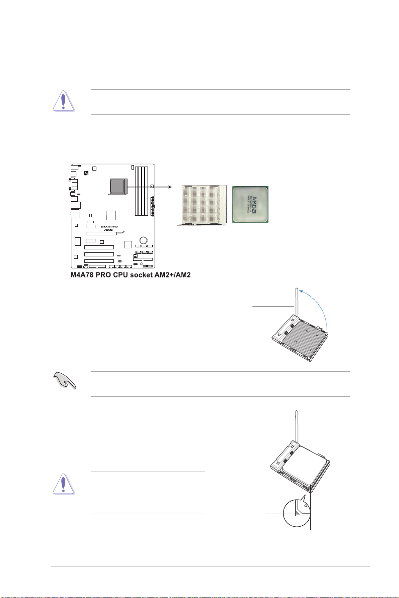
1.6.1 Installing the CPU
To install a CPU:
1. Locate the CPU socket on the motherboard.
2. Press the lever sideways to unlock
the socket, then lift it up to a 90°100° angle.
Socket lever
Ensure that the socket lever is lifted up to 90°-100° angle, otherwise the CPU will not t in
completely.
3. Position the CPU above the socket such that the CPU
corner with the gold triangle matches the socket corner
with a small triangle.
4. Carefully insert the CPU into the socket until it ts in place.
The CPU ts only in one correct
orientation. DO NOT force the CPU into
the socket to prevent bending the pins
and damaging the CPU!
Chapter 1: Product introduction 1-7
Small triangle
Gold triangle
Page 20
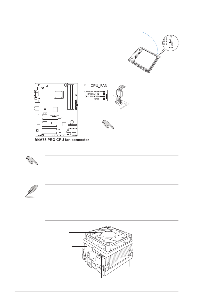
5. When the CPU is in place, push down the socket
lever to secure the CPU. The lever clicks on the side
tab to indicate that it is locked.
6. Install a CPU heatsink and fan following the
instructions that came with the heatsink package.
You can also refer to section 1.6.2 Installing
heatsink and fan for instructions.
7. Connect the CPU fan cable to the CPU_FAN
connector on the motherboard.
Do not forget to connect the CPU
fan connector! Hardware monitoring
errors can occur if you fail to plug this
connector.
1.6.2 Installing the heatsink and fan
Ensure that you use only AMD-certied heatsink and fan assembly.
To install the CPU heatsink and fan:
1. Place the heatsink on top of the installed CPU, making sure that the heatsink ts
properly on the retention module base.
• The retention module base is already installed on the motherboard upon purchase.
• You do not have to remove the retention module base when installing the CPU or
installing other motherboard components.
• If you purchased a separate CPU heatsink and fan assembly, ensure that a Thermal
Interface Material is properly applied to the CPU heatsink or CPU before you install the
heatsink and fan assembly.
CPU Fan
CPU Heatsink
Retention bracket
Retention Module Base
Retention bracket lock
1-8 ASUS M4A78 PRO
Page 21
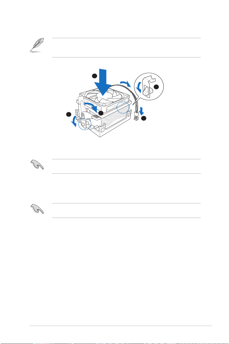
Your boxed CPU heatsink and fan assembly should come with installation instructions for
1
3
4
5
2
the CPU, heatsink, and the retention mechanism. If the instructions in this section do not
match the CPU documentation, follow the latter.
2. Attach one end of the retention bracket to the retention module base.
3. Align the other end of the retention bracket to the retention module base. A clicking
sound denotes that the retention bracket is in place.
Ensure that the fan and heatsink assembly perfectly ts the retention mechanism module
base, otherwise you cannot snap the retention bracket in place.
4. Push down the retention bracket lock on the retention mechanism to secure the
heatsink and fan to the module base.
5. When the fan and heatsink assembly is in place, connect the CPU fan cable to the
connector on the motherboard labeled CPU_FAN.
Do not forget to connect the CPU fan connector! Hardware monitoring errors can occur if
you fail to plug this connector.
Chapter 1: Product introduction 1-9
Page 22

1.7 System memory
1.7.1 Overview
The motherboard comes with two Double Data Rate 2 (DDR2) Dual Inline Memory Modules
(DIMM) sockets. A DDR2 module has the same physical dimensions as a DDR DIMM but
has a 240-pin footprint compared to the 184-pin DDR DIMM. DDR2 DIMMs are notched
differently to prevent installation on a DDR DIMM socket. The gure illustrates the location of
the DDR2 DIMM sockets:
Channel Sockets
Channel A DIMM_A1 and DIMM_A2
Channel B DIMM_B1 and DIMM_B2
1.7.2 Memory congurations
You may install 512MB, 1GB, 2GB and 4GB unbuffered ECC/non-ECC DDR2 DIMMs into the
DIMM sockets.
• You may install varying memory sizes in Channel A and Channel B. The system maps
the total size of the lower-sized channel for the dual-channel conguration. Any excess
memory from the higher-sized channel is then mapped for single-channel operation.
• Always install DIMMs with the same CAS latency. For optimum compatibility, we
recommend that you obtain memory modules from the same vendor.
• Due to the memory address limitation on 32-bit Windows OS, when you install 4GB
or more memory on the motherboard, the actual usable memory for the OS can be
about 3GB or less. For effective use of memory, we recommend that you install a 64-bit
Windows OS when having 4GB or more memory installed on the motherboard.
• This motherboard does not support DIMMs made up of 256 megabit (Mb) chips or less.
• The default memory operation frequency is dependent on its SPD. Under the default
state, some memory modules for overclocking may operate at a lower frequency than
the vendor-marked value.
• For system stability, use a more efcient memory cooling system to support a full
memory load (4 DIMMs) or overclocking condition.
1-10 ASUS M4A78 PRO
Page 23

M4A78 PRO Motherboard Qualied Vendors Lists (QVL)
DDR2-1066MHz capability
DIMM socket support
Vendor Part No. Size
A-DATA Heat-Sink Package 2GB (kit of 2) SS AD21066E001GU 5-5-5-15 N/A •
A-DATA Heat-Sink Package 4GB (kit of 2) DS AD21066E002GU 5-5-5-15 N/A •
Apacer 78.0AG9S.9K4 2GB (kit of 2) DS Heat-Sink Package 5-5-5-15 NA • •
Apacer 78.AAGAL.9KZ 4GB (kit of 2) DS Heat-Sink Package 5-5-5-15 NA • •
G.SKILL F2-8500CL5D-2GBPK 2GB (kit of 2) DS Heat-Sink Package 5-5-5-15 N/A • • •
G.SKILL F2-8500CL5D-4GBPK 4GB (kit of 2) DS Heat-Sink Package 5-5-5-15 N/A •
G.SKILL F2-8500CL5S-1GBPK 2GB DS Heat-Sink Package 5-5-5-15 G.SKILL • • •
GEIL GB24GB8500C5QC 2GB SS GL2L128M88BA25AB 5 GEIL • • •
GEIL GE22GB1066C5DC 2GB SS Heat-Sink Package 5 GEIL • •
GEIL GE24GB1066C5QC 2GB DS Heat-Sink Package 5 GEIL • •
GEIL GX24GB8500C5UDC 4GB (kit of 2) DS Heat-Sink Package 5 N/A • •
Kingmax KLED48F-A8K15 2GB DS KKA8FFIXF-JFS-18A N/A Kingmax • • •
Kingston KHX8500D2/ 512 512MB SS Heat-Sink Package N/A Kingston • • •
Kingston KHX8500D2K2/1GN 512MB SS Heat-Sink Package N/A Kingston • • •
Kingston Heat-Sink Package 2GB DS KHX8500AD2/2G 7-7-7-20 N/A •
Kingston KHX8500D2K2/2GN 2GB DS Heat-Sink Package N/A Kingston •
OCZ OCZ2N1066SR2DK 2GB (kit of 2) DS
Qimonda HYS64T128000EU-1.9-C2 2GB DS
Transcend TX1066QLU-2GK 2GB (kit of 2) SS Heat-Sink Package 5 Transced • •
Transcend TX1066QLJ-2GK 2GB DS Heat-Sink Package 5 Transced • •
Transcend TX1066QLU-4GK 4GB (kit of 2) DS Heat-Sink Package 5 Transced • •
SS/
Chip No. CL
DS
Heat-Sink
Package(EPP)
HYB18T1G800C2F-
1.9FSS25253
Chip
Brand
5-5-5-15 OCZ •
N/A Qimonda •
(Optional)
A* B* C*
Due to AM2+ CPU limitation, only one DDR2 1066 DIMM is supported per channel.When
four DDR2 1066 DIMMs are installed, all DIMMs run at 800Mhz frequency by default for
system stability.
DDR2-800MHz capability
DIMM socket
Vendor Part No. Size
A-Data AD2800E001GOU 2GB (kit of 2) SS Heat-Sink Package
A-Data M2OAD6G3H3160Q1E58 512MB SS AD29608A8A-25EG80812 N/A ADATA • • •
A-Data AD2800E002GOU 4GB (kit of 2) DS Heat-Sink Package
A-Data M2OAD6G314170Q1E58 1GB DS AD29608A8A-25EG80810 N/A ADATA • • •
Apacer 78.01GA0.9K5 1GB SS AM4B5808CQJS8E0749D 5 Apacer • •
SS/
Chip No. CL
DS
4-4-
4-12
4-4-
4-12
Chapter 1: Product introduction 1-11
support (Optional)
Chip
Brand
A* B* C*
N/A • • •
N/A • • •
Page 24

DDR2-800MHz capability (continued)
DIMM socket
Vendor Part No. Size
Apacer 78.A1GA0.9K4 2GB DS AM4B5808CQJS8E0740E 5 Apacer • • •
Corsair CM2X2048-6400C5 4GB (kit of 2) DS Heat-Sink Package 5 Corsair • • •
Corsair XMS2-6400 1GB DS Heat-Sink Package 4 Corsair • • •
Crucial BL12864AA804.8FE5
Crucial BL12864AL804.8FE5
Elixir
Elixir M2Y1G64TU8HB0B-25C 1GB DS
Elixir
G.SKILL F2-6400CL5D-1GBNQ 1GB (kit of 2) SS Heat-Sink Package
G.SKILL F2-6400CL4D-2GBPK 1GB DS Heat-Sink Package 4 G.SKILL • • •
G.SKILL F2-6400CL4D-4GBPK 2GB DS Heat-Sink Package 4 G.SKILL • • •
G.SKILL F2-6400CL5D-2GBNQ 1GB DS Heat-Sink Package 5 G.SKILL • • •
G.SKILL F2-6400CL5D-4GBPQ 2GB DS Heat-Sink Package 5 G.SKILL • • •
G.SKILL F2-6400CL5Q-16GNQ 4GB DS Heat-Sink Package 5 G.SKILL • • •
GEIL GB22GB6400C4DC 1GB DS GL2L64M088BA30EB 4 GEIL • • •
GEIL GB22GB6400C5DC 1GB DS GL2L64M088BA30EB 5 GEIL • • •
GEIL GB24GB6400C4QC 1GB DS GL2L64M088BA30EB 4 GEIL • • •
GEIL GB24GB6400C5DC 2GB DS GL2L128M88BA25AB 5 GEIL • • •
GEIL GB24GB6400C5QC 1GB DS GL2L64M088BA30EB 5 GEIL • • •
GEIL GB28GB6400C4QC 2GB DS GL2L128M88BA25AB 4 GEIL • • •
GEIL GB28GB6400C5QC 2GB DS GL2L128M88BA25AB 5 GEIL • • •
GEIL GE22GB800C4DC 1GB DS Heat-Sink Package 4 GEIL • • •
GEIL GE22GB800C5DC 1GB DS Heat-Sink Package 5 GEIL • • •
GEIL GE24GB800C4DC 2GB DS Heat-Sink Package 4 GEIL • • •
GEIL GE24GB800C4QC 1GB DS Heat-Sink Package 4 GEIL • • •
GEIL GE24GB800C5DC 2GB DS Heat-Sink Package 5 GEIL • • •
GEIL GE24GB800C5QC 1GB DS Heat-Sink Package 5 GEIL • •
GEIL GE28GB800C4QC 2GB DS Heat-Sink Package 4 GEIL • • •
GEIL GE28GB800C5QC 2GB DS Heat-Sink Package 5 GEIL • • •
GEIL GX22GB6400DC 1GB DS Heat-Sink Package 5 GEIL • • •
GEIL GX24GB6400DC 2GB DS Heat-Sink Package 5 GEIL • • •
HY HYMP564U64CP8-S5 AB 512MB SS HY5PS12821CFP-S5 5 Hynix • • •
HY HYMP 512U64CP8-S5 AB 1GB DS HY5PS12821CFPS5 5 Hynix • • •
Kingmax KLDD48F-B8KB5 1GB SS KKB8FFBGXF-CFA-25U N/A Kingmax • • •
Kingmax KLDE88F-B8KB5 2GB DS KKB8FFBGXF-CFA-25U N/A Kingmax • • •
M2Y1G64TU88D5B-AC
0828.GS
M2Y2G64TU8HD5B-AC
0826.SG
2GB (kit of 2)
(EPP)
2GB (kit of 2)
(EPP)
1GB SS N2TU16800E-AC N/A Elixir • • •
2GB DS N2TUG80DE-AC N/A Elixir • •
SS/
Chip No. CL
DS
SS Heat-Sink Package N/A N/A • • •
SS Heat-Sink Package 4 N/A • • •
N2TU 51280BE25C802006Z1DV
5 Elixir • • •
5-55-15
support (Optional)
Chip
Brand
A* B* C*
G.SKILL • • •
1-12 ASUS M4A78 PRO
Page 25

DDR2-800MHz capability (continued)
DIMM socket
Vendor Part No. Size
Kingston KHX6400D2LLK2/1GN 512MB SS Heat-Sink Package N/A Kingston • • •
Kingston KVR800D2N5/ 512 512MB SS E5108AJBG-8E-E 0803A9082 N/A Kingston • • •
Kingston KVR800D2N6/ 512 512MB SS E5108AJBG-8E-E N/A Elpida •
Kingston KHX6400D2/2G 2GB DS Heat-Sink Package N/A Kingston • • •
Kingston KHX6400D2K2/2G 2GB (kit of 2) DS Heat-Sink Package N/A Kingston •
Kingston KHX6400D2LL/1G 1GB DS Heat-Sink Package N/A Kingston • • •
kingston KVR800D2N5/1G 1GB DS
Kingston KVR800D2N5/2G 2GB DS E1108ACBG-8E-E N/A Elpida • • •
Kingston KVR800D2N6/2G 2GB DS 461625.010819 PTGC N/A Kingston • • •
Micron MT9HTF12872AY-800E1 1GB SS D9HNP 7YE22(ECC) 6 Micron • • •
Micron MT9HTF6472AY-80ED4 512MB SS 6ED22D9GKX(ECC) 5 Micron • • •
Micron MT18HTF12872AY-80ED4 1GB DS 6TD22D9GKX(ECC) 5 Micron • •
OCZ OCZ2G800R22GK 1GB DS Heat-Sink Package 5 OCZ • • •
OCZ OCZ2P8004GK 2GB DS Heat-Sink Package 5 OCZ • • •
OCZ OCZ2P800R22GK 1GB DS Heat-Sink Package 4 OCZ • • •
OCZ OCZ2RPR8002GK 1GB DS Heat-Sink Package 4 OCZ • • •
OCZ OCZ2VU8004GK 1GB DS Heat-Sink Package 6 OCZ • •
PSC AL7E8E63H-10E1K 2GB DS A3R1GE3CFF750RABBP(ECC) 5 PSC • • •
PSC AL8E8F73C-8E1 2GB DS A3R1GE3CFF734MAA0E 5 PSC • • •
PSC PL8E8F73C-8E1 2GB DS SHG772-AA3G N/A psc • • •
PSC PL8E8G73E-8E1 2GB DS XCP271A3G-A N/A psc • • •
Samsung M378T2863QZS-CF7 1GB SS K4T1G084QQ-HCF7 6 Samsung • • •
Samsung M378T6553GZS-CF7 512MB SS K4T51083QG-HCF7 6 Samsung • • •
Samsung M391T2863QZ3-CF7 1GB SS K4T1G084QQ-HCF7(ECC) 6 Samsung • • •
Samsung M378T5263AZ3-CF7 4GB DS K4T2G084QA-HCF7 N/A Samsung • • •
Transcend JM800QLU-1G 1GB SS TQ1243PCF8 5 Transcend • • •
Transcend TS128MLQ64V8U 1GB SS E1108ACBG-8E-E 5 Elpaid • • •
Transcend TS64MLQ64V8J 512MB SS 7HD22 D9GMH 5 Micron • • •
Transcend JM800QLJ-1G 1GB DS TQ123PJF8F0801 5 Transcend • • •
Transcend JM800QLU-2G 2GB DS TQ243PCF8 5 Transcend • •
Transcend TS128MLQ64V8J 1GB DS 7HD22D9GMH 5 Mircon • • •
Transcend TS256MLQ64V8U 2GB DS E1108ACBG-8E-E 5 Elpida • • •
Transcend TS256MLQ72V8U 2GB DS E1108ACBG-8E-E(ECC) N/A Elpida • • •
VDATA M2GVD6G3H3160Q1E52 512MB SS VD29608A8A-25EG20813 N/A VDATA • • •
Samsung M391T5663QZ3-CF7 2GB DS K4T1G084QQ-HCF7(ECC) 6 Samsung • • •
SS/
Chip No. CL
DS
D6408TR4CGL25USL3624
06PECXA
N/A kingston • • •
Chip
Brand
support (Optional)
A* B* C*
Chapter 1: Product introduction 1-13
Page 26

DDR2-667MHz capability
DIMM socket
Vendor Part No. Size
ADATA M2OAD5G314170Q1C58 1GB DS AD29608A8A-3EG80814 N/A ADATA • • •
ADATA M2OAD5H3J4170I1C53 2GB DS AD20908A8A-3EG 30724 N/A ADATA • • •
Apacer 78.01G9O.9K5 1GB SS AM4B5808CQJS7E0751C 5 Apacer • • •
Apacer 78.91G92.9K5 512MB SS AM4B5708JQJS7E0751C 5 Apacer • • •
Apacer AU 512E667C5KBGC 512MB SS AM4B5708GQJS7E06332F 5 Apacer •
Apacer 78.A1G9O.9K4 2GB DS AM4B5808CQJS7E0749B 5 Apacer • • •
Apacer AU01GE667C5KBGC 1GB DS AM4B5708GQJS7E0636B N/A Apacer • • •
Corsair XMS2-5400 1GB DS Heat-Sink Package 4 Corsair • • •
G.SKILL F2-5300CL5D-4GBMQ 4GB (kit of 2) DS Heat-Sink Package
G.SKILL F2-5400PHU2-2GBNT 2GB (kit of 2) DS D2 64M8CCF 0815 C7173S
GEIL GX22GB5300LX 2GB DS Heat-Sink Package 5 GEIL • • •
GEIL GX24GB5300LDC 2GB DS Heat-Sink Package 5 GEIL • • •
Kingmax KLCC28F-A8KB5 512MB SS KKEA88B4LAUG-29DX N/A Kingmax • • •
Kingmax KLCD48F-A8KB5 1GB DS KKEA88B4LAUG-29DX N/A Kingmax • • •
Kingston KVR667D2N5/ 512 512MB SS
Kingston KVR667D2N5/1G 1GB DS
Kingston KVR667D2N5/2G 2GB DS 7RE22 D9HNL N/A Micron • • •
Kingston KVR667D2N5/2G 2GB DS E1108ACBG-8E-E 0813A90CC N/A Elpida • • •
Nanya NT 512T64U88A1BY-3C 512MB SS NT5TU64M8AE-3C N/A Nanya • • •
Nanya NT1GT64U8HB0BY-3C 1GB DS NT5TU64M8BE-3C72155700CP 5 Nanya • • •
PSC AL6E8E63J-6E1 512MB SS A3R12E3JFF717B9A00 5 PSC • • •
PSC AL7E8F73C-6E1 1GB SS A3R1GE3CFF734MAA0J 5 PSC • • •
PSC AL7E8E63J-6E1 1GB DS A3R12E3JFF717B9A01 5 PSC • • •
Qimonda HYS64T64000EU-3S-B2 512MB SS
Qimonda HYS64T128020EU-3S-B2 1GB DS
Samsung M378T5263AZ3-CE6 4GB DS K4T2G084QA-HCE6 N/A Samsung • • •
Super Talent T667UB1GV 1GB DS PG 64M8-800 0750 5
Transcend JM667QLJ-1G 1GB DS E5108AJBG-6E-E 5 Elpida • • •
Twinmos 8D-A3JK5MPETP 512MB SS A3R12E3GEF633ACAOY 5 PSC • • •
ELIXIR M2Y1G64TU8HA2B-3C 1GB DS M2TU 51280AE-3C717095R28F 5 ELIXIR • •
ELIXIR M2Y1G64TU8HBOB-3C 1GB DS
Leadmax LRMP 512U64A8-Y5 1GB DS HY5PS12821CFP-Y5 C 702AA N/A Hynix • • •
Kingston KVR667D2E5/1G 1GB DS E5108AJBG-8E-E(ECC) 5 Elpida • • •
Kingston KVR667D2E5/2G 2GB DS NT5TU128M8DE-3C(ECC) 5 Elpida • • •
SS/
Chip No. CL
DS
SO1237650821 SBP D6408TR4
CGL25USL074905PECNB
SO1280420822 SOP D6408TR4
CGL25USL156304PECXA
HYB18T
512B00B2F3SFSS28171
HYB18T
512B00B2F3SFSS28171
N2TU 51280BE3C639009W1CF
5-55-15
5-55-15
N/A Kingston • • •
N/A Kingston • • •
5 Qimonda • • •
5 Qimonda • • •
5 ELIXIR • • •
support (Optional)
Chip
Brand
A* B* C*
G.SKILL • • •
G.SKILL • • •
Super
• • •
Talent
1-14 ASUS M4A78 PRO
Page 27

Side(s): SS - Single-sided DS - Double-sided
DIMM support:
• A*: Supports one module inserted into either slot as Single-channel memory
conguration.
• B*: Supports two modules inserted into either the yellow slots or the black slots as one
pair of Dual-channel memory conguration.
• C*: Supports four modules inserted into both the yellow slots and the black slots as two
pairs of Dual-channel memory conguration.
Visit the ASUS website for the latest QVL.
1.7.3 Installing a DIMM
Unplug the power supply before adding or removing DIMMs or other system components.
Failure to do so can cause severe damage to both the motherboard and the components.
1. Press the retaining clips outward to
unlock a DDR2 DIMM socket.
2. Align a DIMM on the socket such that
the notch on the DIMM matches the
break on the socket.
Unlocked retaining clip
A DDR2 DIMM is keyed with a notch so that it ts in only one direction. DO NOT force a
DIMM into a socket to avoid damaging the DIMM.
3. Firmly insert the DIMM into the socket
until the retaining clips snap back in
place and the DIMM is properly seated.
2
DDR2 DIMM notch
1
1
3
Locked Retaining Clip
1.7.4 Removing a DIMM
To remove a DIMM:
1. Simultaneously press the retaining clips
outward to unlock the DIMM.
Support the DIMM lightly with your
ngers when pressing the retaining
clips. The DIMM might get damaged
when it ips out with extra force.
1
2. Remove the DIMM from the socket.
Chapter 1: Product introduction 1-15
2
DDR2 DIMM notch
1
Page 28

1.8 Expansion slots
In the future, you may need to install expansion cards. The following sub-sections describe
the slots and the expansion cards that they support.
Unplug the power cord before adding or removing expansion cards. Failure to do so may
cause you physical injury and damage motherboard components.
1.8.1 Installing an expansion card
To install an expansion card:
1. Before installing the expansion card, read the documentation that came with it and
make the necessary hardware settings for the card.
2. Remove the system unit cover (if your motherboard is already installed in a chassis).
3. Remove the bracket opposite the slot that you intend to use. Keep the screw for later
use.
4. Align the card connector with the slot and press rmly until the card is completely
seated on the slot.
5. Secure the card to the chassis with the screw you removed earlier.
6. Replace the system cover.
1.8.2 Conguring an expansion card
After installing the expansion card, congure it by adjusting the software settings.
1. Turn on the system and change the necessary BIOS settings, if any. See Chapter 2 for
information on BIOS setup.
2. Assign an IRQ to the card.
3. Install the software drivers for the expansion card.
When using PCI cards on shared slots, ensure that the drivers support “Share IRQ” or that
the cards do not need IRQ assignments. Otherwise, conicts will arise between the two PCI
groups, making the system unstable and the card inoperable. Refer to the table on the next
page for details.
1.8.3 PCI slots
The PCI slots support cards such as a LAN card, SCSI card, USB card, and other cards that
comply with PCI specications.
1.8.4 PCI Express x1 slots
This motherboard supports PCI Express x1 network cards, SCSI cards, and other cards that
comply with the PCI Express specications.
1.8.5 PCI Express x16 slot
This motherboard supports a PCI Express x16 graphics card that complies with the PCI
Express specications.
1-16 ASUS M4A78 PRO
Page 29

1.9 Jumpers
1. Clear RTC RAM (CLRTC)
This jumper allows you to clear the Real Time Clock (RTC) RAM in CMOS. You can
clear the CMOS memory of date, time, and system setup parameters by erasing
the CMOS RTC RAM data. The onboard button cell battery powers the RAM data in
CMOS, which include system setup information such as system passwords.
To erase the RTC RAM
1. Turn OFF the computer and unplug the power cord.
2. Move the jumper cap from pins 1-2 (default) to pins 2-3. Keep the cap on pins 2-3
for about 5~10 seconds, then move the cap back to pins 1-2.
3. Plug the power cord and turn ON the computer.
4. Hold down the <Del> key during the boot process and enter BIOS setup to re-enter
data.
Except when clearing the RTC RAM, never remove the cap on CLRTC jumper default
position. Removing the cap will cause system boot failure!
• If the steps above do not help, remove the onboard battery and move the jumper again
to clear the CMOS RTC RAM data. After the CMOS clearance, reinstall the battery.
• You do not need to clear the RTC when the system hangs due to overclocking. For
system failure due to overclocking, use the C.P.R. (CPU Parameter Recall) feature. Shut
down and reboot the system so the BIOS can automatically reset parameter settings to
default values.
• Due to the chipset behavior, AC power off is required to enable C.P.R. function. You
must turn off and on the power supply or unplug and plug the power cord before
rebooting the system.
Chapter 1: Product introduction 1-17
Page 30

2. Keyboard power (3-pin KBPWR)
This jumper allows you to enable or disable the keyboard wake-up feature. Set
this jumper to pins 2-3 (+5VSB) to wake up the computer by pressing a key on the
keyboard (the default is the Space Bar). This feature requires an ATX power supply
that can supply at least 1A on the +5VSB lead, and a corresponding setting in the
BIOS.
3. USB device wake-up (3-pin USBPW1-4, USBPW5-8, USBPW9-12)
Set these jumpers to +5V to wake up the computer from S1 sleep mode (CPU
stopped, DRAM refreshed, system running in low power mode) using the connected
USB devices. Set to +5VSB to wake up from S3 and S4 sleep modes (no power to
CPU, DRAM in slow refresh, power supply in reduced power mode). The USBPW1-4
jumpers are for the rear USB ports. The USBPW5-8 and USBPW9-12 jumpers are for
the internal USB connectors that you connect to additional USB ports.
1-18 ASUS M4A78 PRO
Page 31

1.10 Connectors
1.10.1 Rear panel connectors
1. PS/2 mouse port. This port is for a PS/2 mouse.
2. Video Graphics Adapter (VGA) port This 15-pin port is for a VGA monitor or other
VGA-compatible devices.
3. LAN (RJ-45) port. This port allows Gigabit connection to a Local Area Network (LAN)
through a network hub.
LAN port LED indications
Activity LED Speed LED
Status Description Status Description
OFF No link OFF 10 Mbps connection
OFF Linked ORANGE 100 Mbps connection
BLINKING Data activity GREEN 1 Gbps connection
4. PS/2 keyboard port. This port is for a PS/2 keyboard.
5. HDMI Out port. This port is for a high-denition multimedia interface (HDMI) connector.
6. DVI-I Out port. This port is for any DVI-I compatible device and are HDCP compliant,
allowing playback of HD DVD, Blu-Ray and other protected content.
7. Optical S/PDIF Out port. This port connects an external audio output device via an
optical S/PDIF cable.
8. USB 2.0 ports 3 and 4. These two 4-pin Universal Serial Bus (USB) ports are
available for connecting USB 2.0 devices.
9. USB 2.0 ports 1 and 2. These two 4-pin Universal Serial Bus (USB) ports are
available for connecting USB 2.0 devices.
10. 8-channel audio ports. These ports connects to a multi-speaker audio system.
Audio 2, 4, 6-channel conguration
Port
Light Blue Line In Line In Line In Line In
Lime Line Out Front Speaker Out Front Speaker Out Front Speaker Out
Pink Mic In Mic In Mic In Mic In
Orange – – Center/Subwoofer Center/Subwoofer
Black – Rear Speaker Out Rear Speaker Ou Rear Speaker Out
Gray – – – Side Speaker Out
Headset
2-channel
4-channel 6-channel 8-channel
SPEED LEDACT LED
LAN port
Chapter 1: Product introduction 1-19
Page 32

Dual display table
This table indicates whether the dual display you want to use is supported or not.
Dual display output Support Not support
DVI + D-Sub •
HDMI + D-Sub •
DVI + HDMI •
Playback of HD DVD and Blu-Ray Discs
For better playback quality, we suggest that you follow the system requirements in the
suggested list below.
Suggested list
CPU AMD® Athlon 4400+
DIMM DDR2 800 (1GB or higher)
BIOS setup Frame Buffer Size--256MB or higher
Playback
software
CyberLink® PowerDVD 7.3
(not supporting video acceleration)
File format
Non-protected clips 1920 x 1080p 1920 x 1080p
HD-DVD 1920 x 1080p 1280 x 1080p
Blu-Ray 1280 x 1080p 1280 x 1080p
Windows XP Windows Vista
Best resolution
1-20 ASUS M4A78 PRO
Page 33

Troubleshooting on HDTV overscaling or underscaling:
If your desktop is extending beyond the viewable display area or the desktop or image is not
lling the entire display area while using the onboard HDMI out port and the HDMI cable, you
can resize the desktop appearing on your HDTV screen.
To resize your HDTV desktop:
1. Install AMD Chipset Driver from the motherboard support DVD.
2. Right-click the desktop and select ATI CATALYST(R) Control Center.
3. From the Graphics Settings tree, expand DTV (HDMI™) 1.
4. Click Scaling Options.
5. Move the Underscan/Overscan slider to adjust the overall size of the display on the
HDMI™ DTV.
Using this slider increases or decreases any black borders that may be visible around
the outside of the display.
3
4
5
6
6. To ensure that forcing a custom display mode through the ATI Displays Manager does
not create conicting resolutions, select the Use the scaling values instead of the
customized settings when the desktop resolution does not match your DFP
resolution check box.
The Scaling Options function of the DTV (HDMI™) 1 item in the ATI CATALYST Control
Center is adjustable only when you are using an HDTV compliance resolution such as 480i,
720i, or 1080i.
Chapter 1: Product introduction 1-21
Page 34

1.10.2 Internal connectors
1. CPU, Chassis and Power Fan connectors (4-pin CPU_FAN, 3-pin CHA_FAN1,
3-pin PWR_FAN)
The fan connectors support cooling fans of 350mA~740mA (8.88W max.) or a total of
1A~2.22A (26.64W max.) at +12V. Connect the fan cables to the fan connectors on the
motherboard, making sure that the black wire of each cable matches the ground pin of
the connector.
Do not forget to connect the fan cables to the fan connectors. Insufcient air ow inside the
system may damage the motherboard components. These are not jumpers! DO NOT place
jumper caps on the fan connectors.
Only the CPU_FAN and CHA_FAN1 connectors support the ASUS Q FAN 2 feature.
2. Chassis intrusion connector (4-1 pin CHASSIS)
This connector is for a chassis-mounted intrusion detection sensor or switch. Connect
one end of the chassis intrusion sensor or switch cable to this connector. The chassis
intrusion sensor or switch sends a high-level signal to this connector when a chassis
component is removed or replaced. The signal is then generated as a chassis intrusion
event.
By default, the pins labeled “Chassis Signal” and “Ground” are shorted with a jumper
cap. Remove the jumper caps only when you intend to use the chassis intrusion
detection feature.
1-22 ASUS M4A78 PRO
Page 35

3. ATX power connectors (24-pin EATXPWR, 4-pin ATX12V)
These connectors are for an ATX power supply. The plugs from the power supply are
designed to t these connectors in only one orientation. Find the proper orientation and
push down rmly until the connectors completely t.
•
We recommend that you use an ATX 12 V Specication 2.0-compliant power supply
unit (PSU) with a minimum of 300 W power rating. This PSU type has 24-pin and 4-pin
power plugs.
•
If you intend to use a PSU with 20-pin and 4-pin power plugs, ensure that the 20-pin
power plug can provide at least 15 A on +12 V and that the PSU has a minimum power
rating of 300 W. The system may become unstable or may not boot up if the power is
inadequate.
•
Do not forget to connect the 4-pin ATX +12 V power plug. Otherwise, the system will not
boot up.
• We recommend that you use a PSU with higher power output when conguring a
system with more power-consuming devices or when you intend to install additional
devices. The system may become unstable or may not boot up if the power is
inadequate.
•
If you are uncertain about the minimum power supply requirement for your system,
refer to the Recommended Power Supply Wattage Calculator at http://support.asus.
com/PowerSupplyCalculator/PSCalculator.aspx?SLanguage=en-us for details.
Chapter 1: Product introduction 1-23
Page 36

4. IDE connector (40-1 pin PRI_IDE)
The onboard IDE connector is for Ultra DMA 133/100/66 signal cable. There are
three connectors on each Ultra DMA 133 / 100 / 66 signal cable: blue, black, and gray.
Connect the blue connector to the motherboard’s IDE connector, then select one of the
following modes to congure your devices:
Drive jumper setting Mode of device(s) Cable connector
Single device Cable-Select or Master - Black
Cable-Select
Two devices
Master Master
Slave Slave
• Pin 20 on the IDE connector is removed to match the covered hole on the Ultra DMA
cable connector. This prevents incorrect insertion when you connect the IDE cable.
• Use the 80-conductor IDE cable for Ultra DMA 133/100/66 IDE devices.
Master Black
Slave Gray
Black or gray
If any device jumper is set as “Cable-Select”, ensure that all other device jumpers have the
same setting.
1-24 ASUS M4A78 PRO
Page 37

5. Serial ATA connectors (7-pin SATA1-6)
These connectors are for the Serial ATA signal cables for Serial ATA 3Gb/s hard disk
and optical disk drives. The Serial ATA 3Gb/s is backward compatible with Serial ATA
1.5Gb/s specication. The data transfer rate of the Serial ATA 3Gb/s is faster than the
standard parallel ATA with 133 MB/s (Ultra DMA133). If you install Serial ATA hard disk
drives, you can create a RAID 0, RAID 1, RAID 10 and JBOD conguration through the
onboard SB700 chipset.
Important note on Serial ATA
Install Windows® XP Service Pack 1 or later version before using Serial ATA.
• For detailed instructions on how to congure RAID 0, RAID 1, RAID 10 and JBOD, refer
to the RAID manual in the support DVD.
• If you intend to create a Serial ATA RAID set using these connectors, set the OnChip
SATA Type item in the BIOS to [RAID]. See page 2-11 for details.
Chapter 1: Product introduction 1-25
Page 38

6. System panel connector (10-1 pin PANEL)
This connector supports several chassis-mounted functions.
• System power LED (2-pin PWRLED)
This 2-pin connector is for the system power LED. Connect the chassis power LED
cable to this connector. The system power LED lights up when you turn on the system
power, and blinks when the system is in sleep mode.
•
Hard disk drive activity LED (2-pin HDLED)
This 2-pin connector is for the HDD Activity LED. Connect the HDD Activity LED cable
to this connector. The IDE LED lights up or ashes when data is read from or written to
the HDD.
•
Power/Soft-off button (2-pin PWRBTN)
This 2-pin connector is for the system power button. Pressing the power button turns
the system ON or puts the system in SLEEP or SOFT-OFF mode depending on the
BIOS settings. Pressing the power switch for more than four seconds while the system
is ON turns the system OFF.
•
Reset button (2-pin RESET)
This 2-pin connector is for the chassis-mounted reset button for system reboot without
turning off the system power.
1-26 ASUS M4A78 PRO
Page 39

7. USB connectors (10-1 pin USB56, USB78, USB910, USB1112)
These connectors are for USB 2.0 ports. Connect the USB module cable to any of
these connectors, then install the module to a slot opening at the back of the system
chassis. These USB connectors comply with USB 2.0 specication that supports up to
480 Mbps connection speed.
Never connect a 1394 cable to the USB connectors. Doing so will damage the
motherboard!
The USB 2.0 module is purchased separately.
8. Floppy disk drive connector (34-1 pin FLOPPY)
This connector is for a Floppy Disk Drive (FDD) signal cable. Insert one end of the
cable to this connector, then connect the other end to the signal connector at the back
of the oppy disk drive.
• Pin 5 on the connector is removed to prevent incorrect cable connection when using an
FDD cable with a covered Pin 5.
• The Floppy Disk Drive signal cable is purchased separately.
Chapter 1: Product introduction 1-27
Page 40

9. Optical drive audio in connector (4-pin CD)
This connector allows you to receive stereo audio input from sound sources such as a
CD-ROM, TV tuner, or MPEG card.
10. Digital audio connector (4-1 pin SPDIF_OUT)
This connector is for an additional Sony/Philips Digital Interface (S/PDIF) ports.
The S/PDIF module is purchased separately.
1-28 ASUS M4A78 PRO
Page 41

11. Front panel audio connector (10-1 pin AAFP)
This connector is for a chassis-mounted front panel audio I/O module that supports
either High Denition Audio or AC`97 audio standard. Connect one end of the front
panel audio I/O module cable to this connector.
• We recommend that you connect a high-denition front panel audio module to this
connector to avail of the motherboard high-denition audio capability.
• If you want to connect a high-denition front panel audio module to this connector,
ensure that the Front Panel Select item in the BIOS is set to [HD]. If you want to
connect an AC’97 front panel audio module to this connector, set the item to [AC97].
See page 2-20 for details.
12. Serial port connector (10-1 pin COM1)
The connector is for a serial (COM) port. Connect the serial port module cable to the
connector, then install the module to a slot opening at the back of the system chassis.
The serial port bracket (COM1) is purchased separately.
Chapter 1: Product introduction 1-29
Page 42

ASUS Q-Connector (system panel)
You can use the ASUS Q-Connector to connect/disconnect chassis front panel cables in a
few steps. Refer to the instructions below to install the ASUS Q-Connector.
1. Connect the front panel cables to the ASUS
Q-Connector.
Refer to the labels on the Q-Connector to
know the detailed pin denitions, then match
them to the respective front panel cable
labels.
The labels of the front panel cables
may differ from chassis made by
different manufacturers.
2. Install the ASUS Q-Connector to the system
panel connector, making sure the orientation
matches the labels on the motherboard.
3. The front panel functions are now enabled.
The gure shows the Q-Connector properly
installed on the motherboard.
1-30 ASUS M4A78 PRO
Page 43

1.11 Software support
1.11.1 Installing an operating system
This motherboard supports Windows® XP/Vista Operating Systems (OS). Always install the
latest OS version and corresponding updates to maximize the features of your hardware.
• Motherboard settings and hardware options vary. Use the setup procedures presented in
this chapter for reference only. Refer to your OS documentation for detailed information.
• Ensure that you install Windows® XP Service Pack 1 or later versions before installing
the drivers for better compatibility and system stability.
1.11.2 Support DVD information
The Support DVD that comes with the motherboard package contains the drivers, software
applications, and utilities that you can install to avail all motherboard features.
• The contents of the Support DVD are subject to change at any time without notice. Visit
the ASUS website at www.asus.com for updates.
• For detailed software instructions, see the Manual menu in the Support DVD or
download the latest software manual from the ASUS website at www.asus.com.
To run the Support DVD
Place the Support DVD to the optical drive. The DVD automatically displays the Drivers menu
if Autorun is enabled in your computer.
The screen on the next page is used for reference only.
Click an icon to
display Support DVD/
motherboard information
Click an item to install
If Autorun is NOT enabled in your computer, browse the contents of the Support DVD to
locate the le ASSETUP.EXE from the BIN folder. Double-click the ASSETUP.EXE to run
the DVD.
Chapter 1: Product introduction 1-31
Page 44

1-32 ASUS M4A78 PRO
Page 45

Chapter 2
BIOS information
2.1 Managing and updating your BIOS
Save a copy of the original motherboard BIOS le to a bootable oppy disk or a USB ash
disk in case you need to restore the BIOS in the future. Copy the original motherboard
BIOS using the ASUS Update or AFUDOS utilities.
2.1.1 Creating a bootable oppy disk
To create a bootable oppy disk
1. Insert a formatted, high density 1.44MB oppy disk to the oppy disk drive.
2. Follow the instructions based on your system environment.
DOS environment
a. At the DOS prompt, type format A:/S then press <Enter>.
Windows® XP environment
a. From the Windows® desktop, click Start > My Computer.
b. Select the 3 1/2 Floppy Drive icon.
c. Click File from the menu, then select Format. A Format 3 1/2 Floppy window
appears.
d. Select Create an MS-DOS startup disk from the format options eld, then click
Start.
Windows® Vista environment
a. From the Windows® desktop, click > Computer.
b. Right-click Floppy Disk Drive then click Format to display the Format 3 1/2
Floppy dialog box.
c. Select the Create an MS-DOS startup disk check box.
d. Click Start.
2. Copy the original or the latest motherboard BIOS le to the bootable oppy disk.
Chapter 2: BIOS setup 2-1
Page 46

2.1.2 ASUS Update utility
The ASUS Update is a utility that allows you to manage, save, and update the motherboard
BIOS in Windows® environment.
• ASUS Update requires an Internet connection either through a network or an Internet
Service Provider (ISP).
• This utility is available in the support DVD that comes with the motherboard package.
Installing ASUS Update
To install ASUS Update:
1. Place the support DVD in the optical drive. The Drivers menu appears.
2. Click the Utilities tab, and then click Install ASUS Update.
3. Follow the onscreen instructions to complete the installation.
Quit all Windows® applications before you update the BIOS using this utility.
Updating the BIOS
To update the BIOS:
1. From the Windows® desktop, click Start > Programs > ASUS > ASUSUpdate >
ASUSUpdate to launch the ASUS Update utility.
2. From the dropdown list, select any of the updating process:
Updating from the Internet
a. Select Update BIOS from the Internet, and then click Next.
b. Select the ASUS FTP site nearest you to avoid network trafc, or click Auto
Select, and then click Next.
c. From the FTP site, select the BIOS version that you wish to download, and then
click Next.
The ASUS Update utility is capable of updating itself through the Internet. Always update
the utility to avail all its features.
Updating from a BIOS file
a. Select Update BIOS from a le, and then click Next.
b. Locate the BIOS le from the Open window, and then click Open.
3. Follow the onscreen instructions to complete the updating process.
2-2 ASUS M4A78 PRO
Page 47

2.1.3 ASUS EZ Flash 2 utility
The ASUS EZ Flash 2 feature allows you to update the BIOS without having to use a
bootable oppy disk or a DOS-based utility.
Download the latest BIOS le from the ASUS website at www.asus.com.
To update the BIOS using EZ Flash 2:
1. Insert the oppy/USB ash disk that contains the latest BIOS le to the oppy disk
drive or the USB port, then launch EZ Flash 2. You can launch EZ Flash 2 in two ways.
a. Press <Alt> + <F2> during POST to display the following:
ASUSTek EZ Flash 2 BIOS ROM Utility V3.34
FLASH TYPE: MXIC 25L8005
Current ROM
BOARD: M4A78 PRO
VER: 0209
DATE: 12/01/2008
PATH: A:\
A:
Note
[Enter] Select or Load [Tab] Switch [V] Drive Info
[Up/Down/Home/End] Move [B] Backup [ESC] Exit
b. Enter the BIOS setup program. Go to the Tools menu to select EZ Flash 2 and
press <Enter> to enable it.
Press <Tab> to switch between drives until the correct BIOS le is found.
4. When the correct BIOS le is found, EZ Flash 2 performs the BIOS update process
and automatically reboots the system when done.
Update ROM
BOARD: Unknown
VER: Unknown
DATE: Unknown
• This function can support devices such as USB ash disk, or oppy disk with FAT 32/16
format and single partition only.
• Do not shut down or reset the system while updating the BIOS to prevent system boot
failure!
Chapter 2: BIOS setup 2-3
Page 48

2.1.4 AFUDOS utility
The AFUDOS utility allows you to update the BIOS le in DOS environment using a bootable
oppy disk. This utility also allows you to copy the current BIOS le that you can use as
backup when the BIOS fails or gets corrupted during the updating process.
• Ensure that you prepare two oppy disks: the bootable oppy disk and the oppy disk
containing the AFUDOS utility and the latest BIOS le.
• Ensure that the oppy disk is not write-protected and has at least 1072KB to save the
AFUDOS and BIOS les.
• The succeeding BIOS screens are for reference only. The actual BIOS screen displays
may not be the same as shown.
Updating the BIOS le
To update the BIOS le using the AFUDOS utility:
1. Insert the bootable oppy disk into the oppy disk drive to boot the system in DOS
mode.
2. Replace the bootable oppy disk and insert the oppy disk that contains the AFUDOS
utility and the latest BIOS le.
• Obtain the AFUDOS utility (afudos.exe) from the bundled support DVD and the latest
BIOS le from the ASUS website at www.asus.com.
• We recommend that you write the BIOS lename on a piece of paper. You will need to
key in the exact BIOS lename at the DOS prompt later.
3. At the DOS prompt, key in afudos /i[lename]
where [lename] is the BIOS le in the oppy disk.
A:\>afudos /iM4A78PRO.ROM
Press <Enter>.
Do not shut down or reset the system while updating the BIOS to prevent system boot
failure!
4. The utility returns to the DOS prompt after the BIOS updating process is completed.
Reboot the system from the hard disk drive.
2-4 ASUS M4A78 PRO
Page 49

2.1.5 ASUS CrashFree BIOS 3 utility
The ASUS CrashFree BIOS 3 is an auto recovery tool that allows you to restore the BIOS le
when it fails or gets corrupted during the updating process. You can update a corrupted BIOS
le using the motherboard support DVD, a oppy disk, or a USB ash disk that contains the
updated BIOS le.
• Prepare the motherboard support DVD, the oppy disk, or the USB ash disk containing
the updated motherboard BIOS before using this utility.
• For the M4A78 PRO motherboard, this utility will not function when you use a PATA
optical drive.
• Always connect the SATA cable to the SATA1 / SATA 2 connector. Otherwise, the utility
will not function.
Recovering the BIOS
To recover the BIOS:
1. Turn on the system.
2. Insert the oppy disk, support DVD, or USB ash disk containing BIOS le to the disk
drive or port.
3. The utility displays the following message and automatically checks the oppy disk,
support DVD, or USB ash disk for the BIOS le.
Bad BIOS checksum. Starting BIOS recovery...
Checking for oppy...
When found, the utility reads the BIOS le and starts erasing the corrupted BIOS le.
Bad BIOS checksum. Starting BIOS recovery...
Checking for oppy...
Floppy found!
Reading le “M4A78PRO.ROM”. Completed.
Start erasing...
4. Restart the system after the utility completes the updating process.
• Only the USB ash disk with FAT 32/16 format and single partition can support ASUS
CrashFree BIOS 3. The device size should be smaller than 8GB.
• DO NOT shut down or reset the system while updating the BIOS! Doing so can cause
system boot failure!
• The utility automatically checks the oppy disk rst. If no oppy disk is found, the utility
then checks the optical drive and the USB ash disk.
• The recovered BIOS may not be the latest BIOS version for this motherboard. Download
the latest BIOS le from the ASUS website at www.asus.com.
Chapter 2: BIOS setup 2-5
Page 50

2.2 BIOS setup program
This motherboard supports a programmable rmware chip that you can update using the
provided utility described in section 2.1 Managing and updating your BIOS.
Use the BIOS Setup program when you are installing a motherboard, reconguring your
system, or prompted to “Run Setup”. This section explains how to congure your system
using this utility.
Even if you are not prompted to use the Setup program, you can change the conguration of
your computer in the future. For example, you can enable the security password feature or
change the power management settings. This requires you to recongure your system using
the BIOS Setup program so that the computer can recognize these changes and record them
in the CMOS RAM of the rmware chip.
The rmware chip on the motherboard stores the Setup utility. When you start up the
computer, the system provides you with the opportunity to run this program. Press <Del>
during the Power-On Self-Test (POST) to enter the Setup utility. Otherwise, POST continues
with its test routines.
If you wish to enter Setup after POST, reboot the system by doing any of the following
procedures:
• Restart using the OS standard shut-down procedure.
• Press <Ctrl>+<Alt>+<Del> simultaneously.
• Press the reset button on the system chassis.
• Press the power button to turn the system off then back on.
Using the power button, reset button, or the <Ctrl>+<Alt>+<Del> keys to force reset from
a running operating system can cause damage to your data or system. We recommend to
always shut-down the system properly from the operating system.
The Setup program is designed to make it as easy to use as possible. Being a menu-driven
program, it lets you scroll through the various submenus and make your selections from the
available options using the navigation keys.
• The default BIOS settings for this motherboard apply for most conditions to ensure
optimum performance. If the system becomes unstable after changing any BIOS
settings, load the default settings to ensure system compatibility and stability. Select the
Load Setups Default item under the Exit Menu. See section 2.9 Exit Menu.
• The BIOS setup screens shown in this section are for reference purposes only, and may
not exactly match what you see on your screen.
• Visit the ASUS website at www.asus.com to download the latest BIOS le for this
motherboard.
2-6 ASUS M4A78 PRO
Page 51

2.2.1 BIOS menu screen
Menu items Menu bar Conguration elds General help
Main Ai Tweaker Advanced Power Boot Tools Exit
System Time [10:17:30]
System Date [Tue 08/27/2008] Legacy
Diskette A [1.44M, 3.5 in.]
Primary IDE Master :[Not Detected]
Primary IDE Slave :[Not Detected]
SATA1 :[Not Detected]
SATA2 :[Not Detected]
SATA3 :[Not Detected]
SATA4 :[Not Detected]
SATA5 :[Not Detected]
SATA6 :[Not Detected]
Storage Conguration
System Information
v02.61 (C)Copyright 1985-2008, American Megatrends, Inc.
BIOS SETUP UTILITY
Use [ENTER], [TAB]
or [SHIFT-TAB] to
select a eld.
Use [+] or [-] to
congure system Time.
←→ Select Screen
↑↓ Select Item
+- Change Field
Tab Select Field
F1 General Help
F10 Save and Exit
ESC Exit
Submenu items Navigation keys
2.2.2 Menu bar
The menu bar on top of the screen has the following main items:
Main For changing the basic system conguration
Ai Tweaker For changing the overclocking settings
Advanced For changing the advanced system settings
Power For changing the advanced power management (APM) conguration
Boot For changing the system boot conguration
Tools For changing the system tools conguration
Exit For selecting the exit options and loading default settings
To select an item on the menu bar, press the right or left arrow key on the keyboard until the
desired item is highlighted.
• The BIOS setup screens shown in this chapter are for reference purposes only, and may
not exactly match what you see on your screen.
• Visit the ASUS website at www.asus.com to download the latest BIOS information.
Chapter 2: BIOS setup 2-7
Page 52

2.2.3 Navigation keys
At the bottom right corner of a menu screen are the navigation keys for that particular menu.
Use the navigation keys to select items in the menu and change the settings.
Some of the navigation keys differ from one screen to another.
2.2.4 Menu items
The highlighted item on the menu bar displays the specic items for that menu. For example,
selecting Main shows the Main menu items.
The other items (Advanced, Power, Boot, Tools, and Exit) on the menu bar have their
respective menu items.
2.2.5 Submenu items
A solid triangle before each item on any menu screen means that the item has a submenu. To
display the submenu, select the item and press <Enter>.
2.2.6 Conguration elds
These elds show the values for the menu items. If an item is user-congurable, you can
change the value of the eld opposite the item. You cannot select an item that is not usercongurable.
A congurable eld is enclosed in brackets, and is highlighted when selected. To change the
value of a eld, select it then press <Enter> to display a list of options. Refer to 2.2.8 Pop-up
window.
2.2.7 General help
At the top right corner of the menu screen is a brief description of the selected item.
2.2.8 Pop-up window
Select a menu item then press <Enter> to
Main Advanced Power Boot Tools Exit
display a pop-up window with the conguration
options for that item.
2.2.9 Scroll bar
A scroll bar appears on the right side of a
menu screen when there are items that do not
t on the screen. Press the <Up> / <Down>
arrow keys or <Page Up> /<Page Down> keys
to display the other items on the screen.
Suspend Mode [Auto]
ACPI Version Features [Disabled]
ACPI APIC support [Enabled]
APM Conguration
Hardware Monitor
v02.61 (C)Copyright 1985-2008, American Megatrends, Inc.
BIOS SETUP UTILITY
Disabled
Enabled
Scroll bar
Pop-up window
Use [ENTER], [TAB] or
[SHIFT-TAB] to select
a eld.
Use [+] or [-] to
congure system Time.
←→ Select Screen
↑↓ Select Item
+- Change Field
Tab Select Field
F1 General Help
F10 Save and Exit
ESC Exit
2-8 ASUS M4A78 PRO
Page 53

2.3 Main menu
When you enter the BIOS Setup program, the Main menu screen appears, giving you an
overview of the basic system information.
Refer to section 2.2.1 BIOS menu screen for information on the menu screen items and
how to navigate through them.
Main Ai Tweaker Advanced Power Boot Tools Exit
System Time [10:17:30]
System Date [Tue 08/27/2008] Legacy
Diskette A [1.44M, 3.5 in.]
Primary IDE Master :[Not Detected]
Primary IDE Slave :[Not Detected]
SATA1 :[Not Detected]
SATA2 :[Not Detected]
SATA3 :[Not Detected]
SATA4 :[Not Detected]
SATA5 :[Not Detected]
SATA6 :[Not Detected]
Storage Conguration
System Information
v02.61 (C)Copyright 1985-2008, American Megatrends, Inc.
BIOS SETUP UTILITY
Use [ENTER], [TAB]
or [SHIFT-TAB] to
select a eld.
Use [+] or [-] to
congure system Time.
←→ Select Screen
↑↓ Select Item
+- Change Field
Tab Select Field
F1 General Help
F10 Save and Exit
ESC Exit
2.3.1 System Time [xx:xx:xx]
Allows you to set the system time.
2.3.2 System Date [Day xx/xx/xxxx]
Allows you to set the system date.
2.3.3 Legacy Diskette A [1.44M, 3.5 in.]
Sets the type of oppy drive installed.
Conguration options: [Disabled] [360K, 5.25 in.] [1.2M , 5.25 in.] [720K , 3.5 in.]
[1.44M, 3.5 in.] [2.88M, 3.5 in.]
2.3.4 Primary IDE Master/Slave
While entering Setup, the BIOS automatically detects the presence of IDE devices. There is
a separate submenu for each IDE device. Select a device item then press <Enter> to display
the IDE device information.
The BIOS automatically detects the values opposite the dimmed items (Device, Vendor, Size,
LBA Mode, Block Mode, PIO Mode, Async DMA, Ultra DMA, and SMART monitoring). These
values are not user-congurable. These items show Not Detected if no IDE device is installed
in the system.
Type [Auto]
Selects the type of IDE drive. Setting to [Auto] allows automatic selection of the appropriate
IDE device type. Select [CDROM] if you are specically conguring a CD-ROM drive. Select
[ARMD] (ATAPI Removable Media Device) if your device is either a ZIP, LS-120, or MO drive.
Conguration options: [Not Installed] [Auto] [CDROM] [ARMD]
Chapter 2: BIOS setup 2-9
Page 54

LBA/Large Mode [Auto]
Enables or disables the LBA mode. Setting to [Auto] enables the LBA mode if the device
supports this mode, and if the device was not previously formatted with LBA mode disabled.
Conguration options: [Disabled] [Auto]
Block (Multi-Sector Transfer) M [Auto]
Enables or disables data multi-sectors transfers. When set to [Auto], the data transfer from
and to the device occurs multiple sectors at a time if the device supports multi-sector transfer
feature. When set to [Disabled], the data transfer from and to the device occurs one sector at
a time.
Conguration options: [Disabled] [Auto]
PIO Mode [Auto]
Selects the PIO mode.
Conguration options: [Auto] [0] [1] [2] [3] [4]
DMA Mode [Auto]
Selects the DMA mode.
Conguration options: [Auto]
SMART Monitoring [Auto]
Sets the Smart Monitoring, Analysis, and Reporting Technology.
Conguration options: [Auto] [Disabled] [Enabled]
32Bit Data Transfer [Enabled]
Enables or disables 32-bit data transfer.
Conguration options: [Disabled] [Enabled]
2.3.5 SATA 1–6
While entering Setup, the BIOS automatically detects the presence of Serial ATA devices.
There is a separate submenu for each SATA device. Select a device item then press <Enter>
to display the SATA device information.
The BIOS automatically detects the values opposite the dimmed items (Device, Vendor, Size,
LBA Mode, Block Mode, PIO Mode, Async DMA, Ultra DMA, and SMART monitoring). These
values are not user-congurable. These items show Not Detected if no Serial ATA device is
installed in the system.
LBA/Large Mode [Auto]
Enables or disables the LBA mode. Setting to [Auto] enables the LBA mode if the device
supports this mode, and if the device was not previously formatted with LBA mode disabled.
Conguration options: [Disabled] [Auto]
Block (Multi-sector Transfer) M [Auto]
Enables or disables data multi-sectors transfers. When set to [Auto], the data transfer from
and to the device occurs multiple sectors at a time if the device supports multi-sector transfer
feature. When set to [Disabled], the data transfer from and to the device occurs one sector at
a time.
Conguration options: [Disabled] [Auto]
PIO Mode [Auto]
Selects the PIO mode.
Conguration options: [Auto] [0] [1] [2] [3] [4]
2-10 ASUS M4A78 PRO
Page 55

DMA Mode [Auto]
Selects the DMA mode.
Conguration options: [Auto]
SMART Monitoring [Auto]
Sets the Smart Monitoring, Analysis, and Reporting Technology.
Conguration options: [Auto] [Disabled] [Enabled]
32Bit Data Transfer [Enabled]
Enables or disables 32-bit data transfer.
Conguration options: [Disabled] [Enabled]
2.3.6 Storage Conguration
This menu allows you to congure the SATA devices.
OnChip SATA Channel [Enabled]
Enables or disables the OnChip SATA Channel.
Conguration options: [Enabled] [Disabled]
OnChip SATA Type [IDE]
Allows you to select the SATA type.
Conguration options: [IDE] [RAID] [AHCI]
• If you want to use the Serial ATA hard disk drives as Parallel ATA physical storage
devices, keep the default setting [IDE].
• If you want the Serial ATA hard disk drives to use the Advanced Host Controller Interface
(AHCI), set this item to [AHCI]. The AHCI allows the onboard storage driver to enable
advanced Serial ATA features that increases storage performance on random workloads
by allowing the drive to internally optimize the order of commands.
• When SATA is congured as [AHCI] in BIOS, only SATA port 1-4 can be detected.
Ensure to install the AHCI driver to detect and use SATA port 2-6 in AHCI mode under
OS.
• If you want to create a RAID 0, RAID 1, and RAID 10 conguration from the Serial ATA
hard disk drives, set this item to [RAID].
2.3.7 System Information
This menu gives you an overview of the general system specications. The BIOS
automatically detects the items in this menu.
BIOS Information
Displays the auto-detected BIOS information.
Processor
Displays the auto-detected CPU specication.
System Memory
Displays the auto-detected system memory.
Chapter 2: BIOS setup 2-11
Page 56

2.4 Ai Tweaker menu
The Ai Tweaker menu items allow you to congure overclocking-related items.
Take caution when changing the settings of the Ai Tweaker menu items. Incorrect eld
values can cause the system to malfunction.
The default values of the following items vary depending on the CPU and memory modules
you install on the motherboard.
Main Ai Tweaker Advanced Power Boot Tools Exit
Congure System Frequency/Voltage
AI Overclocking [Auto]
DRAM Frequency Control [Auto]
HT Link Speed [Auto]
******* Please key in numbers directly! *******
Processor Voltage [Auto]
CPU/NB Voltage [Auto]
CPU VDDA Voltage [Auto]
DRAM Voltage [Auto]
HT Voltage [Auto]
NB Voltage [Auto]
NB 1.8V Voltage [Auto]
SB Voltage [Auto]
***********************************************
CPU Spread Spectrum [Enabled]
PCIE Spread Spectrum [Enabled]
SB Clock Spread Spectrum [Disabled]
v02.61 (C)Copyright 1985-2008, American Megatrends, Inc.
BIOS SETUP UTILITY
Select the target CPU
frequency, and the
relevant parameters
will be auto-adjusted.
Frequencies higher
than CPU manufacturer
recommends are not
guaranteed to be
stable. If the system
becomes unstable,
return to the default.
←→ Select Screen
↑↓ Select Item
+- Change Field
F1 General Help
F10 Save and Exit
ESC Exit
2.4.1 AI Overclocking [Auto]
Allows selection of CPU overclocking options to achieve desired CPU internal frequency.
Conguration options: [Manual] [Auto]
The following three (3) items appear only when you set the Ai Overclocking item to
[Manual].
CPU Ratio [Auto]
Allows you to adjust the ratio between CPU Core Clock and FSB Frequency. Use the <+>
and <-> keys to adjust the value.
Conguration options: [Auto] [8.00x] [8.50x] [9.00x] [9.50x] [10.00x] [10.50x] [11.00x]
FSB Frequency [XXX]
Displays the frequency sent by the clock generator to the system bus and PCI bus. Use the
<+> and <-> keys to adjust the FSB frequency. You can also type the desired FSB frequency
using the numeric keypad. The values range from 200 to 600.
PCIE Frequency [XXX]
Use the <+> and <-> keys to adjust the PCIE frequency. You can also type the desired PCIE
frequency using the numeric keypad. The values range from 100 to 150.
2.4.2 DRAM Frequency Control [Auto]
Allows you to select the DRAM frequency control method.
Conguration options: [Auto] [Manual]
2-12 ASUS M4A78 PRO
Page 57

DRAM Frequency [667MHz]
This item appears only when you set the Dram Frequency Control item to [Manual] and
allows you to manually set the Dram frequency.
Conguration options: [667MHz] [800MHz] [1067MHz]
CPU/NB Frequency [Auto]
This item appears only when you set the AI Overclocking item to [Manual] and allows
selection of the CPU frequency multiplier.
Conguration options: [Auto] [4.00x] [5.00x] [6.00x] [7.00x] [8.00x] [9.00x]
2.4.3 HT Link Speed [Auto]
Allows you to set the CPU-Northbridge HyperTransport link speed.
Conguration options: [Auto] [200 MHz] [400 MHz] [600 MHz] [800 MHz] [1 GHz] [1.2 GHz]
[1.4 GHz] [1.6 GHz] [1.8 GHz]
Memory Conguration
This item appears only when you set the AI Overclocking item to [Manual] and allows you to
change the advanced memory settings.
Bank Interleaving [Auto]
Allows you to enable or disable the bank memory interleaving.
Conguration options: [Disabled] [Auto]
Channel Interleaving [XOR of Address bit [20:16, 6]]
Allows you to set the channel interleaving mode.
Conguration options: [Disabled] [Address bits 6] [Address bits 12] [XOR of Address
bits [20:16, 6] [XOR of Address bits [20:16, 9]]
MemClk Tristate C3/ATLVID [Disabled]
Allows you to enable or disable MemClk Tri-Stating during C3 and Alt VID.
Conguration options: [Disabled] [Enabled]
Memory Hole Remapping [Enabled]
Allows you to enable or disable memory remapping around memory hole.
Conguration options: [Disabled] [Enabled]
DCT Unganged Mode [Auto]
Allows selection of the unganged DRAM mode.
Conguration options: [Auto] [Enabled] [Disabled]
Power Down Enable [Disabled]
Allows you to enable or disable the DDR power down mode.
Conguration options: [Disabled] [Enabled]
Power Down Mode [Channel]
Appears only when you enable the Power Down Enable item.
Conguration options: [Channel] [Chip Select]
DRAM Timing Conguration
This item appears only when you set the AI Overclocking item to [Manual] and allows you to
change the advanced DRAM timing settings.
The conguration options for some of the following items vary depending on the DIMMs
you install on the motherboard.
Chapter 2: BIOS setup 2-13
Page 58

DRAM Timing Mode [Auto]
Allows selection of the DRAM Timing Mode.
Conguration options: [Auto] [Both]
The following sub-items appear only when you set the DRAM Timing Mode item to [Both].
DCT0 1st Information: 1-3-3-2(4)-3-11-3-2
CAS Latency (CL) [Auto]
Conguration options: [Auto] [3 CLK] [4 CLK] [5 CLK] [6 CLK] [7 CLK DH_Only]
TRCD [Auto]
Conguration options: [3 CLK] [4 CLK] [5 CLK] [6 CLK] [Auto]
TRP [Auto]
Conguration options: [3 CLK] [4 CLK] [5 CLK] [6 CLK] [Auto]
tRTP [Auto]
Conguration options: [Auto] [2-4 CLK] [3-5 CLK]
TRAS [Auto]
Conguration options: [5 CLK] [6 CLK] – [17 CLK] [18 CLK] [Auto]
TRC [Auto]
Conguration options: [11 CLK] [12 CLK] – [25 CLK] [26 CLK] [Auto]
tWR [Auto]
Conguration options: [Auto] [3 CLK] [4 CLK] [5 CLK] [6 CLK]
TRRD [Auto]
Conguration options: [2 CLK] [3 CLK] [4 CLK] [5 CLK] [Auto]
DCT0 2nd Information: 5-75-75
tWTR [Auto]
Species the write to read delay when accessing the same DIMM.
Conguration options: [1 CLK] [2 CLK] [3 CLK] [Auto]
tRFC0 [Auto]
Conguration options: [Auto] [75ns] [105ns] [127.5ns] [195ns] [327.5ns]
tRFC1 [Auto]
Conguration options: [Auto] [75ns] [105ns] [127.5ns] [195ns] [327.5ns]
Command Rate: 1T/2T [Auto]
Allows selection of the DRAM command rate.
Conguration options: [Auto] [1T] [2T]
DCT0/DCT1 Strength Config [Auto]
Allows adjustments of the advanced DRAM strength parameters.
Conguration options: [Auto] [DCT 0] [DCT 1] [Both]
The following sub-items appear only when you set the DCT0/DCT1 Strength Cong. item
to [DCT 0] or [Both].
DCT0:CKE drive strength. [Auto]
Conguration options: [Auto] [1x] [1.25x] [1.5x] [2x]
2-14 ASUS M4A78 PRO
Page 59

DCT0:CS/ODT drive strength. [Auto]
Conguration options: [Auto] [1x] [1.25x] [1.5x] [2x]
DCT0:Address/Command drive strength. [Auto]
Conguration options: [Auto] [1x] [1.25x] [1.5x] [2x]
DCT0:MEMCLK drive strength. [Auto]
Conguration options: [Auto] [0.75x] [1x] [1.25x] [1.5x]
DCT0:Data drive strength. [Auto]
Conguration options: [Auto] [0.75x] [1x] [1.25x] [1.5x]
DCT0:DQS drive strength. [Auto]
Conguration options: [Auto] [0.75x] [1x] [1.25x] [1.5x]
DCT0:Processor on-die termination [Auto]
Conguration options: [Auto] [300 ohms +/- 20%] [150 ohms +/- 20%] [75 ohms +/- 20%]
The following sub-items appear only when you set the DCT0/DCT1 Strength Cong. item
to [DCT 1] or [Both].
DCT1:CKE drive strength. [Auto]
Conguration options: [Auto] [1x] [1.25x] [1.5x] [2x]
DCT1:CS/ODT drive strength. [Auto]
Conguration options: [Auto] [1x] [1.25x] [1.5x] [2x]
DCT1:Address/Command drive strength. [Auto]
Conguration options: [Auto] [1x] [1.25x] [1.5x] [2x]
DCT1:MEMCLK drive strength. [Auto]
Conguration options: [Auto] [0.75x] [1x] [1.25x] [1.5x]
DCT1:Data drive strength. [Auto]
Conguration options: [Auto] [0.75x] [1x] [1.25x] [1.5x]
DCT1:DQS drive strength. [Auto]
Conguration options: [Auto] [0.75x] [1x] [1.25x] [1.5x]
DCT1:Processor on-die termination [Auto]
Conguration options: [Auto] [300 ohms +/- 20%] [150 ohms +/- 20%] [75 ohms +/- 20%]
The following eight (8) items are adjusted by typing the desired values using the numeric
keypad and press the <Enter> key. You can also use the <+> and <-> keys to adjust the
value. To restore the default setting, type [auto] using the keyboard and press the <Enter>
key.
2.4.4 Processor Voltage [Auto]
Allows you to set the CPU VCore voltage.
2.4.5 CPU/NB Voltage [Auto]
Allows you to set the voltage between the CPU and Northbridge.
Chapter 2: BIOS setup 2-15
Page 60

2.4.6 CPU VDDA Voltage [Auto]
Allows you to set the CPU VDDA voltage. The values range from 2.50V to 2.80V with a 0.10V
interval.
2.4.7 DRAM Voltage [Auto]
Allows you to set the DRAM voltage. The values range from 1.90V to 2.53V with a 0.09V
interval.
2.4.8 HT Voltage [Auto]
Allows you to set the HyperTransport voltage. The values range from 1.20V to 1.50V with a
0.10V interval.
2.4.9 NB Voltage [Auto]
Allows you to set the NorthBridge voltage. The values range from 1.30V to 1.60V with a
0.10V interval.
2.4.10 NB 1.8V Voltage [Auto]
Allows you to set the NorthBridge 1.8V voltage. The values range from 1.80V to 2.00V with a
0.2V interval.
2.4.11 SB Voltage [Auto]
Allows you to set the SouthBridge voltage. The values range from 1.20V to 1.35V with a
0.15V interval.
2.4.12 CPU Spread Spectrum [Enabled]
Set to [Disabled] to enhance FSB overclocking ability or [Enabled] for EMI control.
Conguration options: [Disabled] [Enabled]
2.4.13 PCIE Spread Spectrum [Enabled]
Set to [Disabled] to enhance PCIE overclocking ability or [Enabled] for EMI control.
Conguration options: [Disabled] [Enabled]
2.4.14 SB Clock Spread Spectrum [Disabled]
We recommend that you leave this item to its default setting for system stability.
Conguration options: [Disabled] [Enabled]
2-16 ASUS M4A78 PRO
Page 61

2.5 Advanced menu
The Advanced menu items allow you to change the settings for the CPU and other system
devices.
Be cautious when changing the settings of the Advanced menu items. Incorrect eld values
can cause the system to malfunction.
Main Ai Tweaker Advanced Power Boot Tools Exit
CPU Conguration
Chipset
Onboard Devices Conguration
USB Conguration
v02.61 (C)Copyright 1985-2008, American Megatrends, Inc.
BIOS SETUP UTILITY
Congure CPU.
←→ Select Screen
↑↓ Select Item
Enter Go to Sub Screen
F1 General Help
F10 Save and Exit
ESC Exit
2.5.1 CPU Conguration
The items in this menu show the CPU-related information that the BIOS automatically
detects.
GART Error Reporting [Disabled]
This option should remain disabled for the normal operation. The driver developer may
enable it for testing purpose.
Conguration options: [Disabled] [Enabled]
Microcode Updation [Enabled]
Allows you to enable or disable the microcode updation.
Conguration options: [Disabled] [Enabled]
Secure Virtual Machine Mode [Enabled]
Allows you to enable or disable the AMD Secure Virtual Machine mode (SVM).
Conguration options: [Disabled] [Enabled]
AMD Cool’n’Quiet Function [Enabled]
Enables or disables the AMD Cool’n’Quiet function.
Conguration options: [Disabled] [Enabled]
ACPI SRAT Table [Enabled]
Enables or disables the building of ACPI SRAT table.
Conguration options: [Disabled] [Enabled]
CPU Prefetching [Enabled]
Allows you to enable or disable CPU prefetching.
Conguration options: [Enabled] [Disabled]
Chapter 2: BIOS setup 2-17
Page 62

AMD Live! [Disabled]
Enables or disables the AMD Live! technology support.
Conguration options: [Disabled] [Enabled]
C1E Support [Disabled]
Allows you to enable or disable the Enhanced Halt State support.
Conguration options: [Disabled] [Enable]
2.5.2 Chipset
The Chipset menu allows you to change the advanced chipset settings. Select an item then
press <Enter> to display the submenu.
NorthBridge Conguration
ECC Conguration
ECC Mode [Disabled]
Disables or sets the DRAM ECC mode that allows the hardware to report and correct
memory errors. Set this item to [Basic], [Good], or [Max] to allow ECC mode autoadjustment. Set this item to [Super] to adjust the DRAM BG Scrub sub-item manually.
You may also adjust all sub-items by setting this item to [User].
Conguration options: [Disabled] [Basic] [Good] [Super] [Max] [User]
DRAM ECC Enable [Enabled]
Set this item to [Enabled] to allow hardware to report and correct memory errors automatically,
maintaining system integrity.
Conguration options: [Disabled] [Enabled]
DRAM SCRUB REDIRECT [Enabled]
Enables or disables the DRAM SCRUB REDIRECT feature that allows the system to correct the
DRAM ECC errors immediately when they occur.
Conguration options: [Disabled] [Enabled]
4-Bit ECC Mode [Enabled]
Enables or disables the ECC chip kill feature.
Conguration options: [Disabled] [Enabled]
DRAM BG SCRUB [Disabled]
Disables or sets the DRAM BG Scrub.
Conguration options: [Disabled] [40ns] [80ns] [160ns] [320ns] [640ns] [1.28us] [2.56us] [5.12us]
[10.2us] [20.5us] [41.0us] [81.9us] [163.8us] [327.7us] [655.4us] [1.31ms] [2.62ms] [5.24ms]
[10.49ms] [20.97ms] [42.00ms] [84.00ms]
Data Cache BG Scrub [Disabled]
Disables or sets the Data Cache BG Scrub. This item allows the L1 Data Cache RAM to be
corrected when idle.
Conguration options: [Disabled] [40ns] [80ns] [160ns] [320ns] [640ns] [1.28us] [2.56us] [5.12us]
[10.2us] [20.5us] [41.0us] [81.9us] [163.8us] [327.7us] [655.4us] [1.31ms] [2.62ms] [5.24ms]
[10.49ms] [20.97ms] [42.00ms] [84.00ms]
L2/L3 Cache BG Scrub [Disabled]
Disables or sets the L2/L3 Cache BG Scrub. This item allows the L2/L3 Data Cache RAM to be
corrected when idle.
Conguration options: [Disabled] [40ns] [80ns] [160ns] [320ns] [640ns] [1.28us] [2.56us] [5.12us]
[10.2us] [20.5us] [41.0us] [81.9us] [163.8us] [327.7us] [655.4us] [1.31ms] [2.62ms] [5.24ms]
[10.49ms] [20.97ms] [42.00ms] [84.00ms]
2-18 ASUS M4A78 PRO
Page 63

RS780 Conguration
Internal Graphics Conguration
This menu allows you to change the onboard graphics conguration settings. Select an item
then press <Enter> to display the sub-menu.
Internal Graphics Mode [UMA]
Allows you to set the frame buffer location for the onboard GPU.
Conguration options: [Disable] [UMA]
UMA Frame Buffer Size [Auto]
This item appears only when you set the Internal Graphics Mode item to [UMA].
Conguration options: [Auto] [32MB] [64MB] [128MB] [256MB] [512MB]
GFX Engine Clock Override [Disable]
Allows you to enable or disable the GFX Engine Clock Override support.
Conguration options: [Disable] [Enable]
GFX Engine Clock [650]
This item appears only when you set the GFX Engine Clock Override item to [Enable]. Use the
<+> and <-> keys to change the value or type the desired value using the numeric keypad. The
values range from 150 to 1000.
Surround View [Auto]
If you set the PCI Express device as the primary display and enable this item, you may
use the internal graphics as the secondary display.
Conguration options: [Disabled] [Auto]
FB Location [Above 4G]
Conguration options: [Below 4G] [Above 4G]
AMD 780 HD Audio [Enable]
Enables or disables the Northbridge HD audio support.
Conguration options: [Disabled] [Enable]
PCI Express Conguration
This menu allows you to change the PCI Express Conguration settings. Select an item then
press <Enter> to display the sub-menu.
GFX Dual Slot Configuration [Auto]
Conguration options: [Auto] [Enable] [Disabled]
GPP Slots Power Limit, W [25]
Use the <+> and <-> keys to change the value or type the desired value using the
numeric keypad. The values range from 0 to 255.
Port #02 Features
Gen2 High Speed Mode [Auto]
Conguration options: [Auto] [Disabled] [Software Initiated] [Advertised RC]
Link ASPM [Disabled]
Conguration options: [Disabled] [L0s] [L1] [L0s & L1]
Link Width [Auto]
Conguration options: [Auto] [x1 Mode.] [x2] [x4] [x8 Mode.] [x16]
Chapter 2: BIOS setup 2-19
Page 64

Slot Power Limit, W [75]
Use the <+> and <-> keys to change the value or type the desired value using the numeric
keypad. The values range from 0 to 255.
Port #04/05/06/07/09/10 Features
Gen2 High Speed Mode [Disabled]
Conguration options: [Auto] [Disabled] [Software Initiated] [Advertised RC]
Link ASPM [Disabled]
Conguration options: [Disabled] [L0s] [L1] [L0s & L1]
NB-SB Port Features
NB-SB Link ASPM [Disabled]
Conguration options: [Disabled] [L1]
NP NB-SB VC1 Trafc Support [Disabled]
Conguration options: [Enabled] [Disabled]
Link Width [Auto]
Conguration options: [Auto] [x1 Mode.] [x2] [x4]
Primary Video Controller [GFX0-GPP-IGFX-PCI]
Allows you to select which graphics controller to use as the primary boot device.
Conguration options: [GFX0-GPP-IGFX-PCI] [GPP-GFX0-IGFX-PCI] [PCI-GFX0-GPPIGFX] [IGFX-GFX0-GPP-PCI]
NB Power Management Features [Auto]
Allows you to enable or disable the NorthBridge power management features.
Conguration options: [Auto] [Disable]
2.5.3 Onboard Devices Conguration
HD Audio Device [Enabled]
Allows you to enable or disable the HD Audio controller.
Conguration options: [Disabled] [Enabled]
Front Panel Select [HD]
Allows you to set the front panel audio connector (AAFP) mode to legacy AC’97 or high-
denition audio depending on the audio standard that the front panel audio module supports.
Conguration options: [AC97] [HD]
Onboard LAN [Enabled]
Allows you to enable or disable the onboard LAN.
Conguration options: [Enabled] [Disabled]
Onboard LAN Boot ROM [Disabled]
Allows you to enable or disable the onboard LAN Boot ROM.
Conguration options: [Disabled] [Enabled]
Serial Port1 Address [3F8/IRQ4]
Allows you to select the Serial Port1 base address.
Conguration options: [Disabled] [3F8/IRQ4][2F8/IRQ3] [3E8/IRQ4] [2E8/IRQ3]
2-20 ASUS M4A78 PRO
Page 65

2.5.4 USB Conguration
The items in this menu allows you to change the USB-related features. Select an item then
press <Enter> to display the conguration options.
The Module Version and USB Devices Enabled items show the auto-detected values. If
no USB device is detected, the item shows None.
USB Support [Enable]
Allows you to enable or disable the USB Functions.
Conguration options: [Enabled] [Disabled]
Legacy USB Support [Enabled]
Allows you to enable or disable support for USB devices on legacy operating systems
(OS). Setting to Auto allows the system to detect the presence of USB devices at startup.
If detected, the USB controller legacy mode is enabled. If no USB device is detected, the
legacy USB support is disabled.
Conguration options: [Disabled] [Enabled] [Auto]
USB 2.0 Controller Mode [HiSpeed]
Allows you to congure the USB 2.0 controller in HiSpeed (480 Mbps) or Full Speed (12
Mbps).
Conguration options: [FullSpeed] [HiSpeed]
BIOS EHCI Hand-off [Enabled]
Allows you to enable the support for operating systems without an EHCI hand-off feature.
Conguration options: [Disabled] [Enabled]
2.6 Power menu
The Power menu items allow you to change the settings for the Advanced Conguration and
Power Interface (ACPI) and the Advanced Power Management (APM). Select an item then
press <Enter> to display the conguration options.
Main Ai Tweaker Advanced Power Boot Tools Exit
Suspend Mode [Auto]
Repost Video on S3 Resume [No]
ACPI 2.0 Support [Disabled]
ACPI APIC support [Enabled]
APM Conguration
Hardware Monitor
BIOS SETUP UTILITY
Select the ACPI state
used for System
Suspend.
←→ Select Screen
↑↓ Select Item
+- Change Option
F1 General Help
F10 Save and Exit
ESC Exit
v02.61 (C)Copyright 1985-2008, American Megatrends, Inc.
Chapter 2: BIOS setup 2-21
Page 66

2.6.1 Suspend Mode [Auto]
Allows you to select the Advanced Conguration and Power Interface (ACPI) state to be used
for system suspend.
Conguration options: [S1 (POS) Only] [S3 Only] [Auto]
[S1(POS) Only] - Enables the system to enter the ACPI S1 (Power on Suspend) sleep state.
[S3 Only] - Enables the system to enter the ACPI S3 (Suspend to RAM) sleep state (default).
[Auto] - Detected by OS.
In S1 sleep state, the system appears suspended and stays in a low power
mode. The system can be resumed at any time.
In S3 sleep state, the system appears to be off and consumes less power than in
the S1 state. When signaled by a wake-up device or event, the system resumes
to its working state exactly where it was left off.
2.6.2 Repost Video on S3 Resume [No]
Determines whether to invoke VGA BIOS POST on S3/STR resume.
Conguration options: [No] [Yes]
2.6.3 ACPI 2.0 Support [Disabled]
Allows you to add more tables for Advanced Conguration and Power Interface (ACPI) 2.0
specications.
Conguration options: [Disabled] [Enabled]
2.6.4 ACPI APIC Support [Enabled]
Allows you to enable or disable the Advanced Conguration and Power Interface (ACPI)
support in the Application-Specic Integrated Circuit (ASIC). When set to Enabled, the ACPI
APIC table pointer is included in the RSDT pointer list.
Conguration options: [Disabled] [Enabled]
2.6.5 APM Conguration
Restore on AC Power Loss [Disabled]
When set to Power Off, the system goes into off state after an AC power loss. When set to
Power On, the system goes on after an AC power loss.
Conguration options: [Disabled] [Power On] [Power Off] [Last State]
Power On From S5 By PME# [Disabled]
Allows you to enable or disable the PME to wake up from S5 by PCI devices.
Conguration options: [Disabled] [Enabled]
Power On By PS/2 Device [Disabled]
Enable or disable PS/2 Keyboard/Mouse to generate a wake event.
Conguration options: [Disabled] [Enabled]
Power On By Ring [Disabled]
Enable or disable RI to generate a wake event.
Conguration options: [Disabled] [Enabled]
Power On By RTC Alarm [Disabled]
Allows you to enable or disable RTC to generate a wake event. When this item is set to
[Enabled], the items RTC Alarm Date and RTC Alarm Time appear with set values.
Conguration options: [Disabled] [Enabled]
2-22 ASUS M4A78 PRO
Page 67

2.6.6 Hardware Monitor
CPU/MB Temperature [xxxºC/xxxºF]
The onboard hardware monitor automatically detects and displays the motherboard and CPU
temperatures. Select [Ignored] if you do not wish to display the detected temperatures.
CPU Fan / Chassis Fan 1 / Power Fan Speed [xxxxRPM] or [Ignored]
The onboard hardware monitor automatically detects and displays the CPU, chassis,
and power fan speed in rotations per minute (RPM). If the fan is not connected to the
motherboard, the eld shows N/A. Select [Ignored] if you do not wish to display the detected
speed.
VCORE / 3.3V / 5V / 12V Voltage
The onboard hardware monitor automatically detects the voltage output through the onboard
voltage regulators. Select Ignored if you do not wish to display the detected voltage output.
CPU Q-Fan Function [Disabled]
Allows you to enable or disable the CPU Q-Fan feature that smartly adjusts the fan speeds
for more efcient system operation.
Conguration options: [Disabled] [Enabled]
Select Fan Type: [PWM Fan]
This item appears only when you set the CPU Q-Fan Function item to [Enabled] and allows
you to select the CPU fan type you installed on the motherboard.
Conguration options: [PWM Fan] [DC Fan]
• If you install a PWM (4-pin) fan but set this item to [DC Fan], the fan you installed may
not work.
• If you install a DC (3-pin) fan but set this item to [PWM Fan], the CPU Q-Fan function
will not work, and the fan you install will always run at full speed.
Quiet CPU Fan Mode [Silent]
Allows you to set the appropriate performance level of the CPU Q-Fan. When set to
[Optimal], the CPU fan automatically adjusts depending on the CPU temperature. Set this
item to [Silent] to minimize fan speed for quiet CPU fan operation, or [Performance] to
achieve the maximum CPU fan speed.
Conguration options: [Performance] [Optimal] [Silent]
Chassis Q-Fan Function [Disabled]
Allows you to enable or disable the chassis Q-Fan feature that smartly adjusts the fan speeds
for more efcient system operation.
Conguration options: [Disabled] [Enabled]
Quiet CHASSIS Fan Mode [Silent]
Allows you to set the appropriate performance level of the Chassis Q-Fan. When set to
[Optimal], the Chassis fan automatically adjusts depending on the Chassis temperature. Set
this item to [Silent] to minimize fan speed for quiet Chassis fan operation, or [Performance] to
achieve the maximum Chassis fan speed.
Conguration options: [Performance] [Optimal] [Silent]
Chapter 2: BIOS setup 2-23
Page 68

2.7 Boot menu
The Boot menu items allow you to change the system boot options. Select an item then
press <Enter> to display the submenu.
Main Ai Tweaker Advanced Power Boot Tools Exit
Boot Settings
Boot Device Priority
Boot Settings Conguration
Security
v02.61 (C)Copyright 1985-2008, American Megatrends, Inc.
2.7.1 Boot Device Priority
1st ~ xxth Boot Device
These items specify the boot device priority sequence from the available devices. The
number of device items that appears on the screen depends on the number of devices
installed in the system.
Conguration options: [1st FLOPPY DRIVE] [Hard Drive] [ATAPI CD-ROM] [Disabled]
2.7.2 Boot Settings Conguration
Quick Boot [Enabled]
Enabling this item allows the BIOS to skip some power on self tests (POST) while booting to
decrease the time needed to boot the system. When set to [Disabled], BIOS performs all the
POST items.
Conguration options: [Disabled] [Enabled]
Full Screen Logo [Enabled]
This allows you to enable or disable the full screen logo display feature.
Conguration options: [Disabled] [Enabled]
BIOS SETUP UTILITY
Species the Boot
Device Priority
sequence.
A virtual oppy disk
drive (Floppy Drive B:
) may appear when you
set the CD-ROM drive
as the rst boot
device.
←→ Select Screen
↑↓ Select Item
Enter Go to Sub Screen
F1 General Help
F10 Save and Exit
ESC Exit
Set this item to [Enabled] to use the ASUS MyLogo 2™ feature.
AddOn ROM Display Mode [Force BIOS]
Sets the display mode for option ROM.
Conguration options: [Force BIOS] [Keep Current]
Bootup Num-Lock [On]
Allows you to select the power-on state for the NumLock.
Conguration options: [Off] [On]
Wait for ‘F1’ If Error [Enabled]
When set to [Enabled], the system waits for the F1 key to be pressed when error occurs.
Conguration options: [Disabled] [Enabled]
2-24 ASUS M4A78 PRO
Page 69

Hit ‘DEL’ Message Display [Enabled]
When set to [Enabled], the system displays the message Press DEL to run Setup during
POST.
Conguration options: [Disabled] [Enabled]
2.7.3 Security
The Security menu items allow you to change the system security settings. Select an item
then press <Enter> to display the conguration options.
Change Supervisor Password
Select this item to set or change the supervisor password. The Supervisor Password item on
top of the screen shows the default Not Installed. After you set a password, this item shows
Installed.
To set a Supervisor Password
1. Select the Change Supervisor Password item and press <Enter>.
2. From the password box, type a password composed of at least six letters and/or
numbers, then press <Enter>.
3. Conrm the password when prompted.
The message “Password Installed” appears after you successfully set your password.
To change the supervisor password, follow the same steps as in setting a supervisor
password.
To clear the supervisor password, select the Change Supervisor Password then press
<Enter>. The message “Password Uninstalled” appears.
If you forget your BIOS password, you can clear it by erasing the CMOS Real Time Clock
(RTC) RAM. See section 1.9 Jumpers for information on how to erase the RTC RAM.
After you have set a supervisor password, the other items appear to allow you to change
other security settings.
User Access Level [Full Access]
This item allows you to select the access restriction to the Setup items.
Conguration options: [No Access] [View Only] [Limited] [Full Access]
No Access prevents user access to the Setup utility.
View Only allows access but does not allow change to any eld.
Limited allows changes only to selected elds, such as Date and Time.
Full Access allows viewing and changing all the elds in the Setup utility.
Change User Password
Select this item to set or change the user password. The User Password item on top of the
screen shows the default Not Installed. After you set a password, this item shows Installed.
To set a User Password:
1. Select the Change User Password item and press <Enter>.
2. On the password box that appears, type a password composed of at least six letters
and/or numbers, then press <Enter>.
Chapter 2: BIOS setup 2-25
Page 70

3. Conrm the password when prompted.
The message “Password Installed” appears after you set your password successfully.
To change the user password, follow the same steps as in setting a user password.
Clear User Password
Select this item to clear the user password.
Password Check [Setup]
When set to [Setup], BIOS checks for user password when accessing the Setup utility. When
set to [Always], BIOS checks for user password both when accessing Setup and booting the
system.
Conguration options: [Setup] [Always]
2.8 Tools menu
Main Ai Tweaker Advanced Power Boot Tools Exit
ASUS EZ Flash 2
Express Gate [Enabled]
Enter OS Timer [10 Seconds]
Reset User Data [No]
ASUS O.C. Prole
AI NET 2
v02.61 (C)Copyright 1985-2008, American Megatrends, Inc.
2.8.1 ASUS EZ Flash 2
Allows you to run ASUS EZ Flash 2. When you press <OK>, a conrmation message
appears. Use the left/right arrow key to select between [Yes] or [No], then press <OK> to
conrm your choice.
2.8.2 Express Gate [Enabled]
Allows you to enable or disable the ASUS Express Gate feature. The ASUS Express Gate
feature is a unique instant-on environment that provides quick access to the Internet browser
and Skype.
Conguration options: [Enabled] [Disabled]
Enter OS Timer [10 Seconds]
Sets countdown duration that the system waits at the Express Gate’s rst screen before
starting Windows or other installed OS. Choose [Prompt User] to stay at the rst screen of
Express Gate for user action.
Conguration options: [Prompt User] [1 second] [3 seconds] [5 seconds]
[10 seconds] [15 seconds] [20 seconds] [30 seconds]
BIOS SETUP UTILITY
Press ENTER to run
the utility to select
and update BIOS.
This utility supports
1.FAT 12/16/32 (r/w)
2.NTFS (read only)
3.CD-DISC (read only)
←→ Select Screen
↑↓ Select Item
Enter Go to Sub Screen
F1 General Help
F10 Save and Exit
ESC Exit
2-26 ASUS M4A78 PRO
Page 71

Reset User Data [No]
Allows you to clear Express Gate’s user data.
Conguration options: [No] [Reset]
When setting this item to [Reset], make sure to save the setting to the BIOS so that the
user data will be cleared the next time you enter the Express Gate. User data includes the
Express Gate’s settings as well as any personal information stored by the web browser
(bookmarks, cookies, browsing history, etc.). This is useful in the rare case where corrupt
settings prevent the Express Gate environment from launching properly.
The rst time wizard will run again when you enter the Express Gate environment after
clearing its settings.
2.8.3 ASUS O.C. Prole
This item allows you to store or load multiple BIOS settings.
Add Your CMOS Prole.
Allows you to save the current BIOS le to the BIOS Flash. In the Name sub-item, type your
prole name and press <Enter>, and then choose a prole number to save your CMOS
settings in the Save To sub-item. You can save eight (8) CMOS proles.
Load CMOS Prole.
Allows you to load the previous BIOS settings saved in the BIOS Flash. Press <Enter>, and
choose a prole to load.
Start O.C. Prole
Allows you to run the utility to save and load CMOS. Press <Enter> to run the utility.
• This function can support devices such as a USB ash disk or a oppy disk with FAT
32/16 format and single partition only.
• DO NOT shut down or reset the system while updating the BIOS to prevent the system
boot failure!
• Suggest only to update the BIOS le coming from the same memory/CPU conguration
and BIOS version.
• Only the “xxx.CMO” le can be loaded.
2.8.4 AI NET 2
Check Atheros LAN cable [Disabled]
Enables or disables checking of the Atheros LAN cable during the Power-On Self-Test
(POST).
Conguration options: [Disabled] [Enabled]
Chapter 2: BIOS setup 2-27
Page 72

2.9 Exit menu
The Exit menu items allow you to load the optimal or failsafe default values for the BIOS
items, and save or discard your changes to the BIOS items.
Main Ai Tweaker Advanced Power Boot Tools Exit
Exit Options
Exit & Save Changes
Exit & Discard Changes
Discard Changes
Load Setup Defaults
v02.61 (C)Copyright 1985-2008, American Megatrends, Inc.
Pressing <Esc> does not immediately exit this menu. Select one of the options from this
menu or <F10> from the legend bar to exit.
Exit & Save Changes
Once you are nished making your selections, choose this option from the Exit menu to
ensure the values you selected are saved to the CMOS RAM. An onboard backup battery
sustains the CMOS RAM so it stays on even when the PC is turned off. When you select this
option, a conrmation window appears. Select OK to save changes and exit.
If you attempt to exit the Setup program without saving your changes, the program prompts
you with a message asking if you want to save your changes before exiting. Press <Enter>
to save the changes while exiting.
BIOS SETUP UTILITY
Exit system setup
after saving the
changes.
F10 key can be used
for this operation.
←→ Select Screen
↑↓ Select Item
Enter Go to Sub Screen
F1 General Help
F10 Save and Exit
ESC Exit
Exit & Discard Changes
Select this option only if you do not want to save the changes that you made to the
Setup program. If you made changes to elds other than System Date, System Time, and
Password, the BIOS asks for a conrmation before exiting.
Discard Changes
This option allows you to discard the selections you made and restore the previously saved
values. After selecting this option, a conrmation appears. Select OK to discard any changes
and load the previously saved values.
Load Setup Defaults
This option allows you to load the default values for each of the parameters on the Setup
menus. When you select this option or if you press <F5>, a conrmation window appears.
Select OK to load default values. Select Exit & Save Changes or make other changes
before saving the values to the non-volatile RAM.
2-28 ASUS M4A78 PRO
 Loading...