

Page 1

M3N WS
Motherboard
Page 2

E3772
First Edition
June 2008
Copyright © 2008 ASUSTeK COMPUTER INC. All Rights Reserved.
No part of this manual, including the products and software described in it, may be reproduced,
transmitted, transcribed, stored in a retrieval system, or translated into any language in any form or by any
means, except documentation kept by the purchaser for backup purposes, without the express written
permission of ASUSTeK COMPUTER INC. (“ASUS”).
Product warranty or service will not be extended if: (1) the product is repaired, modied or altered, unless
such repair, modication of alteration is authorized in writing by ASUS; or (2) the serial number of the
product is defaced or missing.
ASUS PROVIDES THIS MANUAL “AS IS” WITHOUT WARRANTY OF ANY KIND, EITHER EXPRESS
OR IMPLIED, INCLUDING BUT NOT LIMITED TO THE IMPLIED WARRANTIES OR CONDITIONS OF
MERCHANTABILITY OR FITNESS FOR A PARTICULAR PURPOSE. IN NO EVENT SHALL ASUS, ITS
DIRECTORS, OFFICERS, EMPLOYEES OR AGENTS BE LIABLE FOR ANY INDIRECT, SPECIAL,
INCIDENTAL, OR CONSEQUENTIAL DAMAGES (INCLUDING DAMAGES FOR LOSS OF PROFITS,
LOSS OF BUSINESS, LOSS OF USE OR DATA, INTERRUPTION OF BUSINESS AND THE LIKE),
EVEN IF ASUS HAS BEEN ADVISED OF THE POSSIBILITY OF SUCH DAMAGES ARISING FROM ANY
DEFECT OR ERROR IN THIS MANUAL OR PRODUCT.
SPECIFICATIONS AND INFORMATION CONTAINED IN THIS MANUAL ARE FURNISHED FOR
INFORMATIONAL USE ONLY, AND ARE SUBJECT TO CHANGE AT ANY TIME WITHOUT NOTICE,
AND SHOULD NOT BE CONSTRUED AS A COMMITMENT BY ASUS. ASUS ASSUMES NO
RESPONSIBILITY OR LIABILITY FOR ANY ERRORS OR INACCURACIES THAT MAY APPEAR IN THIS
MANUAL, INCLUDING THE PRODUCTS AND SOFTWARE DESCRIBED IN IT.
Products and corporate names appearing in this manual may or may not be registered trademarks or
copyrights of their respective companies, and are used only for identication or explanation and to the
owners’ benet, without intent to infringe.
ii
Page 3

Contents
Contents ...................................................................................................... iii
Notices ........................................................................................................ vii
Safety information .................................................................................... viii
About this guide ......................................................................................... ix
M3N WS specications summary ............................................................. xi
Chapter 1: Product introduction
1.1 Welcome! ...................................................................................... 1-1
1.2 Package contents ......................................................................... 1-1
1.3 Special features ............................................................................ 1-2
1.3.1 Product highlights ........................................................... 1-2
1.3.2 ASUS unique features .................................................... 1-4
1.3.3 ASUS intelligent performance and
overclocking features ...................................................... 1-6
Chapter 2: Hardware information
2.1 Before you proceed ..................................................................... 2-1
2.2 Motherboard overview ................................................................. 2-2
2.2.1 Motherboard layout ......................................................... 2-2
2.2.2 Layout contents ............................................................... 2-3
2.2.3 Placement direction ........................................................ 2-4
2.2.4 Screw holes .................................................................... 2-4
2.3 Central Processing Unit (CPU) ................................................... 2-5
2.3.1 Installing the CPU ........................................................... 2-5
2.3.2 Installing the heatsink and fan ........................................ 2-7
2.4 System memory ......................................................................... 2-10
2.4.1 Overview ....................................................................... 2-10
2.4.2 Memory congurations ...................................................2-11
2.4.3 Installing a DDR2 DIMM ............................................... 2-16
2.4.4 Removing a DDR2 DIMM ............................................. 2-16
2.5 Expansion slots .......................................................................... 2-17
2.5.1 Installing an expansion card ......................................... 2-17
2.5.2 Conguring an expansion card ..................................... 2-17
2.5.3 Interrupt assignments ................................................... 2-18
2.5.4 PCI slots ........................................................................ 2-19
2.5.5 PCI-X slot ...................................................................... 2-19
iii
Page 4

Contents
2.5.6 PCI Express x1 slots ..................................................... 2-19
2.5.7 PCI Express 2.0 x16 slot ............................................... 2-19
2.6 Jumpers ...................................................................................... 2-21
2.7 Connectors ................................................................................. 2-23
2.7.1 Rear panel connectors .................................................. 2-23
2.7.2 Internal connectors ....................................................... 2-26
2.8 G.P. Diagnosis card installation ................................................ 2-38
2.8.1 G.P. Diagnosis card layout ............................................ 2-38
2.8.2 Installing G.P. Diagnosis card ....................................... 2-38
2.8.3 G.P. Diagnosis card check codes.................................. 2-39
2.9 Starting up for the rst time ...................................................... 2-41
2.10 Turning off the computer ........................................................... 2-42
2.10.1 Using the OS shut down function .................................. 2-42
2.10.2 Using the dual function power switch ............................ 2-42
Chapter 3: BIOS setup
3.1 Managing and updating your BIOS ............................................ 3-1
3.1.1 ASUS Update utility ........................................................ 3-1
3.1.2 Creating a bootable oppy disk ....................................... 3-4
3.1.3 ASUS EZ Flash 2 utility ................................................... 3-5
3.1.4 Updating the BIOS .......................................................... 3-6
3.1.5 Saving the current BIOS le ............................................ 3-8
3.1.6 ASUS CrashFree BIOS 3 utility ...................................... 3-9
3.2 BIOS setup program .................................................................. 3-11
3.2.1 BIOS menu screen ........................................................ 3-12
3.2.2 Menu bar ....................................................................... 3-12
3.2.3 Legend bar .................................................................... 3-13
3.2.4 Menu items ................................................................... 3-13
3.2.5 Sub-menu items ............................................................ 3-13
3.2.6 Conguration elds ....................................................... 3-13
3.2.7 Pop-up window ............................................................. 3-14
3.2.8 General help ................................................................. 3-14
3.3 Main menu .................................................................................. 3-15
3.3.1 System Time ................................................................. 3-15
3.3.2 System Date ................................................................. 3-15
3.3.3 Language ...................................................................... 3-15
iv
Page 5

Contents
3.3.4 Legacy Diskette A ......................................................... 3-15
3.3.5 Primary IDE Master/Slave ............................................. 3-16
3.3.6 SATA1/2/3/4 ....................................................................................3-18
3.3.7 HDD SMART Monitoring ............................................... 3-19
3.3.8 Installed Memory ........................................................... 3-19
3.3.9 Usable Memory ............................................................. 3-19
3.4 Advanced menu ......................................................................... 3-20
3.4.1 JumperFree Conguration ............................................ 3-20
3.4.2 Ai Net 2 ......................................................................... 3-22
3.4.3 CPU Conguration ........................................................ 3-22
3.4.4 Chipset .......................................................................... 3-25
3.4.5 PCIPnP ......................................................................... 3-27
3.4.6 Onboard Device Conguration ...................................... 3-28
3.4.7 USB Conguration ........................................................ 3-30
3.5 Power menu ................................................................................ 3-31
3.5.1 ACPI Suspend Type ...................................................... 3-31
3.5.2 ACPI APIC Support ....................................................... 3-31
3.5.3 APM Conguration ........................................................ 3-31
3.5.4 Hardware Monitor ......................................................... 3-33
3.6 Boot menu .................................................................................. 3-35
3.6.1 Boot Device Priority ...................................................... 3-35
3.6.2 Removable Drives ......................................................... 3-35
3.6.3 Boot Settings Conguration ......................................... 3-36
3.6.4 Security ......................................................................... 3-37
3.7 Tools menu ................................................................................. 3-39
3.7.1 ASUS O.C. Prole ......................................................... 3-39
3.7.2 ASUS EZ Flash 2 .......................................................... 3-41
3.8 Exit menu .................................................................................... 3-42
Chapter 4: Software support
4.1 Installing an operating system ................................................... 4-1
4.2 Support DVD information ............................................................ 4-1
4.2.1 Running the support DVD ............................................... 4-1
4.2.2 Drivers menu ................................................................... 4-2
4.2.3 Utilities menu .................................................................. 4-3
4.2.4 Make Disk menu ............................................................. 4-5
v
Page 6

Contents
4.2.5 Manual menu .................................................................. 4-6
4.2.6 ASUS Contact information .............................................. 4-6
4.2.7 Other information ............................................................ 4-7
4.3 Software information ................................................................... 4-9
4.3.1 ASUS MyLogo2™ ........................................................... 4-9
4.3.2 Cool ‘n’ Quiet!™ Technology ..........................................4-11
4.3.3 Audio congurations ..................................................... 4-14
4.3.4 ASUS PC Probe II ......................................................... 4-22
4.3.5 ASUS AI Suite ............................................................... 4-28
4.3.6 ASUS AI Gear 2 ............................................................ 4-30
4.3.7 ASUS AI Nap ................................................................ 4-31
4.3.8 ASUS AI N.O.S. ............................................................ 4-32
4.3.9 ASUS Q-Fan 2 .............................................................. 4-33
4.3.10 ASUS AI Booster ........................................................... 4-34
4.4 RAID congurations .................................................................. 4-35
4.4.1 RAID denitions ............................................................ 4-35
4.4.2 NVIDIA® RAID congurations........................................ 4-36
4.5 Creating a RAID driver disk ....................................................... 4-43
4.5.1 Creating a RAID driver disk without entering the OS .... 4-43
4.5.2 Creating a RAID/SATA driver disk in Windows® ............ 4-43
Chapter 5: NVIDIA® Hybrid SLI™ technology support
5.1 NVIDIA® Hybrid SLI® Technology ............................................... 5-1
5.1.1 System requirements ..................................................... 5-1
5.1.2 Enabling GeForce® Boost and HybridPower™ ............... 5-2
vi
Page 7

Notices
Federal Communications Commission Statement
This device complies with Part 15 of the FCC Rules. Operation is subject to the
following two conditions:
• This device may not cause harmful interference, and
• This device must accept any interference received including interference that
may cause undesired operation.
This equipment has been tested and found to comply with the limits for a
Class B digital device, pursuant to Part 15 of the FCC Rules. These limits are
designed to provide reasonable protection against harmful interference in a
residential installation. This equipment generates, uses and can radiate radio
frequency energy and, if not installed and used in accordance with manufacturer’s
instructions, may cause harmful interference to radio communications. However,
there is no guarantee that interference will not occur in a particular installation. If
this equipment does cause harmful interference to radio or television reception,
which can be determined by turning the equipment off and on, the user is
encouraged to try to correct the interference by one or more of the following
measures:
• Reorient or relocate the receiving antenna.
• Increase the separation between the equipment and receiver.
• Connect the equipment to an outlet on a circuit different from that to which the
receiver is connected.
• Consult the dealer or an experienced radio/TV technician for help.
The use of shielded cables for connection of the monitor to the graphics card is
required to assure compliance with FCC regulations. Changes or modications
to this unit not expressly approved by the party responsible for compliance
could void the user’s authority to operate this equipment.
Canadian Department of Communications Statement
This digital apparatus does not exceed the Class B limits for radio noise emissions
from digital apparatus set out in the Radio Interference Regulations of the
Canadian Department of Communications.
This class B digital apparatus complies with Canadian ICES-003.
vii
Page 8

Safety information
Electrical safety
• To prevent electrical shock hazard, disconnect the power cable from the
electrical outlet before relocating the system.
• When adding or removing devices to or from the system, ensure that the power
cables for the devices are unplugged before the signal cables are connected. If
possible, disconnect all power cables from the existing system before you add
a device.
• Before connecting or removing signal cables from the motherboard, ensure
that all power cables are unplugged.
• Seek professional assistance before using an adpater or extension cord.
These devices could interrupt the grounding circuit.
• Make sure that your power supply is set to the correct voltage in your area. If
you are not sure about the voltage of the electrical outlet you are using, contact
your local power company.
• If the power supply is broken, do not try to x it by yourself. Contact a qualied
service technician or your retailer.
Operation safety
• Before installing the motherboard and adding devices on it, carefully read all
the manuals that came with the package.
• Before using the product, make sure all cables are correctly connected and the
power cables are not damaged. If you detect any damage, contact your dealer
immediately.
• To avoid short circuits, keep paper clips, screws, and staples away from
connectors, slots, sockets and circuitry.
• Avoid dust, humidity, and temperature extremes. Do not place the product in
any area where it may become wet.
• Place the product on a stable surface.
• If you encounter technical problems with the product, contact a qualied
service technician or your retailer.
viii
This symbol of the crossed out wheeled bin indicates that the product (electrical,
electronic equipment, and mercury-containing button cell battery) should not
be placed in municipal waste. Check local regulations for disposal of electronic
products.
Page 9

About this guide
This user guide contains the information you need when installing and conguring
the motherboard.
How this guide is organized
This guide contains the following parts:
• Chapter 1: Product introduction
This chapter describes the features of the motherboard and the new
technology it supports.
• Chapter 2: Hardware information
This chapter lists the hardware setup procedures that you have to perform
when installing system components. It includes description of the switches,
jumpers, and connectors on the motherboard.
• Chapter 3: BIOS setup
This chapter tells how to change system settings through the BIOS Setup
menus. Detailed descriptions of the BIOS parameters are also provided.
• Chapter 4: Software support
This chapter describes the contents of the support DVD that comes with the
motherboard package and the software.
• Chapter 5: nVIDIA Hybrid SLI™ support
This chapter describes the nVIDIA Hybrid SLI™ feature and shows the
graphics card installation procedures.
Where to nd more information
Refer to the following sources for additional information and for product and
software updates.
1. ASUS websites
The ASUS website provides updated information on ASUS hardware and
software products. Refer to the ASUS contact information.
2. Optional documentation
Your product package may include optional documentation, such as warranty
yers, that may have been added by your dealer. These documents are not
part of the standard package.
ix
Page 10

Conventions used in this guide
To make sure that you perform certain tasks properly, take note of the following
symbols used throughout this manual.
DANGER/WARNING: Information to prevent injury to yourself
when trying to complete a task.
CAUTION: Information to prevent damage to the components
when trying to complete a task.
IMPORTANT: Instructions that you MUST follow to complete a
task.
NOTE: Tips and additional information to help you complete a
task.
Typography
Bold text Indicates a menu or an item to select.
Italics
Used to emphasize a word or a phrase.
<Key> Keys enclosed in the less-than and greater-than sign
means that you must press the enclosed key.
Example: <Enter> means that you must press the
Enter or Return key.
<Key1+Key2+Key3> If you must press two or more keys simultaneously, the
key names are linked with a plus sign (+).
Example: <Ctrl+Alt+D>
Command Means that you must type the command exactly
as shown, then supply the required item or value
enclosed in brackets.
Example: At the DOS prompt, type the command line:
awdas M3N WS.bin
x
Page 11

M3N WS specications summary
CPU AMD® Socket AM2/AM2+ for AMD Phenom™ FX /
Chipset NVIDIA® GeForce® 8200
System Bus Up to 5200 MT/s; HyperTransport™ 3.0 interface
Memory Dual-channel memory architecture
VGA Integrated NVIDIA® 8 Series GPU
Expansion Slots 1 x PCIe 2.0 x16 slot at full x16 speed
Storage 1 x Ultra DMA 133/100 interface
LAN 2 x Realtek® 8111C Gigabit LAN controllers support
Phenom / Athlon™ / Sempron™ processors
AMD Cool ‘n’ Quiet™ Technology
AMD Live!™ Ready
Support CPU up to 140W
PCI-X bridge: NEC uPD720404
for AM2+ CPU
2000 / 1600 MT/s for AM2 CPU
- 4 x 240-pin DIMM sockets support unbufferred ECC/ ECC/ECC/
non-ECC DDR2 1066*/800/667/533 MHz memory
modules
- Supports up to 8 GB system memory
* Due to AMD CPU limitation, DDR2 1066 is supported
by AM2+ CPU for one DIMM per channel only. Refer to
www.asus.com or this user manual for the memory
QVL (Qualied Vendors Lists).
** When installing total memory of 4GB capacity or more,
Windows® 32-bit operation system may only recognize
less than 3GB. Hence, a total installed memory of less
than 3GB is recommended.
- Maximum shared memory of 512MB
- Supports HDMI™ Technology with HDCP
compliant with max. resolution up to 1920 x 1200
- Supports DVI Technology with max. resolution up to
1920 x 1440 @ 60 Hz
- Supports D-Sub with max. resolution up to 1920 x
1440 @ 75 Hz
- Multi VGA output support: HDMI/DVI & D-Sub
- Hybrid SLI Support (For Windows Vista only)
2 x PCIe x1 slots
1 x PCI-X slot
2 x PCI 2.2 slots
6 x SATA 3Gb/s ports (Use SATA1-4 for IDE mode)
NVIDIA® MediaShield™ RAID supports RAID 0, 1, 0+1,
5, and JBOD
teaming function
(continued on the next page)
xi
Page 12

M3N WS specications summary
High Denition Audio Realtek® ALC888 8-channel High Denition audio
IEEE 1394a Agere® FW3227 controller supports 2 x IEEE 1394a ports
USB 12 x USB 2.0 ports (6 at mid-board; 6 on the rear panel)
ASUS AI Lifestyle
Unique Features
Other Features ASUS MyLogo 2™
Rear panel I/O ports 1 x PS/2 keyboard port (purple)
CODEC
- Supports Jack-Detection and Multi-StreamingSupports Jack-Detection and Multi-StreamingMulti-Streaming
- Coaxial S/PDIF Out port at back I/O S/PDIF Out port at back I/O
(1 at mid-board; 1 on the rear panel)
ASUS Workstation Features:
- G.P. Diagnosis card
- ASUS SASsaby cards support
ASUS Power Saving Solution:
- ASUS AI Nap
- ASUS AI Gear 2
ASUS Quiet Thermal Solution:
- ASUS Heat-pipe thermal solution
- ASUS Q-Fan 2
- ASUS Stack Cool 2
ASUS EZ DIY:
- ASUS Q-Shield
- ASUS Q-Connector
- ASUS EZ Flash 2
- ASUS CrashFree BIOS 3
Multi-language BIOS
ASUS AI NET 2
1 x Coaxial S/PDIF Out port
1 x Optical S/PDIF Out port
1 x HDMI Out port
1 x D-sub Out port
2 x LAN ports (RJ-45)
6 x USB 2.0/1.1 ports
8-channel audio I/O
(continued on the next page)
xii
Page 13

M3N WS specications summary
Internal I/O connectors 3 x USB connectors support additional 6 USB ports
BIOS features 8 Mb Flash ROM, Award BIOS, PnP, DMI 2.0, WfM2.0,
Support DVD contents Drivers
Form factor ATX form factor: 12 in x 9.6 in (30.5 cm x 24.5 cm)
*Specications are subject to change without notice.
1 x Floppy disk drive connector
1 x IDE connector
6 x SATA connectors
1 x CPU Fan connector
2 x Chassis Fan connectors
1 x Power Fan connector
2 x IEEE1394a connectors
1 x Front panel audio connector
1 x Chassis Intrusion connector
1 x CD audio in
1 x 24-pin ATX Power connector
1 x 4-pin ATX 12V Power connector
1 x System Panel (Q-Connector)
SM BIOS 2.3
BIOS ash utility under DOS
ASUS Update
Anti-virus Utility (OEM version)
xiii
Page 14

xiv
Page 15

This chapter describes the motherboard
features and the new technologies
it supports.
Chapter 1: Product
1
introduction
Page 16

Chapter summary
1
1.1 Welcome! ...................................................................................... 1-1
1.2 Package contents ......................................................................... 1-1
1.3 Special features ............................................................................ 1-2
ASUS M3N WS
Page 17

1.1 Welcome!
Thank you for buying an ASUS® M3N WS motherboard!
The motherboard delivers a host of new features and latest technologies, making it
another standout in the long line of ASUS quality motherboards!
Before you start installing the motherboard, and hardware devices on it, check the
items in your package with the list below.
1.2 Package contents
Check your motherboard package for the following items.
Motherboard ASUS M3N WS
I/O module 1 x 2-port USB + 1-port IEEE 1394a module
Cables 2 x 2-port Serial ATA power cable 2 x 2-port Serial ATA power cable2 x 2-port Serial ATA power cable
6 x Serial ATA signal cables
1 x Ultra DMA 133/100 cable
1 x Floppy disk drive cable
1 x HDMI to DVI cable
Accessories 1 x I/O Shield 1 x I/O ShieldI/O Shield
1 x ASUS Q-Connector Kit (USB, 1394, system
panel; Retail version only)
1 x G.P. Diagnosis Card (Retail version only)
Application DVD ASUS motherboard support DVD
Documentation User guide
If any of the above items is damaged or missing, contact your retailer.
ASUS M3N WS 1-1
Page 18
1.3 Special features
1.3.1 Product highlights
Green ASUS
This motherboard and its packaging comply with the European Union’s Restriction
on the use of Hazardous Substances (RoHS). This is in line with the ASUS vision
of creating environment-friendly and recyclable products/packaging to safeguard
consumers’ health while minimizing the impact on the environment.
AMD® Socket AM2+ Phenom™ FX / Phenom /
Athlon™ / Sempron™ CPU support
This motherboard supports AMD® Socket AM2+ multi-core processors with
unique L3 cache and delivers better overclocking capabilities with less power
consumption. It features dual-channel DDR2 1066 memory support and
accelerates data transfer rate up to 5200MT/s via HyperTransport™ 3.0 based
system bus. See page 2-5 for details.
HyperTransport™ 3.0 support
HyperTransport™ 3.0 technology provides 2.6 times more bandwidth than
HyperTransport™ 1.0, radically improving system efciency to create a smoother,
faster computing environment.
AMD® Socket AM2 Athlon™ Series / Sempron™
CPU support
®
This motherboard supports AMD
processors. It features 2000/1600 MT/s HyperTransport™-based system bus,
dual-channel un-buffered DDR2 800 memory support, and AMD® Cool ‘n’ Quiet™
Technology. See page 2-5 for details.
Socket AM2 Athlon™ Series / Sempron™
NVIDIA® GeForce 8200
NVIDIA® GeForce 8200 offers the latest support of Hybrid SLI Technology,
DirectX® 10 graphics features, HD video playback with HDMI/DVI output. It also
supports HyperTransport™ 3.0 interface, PCI Express™ 2.0 bus architecture,
Serial ATA 3 Gb/s devices and is optimized with AMD’s latest AM2+ and multi-core
CPUs to provide excellent system performance.
Native DDR2 1066 support
This motherboard is the rst AMD® platform with native DDR2 1066 support.
It provides faster data transfer rate and more bandwidth to increase memory
computing efciency, enhancing system performance in 3D graphics and other
memory demanding applications. See page 2-10 for details.
DDR2 1066 is supported by AM2+ CPUs only.
1-2 Chapter 1: Product Introduction
Page 19
NVIDIA® Hybrid SLI Technology
Hybrid SLI™ Technology is a unique hybrid multi-GPU technology. It includes
two primary features: GeForce Boost and HybridPower™. GeForce Boost
turbo-charges performance of discrete graphics cards when combined with M3N
series motherboard GPUs. HybridPower™ unleashes graphics performance
for demanding 3D applications and enables low-power operation for everyday
computing needs. You can switch from the discrete GeForce GPU(s) to the
motherboard GPU for a quiet, low power PC experience. See page 2-20 and
Chapter 5 for details.
Geforce Boost and HybridPower™ are independent on select GeForce GPUs.
Visit www.nvidia.com/hybridsli for more information.
HDMI/DVI/D-Sub Interface
HDMI (High-Denition Multimedia Interface) is a set of digital video standards that
delivers multi-channel audio and uncompressed digital video through a single
cable for full HD 1080p visuals. Supporting HDCP copy protection such as HD
DVD and Blu-ray Discs, HDMI provides you with the highest-quality home theater
experience.
DVI (Digital Visual Interface) provides high quality visuals for digital display devices
like LCD monitors. See page 2-24 for details.
This motherboard is bundled with an HDMI-to-DVI conversion adaptor.
PCIe 2.0 support
This motherboard supports the latest PCIe 2.0 devices for double speed and
bandwidth which enhances system performance. See page 2-19 for details.
Serial ATA 3.0 Gb/s technology
This motherboard supports the next-generation hard disk drives based on the
Serial ATA (SATA) 3Gb/s storage specications, delivering enhanced scalability
and doubling the bus bandwidth for high-speed data retrieval and save. It allows
RAID 0, 1, 0+1 and 5 congurations for two SATA connectors. See page 2-28 for
details.
ASUS M3N WS 1-3
Page 20
High Denition Audio
Enjoy high-end sound quality on your PC! The onboard 8-channel HD audio (High
Denition Audio, previously codenamed Azalia) CODEC enables high-quality
192KHz/24-bit audio output that simultaneously sends different audio streams to
different destinations. You can now talk to your partners on the headphones while
playing multi-channel network games. See page 2-23 and 2-24 for details.
1.3.2 ASUS unique features
ASUS Power Saving Solution
ASUS Power Saving solution intelligently and automatically provides balanced
computing power and energy consumption.
AI Gear 2
AI Gear 2 allows you to choose from proles to adjust CPU frequency and
vCore voltage, minimizing system noise and saving CPU power consumption
at most. You can real-time chnage the mode under operating system to suit
your needs. See page 4-30 for details.
AI Nap
With AI Nap, the system can continue running at minimum power and noise
when you are temporarily away. To wake the system and return to the OS
environment, simply click the mouse or press a key. See page 4-31 for
details.
ASUS Workstation Features
ASUS Workstation features provide complete support to system maintenance and
storage technology.
G.P. Diagnosis card
Bundled with M3N WS motherboard (retail version), the G.P. Diagnosis card
assists users in system checking by effortlessly and quickly providing precise
system checks right after they switch on their PCs. See page 2-38 for details.
ASUS SASsaby cards support
This motherboard is fully compatible with ASUS SASsaby cards (optional).
Faster, safer and more stable, SAS will provide users with a better choice for
storage expansion and upgrade needs. See page 2-20 for details.
1-4 Chapter 1: Product Introduction
Page 21
ASUS Quiet Thermal Solution
ASUS Quiet Thermal solution makes system more stable and enhances the
overclocking capability.
ASUS Stack Cool 2
Stack Cool 2 is a fan-less and zero-noise cooling solution offered exclusively
by ASUS. It effectively transfers heat generated by the critical components
to the other side of the specially designed PCB (printed circuit board) for
effective heat dissipation.
Fanless Design - Heat-pipe
The Heat Pipe design effectively directs the heat generated by the chipsets to
the heatsink near the back IO ports, where it can be carried away by existing
airow from CPU fan or bundled optional fan. The purpose of the innovative
heat pipe design on this motherboard is that the groundbreaking fanless
design does not have lifetime problems as a chipset fan does. Furthermore, it
provides options for users to install side-ow fan or passive cooler. The Heat
Pipe design is the most reliable fanless thermal solution to date.
DO NOT uninstall the heat-pipe by yourself. Doing so may bend the tubing and
affect the heat dissipation performance.
Q-Fan 2
ASUS Q-Fan2 technology intelligently adjusts both CPU fan and chassis
fan speeds according to system loading to ensure quiet, cool and efcient
operation. See page 3-33 and 4-33 for details.
ASUS EZ DIY
ASUS EZ DIY feature collection provides you easy ways to install computer
components, update the BIOS or back up your favorite settings.
ASUS Q-Shield
The specially designed ASUS Q-Shield does without the usual “ngers”—
making it convenient and easy to install. With better electric conductivity,
it ideally protects your motherboard against static electricity and shields it
against Electronic Magnetic Interference (EMI).
ASUS M3N WS 1-5
Page 22
ASUS Q-Connector
ASUS Q-Connector allows you to easily connect or disconnect the chassis
front panel cables to the motherboard. This unique module eliminates the
trouble of connecting the system panel cables one at a time and avoiding
wrong cable connections. See page 2-37 for details.
ASUS EZ Flash 2
ASUS EZ Flash 2 is a user-friendly BIOS update utility. Simply press the
predened hotkey to launch the utility and update the BIOS without entering
the OS. Update your BIOS easily without preparing a bootable diskette or
using an OS-based ash utility. See page 3-5 and 3-41 for details.
ASUS MyLogo 2™
This feature allows you to convert your favorite photo into a 256-color boot logo for
a more colorful and vivid image on your screen. See page 3-37 and 4-9 for details.
1.3.3 ASUS intelligent performance and overclocking
features
Precision Tweaker
This feature allows you to ne tune the CPU/memory voltage and gradually
increase the memory, Front Side Bus (FSB) and PCI Express frequency at 1MHz
increment to achieve maximum system performance.
AI Booster
The ASUS AI Booster allows you to overclock the CPU speed in Windows
environment without the hassle of booting the BIOS. See page 4-30 for details.
C.P.R. (CPU Parameter Recall)
The C.P.R. feature of the motherboard BIOS allows automatic re-setting to the
BIOS default settings in case the system hangs due to overclocking. When the
system hangs due to overclocking, C.P.R. eliminates the need to open the system
chassis and clear the RTC data. Simply shut down and reboot the system, and the
BIOS automatically restores the CPU default setting for each parameter.
1-6 Chapter 1: Product Introduction
Page 23

This chapter lists the hardware setup
procedures that you have to perform
when installing system components. It
includes description of the jumpers and
connectors on the motherboard.
Chapter 2: Hardware
2
information
Page 24

Chapter summary
2
2.1 Before you proceed ..................................................................... 2-1
2.2 Motherboard overview ................................................................. 2-2
2.3 Central Processing Unit (CPU) ................................................... 2-5
2.4 System memory ......................................................................... 2-10
2.5 Expansion slots .......................................................................... 2-17
2.6 Jumpers ...................................................................................... 2-21
2.7 Connectors ................................................................................. 2-23
2.8 G.P. Diagnosis card installation ................................................ 2-38
2.9 Starting up for the rst time ...................................................... 2-41
2.10 Turning off the computer ........................................................... 2-42
ASUS M3N WS
Page 25
2.1 Before you proceed
Take note of the following precautions before you install motherboard components
or change any motherboard settings.
• Unplug the power cord from the wall socket before touching any
component.
• Use a grounded wrist strap or touch a safely grounded object or to a metal
object, such as the power supply case, before handling components to
avoid damaging them due to static electricity.
• Hold components by the edges to avoid touching the ICs on them.
• Whenever you uninstall any component, place it on a grounded antistatic
pad or in the bag that came with the component.
• Before you install or remove any component, ensure that the ATX power
supply is switched off or the power cord is detached from the power
supply. Failure to do so may cause severe damage to the motherboard,
peripherals, and/or components.
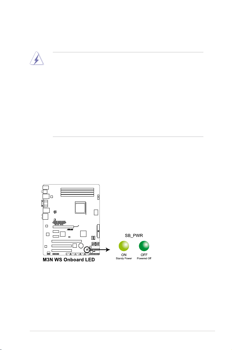
Onboard LED
The motherboard comes with a standby power LED. The green LED lights up
to indicate that the system is ON, in sleep mode, or in soft-off mode. This is a
reminder that you should shut down the system and unplug the power cable before
removing or plugging in any motherboard component. The illustration below shows
the location of the onboard LED.
ASUS M3N WS
2-1
Page 26
2.2 Motherboard overview
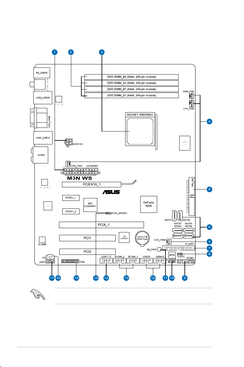
2.2.1 Motherboard layout
Refer to 2.7 Connectors for more information about rear panel connectors and
internal connectors.
2-2 Chapter 2: Hardware information
Page 27

2.2.2 Layout contents
Connectors/Jumpers/Slots Page
1. ATX power connectors (24-pin EATXPWR, 4-pin ATX12V) 2-33
2. DDR2 DIMM slots 2-10
3. CPU Socket AM2/AM2+ 2-5
4. CPU, chassis, and power fan connectors (4-pin CPU_FAN;
3-pin CHA_FAN1-2; 3-pin PWR_FAN)
5. IDE connector (40-1 pin PRI_IDE) 2-27
6. NVIDIA GeForce 8200 Serial ATA connectors
(7-pin SATA 1-4 [red], 7-pin SATA5-6 [black])
7. Floppy disk drive connector (34-1 pin FLOPPY) 2-26
8. Clear RTC RAM (3-pin CLRTC) 2-21
9. System panel connector (20-8 pin PANEL) 2-36
10. Chassis intrusion connector (4-1 pin CHASSIS) 2-32
11. Standby power LED (SB_PWR) 2-1
12. USB connectors (10-1 pin USB78, USB910, USB1112) 2-29
13. IEEE 1394a port connectors (10-1 pin IE1394_1, IE1394_2) 2-30
14. PCI-X speed setting (3-pin PCIX_SPEED1) 2-22
15. TPM connector (20-1 pin TPM) 2-35
16. Optical drive audio connector (4-pin CD) 2-32
17. Front panel audio connector (10-1 pin AAFP) 2-34
2-31
2-28
ASUS M3N WS
2-3
Page 28
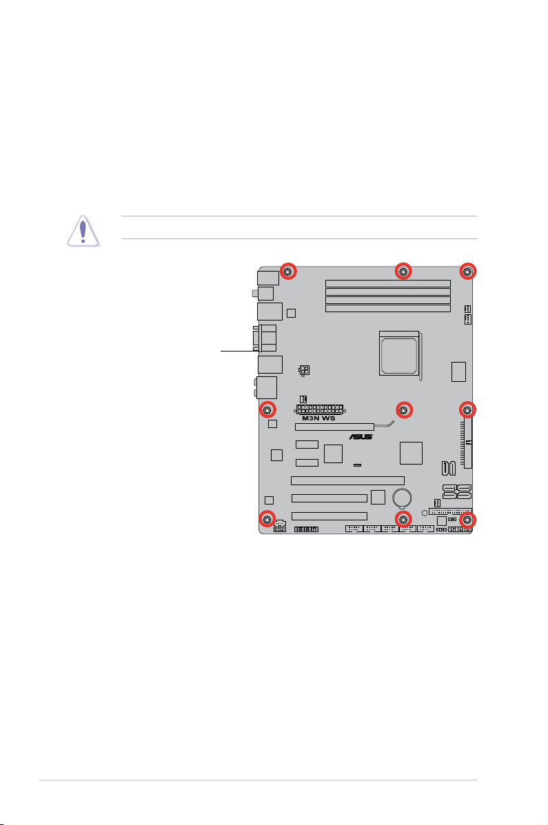
2.2.3 Placement direction
When installing the motherboard, make sure that you place it into the chassis in
the correct orientation. The edge with external ports goes to the rear part of the
chassis as indicated in the image below.
2.2.4 Screw holes
Place nine (9) screws into the holes indicated by circles to secure the motherboard
to the chassis.
Do not overtighten the screws! Doing so can damage the motherboard.
Place this side towards
the rear of the chassis
2-4 Chapter 2: Hardware information
Page 29
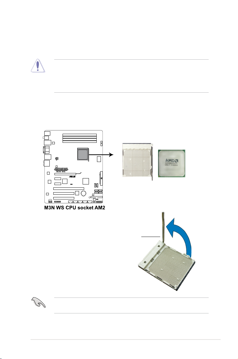
2.3 Central Processing Unit (CPU)
The motherboard comes with an AM2+/AM2 socket designed for AMDAM2+/AM2 socket designed for AMD socket designed for AMDAMD® Socket
AM2+ Phenom™ FX / Phenom / Athlon™ / Sempron™ processors or for SocketPhenom™ FX / Phenom / Athlon™ / Sempron™ processors or for Socket
AM2 Athlon series / Sempron processors.
The AM2+/AM2 socket has a different pinout from the 940-pin socket designed
for the AMD Opteron processor. Make sure you use a CPU designed for the
AM2+/AM2 socket. The CPU ts in only one correct orientation. DO NOT force
the CPU into the socket to prevent bending the connectors on the socket and
damaging the CPU!
2.3.1 Installing the CPU
To install a CPU:
1. Locate the CPU socket on the motherboard.
2. Unlock the socket by pressing the
lever sideways, then lift it up to a
90º angle.
Make sure that the socket lever is lifted up to a 90º angle; otherwise, the CPU
will not t in completely.
ASUS M3N WS
Socket lever
2-5
Page 30
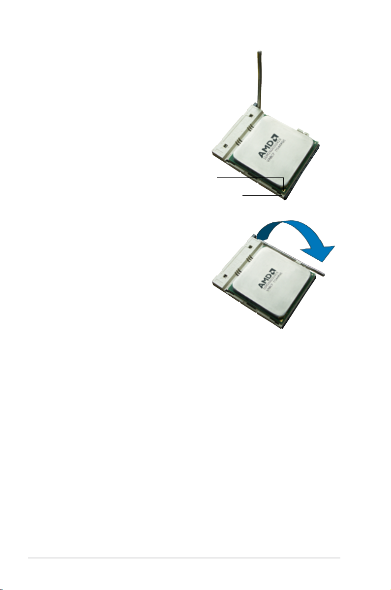
3. Position the CPU above the socket
such that the CPU corner with the
gold triangle matches the socket
corner with a small triangle.
4. Carefully insert the CPU into the
socket until it ts in place.
Gold triangle
Small triangle
5. When the CPU is in place, push
down the socket lever to secure the
CPU. The lever clicks on the side tab
to indicate that it is locked.
6. Install a CPU heatsink and fan
following the instructions that came
with the heatsink package.
2-6 Chapter 2: Hardware information
Page 31

2.3.2 Installing the heatsink and fan
The AMD® Phenom™ FX / Phenom / Athlon™/ Sempron™ processor requires aPhenom™ FX / Phenom / Athlon™/ Sempron™ processor requires aprocessor requires a
specially designed heatsink and fan assembly to ensure optimum thermal condition
and performance.
Make sure that you use only AMD-certied heatsink and fan assembly.
To install the CPU heatsink and fan:
1. Place the heatsink on top of the installed CPU, making sure that the heatsink
ts properly on the retention module base.
•
The retention module base is already installed on the motherboard upon
purchase.
•
You do not have to remove the retention module base when installing the
CPU or installing other motherboard components.
•
If you purchased a separate CPU heatsink and fan assembly, make sure
that a Thermal Interface Material is properly applied to the CPU heatsink or
CPU before you install the heatsink and fan assembly.
CPU fan
CPU heatsink
Retention module base
Retention bracket
Retention bracket lock
Your boxed CPU heatsink and fan assembly should come with installation
instructions for the CPU, heatsink, and the retention mechanism. If the
instructions in this section do not match the CPU documentation, follow the
latter.
ASUS M3N WS 2-7
Page 32

2. Attach one end of the retention bracket
to the retention module base.
3. Align the other end of the retention
bracket (near the retention bracket
lock) to the retention module base.
A clicking sound denotes that the
retention bracket is in place.
Make sure that the fan and
heatsink assembly perfectly ts
the retention mechanism module
base, otherwise you cannot snap
the retention bracket in place.
4. Push down the retention bracket lock
on the retention mechanism to secure
the heatsink and fan to the module
base.
2-8 Chapter 2: Hardware information
Page 33

5. When the fan and heatsink assembly is in place, connect the CPU fan cable
to the connector on the motherboard labeled CPU_FAN.
• Do not forget to connect the CPU fan connector! Hardware monitoring
errors can occur if you fail to plug this connector.
• This connector is backward compatible with 3-pin CPU fans .
ASUS M3N WS 2-9
Page 34

2.4 System memory
2.4.1 Overview
The motherboard comes with four Double Data Rate 2 (DDR2) Dual Inline Memory
Modules (DIMM) sockets.
A DDR2 module has the same physical dimensions as a DDR DIMM but has a
240-pin footprint compared to the 184-pin DDR DIMM. DDR2 DIMMs are notched
differently to prevent installation on a DDR DIMM socket.
The gure illustrates the location of the DDR2 DIMM sockets:
Channel Sockets
Channel A DIMM_A1 and DIMM_A2
Channel B DIMM_B1 and DIMM_B2
2-10 Chapter 2: Hardware information
Page 35

2.4.2 Memory congurations
You may install 512 MB, 1 GB, and 2 GB unbuffered ECC and non-ECC DDR2
DIMMs into the DIMM sockets.
Recommended Memory Congurations
Sockets
Mode
Single-Channel
Dual-channel (1) Populated – Populated –
Dual-channel (2) Populated Populated Populated Populated
• You may install varying memory sizes in Channel A and Channel B. The
• Always install DIMMs with the same CAS latency. For optimum
• If you install four 1 GB memory modules, the system may only recognize
• If you install Windows® XP/Vista 32-bit operation system, a total memory of
• This motherboard does not support memory modules made up of 128 Mb
DIMM_A1
(yellow)
– – Populated –
Populated – – –
system maps the total size of the lower-sized channel for the dual-channel
conguration. Any excess memory from the higher-sized channel is then
mapped for single-channel operation.
compatibility, it is recommended that you obtain memory modules from the
same vendor.
less than 3GB because the address space is reserved for other critical
functions. This limitation appears on Windows® XP/Vista 32-bit operation
system which does not support Physical Address Extension (PAE).
less than 3GB is recommended.
chips.
DIMM_A2
(black)
DIMM_B1
(yellow)
DIMM_B2
(black)
Due to OS limitation, this motherboard can only support up to 8 GB on the
operating systems listed below. You may install a maximum of 2 GB DIMMs on
each slot.
ASUS M3N WS 2-11
Windows® XP Professional x64 Edition
Windows
64-bit
®
Vista x64 Edition
Page 36

M3N WS Motherboard Qualied Vendors Lists (QVL)
DDR2-800MHz capability for AM2 CPU
DIMM socket
Vendor Part No. Size
A-DATA M2OAD6G3H3160G1E53 512MB SS AD29608A8A-25EG N/A N/A • • •
A-DATA M2OAD6G3I4170I1E58 1GB DS AD26908A8A-25EG N/A N/A •
A-DATA M2OAD6H3J4171Q1E52 2GB DS AD20908A8A-25EG N/A A-DATA • • •
Apacer 78.91G9I.9K5 512MB SS AM4B5708JQJS8E N/A APACER • • •
Apacer 78.01GA0.9K5 1GB SS AM4B5808CQJS8E N/A APACER • • •
Apacer 78.A1GA0.9K4 2GB DS AM4B5808CQJS8E 5 APACER • • •
CORSAIR CM2X1024-6400C4 1GB DS Heat-Sink Package 4 N/A •
Crucial BL12864AA804.16FD 1GB DS Heat-Sink Package 4 N/A •
Crucial BL12864AL804.16FD3 1GB DS Heat-Sink Package 4 N/A • •
Crucial BL12864AA804.16FD3 1GB DS Heat-Sink Package 4 N/A • • •
ELPIDA EBE10EE8ABFA-8E-E 1GB SS E1108AB-8E-E(ECC) 5 ELPIDA • •
G.SKILL F2-6400CL4D-2GBPK 1GB DS Heat-Sink Package N/A N/A • • •
G.SKILL F2-6400PHU2-2GBNR 1GB DS Heat-Sink Package N/A N/A • • •
G.SKILL F2-6400CL4D-4GBPK
G.SKILL F2-6400CL5D-4GBPQ
GEIL Heat-Sink Package 2GB DS GE24GB800C5DC 5-5-5-15 N/A • • •
GEIL Heat-Sink Package 2GB DS GE28GB800C5QC 5-5-5-15 N/A • • •
GEIL Heat-Sink Package 2GB DS GE28GB800C4QC 4-4-4-12 N/A • • •
GEIL Heat-Sink Package 2GB DS GE24GB800C4DC 4-4-4-12 N/A • • •
GEIL GL2L128M88BA25AB 2GB DS GB24GB6400C5DC 5-5-5-15 GEIL • • •
Hynix HYMP564U64CP8-S5 512MB SS HY5PS12821CFP-S5 5-5-5 Hynix •
Hynix HYMP512U64CP8-S5 1GB DS HY5PS12821CFP-S5 5-5-5 Hynix • • •
KINGMAX KLDC28F-A8KI5 512MB SS KKA8FEIBF-HJK-25A N/A KINGMAX • •
KINGMAX KLDD48F-ABKI5 1GB DS KKA8FEIBF-HJK-25A N/A KINGMAX • • •
KINGMAX KLDE88F-B8KB5 2GB DS KKB8FFBXF-CFA-25A N/A KINGMAX • • •
KINGSTON KVR800D2N5/512 512MB SS E5108AJBG-8E-E N/A ELPIDA • • •
KINGSTON KVR800D2N6/512 512MB SS E5108AJBG-8E-E 1.8 ELPIDA • • •
KINGSTON
KINGSTON KHX6400D2ULK2/1G 1GB SS Heat-Sink Package N/A N/A • •
KINGSTON KVR800D2N5/1G 1GB DS V59C1512804QBF25 N/A N/A • •
KINGSTON KVR800D2N6/1G 1GB DS E5108AJBG-8E-E 1.8 ELPIDA • • •
KINGSTON KVR800D2N5/2G 2GB DS E1108ACBG-8E-E N/A ELPIDA • • •
NANYA NT512T64U880BY-25C 512MB SS NT5TU64M8BE-25C 5 NANYA • • •
NANYA NT1GT64U8HB0BY-25C 1GB DS NT5TU64M8BE-25C 5 NANYA • • •
NANYA NT1GT64U8HCOBY-25D 1GB DS NT5TU64M8CE-25D N/A NANYA • • •
KHX6400D2LLK2/
1GN(EPP)
SS/
Chip No. CL
DS
4GB
DS Heat-Sink Package 4 N/A • • •
(Kit of 2)
4GB
DS Heat-Sink Package 5 N/A • • •
(Kit of 2)
1GB SS Heat-Sink Package 4-4-4-12 N/A •
Chip
Brand
support (Optional)
A* B* C*
2-12 Chapter 2: Hardware information
Page 37

M3N WS Motherboard Qualied Vendors Lists (QVL)
DDR2-800MHz capability for AM2 CPU (continued)
DIMM socket
Vendor Part No. Size
NANYA NT2GT64U8HC0BY-AC 2GB DS NT5TU128M8CE-AC 5 NANYA • • •
OCZ OCZ2T8002GK 1GB DS Heat-Sink Package N/A N/A • • •
OCZ OCZ2FX800C32GK 1GB DS Heat-Sink Package N/A N/A • •
OCZ OCZ2P800R22GK
OCZ OCZ2P8004GK
PSC AL8E8F73C-8E1 2GB DS A3R1GE3CFF734MAA0E 5 PSC • • •
Qimonda HYS64T256020EU-25F-C2 2GB DS HYB18T1G800C2F-25F 5 QIMONDA • •
Qimonda HYS64T256020EU-2.5-C2 2GB DS HYB18T1G800C2F-2.5 6 QIMONDA • • •
SAMSUNG M378T6553GZS-CF7 512MB SS K4T51083QG 6 SAMSUNG • • •
SAMSUNG M378T2863QZS-CF7 1GB SS K4T1G084QQ 6 SAMSUNG • • •
SAMSUNG M391T2863QZ3-CF7 1GB SS K4T1G084QQ(ECC) 6 SAMSUNG • • •
SAMSUNG M378T2953GZ3-CF7 1GB DS K4T51083QG 6 SAMSUNG • • •
SAMSUNG M378T5263AZ3-CF7 4GB DS K4T2G084QA-HCF7 6 SAMSUNG • • •
SAMSUNG M391T5663QZ3-CF7 2GB DS K4T1G084QQ 6 SAMSUNG • • •
SAMSUNG M378T5663QZ3-CF7 2GB DS K4T1G084QQ(ECC) 6 SAMSUNG • • •
Super
Talent
Super
Talent
Aeneon AET760UD00-25DC08X 1GB SS AET03R25DC 5 Aeneon • • •
Aeneon AET760UD00-25DB97X 1GB DS AET93R25DB N/A Aeneon • • •
Aeneon AET860UD00-25DC08S 2GB DS AET02R25DC N/A Aeneon • • •
Aeneon AET860UD00-25DC08X 2GB DS AET03R25DC 5 Aeneon • • •
Asint SLY2128M8-JGE 1GB SS DDRII1208-GE N/A Asint • • •
Asint SLZ2128M8-JGE 2GB DS DDRII1208-GE N/A Asint • • •
CENTURY 28V2H8 512MB SS HY5PS12821BFP-S5 N/A Hynix • •
CENTURY 28VOH8 1GB DS HY5PS12821BFP-S5 N/A Hynix • •
Elixir M2Y1G64TU8HB0B-25C 1GB DS N2TU51280BE-25C 5 Elixir • • •
Oci 04701G16CZ5D2A 1GB DS 64M8PC6400 5 Jnnity • • •
Patriot PSD21G8002 1GB DS PM64M8D2BU-25PAC 5 Patriot •
Patriot PSD22GB002 2GB DS PM128M8D2BU-25KC 5 Patriot • • •
UMAX D48001GP3-63BJU 1GB DS U2S12D30TP-8E N/A UMAX • • •
UMAX D48002GP0-73BCU 2GB DS U2S12D30TP-8E N/A UMAX •
T800UA12C4 512MB SS Heat-Sink Package N/A N/A • • •
T800UB1GC4 1GB DS Heat-Sink Package N/A N/A • • •
SS/
Chip No. CL Chip Brand
DS
2GB
DS Heat-Sink Package 4 N/A • • •
(Kit of 2)
4GB
DS Heat-Sink Package 5-4-4 N/A • • •
(Kit of 2)
support (Optional)
A* B* C*
ASUS M3N WS 2-13
Page 38

M3N WS Motherboard Qualied Vendors Lists (QVL)
DDR2-667MHz capability for AM2 CPU
DIMM socket
Vendor Part No. Size
A-DATA M2OAD5G3H3166I1C52 512MB SS AD29608A8A-3EG 5 A-DATA • •
A-DATA M2OAD5G3I4176I1C52 1GB DS AD29608A8A-3EG 5 A-DATA •
A-DATA M2ONY5H3J4170I1C5Z 2GB DS NT5TU128M8BJ-3C N/A N/A •
Apacer 78.01G9O.9K5 1GB SS AM4B5808CQJS7E N/A APACER •
Apacer 78.91G92.9K5 512MB SS AM4B5708JQJS7E N/A APACER •
Apacer 78.A1G9O.9K4 2GB DS AM4B5808CQJS7E N/A APACER • •
CORSAIR VS 512MB667D2 512MB SS 64M8CFEG N/A N/A • •
CORSAIR VS1GB667D2 1GB DS 64M8CFEG N/A N/A • •
crucial BL6464AA663.8FD 512MB SS Heat-Sink Package 3 N/A • •
crucial BL12864AA663.16FD 1GB DS Heat-Sink Package 3 N/A • • •
ELPIDA EBE51UD8AEFA-6E-E 512MB SS E5108AE-6E-E 5 ELPIDA • • •
G.SKILL F2-5300CL5D-4GBMQ
G.SKILL F2-5400PHU2-2GBNT
GEIL GX21GB5300SX 1GB DS Heat-Sink Package 3-4-4-8 N/A • • •
GEIL GX22GB5300LX 2GB DS Heat-Sink Package 5-5-5-15 N/A • • •
GEIL GX24GB5300LDC
Hynix HYMP 512U64CP8-Y5 1GB DS HY5PS12821CFP-Y5 5 Hynix • • •
Kingmax KLCC28F-A8KB5 512MB SS KKEA88B4LAUG-29DX 5 KINGMAX • • •
Kingmax KLCD48F-A8KB5 1GB DS KKEA88B4LAUG-29DX 5 KINGMAX •
KINGSTON KVR667D2N5/ 512 512MB SS D6408TEBGGL3U 5 KINGSTON • •
KINGSTON KVR667D2E5/1G 1GB DS E5108AGBG-6E-E N/A ELPIDA • • •
KINGSTON KVR667D2E5/2G 2GB DS D9HNL N/A MICRON • • •
KINGSTON KVR667D2N5/1G 1GB DS E5108AGBG-6E-E N/A KINGSTON • • •
KINGSTON KVR667D2N5/2G 2GB DS E1108AB-6E-E N/A ELPIDA • •
KINGSTON KVR667D2N5/2G 2GB DS HY5PS1G831CFP-Y5 N/A Hynix • • •
NANYA NT 512T64U88B0BY-3C 512MB SS NT5TU64M8BE-3C 5 NANYA • • •
NANYA NT2GT64U8HB0JY-3C 2GB DS NT5TU128M8BJ-3C 5 NANYA • • •
PSC AL7E8E63J-6E1 1GB DS A3R12E3JFF719A9T02 5 PSC • • •
Qimonda HYS64T256020EU-3S-C2 2GB DS HYB18T1GB00C2F-3S 5 QIMONDA • •
SAMSUNG M378T6553EZS-CE6 512MB SS K4T51083QE 5 SAMSUNG • •
SAMSUNG M378T2953EZ3-CE6 1GB DS K4T51083QE 5 SAMSUNG • • •
SAMSUNG M378T5263AZ3-CE6 4GB DS K4T2G084QA-HCE6 5 SAMSUNG • •
Super
Talent
Super
Talent
Transcend JM667QLU-1G 1GB SS TQ243ECF8 5 Transcend • •
T6UA 512C5 512MB SS Heat-Sink Package 5 N/A • •
T6UB1GC5 1GB DS Heat-Sink Package 5 N/A • • •
SS/
Chip No. CL
DS
4GB
DS Heat-Sink Package 5-5-5-15 N/A • •
(Kit of 2)
2GB
DS D264M8GCF 5-5-5-15 G.SKILL • •
(Kit of 2)
4GB
DS Heat-Sink Package 5-5-5-15 N/A • • •
(Kit of 2)
Chip
Brand
support (Optional)
A* B* C*
2-14 Chapter 2: Hardware information
Page 39

M3N WS Motherboard Qualied Vendors Lists (QVL)
DDR2-667MHz capability for AM2 CPU (continued)
DIMM socket
Vendor Part No. Size
Transcend JM667QLU-2G 2GB DS TQ243ECF8 5 Transcend • • •
TwinMOS 8D-23JK5M2ETP 512MB SS TMM6208G8M30C 5 TwinMOS •
Aeneon AET660UD00-30DB97X 512MB SS AET93R300B 5 AENEON • • •
Aeneon AET760UD00-30B97X 1GB DS AET93R30DB 5 AENEON • •
Aeneon AET860UD00-30D 2GB DS AET02R30DC 5 AENEON • • •
Aeneon AET860UD00-30DB08X 2GB DS AET03F30DB 5 AENEON • •
Asint SLX264M8-J6E 512MB SS DDRII6408-6E N/A Asint •
Asint SLY2128M8-J6E 1GB SS DDRII1208-6E N/A Asint • • •
CENTURY 26V2H8 512MB SS HY5PS12821CFP-Y5 5 Hynix •
CENTURY 26VOH8 1GB DS HY5PS12821CFP-Y5 5 Hynix • •
Kingbox N/A 1GB SS EPD2128082200E-4 N/A Kingbox • • •
Kingbox N/A 1GB DS EPD264082200E-4 N/A N/A •
Kingbox N/A 1GB DS EPD264082200N-4 N/A Kingbox • • •
MDT M 512-667-8 512MB SS 18D 51280D-30648 4 MDT • • •
MDT M924-667-16 1GB DS 18D 51280D-30646E 4 MDT • •
MDT M924-667-16A 1GB DS 18 51200D-30646 4 MDT • •
Patriot PSD2 51266781 512MB SS PM64M8D2BU-3KC N/A N/A • • •
Patriot PSD21G6672 1GB DS PM64M8D2BU-3PAC 5 Patriot • • •
UMAX D46701GP3-63BJU 1GB DS U2S12D30TP-6E N/A UMAX • • •
UMAX D46702GP0-73BCU 2GB DS U2S24D30TP-6E N/A UMAX •
SS/
Chip No. CL
DS
Chip
Brand
support (Optional)
A* B* C*
Side(s): SS - Single-sided DS - Double-sided
DIMM support:
• A*: Supports one module inserted into either slot as Single-channel
memory conguration.
• B*: Supports two modules inserted into either the yellow slots or the black
slots as one pair of Dual-channel memory conguration.
• C*: Supports four modules inserted into both the yellow slots and the
black slots as two pairs of Dual-channel memory conguration.
Visit the ASUS website for the latest QVL.
ASUS M3N WS 2-15
Page 40

2.4.3 Installing a DDR2 DIMM
Make sure to unplug the power supply before adding or removing DIMMs or
other system components. Failure to do so may cause severe damage to both
the motherboard and the components.
1. Unlock a DDR2 DIMM socket
by pressing the retaining clips
outward.
2. Align a DIMM on the socket
such that the notch on the DIMM
matches the break on the socket.
1
Unlocked retaining clip
A DDR2 DIMM is keyed with a notch so that it ts in only one direction. DO NOT
force a DIMM into a socket to avoid damaging the DIMM.
2
DDR2 DIMM notch
1
3. Firmly insert the DIMM into the
3
socket until the retaining clips snap
back in place and the DIMM is
properly seated.
Locked Retaining Clip
2.4.4 Removing a DDR2 DIMM
Follow these steps to remove a DIMM.
1. Simultaneously press the
retaining clips outward to unlock
the DIMM.
Support the DIMM lightly with your ngers when pressing the retaining clips.
The DIMM might get damaged when it ips out with extra force.
1
2. Remove the DIMM from the socket.
2-16 Chapter 2: Hardware information
2
1
DDR2 DIMM notch
Page 41

2.5 Expansion slots
In the future, you may need to install expansion cards. The following sub-sections
describe the slots and the expansion cards that they support.
Make sure to unplug the power cord before adding or removing expansion
cards. Failure to do so may cause you physical injury and damage motherboard
components.
2.5.1 Installing an expansion card
To install an expansion card:
1. Before installing the expansion card, read the documentation that came with
it and make the necessary hardware settings for the card.
2. Remove the system unit cover (if your motherboard is already installed in a
chassis).
3. Remove the bracket opposite the slot that you intend to use. Keep the screw
for later use.
4. Align the card connector with the slot and press rmly until the card is
completely seated on the slot.
5. Secure the card to the chassis with the screw you removed earlier.
6. Replace the system cover.
2.5.2 Conguring an expansion card
After installing the expansion card, congure the it by adjusting the software
settings.
1. Turn on the system and change the necessary BIOS settings, if any. See
Chapter 3 for information on BIOS setup.
2. Assign an IRQ to the card. Refer to the tables on the next page.
3. Install the software drivers for the expansion card.
When using PCI cards on shared slots, ensure that the drivers support “Share
IRQ” or that the cards do not need IRQ assignments; otherwise, conicts will
arise between the two PCI groups, making the system unstable and the card
inoperable.
ASUS M3N WS 2-17
Page 42

2.5.3 Interrupt assignments
Standard interrupt assignments
IRQ Priority Standard function
0 1 System Timer
1 2 Keyboard Controller
2 – Redirect to IRQ#9
3 11 Reserved
4 12 Reserved
5 13 IRQ Holder for PCI Steering*
6 14 Floppy Disk Controller
7 15 IRQ Holder for PCI Steering*
8 3 System CMOS/Real Time Clock
9 4 IRQ Holder for PCI Steering*
10 5 IRQ Holder for PCI Steering*
11 6 IRQ Holder for PCI Steering*
12 7 Reserved
13 8 Numeric Data Processor
14 9 Primary IDE Channel
* These IRQs are usually available for ISA or PCI devices.
IRQ assignments for this motherboard
A B C D E F G H
PCIE x16_1 shared shared shared shared – – – –
USB 1.0 controller 1 – – – shared – – – –
USB 1.0 controller 2 – – – shared – – – –
USB 1.0 controller 3 – – – shared – – – –
USB 1.0 controller 4 – – – shared – – – –
USB 2.0 controller – – – shared – – – –
HD audio shared – – – – – – –
2-18 Chapter 2: Hardware information
Page 43

2.5.4 PCI slots
The PCI slots support cards such as a LAN card, SCSI card, USB card, and other
cards that comply with PCI specications. Refer to the gure on the next page for
the location of the slots.
2.5.5 PCI-X slot
The PCI-X slot supports cards such as a LAN card, SCSI card, USB card, and
other cards that comply with PCI-X 1.0 specications. Refer to the gure below forRefer to the gure below for
the location of the slot.
2.5.6 PCI Express x1 slots
This motherboard supports PCI Express x1 network cards, SCSI cards and other
cards that comply with the PCI Express specications. Refer to the gure on the
next page for the location of the slots.
2.5.7 PCI Express 2.0 x16 slot
This motherboard supports PCI Express 2.0 x16 graphics cards that complies with
the PCI Express specications. Refer to the gure below for the location of the slot.
PCI Express 2.0 x16_1 slot
PCI Express x1_1 slot
PCI Express x1_2 slot
ASUS M3N WS 2-19
PCI-X slot
PCI_1 slot
PCI_2 slot
Page 44

• Currently, only Windows® Vista operation system supports Hybrid SLI™
mode.
• Currently, only NVIDIA® GeForce® 8500 GT and GeForce® 8400 GS
graphics cards support GeForce Boost function under Hybrid SLI™ mode.
• Currently, only NVIDIA® GeForce® 9800 GX2 and GeForce® 9800 GTX
graphics cards support Hybrid Power function under Hybrid SLI™ mode.
• Use only the onboard HDMI/DVI/D-Sub port for video signal output when
activating the Hybird Power function under Hybrid SLI™ mode.
• Visit www.nvidia.com/hybridsli for more information about Hybrid SLI™
support.
• This motherboard supports the ASUS SASsaby SAS RAID card series
(optional) for SAS hard disk drive expansion. Install the card to the PCIe
x16 2.0 slot (blue) only.
2-20 Chapter 2: Hardware information
Page 45

2.6 Jumpers
1. Clear RTC RAM (3-pin CLRTC)
This jumper allows you to clear the Real Time Clock (RTC) RAM in
CMOS. You can clear the CMOS memory of date, time, and system setup
parameters by erasing the CMOS RTC RAM data. The onboard button
cell battery powers the RAM data in CMOS, which include system setup
information such as system passwords.
To erase the RTC RAM
1. Turn OFF the computer and unplug the power cord.
2. Move the jumper cap from pins 1-2 (default) to pins 2-3. Keep the cap on
pins 2-3 for about 5–10 seconds, then move the cap back to pins 1-2.
3. Plug the power cord and turn ON the computer.
4. Hold down the <Del> key during the boot process and enter BIOS setup
to re-enter data.
Except when clearing the RTC RAM, never remove the cap on CLRTC jumper
default position. Removing the cap will cause system boot failure!
• If the steps above do not help, remove the onboard battery and move
the jumper again to clear the CMOS RTC RAM data. After the CMOS
clearance, reinstall the battery.
• You do not need to clear the RTC when the system hangs due to
overclocking. For system failure due to overclocking, use the C.P.R. (CPU
Parameter Recall) feature. Shut down and reboot the system so the BIOS
can automatically reset parameter settings to default values.
• Due to the chipset limitation, AC power off is required prior using C.P.R.
function. You must turn off and on the power supply or unplug and plug the
power cord before reboot the system.
ASUS M3N WS 2-21
Page 46

2. PCI-X Speed setting (3-pin PCIX_SPEED1)
This jumper allows you to set the PCI-X slot’s maximum frequency capability.
The jumper cap on pins 1-2: 133 MHz capability for the PCI-X slot.
The jumper cap on pins 2-3: 100 MHz capability for the PCI-X slot.
2-22 Chapter 2: Hardware information
Page 47

2.7 Connectors
2.7.1 Rear panel connectors
1. PS/2 keyboard port (purple). This port is for a PS/2 keyboard.
2. Coaxial S/PDIF Out port. This port connects an external audio output device
via a coaxial S/PDIF cable.
3. LAN2 (RJ-45) port. Supported by Realtek® 8111C Gigabit LAN controller,
this port allows Gigabit connection to a Local Area Network (LAN) through a
network hub. Refer to the table below for the LAN port LED indications.
4. VGA port. This port is for a VGA monitor or other VGA-compatible devices.
5. LAN1 (RJ-45) port. Supported by Realtek® 8111C Gigabit LAN controller,
this port allows Gigabit connection to a Local Area Network (LAN) through a
network hub. Refer to the table below for the LAN port LED indications.
LAN port LED indications
Activity/Link LED Speed LED
Status Description Status Description
OFF No link OFF 10 Mbps connection
ORANGE Linked ORANGE 100 Mbps connection
BLINKING Data activity GREEN 1 Gbps connection
ACT/LINK
LED
LAN port
SPEED
LED
6. Center/Subwoofer port (orange). This port connects the center/subwoofer
speakers.
7. Rear Speaker Out port (black). This port connects the rear speakers in a
4-channel, 6-channel, or 8-channel audio conguration.
8. Line In port (light blue). This port connects the tape, CD, DVD player, or
other audio sources.
9. Line Out port (lime). This port connects a headphone or a speaker. In
4-channel, 6-channel, and 8-channel conguration, the function of this port
becomes Front Speaker Out.
10. Microphone port (pink). This port connects a microphone.
11. Side Speaker Out port (gray). This port connects the side speakers in an
8-channel audio conguration.
ASUS M3N WS 2-23
Page 48

Refer to the audio conguration table below for the function of the audio ports in
2, 4, 6, or 8-channel conguration.
Audio 2, 4, 6, or 8-channel conguration
Port
Light Blue Line In Line In Line In Line In
Lime Line Out Front Speaker Out Front Speaker Out Front Speaker Out
Pink Mic In Mic In Mic In Mic In
Orange – – Center/Subwoofer Center/Subwoofer
Black – Rear Speaker Out Rear Speaker Ou Rear Speaker Out
Gray – – – Side Speaker Out
12. USB 2.0 ports 1 and 2. These 4-pin Universal Serial Bus (USB) ports are
13. HDMI Out port. This port is for a high-denition multimedia interface (HDMI)
Headset
2-channel
4-channel 6-channel 8-channel
available for connecting USB 2.0 devices.
connector.
• This motherboard comes with dual-VGA outputs that features different
displays on 2 monitors at the same time if you connect 2 monitors to both
the onboard VGA and HDMI ports.
• With the bundled HDMI-to-DVI conversion adapter, this motherboard can
also support DVI output.
• Playback of HD DVD and Blu-Ray Discs
The speed and bandwidth of the CPU/Memory, DVD player, and drivers will
affect the playback quality. Following is a conguration example for your
reference. Using the CPU/Memory of higher speed and bandwidth with the
higher-version DVD player and drivers will upgrade the playback quality.
CPU: AMD K8 M2 Athlon64 ADH1600IAA5DH/1M Rev.F3
DIMM: DDR2-800 1G x1
HDD: Maxtor 6Y120M0 (SATA150)
ODD: LG GBW-H10N
• To play HD DVD or Blu-Ray Disc, make sure to use an HDCP compliant
monitor.
Before enabling the HybridPower™ function, ensure that you have connected
your display to the onboard VGA port or the HDMI/DVI port at the rear panel.
14. USB 2.0 ports 3 and 4. These 4-pin Universal Serial Bus (USB) ports are
available for connecting USB 2.0 devices.
15. Optical S/PDIF Out port.Optical S/PDIF Out port. This port connects an external audio output device
via a optical S/PDIF cable.
16. USB 2.0 ports 5 and 6. These 4-pin Universal Serial Bus (USB) ports are
available for connecting USB 2.0 devices.
2-24 Chapter 2: Hardware information
Page 49

Troubleshooting on HDTV overscaling or underscaling:
If your desktop is extending beyond the viewable display area or the desktop or
image is not lling the entire display area while using the onboard HDMI out port
and the HDMI cable, you can resize the desktop appearing on your HDTV screen.
To resize your HDTV desktop:
1. Install NVIDIA Chipset Driver Program from the motherboard support DVD.
2. Right-click the desktop and select NVIDIA Control Panel.
3. Under Video & Television, select Resize HDTV desktop.
4. Select Resize my desktop and click Resize Desktop.
5. A full-screen adjustment tool
appears. Use the scroll bar to
resize the desktop to t your display
device. Click OK to exit.
The Resize my desktop function in the NVIDIA Control Panel appears only
when you are using an HDTV compliance resolution such as 480i, 720i, or
1080i.
ASUS M3N WS 2-25
Page 50

2.7.2 Internal connectors
1. Floppy disk drive connector (34-1 pin FLOPPY)
This connector is for the provided oppy disk drive (FDD) signal cable. Insert
one end of the cable to this connector, then connect the other end to the
signal connector at the back of the oppy disk drive.
Pin 5 on the connector is removed to prevent incorrect cable connection when
using a FDD cable with a covered Pin 5.
2-26 Chapter 2: Hardware information
Page 51

2. IDE connector (40-1 pin PRI_IDE)
The onboard IDE connector is for the Ultra DMA 133/100 signal cable. There
are three connectors on each Ultra DMA 133/100 signal cable: blue, black,
and gray. Connect the blue connector to the motherboard’s IDE connector,
then select one of the following modes to congure your device.
Drive jumper setting Mode of
Single device Cable-Select or Master – Black
Cable-Select
Two devices
• Pin 20 on the IDE connector is removed to match the covered hole on the
Ultra DMA cable connector. This prevents incorrect insertion when you
connect the IDE cable.
• Use the 80-conductor IDE cable for Ultra DMA 133/100 IDE devices.
If any device jumper is set as “Cable-Select,” make sure all other device
jumpers have the same setting.
Master Master Black or gray
Slave Slave
device(s)
Master Black
Slave Gray
Cable connector
ASUS M3N WS 2-27
Page 52

3. NVIDIA® GeForce 8200 Serial ATA connectors
(7-pin SATA1-4 [red], 7-pin SATA5-6 [black])
These connectors are for the Serial ATA signal cables for Serial ATA hard disk
and optical disk drives.
If you install SATA hard disk drives to the SATA connectors, you can create
a RAID 0, RAID 1, RAID 0+1, RAID 5, or JBOD conguration through the
onboard NVIDIA® GeForce 8200 controller.
• SATA1-4 connectors are set to [IDE] by default. If you intend to create
a Serial ATA RAID set using these connectors, set the SATA Operation
Mode item in the BIOS to [RAID].
• Before creating a RAID set, refer to the manual bundled in the motherboard
support DVD.
• SATA 5-6 connectors support AHCI mode and RAID mode only. Make sure
to install the AHCI driver or RAID driver in the bundled support DVD before
connecting devices to SATA 5-6 connectors. Otherwise, the devices will not
work.
• Due to chipset limitation, when set any of SATA ports to RAID mode, all
SATA ports run at RAID mode together.
• You must install the Windows XP® Service Pack 1 before using Serial ATA
hard disk drives. The Serial ATA RAID feature (RAID 0 and RAID 1) is
available only if you are using Windows XP® or later version.
Right angle side
Connect the right-angle side of SATA signal
cable to SATA device. Or you may connect
the right-angle side of SATA cable to the
onboard SATA port to avoid mechanical
conict with huge graphics cards.
2-28 Chapter 2: Hardware information
Page 53

4. USB connectors (10-1 pin USB 78, USB910, USB1112)
These connectors are for USB 2.0 ports. Connect the USB module cable
to any of these connectors, then install the module to a slot opening at the
back of the system chassis. These USB connectors comply with USB 2.0
specication that supports up to 480 Mbps connection speed.
Never connect a 1394 cable to the USB connectors. Doing so will damage the
motherboard!
You can connect the front panel USB cable to the ASUS Q-Connector (USB,
blue) rst, and then install the Q-Connector (USB) to the USB connector
onboard if your chassis supports front panel USB ports.
ASUS M3N WS 2-29
Page 54

5. IEEE 1394a port connector (10-1 pin IE1394_1, IE1394_2)
This connector is for a IEEE 1394a port. Connect the IEEE 1394a module
cable to this connector, then install the module to a slot opening at the back
of the system chassis.
Never connect a USB cable to the IEEE 1394a connector. Doing so will damage
the motherboard!
You can connect the front panel 1394 cable to the ASUS Q-Connector (1394,
red) rst, and then install the Q-Connector (1394) to the 1394 connector
onboard if your chassis supports front panel 1394 ports.
2-30 Chapter 2: Hardware information
Page 55

6. CPU, chassis, and power fan connectors (4-pin CPU_FAN; 3-pin
CHA_FAN1-2; 3-pin PWR_FAN)
The fan connectors support cooling fans of 350 mA~2000 mA (24 W max.)
or a total of 1 A~7 A (84 W max.) at +12V. Connect the fan cables to the fan
connectors on the motherboard, making sure that the black wire of each
cable matches the ground pin of the connector.
Do not forget to connect the fan cables to the fan connectors. Insufcient air
ow inside the system may damage the motherboard components. These are
not jumpers! Do not place jumper caps on the fan connectors!
Only the CPU_FAN and CHA_FAN1-2 connectors support the ASUS Q FAN2
feature.
ASUS M3N WS
2-31
Page 56

7. Chassis intrusion connector (4-1 pin CHASSIS)
This connector is for a chassis-mounted intrusion detection sensor or switch.
Connect one end of the chassis intrusion sensor or switch cable to this
connector. The chassis intrusion sensor or switch sends a high-level signal to
this connector when a chassis component is removed or replaced. The signal
is then generated as a chassis intrusion event.
By default , the pin labeled “Chassis Signal” and “Ground” are shorted with
a jumper cap. Remove the jumper caps only when you intend to use the
chassis intrusion detection feature.
8. Optical drive audio connector (4-pin CD)
These connectors allow you to receive stereo audio input from sound sources
such as a CD-ROM, TV tuner, or MPEG card.
2-32 Chapter 2: Hardware information
Page 57

9. ATX power connectors (24-pin EATXPWR; 4-pin ATX12V)
These connectors are for ATX power supply plugs. The power supply plugs
are designed to t these connectors in only one orientation. Find the proper
orientation and push down rmly until the connectors completely t.
• For a fully congured system, we recommend that you use a power supply
unit (PSU) that complies with ATX 12 V Specication 2.0 (or later version)
and provides a minimum power of 600 W.
• Do not forget to connect the 4-pin ATX +12 V power plug; otherwise, the
system will not boot.
• Use of a PSU with a higher power output is recommended when
conguring a system with more power-consuming devices. The system
may become unstable or may not boot up if the power is inadequate.
• If you are uncertain about the minimum power supply requirement for your
system, refer to the Recommended Power Supply Wattage Calculator
at http://support.asus.com/PowerSupplyCalculator/PSCalculator.
aspx?SLanguage=en-us for details.
• The ATX 12 V Specication 2.0-compliant (500W) PSU has been tested
to support the motherboard power requirements with the following
conguration:
CPU: AMD FX-62
Memory 1024 MB DDR2-800 (x4)
Graphics card: PCI Express x16 NVIDIA 7900GTX
Serial ATA device: SATA hard disk drive (x2)
Optical drives: DVD-RW
ASUS M3N WS
2-33
Page 58

10. Front panel audio connector (10-1 pin AAFP)
This connector is for a chassis-mounted front panel audio I/O module that
supports HD Audio standard. Connect one end of the front panel audio I/O
module cable to this connector.
We recommend that you connect a high-denition front panel audio module to
this connector to avail of the motherboard’s high-denition audio capability.
2-34 Chapter 2: Hardware information
Page 59

11. TPM connector (20-1 pin TPM) [Optional]
This connector supports a Trusted Platform Module (TPM) system, which can
securely store keys, digital certicates, passwords, and data. A TPM system
also helps enhance network security, protects digital identities, and ensures
platform integrity.
ASUS M3N WS
2-35
Page 60

12. System panel connector (20-8 pin PANEL)
This connector supports several chassis-mounted functions.
•
System power LED (2-pin PLED)
This 2-pin connector is for the system power LED. Connect the chassis
power LED cable to this connector. The system power LED lights up when
you turn on the system power, and blinks when the system is in sleep mode.
•
Hard disk drive activity LED (2-pin IDE_LED)
This 2-pin connector is for the HDD Activity LED. Connect the HDD Activity
LED cable to this connector. The IDE LED lights up or ashes when data is
read from or written to the HDD.
•
System warning speaker (4-pin SPEAKER)
This 4-pin connector is for the chassis-mounted system warning speaker. The
speaker allows you to hear system beeps and warnings.
•
ATX power button/soft-off button (2-pin PWRSR)
This connector is for the system power button. Pressing the power button
turns the system on or puts the system in sleep or soft-off mode depending
on the BIOS settings. Pressing the power switch for more than four seconds
while the system is ON turns the system OFF.
•
Reset button (2-pin RESET)
This 2-pin connector is for the chassis-mounted reset button for system
reboot without turning off the system power.
2-36 Chapter 2: Hardware information
Page 61

13. ASUS Q-Connector (system panel)
You can use the ASUS Q-Connector to connect/disconnect chassis front
panel cables in a few steps. Refer to the instructions below to install the
ASUS Q-Connector.
1. Connect the front panel cables to the
ASUS Q-Connector.
Refer to the labels on the
Q-Connector to know the detailed pin
denitions, then match them to the
respective front panel cable labels.
2. Install the ASUS Q-Connector to the
system panel connector, making sure
the orientation matches the labels on
the motherboard.
3. The front panel functions are now
enabled. The gure shows the
Q-Connector properly installed on the
motherboard.
ASUS M3N WS
2-37
Page 62

2.8 G.P. Diagnosis card installation
2.8.1 G.P. Diagnosis card layout
LED 0 and 1
Power Switch. Press
to turn ON or OFF the
2.8.2 Installing G.P. Diagnosis card
1. Locate the TPM connector (20-1
pin TPM) on the motherboard.
computer.
Reset Button.
Press to restart the
computer.
Card connector
Make sure to turn off the power supply unit before instaling the diagnosis card to
avoid electrical shock hazard.
2. With the LEDs of the diagnosis
card facing to the DIMM sockets,
align the card connector with the
TPM connector and press rmly
until the card sits on the connector
completely.
2-38 Chapter 2: Hardware information
Page 63

3. You may also install the G.P.
Diagnosis card via a bundled 90degree TPM adaptor for a more
exible application.
2.8.3 G.P. Diagnosis card check codes
C0 Early chipset initialization
C1 Detect memory
C3 Expand compressed BIOS code to DRAM
25 Early PCI initialization
26 1. Set clock generator and disable unnecessary or unused clock
2. Init onboard PWM
3. Init onboard H/W monitor devices
2B Invoke Video BIOS
2D 1. Initialize double-byte language font (optional)
2. Put information on screen display, including Award title, CPU type, Cpu speed, full
screen logo.
4E 1. Program MTRR of CPU
2. Initialize L2 cache for CPU & program CPU with proper cacheable range.
3. Initialize APIC
50 Initialize USB Keyboard & Mouse.
52 Test all memory
75 Detect & install all IDE devices: HDD, LS120, ZIP, CD-ROM...
7F Switch back to text mode if full screen logo is supported.
- If errors occur, report errors & wait for keys.
- If no errors occur or F1 key is pressed to continue: Clear EPA or customizatoin
logo.
8B 1. Invoke all ISA adapter ROMs
2. Invoke all PCI ROMs (except VGA)
ASUS M3N WS
(continued on the next page)
2-39
Page 64

94 1. Enable L2 cache
2. Program Daylight Saving
3. Program boot up speed
4. Chipset nal initialization
5. Power management nal initialization
6. Clear screen & display summary table.
96 1. Build MP table.
2. Builid & update ESCD.
3. Set CMOS century to 20h or 19h
4. Load CMOS time into DOS timer tick.
5. Build MSIRQ routing table.
0F Reserved
F1 Sleep state S1
F3 Sleep state S3
F4 Sleep state S4
F5 Sleep state S5
2-40 Chapter 2: Hardware information
Page 65

2.9 Starting up for the rst time
1. After making all the connections, replace the system case cover.
2. Be sure that all switches are off.
3. Connect the power cord to the power connector at the back of the system
chassis.
4. Connect the power cord to a power outlet that is equipped with a surge
protector.
5. Turn on the devices in the following order:
a. Monitor
b. External SCSI devices (starting with the last device on the chain)
c. System power
6. After applying power, the system power LED on the system front panel case
lights up. For systems with ATX power supplies, the system LED lights up
when you press the ATX power button. If your monitor complies with “green”
standards or if it has a “power standby” feature, the monitor LED may light up
or switch between orange and green after the system LED turns on.
The system then runs the power-on self tests or POST. While the tests are
running, the BIOS beeps or additional messages appear on the screen.
If you do not see anything within 30 seconds from the time you turned on
the power, the system may have failed a power-on test. Check the jumper
settings and connections or call your retailer for assistance.
BIOS beep codes
BIOS Beep Description
One short beep No keyboard detected
One continuous beep followed by two
short beeps then a pause (repeated)
One continuous beep followed by three
short beeps
One continuous beep followed by four
short beeps
No memory detected
No VGA detected
Hardware component failure
7. At power on, hold down the <Delete> key to enter the BIOS Setup. Follow the
instructions in Chapter 3.
ASUS M3N WS
2-41
Page 66

2.10 Turning off the computer
2.10.1 Using the OS shut down function
If you are using Windows® XP:
1. Click the Start button then select Turn Off Computer.
2. Click the Turn Off button to shut down the computer.
3. The power supply should turn off after Windows® shuts down.
If you are using Windows® Vista™:
1. Click the Start button then select ShutDown.
2. The power supply should turn off after Windows® shuts down.
2.10.2 Using the dual function power switch
While the system is ON, pressing the power switch for less than four seconds puts
the system to sleep mode or to soft-off mode, depending on the BIOS setting.
Pressing the power switch for more than four seconds lets the system enter the
soft-off mode regardless of the BIOS setting. Refer to section 3.5 Power Menu in
Chapter 3 for details.
2-42 Chapter 2: Hardware information
Page 67

This chapter tells how to change the
system settings through the BIOS Setup
menus. Detailed descriptions of the BIOS
parameters are also provided.
BIOS setup
3
Page 68

Chapter summary
3
3.1 Managing and updating your BIOS ............................................ 3-1
3.2 BIOS setup program .................................................................. 3-11
3.3 Main menu .................................................................................. 3-15
3.4 Advanced menu ......................................................................... 3-20
3.5 Power menu ................................................................................ 3-31
3.6 Boot menu .................................................................................. 3-35
3.7 Tools menu ................................................................................. 3-39
3.8 Exit menu .................................................................................... 3-42
ASUS M3N WS
Page 69

3.1 Managing and updating your BIOS
The following utilities allow you to manage and update the motherboard Basic
Input/Output System (BIOS) setup.
1. ASUS Update (Updates the BIOS in Windows® environment.)
2. ASUS EZ Flash 2 (Updates the BIOS using a oppy disk or USB ash disk.)
3. AwardBIOS Flash Utility (Updates the BIOS using a bootable oppy disk or
a USB ash disk.)
4. ASUS CrashFree BIOS 3 (Updates the BIOS using a bootable oppy disk,
USB ash disk or the motherboard support DVD when the BIOS le fails or
gets corrupted.)
Refer to the corresponding sections for details on these utilities.
Save a copy of the original motherboard BIOS le to a bootable USB ash
disk in case you need to restore the BIOS in the future. Copy the original
motherboard BIOS using the ASUS Update or Award BIOS Flash utilities.
3.1.1 ASUS Update utility
The ASUS Update is a utility that allows you to manage, save, and update the
motherboard BIOS in Windows® environment. The ASUS Update utility allows you
to:
• Save the current BIOS le
• Download the latest BIOS le from the Internet
• Update the BIOS from an updated BIOS le
• Update the BIOS directly from the Internet, and
• View the BIOS version information.
This utility is available in the support DVD that comes with the motherboard
package.
ASUS Update requires an Internet connection either through a network or an
Internet Service Provider (ISP).
Installing ASUS Update
To install ASUS Update:
1. Place the support DVD in the optical drive. The Drivers menu appears.
2. Click the Utilities tab, then click Install ASUS Update.
3. The ASUS Update utility is copied to your system.
ASUS M3N WS 3-1
Page 70

Quit all Windows® applications before you update the BIOS using this utility.
Updating the BIOS through the Internet
To update the BIOS through the Internet:
1. Launch the ASUS Update utility from the Windows® desktop by clicking Start
> Programs > ASUS > ASUSUpdate > ASUSUpdate. The ASUS Update
main window appears.
2. Select Update BIOS from the
Internet option from the drop-down
menu, then click Next.
3-2 Chapter 3: BIOS setup
3. Select the ASUS FTP site nearest
you to avoid network trafc, or
click Auto Select. Click Next.
Page 71

4. From the FTP site, select the BIOS
version that you wish to download.
Click Next.
5. Follow the screen instructions to
complete the update process.
The ASUS Update utility is
capable of updating itself through
the Internet. Always update the
utility to avail all its features.
Updating the BIOS through a BIOS le
To update the BIOS through a BIOS le:
1. Launch the ASUS Update utility from the Windows® desktop by clicking Start
> Programs > ASUS > ASUSUpdate > ASUSUpdate. The ASUS Update
main window appears.
2. Select Update BIOS from a le
option from the drop-down menu,
then click Next.
3. Locate the BIOS le from the Open window, then click Open.
4. Follow the screen instructions to complete the update process.
ASUS M3N WS 3-3
M3N WS.rom
M3N WS
Page 72

3.1.2 Creating a bootable oppy disk
1. Do either one of the following to create a bootable oppy disk.
DOS environment
a. Insert a 1.44MB oppy disk into the drive.
b. At the DOS prompt, type
Windows® XP environment
a. Insert a 1.44 MB oppy disk to the oppy disk drive.
b. Click Start from the Windows® desktop, then select My Computer.
c. Select the 3 1/2 Floppy Drive icon.
d. Click File from the menu, then select Format. A Format 3 1/2 Floppy
Disk window appears.
e. Select Create an MS-DOS startup disk from the format options eld,
then click Start.
Windows® Vista environment
a. Insert a formatted, high density 1.44 MB oppy disk to the oppy disk
drive.
b. Click from the Windows® desktop, then select Computer.
c. Right-click Floppy Disk Drive then click Format to display the Format 3
1/2 Floppy dialog box .
d. Select the Create an MS-DOS startup disk check box.
e. Click Start.
2. Copy the original or the latest motherboard BIOS le to the bootable oppy
disk.
format
A:/S then press <Enter>.
3-4 Chapter 3: BIOS setup
Page 73

3.1.3 ASUS EZ Flash 2 utility
The ASUS EZ Flash 2 feature allows you to update the BIOS without having to go
through the long process of booting from a oppy disk and using a DOS-based
utility. The EZ Flash 2 utility is built-in the BIOS chip so it is accessible by pressing
<Alt> + <F2> during the Power-On Self Tests (POST).
To update the BIOS using EZ Flash 2:
1. Visit the ASUS website (www.asus.com) to download the latest BIOS le for
the motherboard.
2. Save the BIOS le to a oppy disk or a USB ash disk, then restart the
system.
3. You can launch the EZ Flash 2 by two methods.
(1) Insert the oppy disk / USB ash disk that contains the BIOS le to the
oppy disk drive or the USB port.
Press <Alt> + <F2> during POST to display the following.
FLASH TYPE: Winbond W25X80 8Mb SPI
PATH: A:\
ASUSTek EZ Flash 2 BIOS ROM Utility B328
Current ROM
BOARD: M3N WS
VER: 0202
DATE: 05/02/2008
A:
Note
[Enter] Select [S] Save [ESC] Exit
[Tab] Switch [Up/Down/Home/End] Move
Update ROM
BOARD: Unknown
VER: Unknown
DATE: Unknown
(2) Enter BIOS setup program. Go to the Tools menu to select EZ Flash 2
and press <Enter> to enable it.
You can switch between drives by pressing <Tab> before the correct le
is found. Then press <Enter>.
4. When the correct BIOS le is found, EZ Flash 2 performs the BIOS update
process and automatically reboots the system when done.
• This function can support devices such as USB ash disks, or oppy disks
with FAT 32/16 format and single partition only.
• Do not shut down or reset the system while updating the BIOS to prevent
system boot failure!
ASUS M3N WS 3-5
Page 74

3.1.4 Updating the BIOS
The Basic Input/Output System (BIOS) can be updated using the AwardBIOS
Flash Utility. Follow these instructions to update the BIOS using this utility.
1. Visit the ASUS website (www.asus.com) and download the latest BIOS le for
the motherboard. Save the BIOS le to a bootable oppy disk or a USB ash
disk in FAT 16/12 format.
Save only the updated BIOS le in the disk to avoid loading the wrong BIOS le.
2. Copy the AwardBIOS Flash Utility (awdash.exe) from the Software folder of
the support DVD to the oppy disk or the USB ash disk with the latest BIOS
le.
3. Boot the system in DOS mode using the oppy disk or the USB ash disk you
created earlier.
4. Under the DOS mode, use <X:> (X stands for the name of the disk
assignment) to switch to the folder of the oppy disk or the USB ash disk
you saved the BIOS le and AwardBIOS Flash Utility.
5. At the prompt, type
awdash then press
<Enter>. The AwardBIOS
Flash Utility screen
appears.
AwardBIOS Flash Utility for ASUS V1.33
(C) Phoenix Technologies Ltd. All Rights Reserved
For MCP78-M3N WS-00 DATE:01/08/2008
Flash Type -
File Name to Program:
Message: Please input File Name!
3-6 Chapter 3: BIOS setup
Page 75

6. Type the BIOS le name in
the File Name to Program
eld, then press <Enter>.
AwardBIOS Flash Utility for ASUS V1.33
(C) Phoenix Technologies Ltd. All Rights Reserved
For MCP78-M3N WS-00 DATE:01/08/2008
Flash Type -
File Name to Program: M3N WS.bin
Message: Do You Want To Save Bios (Y/N)
7. Press <N> when the utility prompts you to save the current BIOS le. The
following screen appears.
8. The utility veries the BIOS
le in the oppy disk or the
USB ash disk and starts
ashing the BIOS le.
AwardBIOS Flash Utility for ASUS V1.33
(C) Phoenix Technologies Ltd. All Rights Reserved
For MCP78-M3N WS-00 DATE:01/08/2008
Flash Type -
File Name to Program: M3N WS.bin
Programming Flash Memory - OFE00 OK
Write OK No Update Write Fail
Warning: Don’t Turn Off Power Or Reset System!
Do not turn off or reset the system during the ashing process!
9. The utility displays a
Flashing Complete
message indicating that
you have successfully
ashed the BIOS le.
Remove the disk then
press <F1> to restart the
AwardBIOS Flash Utility for ASUS V1.33
(C) Phoenix Technologies Ltd. All Rights Reserved
For MCP78-M3N WS-00 DATE:01/08/2008
Flash Type -
File Name to Program: M3N WS.bin
Flashing Complete
Press <F1> to Continue
system.
Write OK No Update Write Fail
F1
Reset
ASUS M3N WS 3-7
Page 76

3.1.5 Saving the current BIOS le
You can use the AwardBIOS Flash Utility to save the current BIOS le. You can
load the current BIOS le when the BIOS le gets corrupted during the ashing
process.
Make sure that the oppy disk or the USB ash disk has enough disk space to
save the le.
To save the current BIOS le using the AwardBIOS Flash Utility:
1. Follow steps 1 to 6 of the
previous section.
2. Press <Y> when the utility
prompts you to save the
current BIOS le. The
following screen appears.
3. Type a lename for the
current BIOS le in the
Save current BIOS as eld,
then press <Enter>.
4. The utility saves the
current BIOS le to the
oppy disk or the USB
ash disk, and then returns
to the BIOS ashing
process.
AwardBIOS Flash Utility for ASUS V1.33
(C) Phoenix Technologies Ltd. All Rights Reserved
For MCP78-M3N WS-00 DATE:01/08/2008
Flash Type -
File Name to Program: 0112.bin
Save current BIOS as:
Message:
AwardBIOS Flash Utility for ASUS V1.33
(C) Phoenix Technologies Ltd. All Rights Reserved
For MCP78-M3N WS-00 DATE:01/08/2008
Flash Type -
File Name to Program: 0112.bin
Checksum: 810DH
Save current BIOS as: 0113.bin
Message: Please Wait!
AwardBIOS Flash Utility for ASUS V1.33
(C) Phoenix Technologies Ltd. All Rights Reserved
For MCP78-M3N WS-00 DATE:01/08/2008
Flash Type -
File Name to Program: 0113.bin
Now Backup System BIOS to
File!
Message: Please Wait!
3-8 Chapter 3: BIOS setup
Page 77

3.1.6 ASUS CrashFree BIOS 3 utility
The ASUS CrashFree BIOS 3 is an auto recovery tool that allows you to restore
the BIOS le when it fails or gets corrupted during the updating process. You can
update a corrupted BIOS le using the motherboard support DVD or the USB ash
disk that contains the updated BIOS le.
• Prepare the motherboard support DVD or the USB ash disk containing the
updated motherboard BIOS before using this utility.
• You can monitor the BIOS recovery process on your display only when
installing an external graphics card.
• If you use the onboard VGA output, your display does not show when the
BIOS recovery is proceeding. Insert the support DVD to the optical drive
and wait for a few minutes to restart your system.
Recovering the BIOS from the support DVD
To recover the BIOS from the support DVD:
1. Turn on the system.
2. Insert the motherboard support DVD to the optical drive.
3. The utility displays the following message and automatically checks the DVD
for the BIOS le.
Bad BIOS checksum. Starting BIOS recovery...
Checking for oppy...
When found, the utility reads the BIOS le and starts ashing the corrupted
BIOS le.
Bad BIOS checksum. Starting BIOS recovery...
Checking for oppy...
Floppy found!
Reading le “M3N WS.ROM”. Completed.
Start ashing...
4. Restart the system after the utility completes the updating process.
ASUS M3N WS 3-9
Page 78

Recovering the BIOS from the USB ash disk
To recover the BIOS from the USB ash disk:
1. Insert the USB ash disk that contains the BIOS le to the USB port.
2. Turn on the system.
3. The utility will automatically checks the devices for the BIOS le. When
found, the utility reads the BIOS le and starts ashing the corrupted BIOS
le.
4. Restart the system after the utility completes the updating process.
• Only the USB ash disk with FAT 32/16/12 format and single partition can
support ASUS CrashFree BIOS 3. The device size should be smaller than
8GB.
• DO NOT shut down or reset the system while updating the BIOS! Doing so
can cause system boot failure!
3-10 Chapter 3: BIOS setup
Page 79

3.2 BIOS setup program
This motherboard supports a programmable rmware chip that you can update
using the provided utility described in section 3.1 Managing and updating your
BIOS.
Use the BIOS Setup program when you are installing a motherboard, reconguring
your system, or prompted to “Run Setup.” This section explains how to congure
your system using this utility.
Even if you are not prompted to use the Setup program, you can change the
conguration of your computer in the future. For example, you can enable the
security password feature or change the power management settings. This
requires you to recongure your system using the BIOS Setup program so that the
computer can recognize these changes and record them in the CMOS RAM.
The rmware chip on the motherboard stores the Setup utility. When you start up
the computer, the system provides you with the opportunity to run this program.
Press <Del> during the Power-On Self-Test (POST) to enter the Setup utility;
otherwise, POST continues with its test routines.
If you wish to enter Setup after POST, restart the system by pressing
<Ctrl+Alt+Delete>, or by pressing the reset button on the system chassis. You can
also restart by turning the system off and then back on. Do this last option only if
the rst two failed.
The Setup program is designed to make it as easy to use as possible. Being a
menu-driven program, it lets you scroll through the various sub-menus and make
your selections from the available options using the navigation keys.
• The default BIOS settings for this motherboard apply for most conditions
to ensure optimum performance. If the system becomes unstable after
changing any BIOS settings, load the default settings to ensure system
compatibility and stability. Select the Load Default Settings item under the
Exit Menu. See section 3.8 Exit Menu.
• The BIOS setup screens shown in this section are for reference purposes
only, and may not exactly match what you see on your screen.
• Visit the ASUS website (www.asus.com) to download the latest BIOS le for
this motherboard.
ASUS M3N WS 3-11
Page 80

3.2.1 BIOS menu screen
Conguration eldsMenu items
Phoenix-AwardBIOS CMOS Setup Utility
Main Advanced Power Boot Tools Exit
System Time 21 : 45 : 36
System Date Wed, Apr 2 2008
Language [English]
Legacy Diskette A: [1.44M, 3.5 in.]
Primary IDE Master [ST321122A]
Primary IDE Slave [ASUS DVDS520/A]
SATA1 [None]
SATA3 [None]
SATA2 [None]
SATA4 [None]
HDD SMART Monitoring [Disabled]
Installed Memory 1024MB
Usable Memory 895MB
F1:Help ↑↓ : Select Item -/+: Change Value F5: Setup Defaults
ESC: Exit →←: Select Menu Enter: Select SubMenu F10: Save and Exit
Sub-menu items
General helpMenu bar
Select Menu
Item Specic Help
Change the internal
time.
Legend bar
3.2.2 Menu bar
The menu bar on top of the screen has the following main items:
Main For changing the basic system conguration
Advanced For changing the advanced system settings
Power For changing the advanced power management (APM)
conguration
Boot For changing the system boot conguration
Tools For conguring options for special functions
Exit For selecting the exit options and loading default
settings
To select an item on the menu bar, press the right or left arrow key on the keyboard
until the desired item is highlighted.
• The BIOS setup screens shown in this chapter are for reference purposes
only, and may not exactly match what you see on your screen.
• Visit the ASUS website (www.asus.com) to download the latest BIOS
information.
3-12 Chapter 3: BIOS setup
Page 81

3.2.3 Legend bar
At the bottom of the Setup screen is a legend bar. The keys in the legend bar allow
you to navigate through the various setup menus. The following table lists the keys
found in the legend bar with their corresponding functions.
Navigation Key Function
<F1> Displays the General Help screen
<F5> Loads setup default values
<Esc> Exits the BIOS setup or returns to the main menu from a
Left or Right arrow Selects the menu item to the left or right
Up or Down arrow Moves the highlight up or down between elds
Page Down or – (minus) Scrolls backward through the values for the highlighted eld
Page Up or + (plus) Scrolls forward through the values for the highlighted eld
<Enter> Brings up a selection menu for the highlighted eld
<F10> Saves changes and exit
sub-menu
3.2.4 Menu items
The highlighted item on the menu bar displays the specic items for that menu.
For example, selecting Main shows the Main menu items.
The other items (Advanced, Power, Boot, and Exit) on the menu bar have their
respective menu items.
3.2.5 Sub-menu items
A solid triangle before each item on any menu screen means that the item has a
sub-menu. To display the sub-menu, select the item and press <Enter>.
3.2.6 Conguration elds
These elds show the values for the menu items. If an item is user-congurable,
you can change the value of the eld opposite the item. You cannot select an item
that is not user-congurable.
A congurable eld is enclosed in brackets, and is highlighted when selected. To
change the value of a eld, select it then press <Enter> to display a list of options.
Refer to 3.2.7 Pop-up window.
ASUS M3N WS 3-13
Page 82

3.2.7 Pop-up window
Select a menu item then press <Enter> to display a pop-up window with the
conguration options for that item.
Main Advanced Power Boot Tools Exit
System Time 15 : 30 : 36
System Date Thu, Apr 6 2006
Legacy Diskette A: [1.44M, 3.5 in.]
Primary IDE Master [ST321122A]
Primary IDE Slave [ASUS CDS520/A]
SATA1 [None]
SATA3 [None]
SATA2 [None]
SATA4 [None]
HDD SMART Monitoring [Disabled]
Installed Memory 512MB
Usable Memory 512MB
F1:Help ↑↓ : Select Item -/+: Change Value F5: Setup Defaults
ESC: Exit →←: Select Menu Enter: Select SubMenu F10: Save and Exit
Phoenix-AwardBIOS CMOS Setup Utility
Legacy Diskette A:
Disabled ..... [ ]
720K , 3.5 in. ..... [ ]
1.44M, 3.5 in. ..... [ ]
↑↓ :Move ENTER:Accept ESC:Abort
Select Menu
Item Specic Help
Species the capacity
and physical size of
diskette drive A.
Pop-up menu
3.2.8 General help
At the top right corner of the menu screen is a brief description of the selected
item.
3-14 Chapter 3: BIOS setup
Page 83

3.3 Main menu
When you enter the BIOS Setup program, the Main menu screen appears, giving
you an overview of the basic system information.
Refer to section 3.2.1 BIOS menu screen for information on the menu screen
items and how to navigate through them.
Main Advanced Power Boot Tools Exit
System Time 19 : 49 : 36
System Date Thu, Apr 3 2008
Language [English]
Legacy Diskette A: [1.44M, 3.5 in.]
Primary IDE Master [None]
Primary IDE Slave [None]
SATA1 [HDT722516DLA380]
SATA3 [ASUS CRW-5232]
SATA2 [None]
SATA4 [None]
HDD SMART Monitoring [Disabled]
Installed Memory 1024MB
Usable Memory 895MB
F1:Help ↑↓ : Select Item -/+: Change Value F5: Setup Defaults
ESC: Exit →←: Select Menu Enter: Select SubMenu F10: Save and Exit
Phoenix-AwardBIOS CMOS Setup Utility
Select Menu
Item Specic Help
Change the internal
time.
3.3.1 System Time [xx:xx:xx]
Allows you to set the system time.
3.3.2 System Date [Day xx/xx/xxxx]
Allows you to set the system date.
3.3.3 Language [English]
Allows you to select the display language for the BIOS setup screen.
Conguration options: [English] [French] [Deutsch] [Chinese(Trad.)]
[Chinese(Simp.)] [Japanese]
3.3.4 Legacy Diskette A [1.44M, 3.5 in.]
Sets the type of oppy drive installed.
Conguration options: [Disabled] [720K , 3.5 in.] [1.44M, 3.5 in.]
ASUS M3N WS 3-15
Page 84

3.3.5 Primary IDE Master/Slave
While entering Setup, the BIOS automatically detects the presence of IDE devices.
There is a separate sub-menu for each IDE device. Select a device item then
press <Enter> to display the IDE device information.
Main
Primary IDE Master
PIO Mode [Auto]
UDMA Mode [Auto]
Primary IDE Master [Auto]
Access Mode [Auto]
Capacity 0 GB
Cylinder 0
Head 0
Sector 0
Transfer Mode None
F1:Help ↑↓ : Select Item -/+: Change Value F5: Setup Defaults
ESC: Exit →←: Select Menu Enter: Select SubMenu F10: Save and Exit
Phoenix-Award BIOS CMOS Setup Utility
Select Menu
Item Specic Help
The BIOS automatically detects the values opposite the dimmed items
(Capacity, Cylinder, Head, Sector and Transfer Mode). These values are not
user-congurable. These items show N/A if no IDE device is installed in the
system.
PIO Mode [Auto]
Sets the PIO mode for the IDE device.
Conguration options: [Auto] [Mode 0] [Mode 1] [Mode 2] [Mode 3] [Mode 4]
UDMA Mode [Auto]
Disables or sets the UDMA mode.
Conguration options: [Disable] [Auto]
Primary IDE Master/Slave [Auto]
Select [Auto] to automatically detect an IDE hard disk drive. If automatic detection
is successful, the BIOS automatically lls in the correct values for the remaining
elds on this sub-menu. If the hard disk was already formatted on a previous
system, the setup BIOS may detect incorrect parameters. Select [Manual] to
manually enter the IDE hard disk drive parameters. If no drive is installed select
[None].
Conguration options: [None] [Auto] [Manual]
3-16 Chapter 3: BIOS setup
Page 85

Access Mode [Auto]
The default [Auto] allows automatic detection of an IDE hard disk drive.
Select [CHS] for this item if you set the IDE Primary Master/Slave to [Manual].
Conguration options: [CHS] [LBA] [Large] [Auto]
Before attempting to congure a hard disk drive, make sure you have the
correct conguration information supplied by the drive manufacturer. Incorrect
settings may cause the system to fail to recognize the installed hard disk.
Capacity
Displays the auto-detected hard disk capacity. This item is not congurable.
Cylinder
Shows the number of the hard disk cylinders. This item is not congurable.
Head
Shows the number of the hard disk read/write heads. This item is not congurable.
Sector
Shows the number of sectors per track. This item is not congurable.
Transfer Mode
Shows the Transfer mode. This item is not congurable.
After entering the IDE hard disk drive information into BIOS, use a disk utility,
such as FDISK, to partition and format new IDE hard disk drives. This is
necessary so that you can write or read data from the hard disk. Make sure to
set the partition of the Primary IDE hard disk drives to active.
ASUS M3N WS 3-17
Page 86

3.3.6 SATA1/2/3/4
While entering Setup, the BIOS automatically detects the presence of Serial ATA
devices. There is a separate sub-menu for each SATA device. Select a device item
then press <Enter> to display the SATA device information.
Phoenix-Award BIOS CMOS Setup Utility
Main
Extended IDE Drive [Auto]
Access Mode [Auto]
Capacity 164 GB
Cylinder 65535
Head 16
Landing Zone 65534
Sector 255
F1:Help ↑↓ : Select Item -/+: Change Value F5: Setup Defaults
ESC: Exit →←: Select Menu Enter: Select SubMenu F10: Save and Exit
The BIOS automatically detects the values opposite the dimmed items (Capacity,
Cylinder, Head, Landing Zone and Sector). These values are not user-
congurable. These items show 0 if no SATA device is installed in the system.
Extended IDE Drive [Auto]
Selects the type of xed disk connected to the system.
Conguration options: [None] [Auto]
SATA1
Select Menu
Item Specic Help
Selects the type of
xed disk connected
to the system.
Access Mode [Auto]
Sets the sector addressing mode.
Conguration options: [Large] [Auto]
Before attempting to congure a hard disk drive, make sure you have the
correct conguration information supplied by the drive manufacturer. Incorrect
settings may cause the system to fail to recognize the installed hard disk.
Capacity
Displays the auto-detected hard disk capacity. This item is not congurable.
Cylinder
Shows the number of the hard disk cylinders. This item is not congurable.
3-18 Chapter 3: BIOS setup
Page 87

Head
Shows the number of the hard disk read/write heads. This item is not congurable.
Landing Zone
Shows the number of landing zone per track. This item is not congurable.
Sector
Shows the number of sectors per track. This item is not congurable.
After entering the IDE hard disk drive information into BIOS, use a disk utility,
such as FDISK, to partition and format new IDE hard disk drives. This is
necessary so that you can write or read data from the hard disk. Make sure to
set the partition of the Primary IDE hard disk drives to active.
3.3.7 HDD SMART Monitoring [Disabled]
Allows you to enable or disable the HDD Self-Monitoring Analysis and Reporting
Technology (SMART) feature.
Conguration options: [Disabled] [Enabled]
3.3.8 Installed Memory [xxx MB]
Shows the size of installed memory. This item is not congurable.
3.3.9 Usable Memory [XXX MB]
Shows the size of usable memory. This item is not congurable.
ASUS M3N WS 3-19
Page 88

3.4 Advanced menu
The Advanced menu items allow you to change the settings for the CPU and other
system devices.
Take caution when changing the settings of the Advanced menu items. Incorrect
eld values can cause the system to malfunction.
The conguration options for the Advanced menu items vary depending on the
CPU and DIMMs you install on the motherboard.
Phoenix-Award BIOS CMOS Setup Utility
Main Advanced Power Boot Tools Exit
JumperFree Conguration
AI NET 2
CPU Conguration
Chipset
PCIPnP
Onboard Device Conguration
USB Conguration
F1:Help ↑↓ : Select Item -/+: Change Value F5: Setup Defaults
ESC: Exit →←: Select Menu Enter: Select SubMenu F10: Save and Exit
Select Menu
Item Specic Help
Adjust system
frequency/voltage.
3.4.1 JumperFree Conguration
Phoenix-Award BIOS CMOS Setup Utility
Advanced
JumperFree Conguration
AI Tuning [Auto]
x Overclock Options Disabled
x N.O.S. Option Disabled
x CPU Frequency 200
x PCIE Clock 100
CPU Core Voltage [Auto]
VDDNB Voltage [Auto]
VDDA Voltage [Auto]
NB Core Voltage [Auto]
Memory Voltage [Auto]
HT Voltage [Auto]
AI Tuning [Auto]
Allows selection of CPU overclocking options to achieve desired CPU internal
frequency. Select either one of the preset overclocking conguration options:
Manual Allows you to individually set overclocking parameters.
Auto Loads the optimal settings for the system.
Standard Loads the standard settings for the system.
AI Overclock Loads overclocking proles with optimal parameters for stability when
AI N.O.S. The ASUS Non-delay Overclocking System feature intelligently
3-20 Chapter 3: BIOS setup
overclocking.
determines the system load and automatically boosts the performance for
the most demanding tasks.
Select Menu
Item Specic Help
Press [Enter] to
select overclock
prole
Page 89

Overclock Options [Disabled]
This item becomes user-congurable only when you set the AI Tuning item to [AI
Overclock] and allows you to set the overclocking options.
Conguration options: [Disabled] [Overclock 3%] [Overclock 5%] [Overclock 8%]
[Overclock 10%]
N.O.S. Option [Disabled]
This item becomes user-congurable only when you set the AI Tuning item to [AI
N.O.S.] and allows you to set the overclocking options.
Conguration options: [Disabled] [Overclock 3%] [Overclock 5%] [Overclock 8%]
[Overclock 10%]
CPU Frequency [200]
This item becomes user-congurable only when you set the AI Tuning item to
[Manual] and allows conguration of the CPU frequency. This item is adjusted byallows conguration of the CPU frequency. This item is adjusted byis adjusted by
typing the desired values using the numeric keypad and press the <Enter> key.
The values range from 200 to 600.
PCIE Clock [100]
This item becomes user-congurable only when you set the AI Tuning item to
[Manual] and is adjusted by typing the desired values using the numeric keypad
and press the <Enter> key. The values range from 100 to 200.The values range from 100 to 200.
CPU Core Voltage [Auto]
Allows you to set the CPU Core voltage.
Conguration options: [Auto] [+ 12.5mv] [+100.0mv] [+112.5mv] [+200.0mv]
[+212.5mv] [+300.0mv] [+312.5mv]
VDDNB Voltage [Auto]
Allows you to set the VDDNB Voltage.
Conguration options: [Auto] [+ 12.5mv] [+100.0mv] [+112.5mv] [+200.0mv]
[+212.5mv] [+300.0mv] [+312.5mv]
VDDA Voltage [Auto]
Allows you to set the VDDA Voltage.
Conguration option: [Auto] [2.622V] [2.728V] [2.830V]
NB Core Voltage [Auto]
Allows you to set the NB Core Voltage.
Conguration options: [Auto] [1.10V] [1.12V] [1.14V] ~ [1.34V] [1.36V] [1.38V]
ASUS M3N WS 3-21
Page 90

Memory Voltage [Auto]
Allows you to set the memory voltage.
Conguration options: [Auto] [1.800V] [1.820V] [1.840V] ~ [2.460V] [2.480V]
[2.500V]
HT Voltage [Auto]
Allows you to set the 1.2V HyperTransport voltage.
Conguration options: [Auto] [1.20V] [1.22V] [1.24V] ~ [1.46V] [1.48V] [1.50V]
3.4.2 Ai Net 2
This menu displays the status of the Local Area Network (LAN) cable connected to
the LAN (RJ-45) port.
Phoenix-Award BIOS CMOS Setup Utility
Advanced
POST Check LAN Cable [Disabled]
Pair Status Length
LAN1(1-2) Open N/A
LAN1(3-6) Open N/A
LAN1(4-5) Open N/A
LAN1(7-8) Open N/A
LAN2(1-2) Open N/A
LAN2(3-6) Open N/A
LAN2(4-5) Open N/A
LAN2(7-8) Open N/A
POST Check LAN cable [Disabled]
Allows you to enable or disable LAN cable check during POST. When enabled, the
menu reports the cable faults or shorts, and displays the point (length) where the
faults or shorts are detected.
Conguration options: [Disabled] [Enabled]
AI NET 2
Select Menu
Item Specic Help
Enable or Disable LAN
cable check during
POST.
3.4.3 CPU Conguration
Phoenix-Award BIOS CMOS Setup Utility
Advanced
CPU Type AMD Phenom(tm)9600 Quad-Core
Processor
CPU Speed 2300MHz
Cache RAM(L2) 512K x4
Cache RAM(L3) 2048K
DRAM Conguration
AMD Virtualization [Enabled]
AMD Live! [Disabled]
AMD Cool’n’Quiet Function [Disabled]
3-22 Chapter 3: BIOS setup
CPU Conguration
Select Menu
Item Specic Help
DRAM timing and
control
Page 91

DRAM Conguration
This sub-menu allows you to adjust the DRAM-related items. Select an item, then
press <Enter> to edit.
Advanced
DRAM Conguration
Memory clock Frequency [Auto]
Tcl [Auto]
Trcd [Auto]
Trp [Auto]
Tras [Auto]
Trc [Auto]
1T/2T Memory Timing [Auto]
Memory Hole Remapping [Enabled]
Advance Memory Settings
Memory Clock Frequency [Auto]
This item allows you to adjust the memory clock frequency.
Conguration options: [Auto] [DDR2 533] [DDR2 667] [DDR2 800] [DDR2
1066]
Tcl [Auto]
Conguration options: [Auto] [3] [4] [5] [6] [7]
Trcd [Auto]
Conguration options: [Auto] [3] [4] [5] [6]
Trp [Auto]
Conguration options: [Auto] [3] [4] [5] [6]
Tras [Auto]
Conguration options: [Auto] [5] [6] [7] ~ [16] [17] [18]
Trc [Auto]
Conguration options: [Auto] [11] [12] [13] ~ [24] [25] [26]
1T/2T Memory Timing [Auto]
Conguration options: [Auto] [1T] [2T]
Memory Hole Remapping [Enabled]
Allows you to enable or disable memory hole remapping support.
Conguration options: [Disabled] [Enabled]
Advance Memory Settings
This sub-menu allows you to adjust the Advance Memory Settings. Select an
item, then press <Enter> to edit.
Phoenix-Award BIOS CMOS Setup Utility
Select Menu
Item Specic Help
Auto, no user limit
MaxMemClk, limit by
Memory clock value
Manual, use Memory
Clock value
ASUS M3N WS 3-23
Page 92

Phoenix-Award BIOS CMOS Setup Utility
Advanced
Twr [Auto]
Trrd [Auto]
Trwt [Auto]
Twtr [Auto]
Trtp [Auto]
Twrrd [Auto]
Twrwr [Auto]
Trdrd [Auto]
Tref [Auto]
Trfc [Auto]
Max Async Latency [Auto]
R/W Queue Bypass [Auto]
Dynamic Idle Cycle Counter [Auto]
DCQ Bypass Maximum [Auto]
RdPadPcvFIFO Delay [Auto]
Disable Jitter [Auto]
DRAM Bank Interleaving [Enabled]
Bank Swizzle Mode [Enabled]
Advance Memory Settings
Twr [Auto]
Conguration options: [Auto] [3] [4] [5] [6]
Trrd [Auto]
Conguration options: [Auto] [2] [3] [4] [5]
Trwt [Auto]
Conguration options: [Auto] [2] [3] ~ [8] [9]
Twtr [Auto]
Conguration options: [Auto] [1] [2] [3]
Trtp [Auto]
Conguration options: [Auto] [2/4] [3/5]
Select Menu
Item Specic Help
Auto, no user limit
MaxMemClk, limit by
Memory clock value
Manual, use Memory
Clock value
Twrrd [Auto]
Conguration options: [Auto] [0] [1] [2] [3]
Twrwr [Auto]
Conguration options: [Auto] [1] [2] [3]
Trdrd [Auto]
Conguration options: [Auto] [2] [3] [4] [5]
Tref [Auto]
Conguration options: [Auto] [7.8 us] [3.9 us]
Trfc [Auto]
Conguration options: [Auto] [0] [1] [2] [3] [4]
Max Async Latency [Auto]
Conguration options: [Auto] [0 ns] [1 ns] [2 ns] ~ [13 ns] [14 ns] [15 ns]
R/W Queue Bypass [Auto]
Conguration options: [Auto] [2x] [4x] [8x] [16x]
3-24 Chapter 3: BIOS setup
Page 93

Dynamic Idle Cycle Counter [Auto]
Conguration options: [Auto] [Disabled] [Enabled]
DCQ Bypass Maximum[Auto]
Conguration options: [Auto] [0x] [1x] [2x] ~ [13x] [14x ] [15x]
RdPadRcvFIFO Delay [Auto]
Conguration options: [Auto] [1.5] [2] [2.5] [3] [3.5]
Disable Jitter [Auto]
Conguration options: [Auto] [OFF] [ON]
DRAM Bank Interleaving [Enabled]
Conguration options: [Disabled] [Enabled]
Bank Swizzle Mode [Enabled]
Conguration options: [Disabled] [Enabled]
AMD Virtualization [Enabled]
The Vanderpool Technology allows a hardware platform to run multiple operating
systems separately and simultaneously, enabling one system to virtually function
as several systems.
Conguration options: [Enabled] [Disabled]
AMD Live! [Disabled]
Enables or disables the AMD® Live! Technology.
Conguration options: [Disabled] [Enabled]
AMD Cool’n’Quiet Function [Disabled]
Enables or disables the AMD Cool’n’Quiet function.
Conguration options: [Disabled] [Enabled]
3.4.4 Chipset
Phoenix-Award BIOS CMOS Setup Utility
Advanced
Hybrid Support [Auto]
iGPU Frame Buffer Control [Auto]
x Frame Buffer Size 128M
Onboard GPU [Auto]
K8<->NB HT Speed [Auto]
K8<->NB HT Width [Auto]
CPU Spread Spectrum [Disabled]
PCIE Spread Spectrum [Disabled]
SATA Spread Spectrum [Disabled]
Primary Display Adapter [PCI-E]
Hybrid Support [Auto]
Allows you to enable or disable the Hybrid SLI function if you install a Hybrid SLIsupport graphics card.
Conguration options: [Auto] [Disabled].
ASUS M3N WS 3-25
Chipset
Select Menu
Item Specic Help
Page 94

iGPU Frame Buffer Control [Auto]
Allows you to set the onboard GPU frame buffer control mode.
Conguration options: [Auto] [Manual]
Frame Buffer Size [128M]
This item becomes user-congurable when you set the iGPU Frame Buffer
Control item to [Manual] and allows you to set frame buffer size for onboard GPU.
Conguration options: [64M] [128M] [256M] [512M]
The conguration options for this item vary depending on the total memory size
you install on the motherboard.
Onboard GPU [Auto]
Allows you to enable or disable the onboard GPU. Set this item to [Auto] to disable
the onboard GPU if the system detects any external graphics card. Set this item
to [Always Enable] to enable the onboard GPU even if the system detects any
external graphics card.
Conguration options: [Auto] [Always Enable]
K8<->NB HT Speed [Auto]
Allows you to set the HyperTransport speed between the CPU and the
Northbridge.
Conguration options: [Auto] [200 MHz] [400 MHz] [600 MHz].[800 MHz] [1 GHz]
[1.2 GHz] [1.4 GHz] [1.6 GHz] [1.8 GHz] [2 GHz] [2.2 GHz] [2.4 GHz] [2.6 GHz]
K8<->NB HT Width [Auto]
Allows you to set the HyperTransport width between the CPU and the Northbridge..
Conguration options: [↓ 8 ↑ 8 ] [↓16 ↑16 ] [Auto]
CPU Spread Spectrum [Disabled]
Set to [Disabled] to enhance FSB overclocking ability or [Enabled] for EMI control.
Conguration options: [Disabled] [Enabled]
PCIE Spread Spectrum [Disabled]
Set to [Disabled] to enhance PCIE overclocking ability or [Down Spread] for EMI
control.
Conguration options: [Disabled] [Down Spread]
SATA Spread Spectrum [Disabled]
Allows you to adjust the SATA spread spectrum setting.
Conguration options: [Disabled] [Down Spread]
Primary Display Adapter [PCI-E]
Allows you to select which graphics controller to use as the primary boot device.
Conguration options: [PCI] [PCI-E]
3-26 Chapter 3: BIOS setup
Page 95

3.4.5 PCIPnP
Phoenix-Award BIOS CMOS Setup Utility
Advanced
Plug & Play O/S [No]
Resources Controlled By [Auto]
x IRQ Resources
**PCI Express relative items **
Maximum Payload Size [4096]
Plug & Play O/S [No]
When set to [No], the BIOS congures all the devices in the system. When set to
[Yes] and if you install a Plug and Play operating system, the operating system
congures the Plug and Play devices not required for boot.
Conguration options: [No] [Yes]
Resources Controlled By [Auto]
When set to [Auto], the BIOS automatically congures all the boot and Plug and
Play compatible devices. Set to [Manual] if you want to assign the IRQ DMA and
memory base address elds.
Conguration options: [Auto] [Manual]
When the item Resources Controlled By is set to [Auto], the item IRQ
Resources is grayed out and not user-congurable. Refer to the section IRQ
Resources for information on how to enable this item.
IRQ Resources
This sub-menu is activated only when the Resources Controlled By item is set to
[Manual].
Advanced
IRQ Resources
IRQ-5 assigned to [PCI Device]
IRQ-7 assigned to [PCI Device]
IRQ-9 assigned to [PCI Device]
IRQ-10 assigned to [PCI Device]
IRQ-11 assigned to [PCI Device]
IRQ-14 assigned to [PCI Device]
PCIPnP
Phoenix-Award BIOS CMOS Setup Utility
Select Menu
Item Specic Help
Select Yes if you are
using a Plug and Play
capable operating
system Select No if
you need the BIOS to
congure non-boot
devices
Select Menu
Item Specic Help
Legacy ISA for devices
compliant with the
original PC AT bus
specication, PCI/
ISA PnP for devices
compliant with the
Plug and Play standard
IRQ-xx assigned to [PCI Device]
When set to [PCI Device], the specic IRQ is free for use of PCI/PnP
devices. When set to [Reserved], the IRQ is reserved for legacy ISA devices.
Conguration options: [PCI Device] [Reserved]
Maximum Payload Size [4096]
Sets maximum TLP payload size for the PCI Express devices. The unit is byte.
Conguration options: [128] [256] [512] [1024] [2048] [4096]
ASUS M3N WS 3-27
Page 96

3.4.6 Onboard Device Conguration
Phoenix-Award BIOS CMOS Setup Utility
Advanced
Onboard 1394 [Enabled]
HD Audio [Enabled]
HDMI Audio [Auto]
Onboard LAN [Enabled]
Onboard LAN Boot ROM [Disabled]
Onboard 2nd LAN [Enabled]
Onboard LAN2 Boot ROM [Disabled]
Onboard Device Conguration
IDE Function Setup
MCP Storage Cong
Select Menu
Item Specic Help
IDE Function Setup
Advanced
IDE Function Setup
OnChip IDE Channel0 [Enabled]
IDE DMA transfer access [Enabled]
SATA Controller [Enabled]
IDE Prefetch Mode [Enabled]
Phoenix-Award BIOS CMOS Setup Utility
Item Specic Help
OnChip IDE Channel 0 [Enabled]
Allows you to enable or disable the onchip IDE channel 0 controller .
Conguration options: [Disabled] [Enabled]
IDE DMA transfer access [Enabled]
Allows you to enable or disable the IDE DMA transfer access.
Conguration options: [Disabled] [Enabled]
SATA Controller [Enabled]
Allows you to enable or disable the onboard SATA controller.
Conguration options: [Disabled] [Enabled]
IDE Prefetch Mode [Disabled]
Allows you to enable or disable the IDE PIO read prefetch mode.
Conguration options: [Disabled] [Enabled]
MCP Storage Cong
Advanced
MCP Storage Cong
SATA Operation Mode [IDE]
Phoenix-Award BIOS CMOS Setup Utility
Item Specic Help
Select Menu
Select Menu
3-28 Chapter 3: BIOS setup
Page 97

SATA Operation Mode [IDE]
Allows you to select the onboard Serial ATA type.
Conguration options: [IDE] [RAID] [AHCI]
• If you want to use the Serial ATA hard disk drives as Parallel ATA physical
storage devices, keep the default setting [IDE].
• If you want the Serial ATA hard disk drives to use the Advanced Host
Controller Interface (AHCI), set this item to [AHCI]. The AHCI allows
the onboard storage driver to enable advanced Serial ATA features that
increases storage performance on random workloads by allowing the drive
to internally optimize the order of commands.
• If you want to create a RAID 0, 1, 0+1, 5, or JBOD conguration from the
Serial ATA hard disk drives, set this item to [RAID].
• SATA 5-6 connectors support AHCI mode and RAID mode only. Make sure
to install the AHCI driver or RAID driver in the bundled support DVD before
connecting devices to SATA 5-6 connectors. Otherwise, the devices will not
work.
• Due to chipset limitation, when set any of SATA ports to RAID mode, all
SATA ports run at RAID mode together.
Onboard 1394 [Enabled]
Allows you to enable or disable the onboard 1394 device support.
Conguration options: [Disabled] [Enabled]
HD Audio [Enabled]
Allows you to enable or disable the High-Denition audio CODEC.
Conguration options: [Enabled] [Disabled]
HDMI Audio [Auto]
Allows you to disable or enable the HDMI Audio function.
Conguration options: [Auto] [Disabled]
Make sure to set the HDMI Audio item to [Auto] to enable HDMI audio output.
Onboard LAN / Onboard 2nd LAN [Enabled]
Allows you to enable or disable the onboard LAN devices.
Conguration options: [Disabled] [Enabled]
Onboard LAN / LAN2 Boot ROM [Disabled]
Allows you to enable or disable the onboard LAN boot ROM.
Conguration options: [Enabled] [Disabled]
ASUS M3N WS 3-29
Page 98

3.4.7 USB Conguration
Advanced
USB Conguration
USB Controller [Enabled]
USB 2.0 Controller [Enabled]
USB Legacy support [Enabled]
USB Controller [Enabled]
Allows you to enable or disable the USB 1.1 and 2.0 controller.
Conguration options: [Disabled] [Enabled]
USB 2.0 Controller [Enabled]
Allows you to enable or disable the USB 2.0 controller.
Conguration options: [Disabled] [Enabled]
USB Legacy support [Enabled]
Allows you to enable or disable support for USB devices on legacy operating
systems (OS).
Conguration options: [Disabled] [Enabled]
Phoenix-Award BIOS CMOS Setup Utility
Select Menu
Item Specic Help
3-30 Chapter 3: BIOS setup
Page 99

3.5 Power menu
The Power menu items allow you to change the settings for the Advanced
Conguration and Power Interface (ACPI) and the Advanced Power Management
(APM). Select an item then press <Enter> to display the conguration options.
Phoenix-Award BIOS CMOS Setup Utility
Main Advanced Power Boot Tools Exit
ACPI Suspend Type [S1&S3]
ACPI APIC support [Enabled]
APM Conguration
Hardware Monitor
F1:Help ↑↓ : Select Item -/+: Change Value F5: Setup Defaults
ESC: Exit →←: Select Menu Enter: Select SubMenu F10: Save and Exit
3.5.1 ACPI Suspend Type [S1&S3]
Allows you to select the Advanced Conguration and Power Interface (ACPI) state
to be used for system suspend.
Conguration options: [S1(POS)] [S3(STR)] [S1&S3]
3.5.2 ACPI APIC Support [Enabled]
Allows you to enable or disable the Advanced Conguration and Power Interface
(ACPI) support in the Advanced Programmable Interrupt Controller (APIC). When
set to [Enabled], the ACPI APIC table pointer is included in the RSDT pointer list.
Conguration options: [Disabled] [Enabled]
Select Menu
Item Specic Help
Select the ACPI state
used for System
Suspend.
3.5.3 APM Conguration
Phoenix-Award BIOS CMOS Setup Utility
Power
APM Conguration
Restore on AC Power Loss [Power-Off]
PWR Button < 4 secs [Instant-Off]
Power Up On PCI/PCIE Devices [Disabled]
Power On By External Modems [Disabled]
Power On by RTC Alarm [Disabled]
x Date(of Month) Alarm 0
x Alarm Time(hh:mm) 0 : 0 : 0
HPET Support [Enabled]
Power On By PS/2 Keyboard [Disabled]
Restore on AC Power Loss [Power-Off]
Allows you to enable or disable the Restore on AC Power Loss function.
Conguration options: [Power-Off] [Power-On] [Last State]
ASUS M3N WS 3-31
Select Menu
Item Specic Help
Press [Enter] to
select whether or not
to restart the system
after AC power loss
Page 100

PWR Button < 4 secs [Instant-Off]
When set to [Instant-Off], the system goes into Soft-off mode after you press the
power button for less than 4 seconds. When set to [Suspend], the system goes
into Suspend mode after you press the power button for less than 4 seconds.
Conguration options: [Suspend] [Instant-Off]
Power Up On PCI/PCIE Devices [Disabled]
Allows you to enable or disable the PME to wake up from S5 by PCI/PCIE devices
and the NVIDIA® onboard LAN.
Conguration options: [Disabled] [Enabled]
Power On By External Modems [Disabled]
When set to [Enabled], this item allows you to power on the computer in Soft-off
mode with an external modem.
Conguration options: [Disabled] [Enabled]
When a computer is off, turning an external modem off and then on causes an
initialization string that turns on the computer.
Power On By RTC Alarm [Disabled]
Allows you to enable or disable RTC to generate a wake event. When this item
is set to [Enabled], the items Date (of Month) Alarm and Alarm Time (hh:mm)
become user-congurable with set values.
Conguration options: [Disabled] [Enabled]
Date (of Month) Alarm [XX]
To set the date of alarm, highlight this item and press <Enter> to display the Date
(of Month) Alarm pop-up menu. Key-in a value within the specied range then
press <Enter>. Value ‘0’ means everyday. Conguration options: [Min=0] [Max=31]
Alarm Time (hh:mm) [ XX: XX: XX]
To set the time of alarm, highlight this item and press <Enter> to display the Alarmhighlight this item and press <Enter> to display the Alarm
Time pop-up menu. Key-in a value within the specied range then press <Enter>.
Conguration options: [Min=0] [Max=23]---hour
[Min=0] [Max=59]---minute
[Min=0] [Max=59]---second
HPET Support [Enabled]
The hardware High Precision Efcient Timer (HPET) is to increase the
performance of the Vista Multimedia player and can meet Vista’s requirement.
Disable this feature if your system is running under XP environment.
Conguration options: [Disabled] [Enabled]
3-32 Chapter 3: BIOS setup
 Loading...