

Page 1
User Guide
VT2500/VT2400
Voice Gateway
Page 2

Overview Installation Troubleshooting Contact FAQ Specifications Glossary License
Configuration: Basic Gateway TCP/IP Wireless Print Server USB
WARNING: TO PREVENT FIRE OR SHOCK HAZARD, DO NOT EXPOSE THIS PRODUCT TO RAIN OR
MOISTURE. THE UNIT MUST NOT BE EXPOSED TO DRIPPING OR SPLASHING. DO NOT PLACE OBJECTS
FILLED WITH LIQUIDS, SUCH AS VASES, ON THE UNIT.
CAUTION: TO PREVENT ELECTRIC SHOCK, THIS EQUIPMENT MAY REQUIRE A GROUNDING
CONDUCTOR IN THE LINE CORD. CONNECT THE UNIT TO A GROUNDING TYPE AC WALL OUTLET USING
THE POWER CORD SUPPLIED WITH THE UNIT.
CAUTION: THIS PRODUCT WAS QUALIFIED UNDER TEST CONDITIONS THAT INCLUDED THE USE OF
THE SUPPLIED CABLES BETWEEN SYSTEMS COMPONENTS. TO ENSURE REGULATORY AND SAFETY
COMPLIANCE, USE ONLY THE PROVIDED POWER AND INTERFACE CABLES AND INSTALL THEM PROPERLY.
CAUTION: DIFFERENT TYPES OF CORD SETS MAY BE USED FOR CONNECTIONS TO THE MAIN SUPPLY
CIRCUIT. USE ONLY A MAIN LINE CORD THAT COMPLIES WITH ALL APPLICABLE PRODUCT SAFETY
REQUIREMENTS OF THE COUNTRY OF USE.
CAUTION: INSTALLATION OF THIS PRODUCT MUST BE IN ACCORDANCE WITH NATIONAL WIRING
CODES AND CONFORM TO LOCAL REGULATIONS.
CAUTION: DO NOT OPEN THE UNIT. DO NOT PERFORM ANY SERVICING OTHER THAN THAT CONTAINED
IN THE INSTALLATION AND TROUBLESHOOTING INSTRUCTIONS. REFER ALL SERVICING TO QUALIFIED
SERVICE PERSONNEL.
CAUTION: CHANGES AND MODIFICATIONS NOT EXPRESSLY APPROVED BY MOTOROLA FOR
COMPLIANCE COULD VOID USER’S AUTHORITY TO OPERATE THE EQUIPMENT.
When using this device, basic safety precautions should always be followed to reduce the risk of fire, electric
shock and injury to persons, including the following:
• Read all of the instructions listed here and/or in the user manual before you operate this equipment. Give
particular attention to all safety precautions. Retain the instructions for future reference.
• This device must be installed and used in strict accordance with manufacturer’s instructions as described in
the user documentation that comes with the product.
• Comply with all warning and caution statements in the instructions. Observe all warning and caution symbols
that are affixed to this equipment.
• Comply with all instructions that accompany this equipment.
• Do not overload outlets or extension cords, as this can result in a risk of fire or electric shock. Overloaded AC
outlets, extension cords, frayed power cords, damaged or cracked wire insulation, and broken plugs are
dangerous. They may result in a shock or fire hazard.
• Route power supply cords so that they are not likely to be walked on or pinched by items placed upon or
against them. Pay particular attention to cords where they are attached to plugs and convenience
receptacles, and examine the point where they exit from the product.
• Place this equipment in a location that is close enough to an electrical outlet to accommodate the length of
the power cord.
• Place unit to allow for easy access when disconnecting the power cord of the device from the AC wall outlet.
• Do not connect the plug into an extension cord, receptacle, other outlet unless the plug can be fully inserted
with no part of the blades exposed.
• Place this equipment on a stable surface.
VT2500/VT2400 Voice Gateway User Guide ii
Page 3

Overview Installation Troubleshooting Contact FAQ Specifications Glossary License
Configuration: Basic Gateway TCP/IP Wireless Print Server USB
• Postpone cable modem installation until there is no risk of thunderstorm or lightning activity in the area.
• Avoid using this product during an electrical storm. There may be a risk of electric shock from lightning. For
added protection for this product during a lightning storm, or when it is left unattended and unused for long
periods of time, unplug it from the wall outlet, and disconnect the cable system. This will prevent damage to
the product due to lightning and power surges.
• It is recommended that the customer install an AC surge protector in the AC outlet to which this device is
connected. This is to avoid damaging the equipment by local lightning strikes and other electrical surges.
• Do not cover the device, or block the airflow to the device with any other objects. Keep the device away from
excessive heat and humidity and keep the device free from vibration and dust.
• Wipe the unit with a clean, dry cloth. Never use cleaning fluid or similar chemicals. Do not spray cleaners
directly on the unit or use forced air to remove dust.
• Avoid damaging the cable modem with static by touching the coaxial cable when it is attached to the earth
grounded coaxial cable TV wall outlet.
• Always first touch the coaxial cable connector on the cable modem when disconnecting or re-connecting USB
or Ethernet cable from the cable modem or the user’s PC.
• Operate this product only from the type of power source indicated on the product’s marking label. If you are
not sure of the type of power supplied to your home, consult your dealer or local power company.
• Upon completion of any service or repairs to this product, ask the service technician to perform safety checks
to determine that the product is in safe operating condition.
Be sure that the outside cable system is grounded, so as to provide some protection against voltage surges and
built-up static charges. Article 820-20 of the NEC (Section 54, Part I of the Canadian Electrical Code) provides
guidelines for proper grounding and, in particular, specifies the CATV cable ground shall be connected in the
grounding system of the building, as close to the point of cable entry as practical.
FCC Compliance Class B Digital Device
This device complies with part 15 of the FCC Rules. Operation is subject to the following two conditions: (1) This
device may not cause harmful interference, and (2) This device must accept any interference received, including
interference that may cause undesired operation.
Note: This equipment has been tested and found to comply with the limits for a Class B digital device, pursuant to
part 15 of the FCC Rules. These limits are designed to provide reasonable protection against harmful interference
when the equipment is operated in an environment. This equipment generates, uses and can radiate radio
frequency energy and, if not installed and used in accordance with the instructions, may cause harmful
interference to radio communications. However, there is no guarantee that interference will not occur in a
particular installation. If this equipment does cause harmful interference to radio or television reception, which can
be determined by turning the equipment off and on, the user is encouraged to try to correct the interference by one
or more of the following measures:
• Reorient or relocate the receiving antenna.
• Increase the separation between the equipment and receiver.
• Connect the equipment into an outlet on a circuit different from that to which the receiver is connected.
• Consult the dealer or an experienced radio/TV technician for help.
Changes or modification not expressly approved by the party responsible for compliance could void the user’s
authority to operate the equipment.
VT2500/VT2400 Voice Gateway User Guide iii
Page 4

Overview Installation Troubleshooting Contact FAQ Specifications Glossary License
Configuration: Basic Gateway TCP/IP Wireless Print Server USB
Canadian Compliance
This Class B digital apparatus meets all requirements of the Canadian Interference-Causing Equipment
Regulations. Cet appareil numerique de la class B est conforme la norme NMB-003 du Canada.
FCC Certification
This product contains a radio transmitter and accordingly has been certified as compliant with 47 CFR Part 15 of
the FCC Rules for intentional radiators. Products that contain a radio transmitter are labeled with FCC ID and the
FCC logo.
Important VoIP Service Information
Any services provided through this equipment:
• Are not intended to replace or be a substitute for primary line voice services or Plain Old Telephone Service
(POTS)
• Are not meant to provide guaranteed 911 or E911 services or to permit access to 411 directory assistance
services
VT2500/VT2400 Voice Gateway User Guide iv
Page 5

Overview Installation Troubleshooting Contact FAQ Specifications Glossary License
Configuration: Basic Gateway TCP/IP Wireless Print Server USB
The service provider, not Motorola, is responsible for the provision of VoIP telephony services through this
equipment. Motorola shall not be liable for, and expressly disclaims, any direct or indirect liabilities, damages,
losses, claims, demands, actions, causes of action, risks or harms arising from or related to the services provided
through this equipment.
IMPORTANT: You CANNOT make any calls using this VoIP device if your broadband connection is not functioning
properly or if you lose electrical power.
CAUTION: Exposure to Radio Frequency Radiation.
To comply with the FCC RF exposure compliance requirements, the separation distance between the antenna and
any person’s body (including hands, wrists, feet and ankles) must be at least 20 cm (8 inches).
Canada - Industry Canada (IC)
The wireless radio of this device complies with RSS 210 and RSS 102 of Industry Canada.
This Class B digital device complies with Canadian ICES-003.
Cet appareil numérique de la classe B est conforme à la norme NMB-003 du Canada.
To prevent radio interference to the licensed service, this device is intended to be operated indoors and away from
windows to provide maximum shielding. Equipment (or its transmit antenna) that is installed outdoors is subject to
licensing.
Operation is subject to the following two conditions: (1) This device may not cause harmful interference, and (2)
This device must accept any interference received, including interference that may cause undesired operation.
This device has been designed to operate with two antennae: one is a detachable dipole antenna (reverse SMA
type, Tx and RX) that has a maximum gain of 3 dBi; the second is a chip antenna (RX type only) that has a
maximum gain of 2 dBi. Any antenna having a higher gain is strictly prohibited per regulations of Industry Canada.
The required antenna impedance is 50 ohms.
To reduce potential radio interference to other users, the antenna type and its gain should be so chosen that the
equivalent isotropically radiated power (EIRP) is not more than that required for successful communication.
Only use the antenna(s) provided with this product or an antenna approved by Motorola.
Regulatory, Safety, Software License, and Warranty Information Card
This product is provided with a separate Regulatory, Safety, Software License, and Warranty Information card. If
one is not provided with this product, please ask your service provider or point-of-purchase representative, as the
case may be.
• THIS PRODUCT IS IN COMPLIANCE WITH ONE OR MORE OF THE STANDARDS LISTED ON THE
REGULATORY, SAFETY, SOFTWARE LICENSE, AND WARRANTY INFORMATION CARD. NOT ALL
STANDARDS APPLY TO ALL MODELS.
• NO WARRANTIES OF ANY KIND ARE PROVIDED BY MOTOROLA WITH RESPECT TO THIS PRODUCT,
EXCEPT AS STATED ON THE REGULATORY, SAFETY, SOFTWARE LICENSE, AND WARRANTY
VT2500/VT2400 Voice Gateway User Guide v
Page 6

Overview Installation Troubleshooting Contact FAQ Specifications Glossary License
Configuration: Basic Gateway TCP/IP Wireless Print Server USB
INFORMATION CARD. MOTOROLA’S WARRANTIES DO NOT APPLY TO PRODUCT THAT HAS BEEN
REFURBISHED OR REISSUED BY YOUR SERVICE PROVIDER.
Copyright © 2005 by Motorola, Inc.
All rights reserved. No part of this publication may be reproduced in any form or by any means or used to make any derivative work (such as
translation, transformation or adaptation) without written permission from Motorola, Inc.
Motorola reserves the right to revise this publication and to make changes in content from time to time without obligation on the part of Motorola
to provide notification of such revision or change. Motorola provides this guide without warranty of any kind, either implied or expressed,
including, but not limited to, the implied warranties of merchantability and fitness for a particular purpose. Motorola may make improvements or
changes in the product(s) described in this manual at any time.
MOTOROLA and the Stylized M Logo are registered in the US Patent & Trademark Office. Microsoft, Windows, Windows Me, Windows NT, and
Xbox are registered trademarks and
used by permission of Microsoft Corporation.
trademark of Iomega Corporation. Linux is a registered trademark of Linus Torvalds. Acrobat Reader is a registered trademark of Adobe Systems,
Inc. Netscape and Navigator are registered trademarks of
Computer Entertainment Inc.
trademark of the Wi-Fi Alliance. All other
Windows XP and Xbox Live are trademarks of
Macintosh and AppleTalk are registered trademarks
UNIX is a registered trademark of the Open Group in the United States and other countries. Wi-Fi is a registered
product or service names are the property of their respective owners.
Netscape Communications Corporation
Microsoft Corporation. Microsoft Windows screen shots are
of Apple Computer, Inc. Iomega is a registered
. PlayStation is a registered trademark of
Sony
VT2500/VT2400 Voice Gateway User Guide vi
Page 7

Overview Installation Troubleshooting Contact FAQ Specifications Glossary License
Configuration: Basic Advanced TCP/IP Wireless
Contents
Introduction . . . . . . . . . . . . . . . . . . . . . . . . . . . . . . . . . . . . . . . . . . . . . . . . . . . . . . . . . . . . . . 1
Models . . . . . . . . . . . . . . . . . . . . . . . . . . . . . . . . . . . . . . . . . . . . . . . . . . . . . . . . . . . . . . . . . . . . . . . . . . . . . . . . . . . . . 1
Features . . . . . . . . . . . . . . . . . . . . . . . . . . . . . . . . . . . . . . . . . . . . . . . . . . . . . . . . . . . . . . . . . . . . . . . . . . . . . . . . . . . . 1
Network Connection Types . . . . . . . . . . . . . . . . . . . . . . . . . . . . . . . . . . . . . . . . . . . . . . . . . . . . . . . . . . . . . . . . . . . . . 2
Sample Wired Network for Home or Office (VT2400) . . . . . . . . . . . . . . . . . . . . . . . . . . . . . . . . . . . . . . . . . . . . . . . 3
Sample Wireless Network for Home or Office (VT2500) . . . . . . . . . . . . . . . . . . . . . . . . . . . . . . . . . . . . . . . . . . . . . 3
Sample Combination Wired and Wireless Network for Home or Office (VT2500) . . . . . . . . . . . . . . . . . . . . . . . . . . 4
Front Panel . . . . . . . . . . . . . . . . . . . . . . . . . . . . . . . . . . . . . . . . . . . . . . . . . . . . . . . . . . . . . . . . . . . . . . . . . . . . . . . . . . 5
Rear Panel . . . . . . . . . . . . . . . . . . . . . . . . . . . . . . . . . . . . . . . . . . . . . . . . . . . . . . . . . . . . . . . . . . . . . . . . . . . . . . . . . . 7
Before You Begin . . . . . . . . . . . . . . . . . . . . . . . . . . . . . . . . . . . . . . . . . . . . . . . . . . . . . . . . . 8
Requirements and Prerequisites . . . . . . . . . . . . . . . . . . . . . . . . . . . . . . . . . . . . . . . . . . . . . . . . . . . . . . . . . . . . . . . . . 8
Signing Up for Service . . . . . . . . . . . . . . . . . . . . . . . . . . . . . . . . . . . . . . . . . . . . . . . . . . . . . . . . . . . . . . . . . . . . . . . . . 8
Existing Routers . . . . . . . . . . . . . . . . . . . . . . . . . . . . . . . . . . . . . . . . . . . . . . . . . . . . . . . . . . . . . . . . . . . . . . . . . . . . 8
Precautions . . . . . . . . . . . . . . . . . . . . . . . . . . . . . . . . . . . . . . . . . . . . . . . . . . . . . . . . . . . . . . . . . . . . . . . . . . . . . . . . . 9
Document Conventions . . . . . . . . . . . . . . . . . . . . . . . . . . . . . . . . . . . . . . . . . . . . . . . . . . . . . . . . . . . . . . . . . . . . . . . . 9
Related Documentation . . . . . . . . . . . . . . . . . . . . . . . . . . . . . . . . . . . . . . . . . . . . . . . . . . . . . . . . . . . . . . . . . . . . . . . . 9
Installation . . . . . . . . . . . . . . . . . . . . . . . . . . . . . . . . . . . . . . . . . . . . . . . . . . . . . . . . . . . . . . 10
Positioning Your Router for Optimal Wireless Performance (VT2500 only) . . . . . . . . . . . . . . . . . . . . . . . . . . . . . . . . 10
Hardware Setup . . . . . . . . . . . . . . . . . . . . . . . . . . . . . . . . . . . . . . . . . . . . . . . . . . . . . . . . . . . . . . . . . . . . . . . . . . . . . 11
Antenna Installation (VT2500 only) . . . . . . . . . . . . . . . . . . . . . . . . . . . . . . . . . . . . . . . . . . . . . . . . . . . . . . . . . . . . 11
Physical Placement . . . . . . . . . . . . . . . . . . . . . . . . . . . . . . . . . . . . . . . . . . . . . . . . . . . . . . . . . . . . . . . . . . . . . . . . 12
Horizontal Installation . . . . . . . . . . . . . . . . . . . . . . . . . . . . . . . . . . . . . . . . . . . . . . . . . . . . . . . . . . . . . . . . . . . . . . . 12
Vertical Installation . . . . . . . . . . . . . . . . . . . . . . . . . . . . . . . . . . . . . . . . . . . . . . . . . . . . . . . . . . . . . . . . . . . . . . . . . 13
Wall Mount Installation . . . . . . . . . . . . . . . . . . . . . . . . . . . . . . . . . . . . . . . . . . . . . . . . . . . . . . . . . . . . . . . . . . . . . . 13
Electrical Connection . . . . . . . . . . . . . . . . . . . . . . . . . . . . . . . . . . . . . . . . . . . . . . . . . . . . . . . . . . . . . . . . . . . . . . . 14
Connecting the VT2400/VT2500 to a Network . . . . . . . . . . . . . . . . . . . . . . . . . . . . . . . . . 16
Setting Up a New Network . . . . . . . . . . . . . . . . . . . . . . . . . . . . . . . . . . . . . . . . . . . . . . . . . . . . . . . . . . . . . . . . . . . . . 16
Adding the VT2500/VT2400 to an Existing Network . . . . . . . . . . . . . . . . . . . . . . . . . . . . . . . . . . . . . . . . . . . . . . . . . 17
Configuring the Voice Gateway to the Modem . . . . . . . . . . . . . . . . . . . . . . . . . . . . . . . . . . . . . . . . . . . . . . . . . . . . . . 17
Cable Modem . . . . . . . . . . . . . . . . . . . . . . . . . . . . . . . . . . . . . . . . . . . . . . . . . . . . . . . . . . . . . . . . . . . . . . . . . . . . . 17
DSL Modem . . . . . . . . . . . . . . . . . . . . . . . . . . . . . . . . . . . . . . . . . . . . . . . . . . . . . . . . . . . . . . . . . . . . . . . . . . . . . . 17
Checking the Network Connections . . . . . . . . . . . . . . . . . . . . . . . . . . . . . . . . . . . . . . . . . . . . . . . . . . . . . . . . . . . . . . 18
Basic Configuration . . . . . . . . . . . . . . . . . . . . . . . . . . . . . . . . . . . . . . . . . . . . . . . . . . . . . . 19
Starting the VT2400/VT2500 Voice Gateway Setup Program . . . . . . . . . . . . . . . . . . . . . . . . . . . . . . . . . . . . . . . . . . 20
Changing the Default Password . . . . . . . . . . . . . . . . . . . . . . . . . . . . . . . . . . . . . . . . . . . . . . . . . . . . . . . . . . . . . . . . . 22
Setting Up Minimum Security Network Options . . . . . . . . . . . . . . . . . . . . . . . . . . . . . . . . . . . . . . . . . . . . . . . . . . . . . 23
Setting the Firewall Policy and Enabling the Firewall . . . . . . . . . . . . . . . . . . . . . . . . . . . . . . . . . . . . . . . . . . . . . . . 23
Disabling the Wireless Option . . . . . . . . . . . . . . . . . . . . . . . . . . . . . . . . . . . . . . . . . . . . . . . . . . . . . . . . . . . . . . . . . . 25
Enabling Wireless Security for Wireless Devices . . . . . . . . . . . . . . . . . . . . . . . . . . . . . . . . . . . . . . . . . . . . . . . . . . . . 25
VT2400/VT2500 Series Voice Gateway User Guide vii
Page 8

Overview Installation Troubleshooting Contact FAQ Specifications Glossary License
Configuration: Basic Gateway TCP/IP Wireless Print Server USB
Gaming Configuration Guidelines . . . . . . . . . . . . . . . . . . . . . . . . . . . . . . . . . . . . . . . . . . . . . . . . . . . . . . . . . . . . . . . 26
Configuring the Firewall for Gaming . . . . . . . . . . . . . . . . . . . . . . . . . . . . . . . . . . . . . . . . . . . . . . . . . . . . . . . . . . . . 26
Configuring Port Triggers . . . . . . . . . . . . . . . . . . . . . . . . . . . . . . . . . . . . . . . . . . . . . . . . . . . . . . . . . . . . . . . . . . . . 26
Configuring a Gaming DMZ Host . . . . . . . . . . . . . . . . . . . . . . . . . . . . . . . . . . . . . . . . . . . . . . . . . . . . . . . . . . . . . . 27
Help . . . . . . . . . . . . . . . . . . . . . . . . . . . . . . . . . . . . . . . . . . . . . . . . . . . . . . . . . . . . . . . . . . . . . . . . . . . . . . . . . . . . . . 28
Rebooting . . . . . . . . . . . . . . . . . . . . . . . . . . . . . . . . . . . . . . . . . . . . . . . . . . . . . . . . . . . . . . . . . . . . . . . . . . . . . . . . . . 29
Logging Out . . . . . . . . . . . . . . . . . . . . . . . . . . . . . . . . . . . . . . . . . . . . . . . . . . . . . . . . . . . . . . . . . . . . . . . . . . . . . . . . 30
Advanced Configuration . . . . . . . . . . . . . . . . . . . . . . . . . . . . . . . . . . . . . . . . . . . . . . . . . . 31
Using the Getting Started Wizard . . . . . . . . . . . . . . . . . . . . . . . . . . . . . . . . . . . . . . . . . . . . . . . . . . . . . . . . . . . . . . . . 32
Gateway > STATUS . . . . . . . . . . . . . . . . . . . . . . . . . . . . . . . . . . . . . . . . . . . . . . . . . . . . . . . . . . . . . . . . . . . . . . . . . . 33
Gateway > WAN — DHCP Client . . . . . . . . . . . . . . . . . . . . . . . . . . . . . . . . . . . . . . . . . . . . . . . . . . . . . . . . . . . . . . . . 34
Gateway > WAN — PPPoE Client . . . . . . . . . . . . . . . . . . . . . . . . . . . . . . . . . . . . . . . . . . . . . . . . . . . . . . . . . . . . . . . 35
Gateway > WAN — Static . . . . . . . . . . . . . . . . . . . . . . . . . . . . . . . . . . . . . . . . . . . . . . . . . . . . . . . . . . . . . . . . . . . . . 36
Gateway > LAN — nat config . . . . . . . . . . . . . . . . . . . . . . . . . . . . . . . . . . . . . . . . . . . . . . . . . . . . . . . . . . . . . . . . . . . 37
Gateway > LAN — dhcp server config . . . . . . . . . . . . . . . . . . . . . . . . . . . . . . . . . . . . . . . . . . . . . . . . . . . . . . . . . . . . 38
Gateway > LAN — dhcp leases . . . . . . . . . . . . . . . . . . . . . . . . . . . . . . . . . . . . . . . . . . . . . . . . . . . . . . . . . . . . . . . . . 40
Gateway > LAN – static leases . . . . . . . . . . . . . . . . . . . . . . . . . . . . . . . . . . . . . . . . . . . . . . . . . . . . . . . . . . . . . . . . . 41
Gateway > PORT FORWARDING — status . . . . . . . . . . . . . . . . . . . . . . . . . . . . . . . . . . . . . . . . . . . . . . . . . . . . . . . 43
Gateway > PORT FORWARDING — config . . . . . . . . . . . . . . . . . . . . . . . . . . . . . . . . . . . . . . . . . . . . . . . . . . . . . . . 44
Gateway > PORT TRIGGERS - predefined . . . . . . . . . . . . . . . . . . . . . . . . . . . . . . . . . . . . . . . . . . . . . . . . . . . . . . . . 46
Gateway > PORT TRIGGERS - custom . . . . . . . . . . . . . . . . . . . . . . . . . . . . . . . . . . . . . . . . . . . . . . . . . . . . . . . . . . . 48
Gateway > DNS . . . . . . . . . . . . . . . . . . . . . . . . . . . . . . . . . . . . . . . . . . . . . . . . . . . . . . . . . . . . . . . . . . . . . . . . . . . . . 50
Gateway > LOG . . . . . . . . . . . . . . . . . . . . . . . . . . . . . . . . . . . . . . . . . . . . . . . . . . . . . . . . . . . . . . . . . . . . . . . . . . . . . 51
System > CONTROL . . . . . . . . . . . . . . . . . . . . . . . . . . . . . . . . . . . . . . . . . . . . . . . . . . . . . . . . . . . . . . . . . . . . . . . . . 52
System > CONFIGURATION — backup . . . . . . . . . . . . . . . . . . . . . . . . . . . . . . . . . . . . . . . . . . . . . . . . . . . . . . . . . . 53
System > CONFIGURATION — restore . . . . . . . . . . . . . . . . . . . . . . . . . . . . . . . . . . . . . . . . . . . . . . . . . . . . . . . . . . 54
System > CONFIGURATION — reset . . . . . . . . . . . . . . . . . . . . . . . . . . . . . . . . . . . . . . . . . . . . . . . . . . . . . . . . . . . . 55
System > LOG . . . . . . . . . . . . . . . . . . . . . . . . . . . . . . . . . . . . . . . . . . . . . . . . . . . . . . . . . . . . . . . . . . . . . . . . . . . . . . 56
Firewall > FIREWALL — basic . . . . . . . . . . . . . . . . . . . . . . . . . . . . . . . . . . . . . . . . . . . . . . . . . . . . . . . . . . . . . . . . . . 57
Firewall > FIREWALL — advanced . . . . . . . . . . . . . . . . . . . . . . . . . . . . . . . . . . . . . . . . . . . . . . . . . . . . . . . . . . . . . . 59
Firewall > CONTENT FILTER — status . . . . . . . . . . . . . . . . . . . . . . . . . . . . . . . . . . . . . . . . . . . . . . . . . . . . . . . . . . . 61
Firewall > CONTENT FILTER — config . . . . . . . . . . . . . . . . . . . . . . . . . . . . . . . . . . . . . . . . . . . . . . . . . . . . . . . . . . . 62
Firewall > SCHEDULES — status . . . . . . . . . . . . . . . . . . . . . . . . . . . . . . . . . . . . . . . . . . . . . . . . . . . . . . . . . . . . . . . 64
Firewall > SCHEDULES — config . . . . . . . . . . . . . . . . . . . . . . . . . . . . . . . . . . . . . . . . . . . . . . . . . . . . . . . . . . . . . . . 65
Firewall > LOG . . . . . . . . . . . . . . . . . . . . . . . . . . . . . . . . . . . . . . . . . . . . . . . . . . . . . . . . . . . . . . . . . . . . . . . . . . . . . . 67
Voice > STATUS . . . . . . . . . . . . . . . . . . . . . . . . . . . . . . . . . . . . . . . . . . . . . . . . . . . . . . . . . . . . . . . . . . . . . . . . . . . . 68
Voice > SERVICE . . . . . . . . . . . . . . . . . . . . . . . . . . . . . . . . . . . . . . . . . . . . . . . . . . . . . . . . . . . . . . . . . . . . . . . . . . . . 69
Users > USERS — status . . . . . . . . . . . . . . . . . . . . . . . . . . . . . . . . . . . . . . . . . . . . . . . . . . . . . . . . . . . . . . . . . . . . . 71
Users > USERS — config . . . . . . . . . . . . . . . . . . . . . . . . . . . . . . . . . . . . . . . . . . . . . . . . . . . . . . . . . . . . . . . . . . . . . 72
Users > USER GROUPS . . . . . . . . . . . . . . . . . . . . . . . . . . . . . . . . . . . . . . . . . . . . . . . . . . . . . . . . . . . . . . . . . . . . . . 73
Users > LOG . . . . . . . . . . . . . . . . . . . . . . . . . . . . . . . . . . . . . . . . . . . . . . . . . . . . . . . . . . . . . . . . . . . . . . . . . . . . . . . 74
Wireless > STATUS . . . . . . . . . . . . . . . . . . . . . . . . . . . . . . . . . . . . . . . . . . . . . . . . . . . . . . . . . . . . . . . . . . . . . . . . . . 75
Wireless > NETWORK . . . . . . . . . . . . . . . . . . . . . . . . . . . . . . . . . . . . . . . . . . . . . . . . . . . . . . . . . . . . . . . . . . . . . . . . 76
Wireless > SECURITY – basic . . . . . . . . . . . . . . . . . . . . . . . . . . . . . . . . . . . . . . . . . . . . . . . . . . . . . . . . . . . . . . . . . . 77
Wireless > SECURITY – advanced . . . . . . . . . . . . . . . . . . . . . . . . . . . . . . . . . . . . . . . . . . . . . . . . . . . . . . . . . . . . . . 78
Wireless > STATISTICS . . . . . . . . . . . . . . . . . . . . . . . . . . . . . . . . . . . . . . . . . . . . . . . . . . . . . . . . . . . . . . . . . . . . . . . 79
VT2400/VT2500 Series Voice Gateway User Guide viii
Page 9

Overview Installation Troubleshooting Contact FAQ Specifications Glossary License
Configuration: Basic Gateway TCP/IP Wireless Print Server USB
Configuring TCP/IP . . . . . . . . . . . . . . . . . . . . . . . . . . . . . . . . . . . . . . . . . . . . . . . . . . . . . . . 80
Configuring TCP/IP in Windows 95, Windows 98, or Windows Me . . . . . . . . . . . . . . . . . . . . . . . . . . . . . . . . . . . . . . 80
Configuring TCP/IP in Windows 2000 . . . . . . . . . . . . . . . . . . . . . . . . . . . . . . . . . . . . . . . . . . . . . . . . . . . . . . . . . . . . 83
Configuring TCP/IP in Windows XP . . . . . . . . . . . . . . . . . . . . . . . . . . . . . . . . . . . . . . . . . . . . . . . . . . . . . . . . . . . . . . 87
Verifying the IP Address in Windows 95, Windows 98, or Windows Me . . . . . . . . . . . . . . . . . . . . . . . . . . . . . . . . . . 91
Verifying the IP Address in Windows 2000 or Windows XP . . . . . . . . . . . . . . . . . . . . . . . . . . . . . . . . . . . . . . . . . . . . 92
Setting Up Your Wireless LAN (WLAN) . . . . . . . . . . . . . . . . . . . . . . . . . . . . . . . . . . . . . . 94
Encrypting Wireless LAN Transmissions . . . . . . . . . . . . . . . . . . . . . . . . . . . . . . . . . . . . . . . . . . . . . . . . . . . . . . . . . . 95
Configuring WPA on the VT2500 . . . . . . . . . . . . . . . . . . . . . . . . . . . . . . . . . . . . . . . . . . . . . . . . . . . . . . . . . . . . . . 96
Configuring WEP on the VT2500 . . . . . . . . . . . . . . . . . . . . . . . . . . . . . . . . . . . . . . . . . . . . . . . . . . . . . . . . . . . . . . 98
Restricting Wireless LAN Access . . . . . . . . . . . . . . . . . . . . . . . . . . . . . . . . . . . . . . . . . . . . . . . . . . . . . . . . . . . . . . . 100
Configuring the Wireless Network Name on the VT2500 . . . . . . . . . . . . . . . . . . . . . . . . . . . . . . . . . . . . . . . . . . . 101
Configuring a MAC Access Control List on the VT2500 . . . . . . . . . . . . . . . . . . . . . . . . . . . . . . . . . . . . . . . . . . . . 103
Configuring the Wireless Clients . . . . . . . . . . . . . . . . . . . . . . . . . . . . . . . . . . . . . . . . . . . . . . . . . . . . . . . . . . . . . . . 104
Configuring a Wireless Client for WPA . . . . . . . . . . . . . . . . . . . . . . . . . . . . . . . . . . . . . . . . . . . . . . . . . . . . . . . . . 105
Configuring a Wireless Client for WEP . . . . . . . . . . . . . . . . . . . . . . . . . . . . . . . . . . . . . . . . . . . . . . . . . . . . . . . . . 105
Configuring a Wireless Client with the Network Name (ESSID) . . . . . . . . . . . . . . . . . . . . . . . . . . . . . . . . . . . . . . 105
Wireless Pages in the VT2500 Setup Program . . . . . . . . . . . . . . . . . . . . . . . . . . . . . . . . . . . . . . . . . . . . . . . . . . . . 106
Wireless > STATUS . . . . . . . . . . . . . . . . . . . . . . . . . . . . . . . . . . . . . . . . . . . . . . . . . . . . . . . . . . . . . . . . . . . . . . . 107
Wireless > NETWORK . . . . . . . . . . . . . . . . . . . . . . . . . . . . . . . . . . . . . . . . . . . . . . . . . . . . . . . . . . . . . . . . . . . . . 108
Wireless > SECURITY — basic . . . . . . . . . . . . . . . . . . . . . . . . . . . . . . . . . . . . . . . . . . . . . . . . . . . . . . . . . . . . . . 111
Wireless > SECURITY — advanced . . . . . . . . . . . . . . . . . . . . . . . . . . . . . . . . . . . . . . . . . . . . . . . . . . . . . . . . . . 112
Wireless > STATISTICS . . . . . . . . . . . . . . . . . . . . . . . . . . . . . . . . . . . . . . . . . . . . . . . . . . . . . . . . . . . . . . . . . . . . 114
Troubleshooting . . . . . . . . . . . . . . . . . . . . . . . . . . . . . . . . . . . . . . . . . . . . . . . . . . . . . . . . 116
Front-Panel Lights and Error Conditions . . . . . . . . . . . . . . . . . . . . . . . . . . . . . . . . . . . . . . . . . . . . . . . . . . . . . . . . . 117
Contact Us . . . . . . . . . . . . . . . . . . . . . . . . . . . . . . . . . . . . . . . . . . . . . . . . . . . . . . . . . . . . . 118
Frequently Asked Questions . . . . . . . . . . . . . . . . . . . . . . . . . . . . . . . . . . . . . . . . . . . . . . 119
Specifications . . . . . . . . . . . . . . . . . . . . . . . . . . . . . . . . . . . . . . . . . . . . . . . . . . . . . . . . . . 120
Wall Mounting Template . . . . . . . . . . . . . . . . . . . . . . . . . . . . . . . . . . . . . . . . . . . . . . . . . . . . . . . . . . . . . . . . . . . . . . 122
Glossary. . . . . . . . . . . . . . . . . . . . . . . . . . . . . . . . . . . . . . . . . . . . . . . . . . . . . . . . . . . . . . . 124
Software License . . . . . . . . . . . . . . . . . . . . . . . . . . . . . . . . . . . . . . . . . . . . . . . . . . . . . . . 144
VT2400/VT2500 Series Voice Gateway User Guide ix
Page 10

Overview Installation Troubleshooting Contact FAQ Specifications Glossary License
Overview Installation Troubleshooting Contact FAQ Specifications Glossary License
Configuration: Basic Advanced
Configuration: Basic Advanced TCP/IP Wireless
Introduction
Thank you for purchasing the VT2400/VT2500 Voice Gateway for your home, home office, or small
business/enterprise. The VT2400/VT2500 Voice Gateway is ideal for:
• Households having multiple computers that require connection to the Internet and to each other
• Homes, small businesses, or home offices that require affordable telephone service
• Internet gamers that desire easier setup for:
— programs such as DirectX® 7 or DirectX® 8
— sites such as MSN Games by Zone.com or Battle.net
The voice gateway is an adapter that allows up to two analog telephones to use digital telephony services over
any broadband Internet connection using:
• a cable modem with high-speed data service from a cable television company
• a DSL (digital subscriber line) modem with high-speed data service from a telephone company
Because the voice gateway is directly connected to your broadband modem, the it can prioritize voice calls over
data traffic. This helps ensure high-quality phone service. In addition, it offers rich features for enhanced
telephone service, such as caller ID.
®
The voice gateway also provides a built-in router (VT2400/VT2500) and wireless access point (VT2500 only) for a
home or small office network.
Models
The VT2400/VT2500 Voice Gateway family includes these models (the VT2500 and VT2400 are covered in this
manual):
VT2000 Provides two telephone lines and connection to a router and a modem. Refer to
the VT2000/VT1000 Series Voice Terminal User Guide for details.
VT2400 Provides two telephone lines, a built-in router, and connection to a modem
VT2500 Provides two telephone lines, a built-in wireless access point and router, and
connection to a modem
You can use a VT2400/VT2500 with almost any:
• Cable modem or DSL modem (broadband modem)
• Microsoft Windows
®
, Macintosh®, or UNIX® computer with a 10Base-T or 10/100Base-T Ethernet adapter
Features
The VT2400/VT2500 Voice Gateway provides:
• Up to two lines of robust, full-featured telephone and fax service
• Voice-over-data prioritization, which allows you to talk on the phone while using the Internet wihout a
reduction in voice quality
• VPN pass-through support for remote access to enterprise applications
VT2400/VT2500 Series Voice Gateway User Guide 1
Page 11

Overview Installation Troubleshooting Contact FAQ Specifications Glossary License
Configuration: Basic Advanced TCP/IP Wireless
• Full network connectivity in a single unit, eliminating the cost and clutter of stand-alone routers, hubs, and
wireless access points
• Portability — can plug into any broadband connection (cable or DSL)
• Plug-and-play installation
• Compact, low-profile design
• Easy Web-based configuration
• Support for rich telephone service features such as caller ID, call waiting, three-way calling, call forwarding,
etc.
• Firewall and parental controls
Network Connection Types
As shown in the following illustrations, the VT2400/VT2500 Voice Gateway can be set up with a wired or wireless
connection, or a combination of the two:
• Ethernet (wired) local area network (LAN)
• Wireless LAN (802.11b/g, WiFi certified) (VT2500 only)
• Combination Ethernet and Wireless LAN (VT2500 only)
W
VT2400/VT2500 Series Voice Gateway User Guide 2
Page 12
Overview Installation Troubleshooting Contact FAQ Specifications Glossary License
Configuration: Basic Advanced TCP/IP Wireless
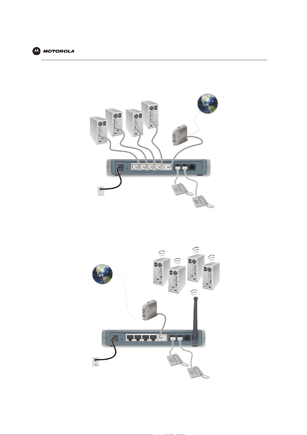
Sample Wired Network for Home or Office (VT2400)
The VT2400 Voice Gateway adds advanced routing features and four Ethernet LAN ports, allowing you to connect
multiple PCs without the need for a stand-alone hub or router. The VT2400 also includes a firewall to help protect
your network against external attacks.
Sample Wireless Network for Home or Office (VT2500)
The VT2500 Wireless Voice Gateway offers all the features of the VT2400 with the added convenience of a built-in
802.11b/g wireless access point for wireless access to broadband services. It eliminates the need for stand-alone
routers, hubs, and access points, providing a single platform for connecting telephones and PCs to a broadband
link.
VT2400/VT2500 Series Voice Gateway User Guide 3
Page 13
Overview Installation Troubleshooting Contact FAQ Specifications Glossary License
Configuration: Basic Advanced TCP/IP Wireless
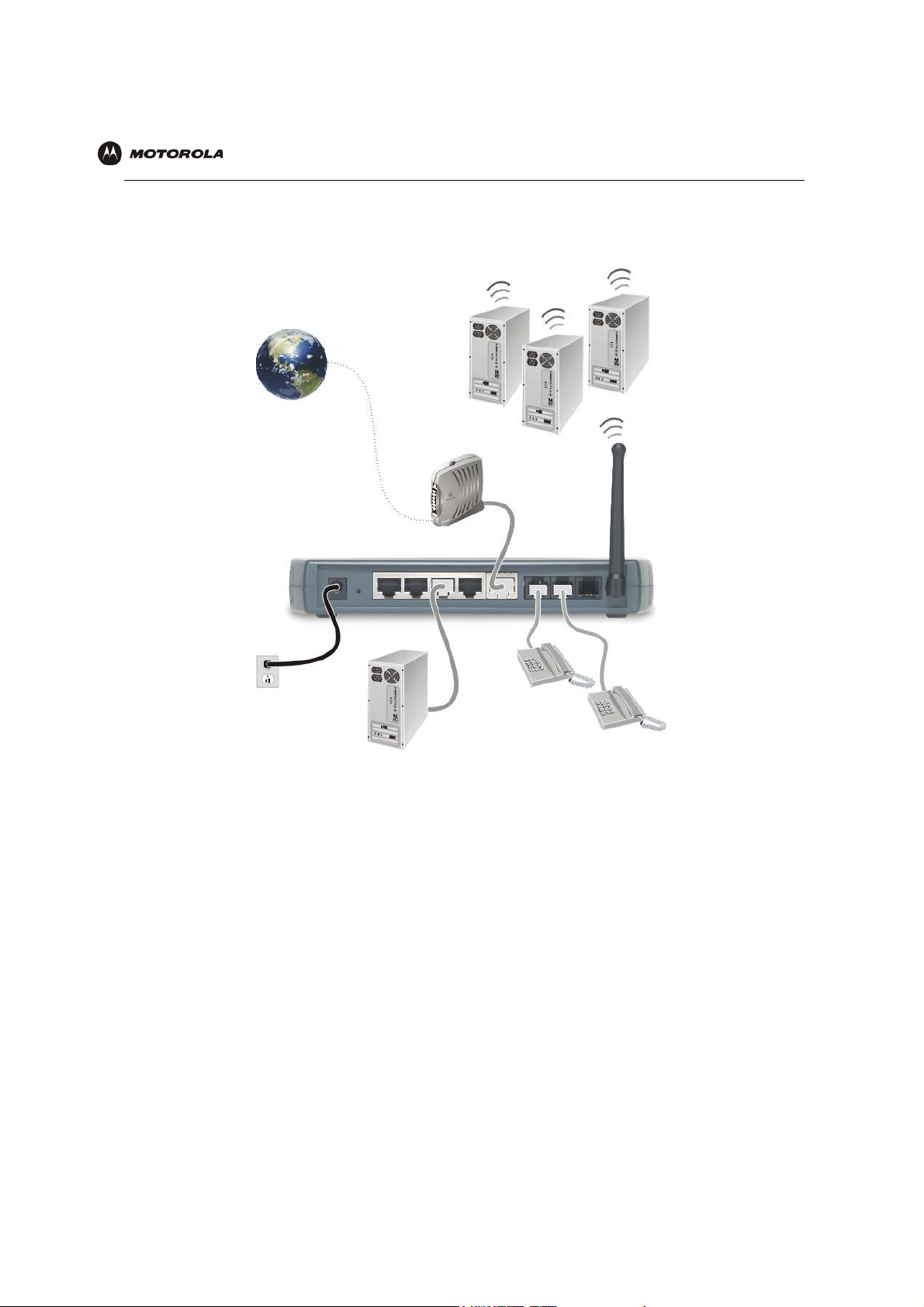
Sample Combination Wired and Wireless Network for Home or Office (VT2500)
The VT2500 Wireless Voice Gateway allows you to set up a combination of wired and wireless PCs and other
devices in your home or office network. Either a cable or DSL modem can be used.
VT2400/VT2500 Series Voice Gateway User Guide 4
Page 14
Overview Installation Troubleshooting Contact FAQ Specifications Glossary License
Configuration: Basic Advanced TCP/IP Wireless
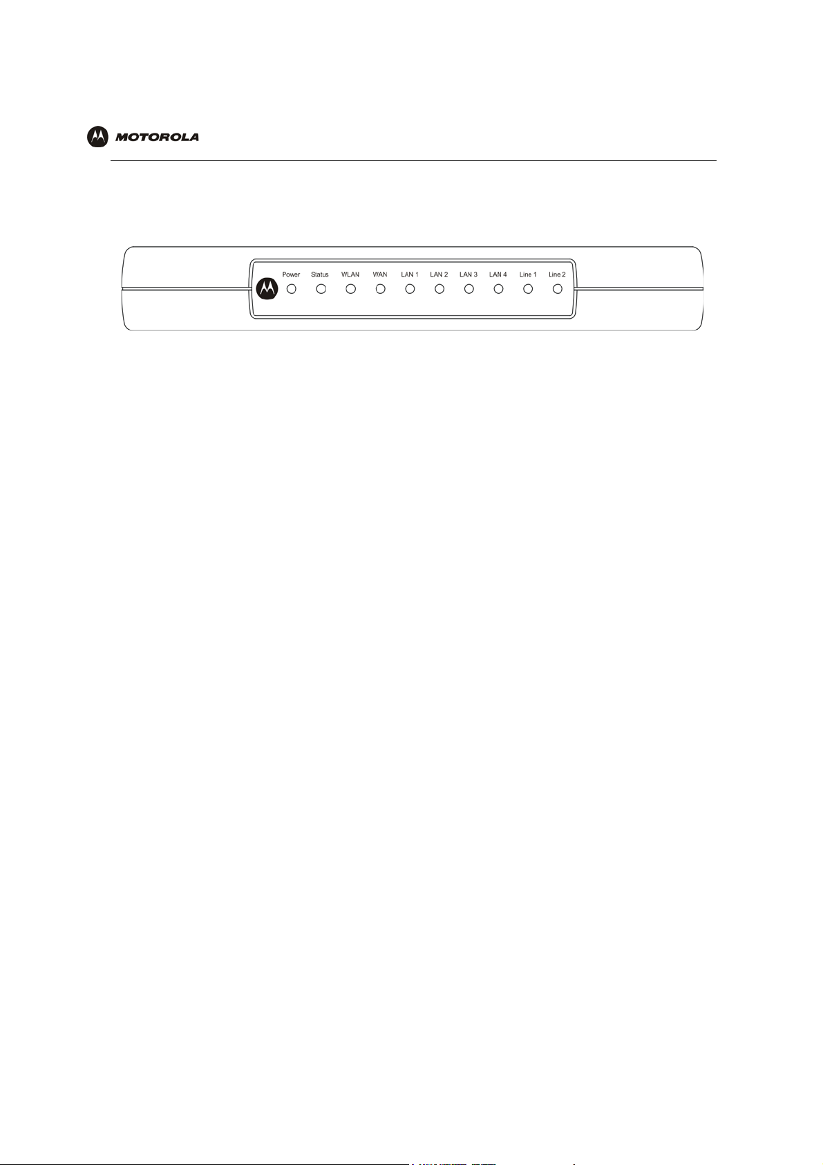
Front Panel
The front panel of your VT2400/VT2500 provides the following LEDs:
Indicator VT2500/VT2400 Function
Power
Status
WLAN (VT2500
only)
WAN
LAN 1
LAN 2
LAN 3
LAN 4
Line 1
Line 2
Solid green if voice gateway is plugged in and operating normally
Series of blinks indicates various voice gateway events (see next table)
Green indicates activity on the wireless LAN
Indicates activity on the WAN (Internet) and link speed *
The devices on a single LAN port or LAN 1 are connected and operational *
The devices on LAN 2 are connected and operational *
The devices on LAN 3 are connected and operational *
The devices on LAN 4 are connected and operational *
Series of blinks indicates status of Line 1 (see next table)
Series of blinks indicates status of Line 2 (see next table)
* Connection speed is indicated as follows: Green if 100Base-T; Amber if 10Base-T
VT2400/VT2500 Series Voice Gateway User Guide 5
Page 15

Overview Installation Troubleshooting Contact FAQ Specifications Glossary License
Configuration: Basic Advanced TCP/IP Wireless
As a troubleshooting aid, the STATUS, LINE 1, and LINE 2 indicators blink as follows during start-up and image
upgrades:
LED Activity Status LED Line 1 or Line 2 LED
None N/A Service is not present on the line
One blink Performing its initial boot sequence The line is off the hook
Two blinks Obtaining its network IP address N/A
a
Three blinks Downloading its configuration profile
from your VoIP provider
Continuous Downloading a firmware upgrade
initiated by your VoIP provider
Solid N/A Successfully registered with your VoIP provider
a. Line 2 is optional
N/A
Attempting to reregister with your VoIP provider
after interruption in service (PSTN failover - see
next table)
The WAN port has a dual color LED to indicate network traffic and connection speed:
LED Activity WAN LED
Solid green If there is a 100Base-T connection without activity
Solid amber If there is a 10Base-T connection without activity
Blinking amber If there is a 10Base-T connection with activity
Caution!
Never unplug your Motorola voice terminal while its light is blinking continuously. Instead, allow the
image upgrade to finish. If you unplug the Motorola voice terminal during an image upgrade, it may
become inoperable.
VT2400/VT2500 Series Voice Gateway User Guide 6
Page 16

Overview Installation Troubleshooting Contact FAQ Specifications Glossary License
Configuration: Basic Advanced TCP/IP Wireless
Rear Panel
The rear panel provides the following connectors:
:
Item Type Connects To
POWER 12 V An adapter that you plug into an AC power outlet
LAN RJ-45 Ethernet connectors for up to four computers/devices
WAN RJ-45 Ethernet connector to your broadband modem, switch, or hub (“WAN” or
“wide area network” refers here to the Internet)
LINE 1 RJ-11 Telephone line one
LINE 2 RJ-11 Telephone line two
PSTN failover RJ-11? Supports a live phone line from the public switched telephone network,
or “land phone” connected to plain old telephone service. If there is a
power failure, phones connected to the voice terminal will still work, but
calls will be routed to the PSTN connection instead of the VoIP
broadband connection.
Reset button ? Reboots the voice terminal if your VoIP service provider has enabled it.
VT2400/VT2500 Series Voice Gateway User Guide 7
Page 17

Overview Installation Troubleshooting Contact FAQ Specifications Glossary License
Configuration: Basic Advanced TCP/IP Wireless
Before You Begin
Before you begin installation, check that you received the following items with your VT2400/VT2500:
Item Description
AC adapter
and line cord
Ethernet
cable
Vertical mounting stand Provides vertical mounting on a flat surface for space
Connects the VT2400/VT2500 to an AC electrical outlet
Connects the WAN port on the VT2400/VT2500 to a
broadband modem (cable or DSL)
Connects the LAN ports on the VT2400/VT2500 to a
computer or other networked device
economy
Requirements and Prerequisites
In addition to the VT2400/VT2500 Voice Gateway, you also need:
• An established Internet connection using a DSL or cable modem (refer to the instructions that came with your
modem)
• Activated voice service from your VoIP provider (see “Signing Up for Service” on page 8)
• One or two touch-tone telephones
• Computers with these minimum requirements:
— Pentium-class processor or faster
— 16 MB of memory
— 10 MB of hard disk space available
— Windows
PC
®
98, Windows® 98 SE, Windows® Me®, Windows®NT, Windows® XP or other Web-enabled
— An Ethernet cable for each computer to be wired to the network (one is provided with the voice gateway).
A wireless adapter installed in each computer to be wireless on the network (refer to the instructions that
came with your wireless adapter)
• Optional:
— You may need additional 10/100Base-T category 3 or better straight-through Ethernet cables with RJ-45
terminators
— Plugging the power adapter into a surge protector is also recommended.
to connect additional Ethernet devices (PCs).
Signing Up for Service
To activate voice service, you must provide the MAC address printed on the bar code label marked MTA MAC ID
on the bottom of the VT2400/VT2500 to your VoIP provider.
Existing Routers
If you have an existing router or wireless access point, you should print out the router or wireless access point
configuration screens so that configuring the VT is made easier. Keep the printed copies for reference later.
VT2400/VT2500 Series Voice Gateway User Guide 8
Page 18

Overview Installation Troubleshooting Contact FAQ Specifications Glossary License
Configuration: Basic Advanced TCP/IP Wireless
Precautions
Caution!
Contact your VoIP provider before connecting your VT2400/VT2500 to your
existing telephone wiring. Connect each LINE port to a telephone only; never to
a traditional telephone service.
Postpone installation until there is no risk of thunderstorm or lightning activity in the area.
To prevent overheating the VT2400/VT2500, do not block the ventilation holes on the top and sides of the unit.
Do not open the VT2400/VT2500. Refer all service to your VoIP provider.
Wipe the
cleaners directly on the unit or use forced air to remove dust.
Any services provided through this equipment:
VT2400/VT2500
with a clean, dry cloth. Never use cleaning fluid or similar
chemicals. Do not spray
• Are not intended to replace or be a substitute for primary line voice services or Plain Old Telephone Service
(POTS)
• Are not meant to provide guaranteed 911 or E911 services or to permit access to 411 directory assistance
services
The service provider, not Motorola, is responsible for the provision of VoIP telephony services through this
equipment. Motorola shall not be liable for, and expressly disclaims, any direct or indirect liabilities, damages,
losses, claims, demands, actions, causes of action, risks or harms arising from or related to the services provided
through this equipment.
IMPORTANT: You cannot make any calls using this VoIP device if your broadband connection is not functioning
properly or if you lose electrical power.
Document Conventions
Before you begin using the VT2400/VT2500, become familiar with the style conventions used in this manual:
Bold type Indicates text that you must type exactly as it appears, fields you are instructed to select
on a graphical user interface (GUI), or a default value
SMALL CAPS Denotes silk screening on the equipment, typically representing front- and rear-panel
controls and input/output (I/O) connections, and LEDs
Italic type Denotes a displayed variable, a variable that you must type, or is used for emphasis
KEY + KEY Key combinations indicating that you hold down the first key and then press the
second key
KEY, KEY Key combinations indicating that you press the first key, release it, and then press the
second key
Courier
font
Indicates text displayed on a graphical user interface (GUI), such as system messages
Related Documentation
The VT2400/VT2500 Series Voice Gateway Quick Start Guide provides instructions for end users to quickly set up
and configure the voice gateway.
VT2400/VT2500 Series Voice Gateway User Guide 9
Page 19

Overview Installation Troubleshooting Contact FAQ Specifications Glossary License
Configuration: Basic Advanced TCP/IP Wireless
Installation
Follow the steps and guidelines in this section to physically set up and position the VT2400/VT2500 voice gateway
on a flat surface or mount it on the wall.
Positioning Your Router for Optimal Wireless Performance (VT2500 only)
Your voice gateway has an embedded wireless router that uses a radio transmission technology defined by the
Institute of Electrical and Electronics Engineers (IEEE) called 802.11 Wireless Fidelity (Wi-Fi). This standard is
subdivided into distinct categories of speed and the frequency spectrum used, designated by the lowercase letter
after the standard.
For example, the router supports both the ‘b’ and ‘g’ specifications. The 802.11b specification transmits data rates
up to 11 Mbps while the 802.11g specification transmits data rates up to 54 Mbps. These are theoretical standards
so performance may vary. The radio waves radiate in a donut-shaped pattern. The waves travel through walls and
floors, but transmission power and distance are affected. The theoretical distance limit is 1,000 feet (305 meters),
but actual throughput and distance varies.
Both standards operate in the 2.4 GHz range, meaning other electrical appliances also might interfere with the
router – televisions, radios, microwave ovens, or 2.4 GHz cordless telephones. Therefore, positioning the voice
gateway where it encounters the least interference helps maintain a better connection.
The following table lists the expected wireless range of the router. This table is only a guide and coverage varies
due to local conditions.
Data Rate Open Area Closed Area
54 Mbps Up to 100 ft (30m) Up to 60 ft (18 m)
11 Mbp s Up to 900 feet (275 m) Up to 160 feet (49 m)
5.5 Mbps Up to 1300 feet (396 m) Up to 200 feet (61 m)
2 or 1 Mbps Up to 1500 feet (457 m) Up to 300 feet (91 m)
To achieve the best wireless performance, review these guidelines before deciding where to place the voice
gateway:
• Placing the voice gateway in the center of your network is the best location because the antenna sends out
the signal in all directions.
• Placing the voice gateway in a higher location, such as on top of a cabinet, helps disperse the signal cleanly,
especially to receiving locations on upper stories.
• If possible, position the voice gateway so there is direct line of sight between the unit and your other home
network devices.
• Avoid placing the voice gateway next to large solid objects like computer cases, monitors, walls, fireplaces,
etc. This helps the signal penetrate more cleanly.
• Other wireless devices such as televisions, radios, microwaves, and 2.4 GHz cordless telephones can
interfere with the signal. Keep these devices away from the voice gateway.
• Mirrors, especially silver-coated, can reduce transmission performance.
VT2400/VT2500 Series Voice Gateway User Guide 10
Page 20
Overview Installation Troubleshooting Contact FAQ Specifications Glossary License
Configuration: Basic Advanced TCP/IP Wireless
Hardware Setup
Hardware setup includes:
• antenna installation (VT2500 only)
• physical placement - horizontal, vertical, or mounted on the wall
• electrical connection - connecting the power cord
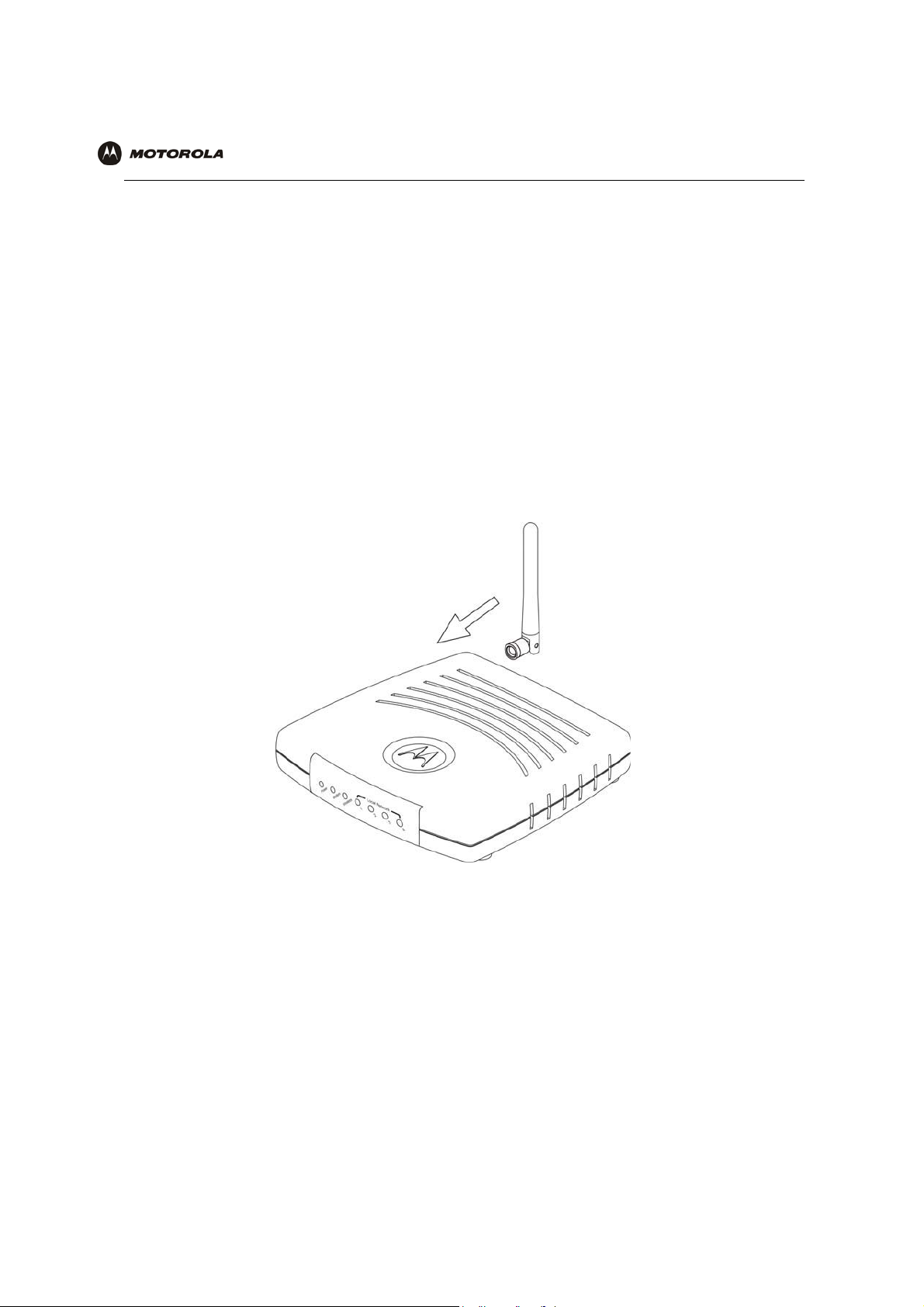
Antenna Installation (VT2500 only)
When shipped, the antenna for the router is not connected to the voice gateway. To attach the antenna to the
voice gateway:
1 Locate the antenna port on the back of the voice gateway (the threaded knob).
2 Screw the antenna connector clockwise onto the threaded knob until firmly seated. Do not over-tighten.
VT2400/VT2500 Series Voice Gateway User Guide 11
Page 21
Overview Installation Troubleshooting Contact FAQ Specifications Glossary License
Configuration: Basic Advanced TCP/IP Wireless
Physical Placement
For desktop use, the voice gateway can be installed either horizontally or vertically. It can also be mounted on a
wall.
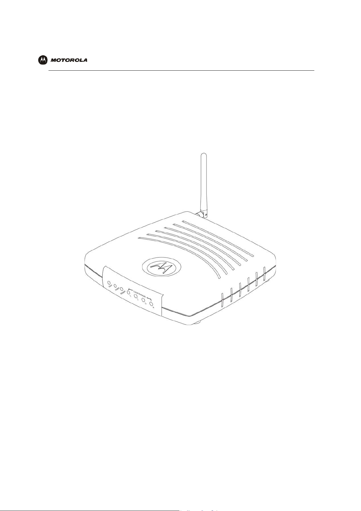
Horizontal Installation
1 Place the voice gateway in the desired location as shown in the figure below.
2 Follow the installation procedures for connecting and configuring the voice gateway to a network.
VT2400/VT2500 Series Voice Gateway User Guide 12
Page 22
Overview Installation Troubleshooting Contact FAQ Specifications Glossary License
Configuration: Basic Advanced TCP/IP Wireless
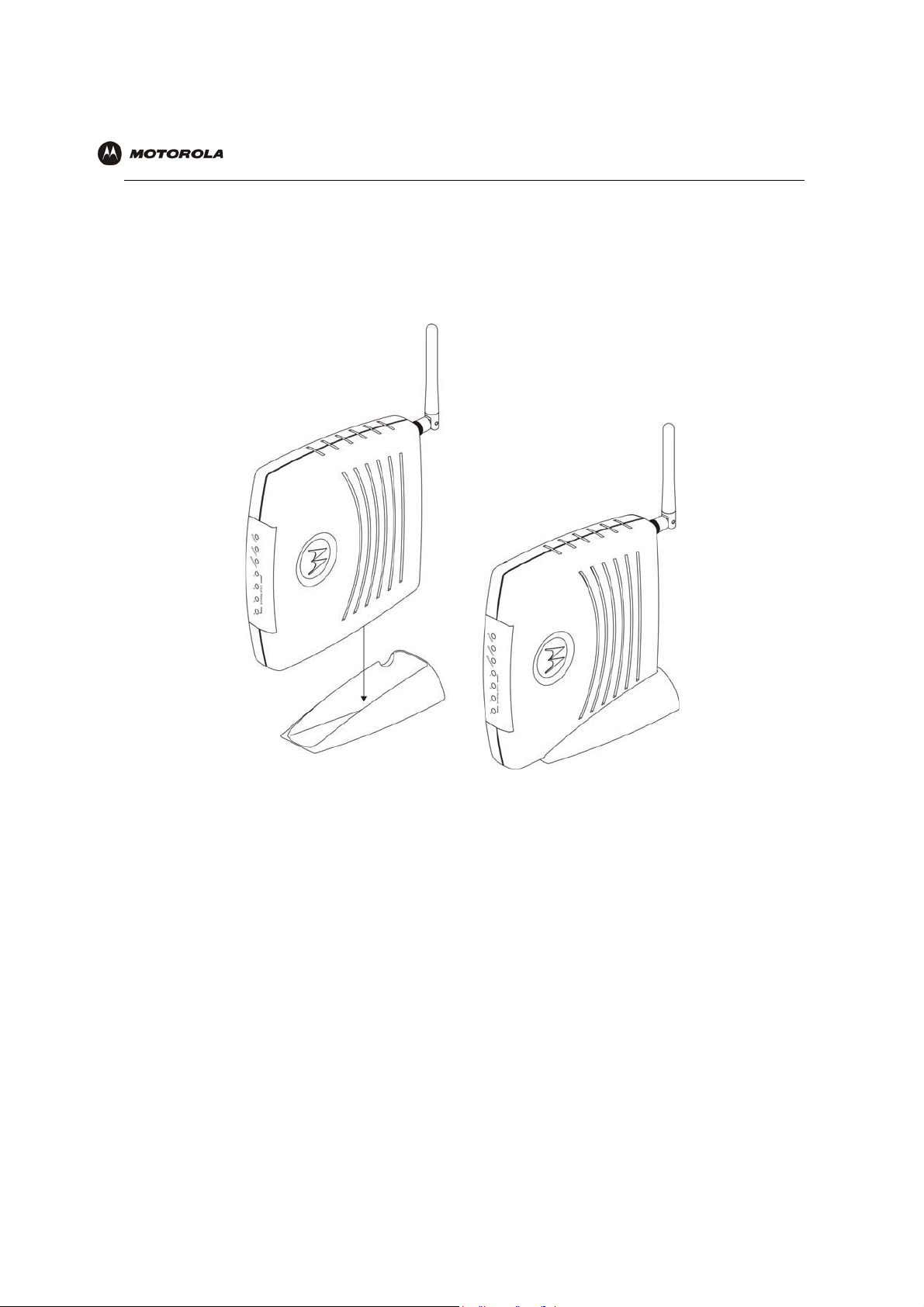
Vertical Installation
1 Insert the router into the supplied base stand. Ensure that the antenna’s location is on top. The voice
gateway’s foot slides snugly into a notch in the base stand to keep it stable.
2 Follow the installation procedures for connecting and configuring the voice gateway to a network.
Wall Mount Installation
If you mount the VT2400/VT2500 on the wall, you must:
• Position the VT2400/VT2500 as specified by the local or national codes governing residential or business
communications services.
• Follow all local standards for installing a network interface router/network interface device (NIU/NID).
If possible, mount the VT2400/VT2500 to concrete, masonry, a wooden stud, or other solid wall material. Use
anchors when necessary, such as when you must mount the voice gateway on drywall.
To mount the VT2400/VT2500 on the wall:
1 Print the Wall Mounting Template diagram in the Specifications section of this manual.
The illustration shows the two keyholes with the plus sign that indicates the center where the screws must be
located (7.047 inches apart). The drawing provides the exact dimensions required to mount the
VT2400/VT2500 on a wall.
VT2400/VT2500 Series Voice Gateway User Guide 13
Page 23
Overview Installation Troubleshooting Contact FAQ Specifications Glossary License
Bef
illi
Configuration: Basic Advanced TCP/IP Wireless
To print the Wall Mounting Template, click the Print icon or choose Print from the File menu.
2
3 In the Pages field, enter the page number in this manual on which the Wall Mounting Template appears.
4 Click OK.
5 Measure the printed template with a ruler to ensure that it is the same size as the template drawing indicates
(7.047 inches).
6 Use a center punch to mark the center of the holes on the wall.
7 On the wall, locate the marks for the mounting holes you just made.
Warning!
ore dr
ng holes, check thestructure for potential damage towater, gas, or electric lines.
8 Drill the holes to a depth of at least 3.8 cm (1½ inches).
9 If necessary, seat an anchor in each hole. Use M5 x 38 mm (#10-16 x 11/2 inch) screws with a flat underside
and maximum screw head diameter of 10.5 mm to mount the voice gateway.
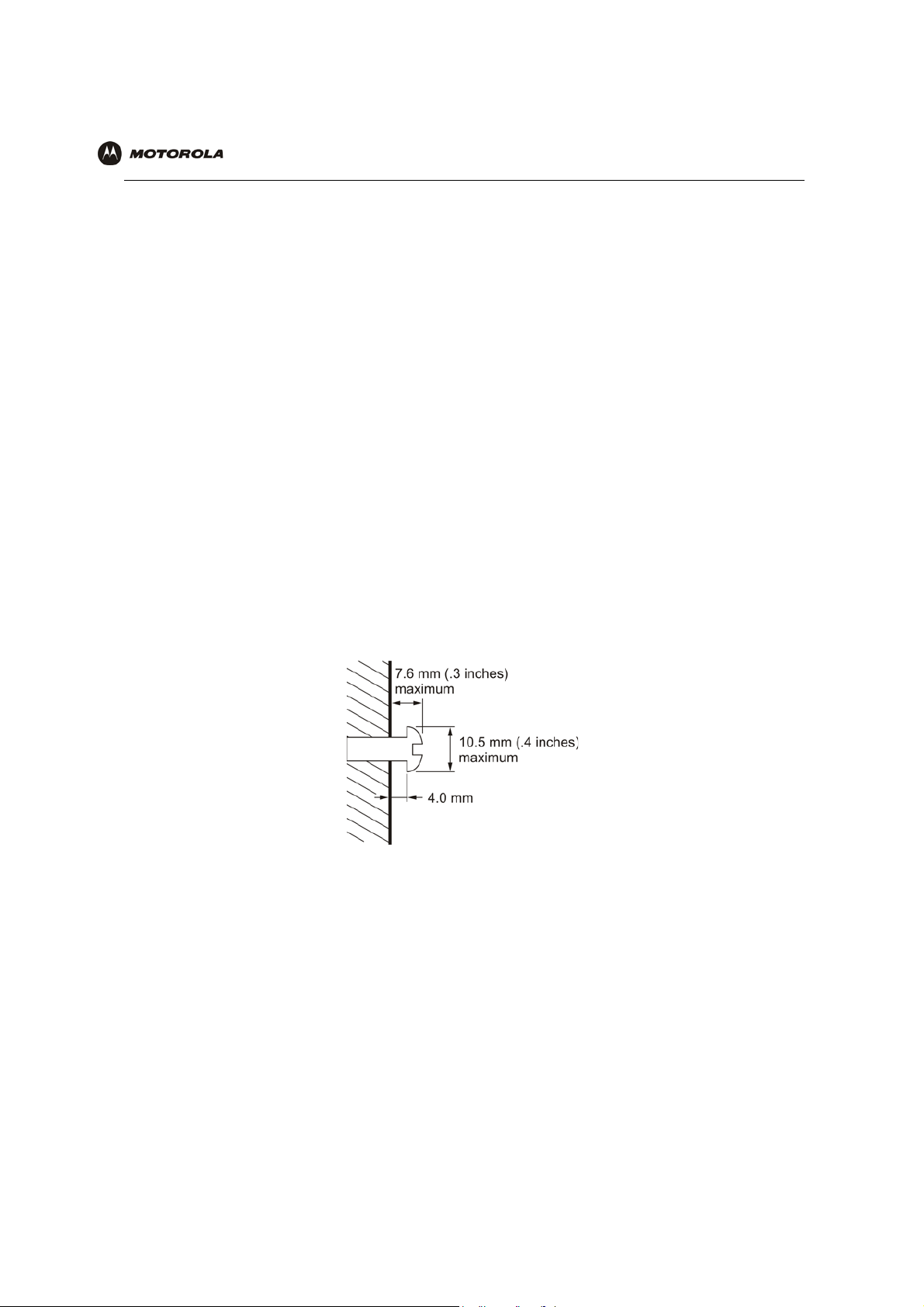
10 Using a screwdriver, turn each screw until part of it protrudes from the wall, as shown:
• –There must be 4.0 mm (.16 inches) between the wall and the underside of the screw head.
• –The maximum distance from the wall to the top of the screw head is 7.6 mm (.3 in).
11 Remove the two plastic feet (nearest to the LED panel) from the bottom of the router to uncover the keyholes.
12 Place the voice gateway so the keyholes are above the mounting screws.
13 Slide the voice gateway down until it stops against the top of the keyhole opening.
14 Follow the installation procedures for connecting and configuring the voice gateway.
Electrical Connection
Your voice gateway does not have an On/Off power switch and therefore is only powered on by plugging in the
power adapter.
VT2400/VT2500 Series Voice Gateway User Guide 14
Page 24
Overview Installation Troubleshooting Contact FAQ Specifications Glossary License
Configuration: Basic Advanced TCP/IP Wireless
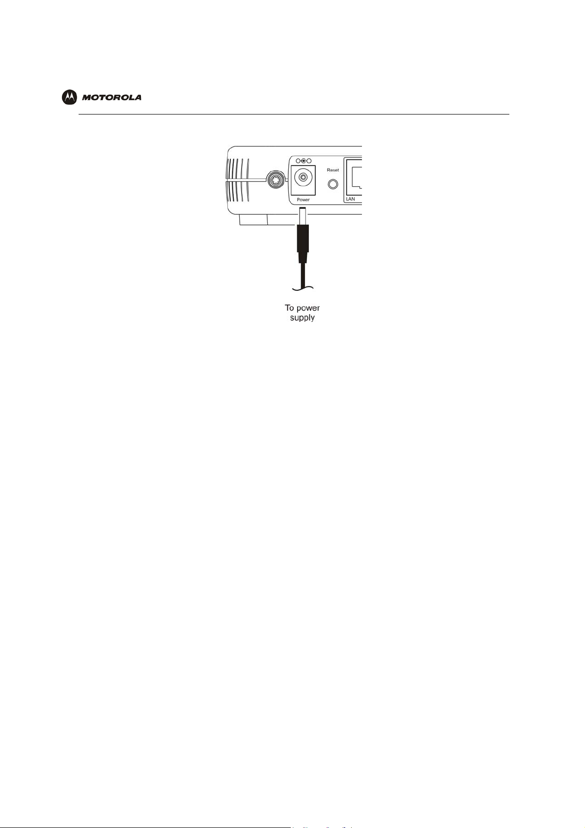
Connect the power adapter to the voice gateway Power port, found on the back of the unit.
1
2 Plug the power adapter into a grounded and surge-protected power outlet. The Power LED on the front panel
lights green when connected properly.
VT2400/VT2500 Series Voice Gateway User Guide 15
Page 25
Overview Installation Troubleshooting Contact FAQ Specifications Glossary License
Configuration: Basic Advanced TCP/IP Wireless
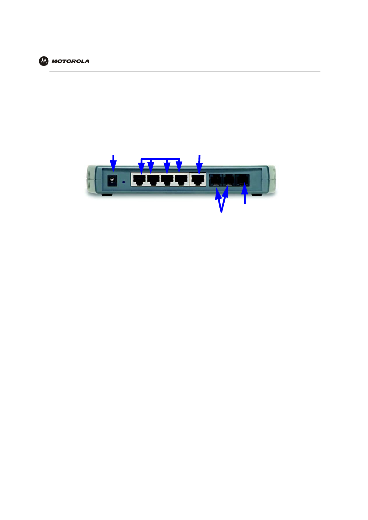
Connecting the VT2400/VT2500 to a Network
If you are setting up a wireless network only, the computers in the following diagrams will not use Ethernet cables
to connect them.
If you have an existing modem, follow the procedure in “Adding the VT2500/VT2400 to an Existing Network”. If
you are setting up a network for the first time (adding devices to a single PC setup), see “Setting Up a New
Network” and then go to “Configuring the Voice Gateway to the Modem” on page 17.
Power connector
LAN (Ethernet) WAN port
ports
Phone Line 1, 2
PSTN Failover
Setting Up a New Network
Follow these instructions if you have a single PC connected directly to the modem, or no Internet connection until
now.
1 Be sure the modem and the PCs are turned off and the VT2400/VT2500 is unplugged.
2 If you only have a single PC connected, disconnect the Ethernet cable from the PC to the modem (on the
modem end only) and connect it to a LAN port on the VT2400/VT2500.
3 Connect up to three additional PCs using Ethernet cables to the VT2400/VT2500. Connect one end of each
Ethernet cable to a PC and the other end to a LAN port on the VT2400/VT2500.
4 Connect one end of an Ethernet cable (RJ-45) to the modem, and connect the other end to the WAN port on
the VT2400/VT2500.
5 Connect up to two existing land phone lines (after you disconnect them from the wall jacks) and connect them
to the LINE 1 and LINE 2 ports on the VT2400/VT2500.
VT2400/VT2500 Series Voice Gateway User Guide 16
Page 26

Overview Installation Troubleshooting Contact FAQ Specifications Glossary License
Configuration: Basic Advanced TCP/IP Wireless
Adding the VT2500/VT2400 to an Existing Network
You may have a combination of wired and wireless devices on your existing network. Follow these steps to
connect only those PCs to be wired. These instructions will also help you modify an existing network that uses a
separate router or wireless access point.
To connect PCs using an Ethernet cable:
1 Be sure the existing modem, router, and PCs are turned off and the VT2400/VT2500 is unplugged.
2 Disconnect the Ethernet cable (RJ-45) that connects the modem to the router (on the router/WAP end only)
and then connect it to the WAN port on the VT2400/VT2500.
3 Disconnect the Ethernet cables that connect the PCs to the router (on the router/WAP end only) and connect
them to the LAN ports on the VT2400/VT2500.
4 Connect up to two existing land phone lines (after you disconnect them from the wall jacks) and connect them
to the LINE 1 and LINE 2 ports on the VT2400/VT2500.
Configuring the Voice Gateway to the Modem
Most high-speed Internet connections use a cable modem or a DSL modem. The cable modem is connected to
your cable television company coax cable. The DSL modem is connected to a telephone company phone line.
Determine which modem you are using and gather the information on the worksheet below. You will use this
information in the next section, Basic Configuration, before you check the voice gateway’s connection to your VoIP
provider.
Cable Modem
If you have a cable modem, you will need to contact your cable Internet provider for all of the information in the
Cable Modem column on the worksheet. Or, you can refer to the cable modem configuration pages that you
printed out before setting up the network, as recommended in Section X.
DSL Modem
If you have a DSL modem, you will need to contact your telephone Internet provider for all of the information in the
DSL Modem column on the worksheet. Or, you can refer to the DSL modem configuration pages that you printed
out before setting up the network, as recommended in Section X.
VT2400/VT2500 Series Voice Gateway User Guide 17
Page 27

Overview Installation Troubleshooting Contact FAQ Specifications Glossary License
Configuration: Basic Advanced TCP/IP Wireless
After you fill in the worksheet, perform the steps that follow the worksheet.
Modem Worksheet
Cable Modem (cable company) DSL Modem (phone company)
Service Name _______________________________ ________________________
You r U ser Na m e _______________________________ ________________________
You r P asswo r d _______________________________ ________________________
DHCP Is the IP address obtained dynamically? PPPoE
Yes No need to fill in the rest of this section
of the work sheet. Proceed to DNS
Server IP Addresses.
N/A
No What are the values for the Static IP
Address, Subnet Mask, and Default
Gateway:
Static IP
Address
Subnet Mask _______________________________ N/A
WAN Default
Gateway
DNS Server IP
Addresses:
(up to 3)
_______________________________ N/A
_______________________________ N/A
What are the DNS server IP addresses? (Sometimes DHCP does not assign them
dynamically, so be sure to ask your cable provider, even if you answered Yes to
DHCP above.) PPPoE requires DNS Server IP Addresses as well.
1) _____________________________
2) _____________________________
3) _____________________________
N/A
1) _____________________________
2) _____________________________
3) _____________________________
Checking the Network Connections
1 Turn on the DSL or cable modem, following the instructions provided with the modem. Wait about two
minutes for it to start up.
2 Plug the AC power adapter to the POWER connector on the VT2400/VT2500 and the other end to an
electrical outlet. This turns on the VT2400/VT2500 Voice Gateway. You do not need to unplug it when it is not
in use.
Wait about two minutes for the VT2400/VT2500 to start up. The Power light performs a series of blinks, as
described in “Front Panel” on page 5.
3 After the Power light on the VT2400/VT2500 is solid green, turn on your computer. If the Internet connection
does not work as it did before you installed the VT2400/VT2500, refer to “Troubleshooting” on page 116.
4 Before you can verify that the phone is working, you need to complete several basic configuration
procedures. Proceed to “Basic Configuration” on page 19.
VT2400/VT2500 Series Voice Gateway User Guide 18
Page 28
Overview Installation Troubleshooting Contact FAQ Specifications Glossary License
Configuration: Basic Advanced TCP/IP Wireless
Basic Configuration
This section provides initial procedures required for configuring the network attached to the voice gateway. These
include:
• Starting the VT2400/VT2500 Voice Gateway Setup Program
• Changing the Default Password
• Setting Up Minimum Security Network Options, such as selecting the firewall policy, enabling the firewall,
disabling the wireless option (if you are setting up a wired network only), or enabling wireless security (if
setting up a LAN with one or more wireless clients)
• Gaming Configuration Guidelines
• Help
• Rebooting
• Logging Out
For more advanced configuration information, see “Advanced Configuration” on page 31.
For normal operation, you do not need to change most default settings.
Caution!
To prevent unauthorized configuration, change the default password immediately when you first
configure the VT2400/VT2500. See “Changing the Default Password”.
Firewalls are not foolproof. Choose the most secure firewall policy you can. See “Setting Up
Minimum Security Network Options”.
If you are using a wired LAN only and have no wireless clients, be sure you disable the wireless
interface by turning off Enable Wireless Interface on the Wireless > NETWORK.
For a wireless LAN only, be sure you follow the instructions in “Setting Up Your Wireless LAN
(WLAN)”.
VT2400/VT2500 Series Voice Gateway User Guide 19
Page 29
Overview Installation Troubleshooting Contact FAQ Specifications Glossary License
Configuration: Basic Advanced TCP/IP Wireless
Starting the VT2400/VT2500 Voice Gateway Setup Program
On a computer wired to the VT2400/VT2500, open a Web browser.
Caution:
Run the voice gateway configuration setup program only from a PC attached to the voice
gateway with an Ethernet cable. Do not use a wireless device to configure the network.
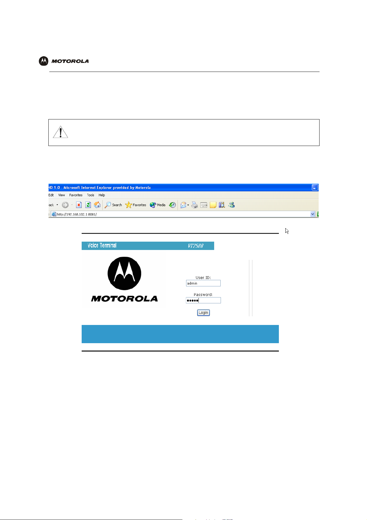
1 On a computer wired to the VT2400/VT2500, open a Web browser, such as Internet Explorer or Netscape.
2 In the Address or Location field, type http://192.168.102.1 or http://192.168.0.1 and press ENTER to display
the Log In window:
3 In the User ID field, type the user name. The default is admin (this field is case sensitive).
4 In the Password field, type the password. The default is motorola (this field is case sensitive).
VT2400/VT2500 Series Voice Gateway User Guide 20
Page 30
Overview Installation Troubleshooting Contact FAQ Specifications Glossary License
Configuration: Basic Advanced TCP/IP Wireless
Click Log In to display the VT2400/VT2500 user configuration setup screens:
5
If you have difficulty starting the VT2400/VT2500 setup program, see “Troubleshooting” for information.
After you edit the field and click Apply for some settings, you are required to reboot the VT2400/VT2500 for
the changes to take effect. Rebooting takes 10 to 15 seconds. After rebooting, you must log in again.
VT2400/VT2500 Series Voice Gateway User Guide 21
Page 31

Overview Installation Troubleshooting Contact FAQ Specifications Glossary License
Configuration: Basic Advanced TCP/IP Wireless
Changing the Default Password
Caution!
To prevent unauthorized configuration, change the default password immediately when you first
configure the VT2400/VT2500 Voice Gateway.
To change the default password after you log in:
1 On the Gateway > STATUS page, click Launch Getting Started Wizard to display the Change Admin
Password page:
2 In the Old Password field, type the old password. The default password is motorola (this field is case
sensitive).
3 In the New Password field, type the new password.
4 In the Retype Password field, type the new password again.
5 Click Apply to make your changes.
VT2400/VT2500 Series Voice Gateway User Guide 22
Page 32

Overview Installation Troubleshooting Contact FAQ Specifications Glossary License
Configuration: Basic Advanced TCP/IP Wireless
Setting Up Minimum Security Network Options
For basic operation of your network, these tasks must be completed:
• Selecting the firewall policy and enabling the firewall
• Disabling the wireless option (if you are setting up a wired network only); or
• Enabling wireless security (if setting up a LAN with one or more wireless devices
Setting the Firewall Policy and Enabling the Firewall
The VT2400/VT2500 firewall protects your LAN from attacks and other intrusions from the Internet. This section
describes using the Policy > POLICY — config page to choose one of the predefined firewall policies provided
with the voice gateway.
Caution!
Firewalls are not foolproof. Choose the most secure firewall policy possible. To enable easy network
setup, the default firewall policy is None, which provides no security.
The predefined policies provide outbound Internet access for computers on the VT2400/VT2500 LAN. The voice
gateway firewall uses stateful inspection to allow inbound responses when there already is an outbound session
running corresponding to the data flow. For example, if you use a Web browser, outbound HTTP connections are
permitted on port 80. Inbound responses from the Internet are allowed because an outbound session is
established.
To set up a custom firewall, see Firewall > FIREWALL — basic in Advanced Configuration.
VT2400/VT2500 Series Voice Gateway User Guide 23
Page 33

Overview Installation Troubleshooting Contact FAQ Specifications Glossary License
Configuration: Basic Advanced TCP/IP Wireless
To select a predefined policy for all data processed by the VT2400/VT2500 firewall:
1 After you log in, click Firewall on the main menu then click Firewall. The Firewall > FIREWALL — basic page
appears.
2 Click the most secure firewall policy possible.
High The safest firewall policy template, that provides the highest security. We recommend this setting.
Medium A firewall policy template that provides a common configuration having modest risk.
Low A firewall policy template that provides minimum security, with a higher risk of intrusions.
Custom You may need to create your own custom firewall policy. Do not create a custom policy unless you have
the necessary expertise and the need to do so.
3 Click Apply to make your changes.
After you edit the field and click Apply for some settings, you are required to reboot the VT2400/VT2500 for
the changes to take effect. Rebooting takes 10 to 15 seconds. After rebooting, you must log in again.
For more advanced security, you can:
• View the rules for the High, Medium, and Low predefined policy templates or create a custom policy on the
Firewall > FIREWALL — advanced page.
• View the firewall logs on the Firewall > LOG page.
• Configure the VT2500 firewall to allow inbound packets without first establishing an outbound session. You
will also need to configure a port forwarding entry on the Gateway > PORT FORWARDING — config page or
a DMZ client on the Gateway > LAN – static leases page.
VT2400/VT2500 Series Voice Gateway User Guide 24
Page 34

Overview Installation Troubleshooting Contact FAQ Specifications Glossary License
Configuration: Basic Advanced TCP/IP Wireless
For information about these options refer to Advanced Configuration. For more information about how the firewall
can affect gaming, see Gaming Configuration Guidelines.
Disabling the Wireless Option
If you do not plan to have any wireless devices in your network, make sure the Enable Wireless Interface check
box is not selected on the Wireless > NETWORK page.
Enabling Wireless Security for Wireless Devices
Follow this procedure if you plan to have wireless devices in your network.
1 On the Wireless > NETWORK page, select the Enable Wireless Interface check box.
2 Change the ESSID name. Type up to 32 alphanumeric case-sensitive characters.
Caution!
The default ESSID name is Motorola. It is recommended that you change the default immediately upon
setting up your WLAN.
3 Click Save Changes.
4 On the Wireless > SECURITY > advanced page, select the ESSID Broadcast check box.
5 Click Apply.
6 Go to Setting Up Your Wireless LAN (WLAN) to complete all other required procedures for setting up your
WLAN.
VT2400/VT2500 Series Voice Gateway User Guide 25
Page 35

Overview Installation Troubleshooting Contact FAQ Specifications Glossary License
Configuration: Basic Advanced TCP/IP Wireless
Gaming Configuration Guidelines
The following sections provide information about configuring the voice gateway firewall and a DMZ for gaming.
Configuring the Firewall for Gaming
By default, the VT2500 firewall is disabled. If you enable the firewall, as recommended, refer to the game’s
documentation to ensure that the necessary ports are open for use by that game.
The predefined VT2400/VT2500 firewall policies affect Xbox Live
Low Xbox Live data can pass through the firewall. No user action is required.
Medium or high To enable Xbox Live traffic to pass, you must configure:
• Choose Firewall > FIREWALL — advanced to create your own custom firewall
• Enter UDP 88:88 and UDP/TCP 3074:3074 on the ...........?
Configuring Port Triggers
Because the voice gateway has predefined port triggers for games using any of the following applications, no user
action is required to enable them:
• DirectX 7 and DirectX 8
TM
as follows:
• MSN Games by Zone.com
• Battle.net
For a list of games supported by Battle.net, visit http://www.battle.net.
You may need to create custom port triggers to enable other games to operate properly. If you set custom port
triggers and enable the firewall, you must customize the firewall to allow traffic through those ports. To create
custom port triggers, use the Gateway > PORT TRIGGERS - custom page.
VT2400/VT2500 Series Voice Gateway User Guide 26
Page 36

Overview Installation Troubleshooting Contact FAQ Specifications Glossary License
Configuration: Basic Advanced TCP/IP Wireless
Configuring a Gaming DMZ Host
Caution!
The gaming DMZ host is not protected by the firewall. It is open to communication or hacking from any
computer on the Internet. Consider carefully before configuring a device to be in the DMZ.
Some games and game devices require one of these:
• The use of random ports
• The forwarding of unsolicited traffic
For example, to connect a PlayStation
the ports required vary from game to game. For these games, we recommend configuring the gaming computer or
device as a gaming DMZ device.
To configure a gaming DMZ device, on the Gateway > LAN – static leases page:
1 Reserve a private IP address for the computer or game device MAC address.
2 Designate the device as a DMZ device.
®
2 for PS2® online gaming, designate it as the gaming DMZ host because
You can reserve IP addresses for multiple devices, but only one device can be designated as the gaming DMZ at
a time.
VT2400/VT2500 Series Voice Gateway User Guide 27
Page 37

Overview Installation Troubleshooting Contact FAQ Specifications Glossary License
Configuration: Basic Advanced TCP/IP Wireless
Help
Use this page to obtain Help screens when using the VT2400/VT2500 graphical user interface. For example....
Help page fields
Field or Button Description
HELP Generates a help window that contains a description and other information.
Note to reviewers: is there a search optionon the Help button?
VT2400/VT2500 Series Voice Gateway User Guide 28
Page 38

Overview Installation Troubleshooting Contact FAQ Specifications Glossary License
Configuration: Basic Advanced TCP/IP Wireless
Rebooting
When you click Reboot, this message appears:
Click OK to reboot the VT2400/VT2500 voice terminal. The current configuration (or changes you just made using
the Apply buttons) will be kept.
Click Cancel to cancel the reboot.
VT2400/VT2500 Series Voice Gateway User Guide 29
Page 39

Overview Installation Troubleshooting Contact FAQ Specifications Glossary License
Configuration: Basic Advanced TCP/IP Wireless
Logging Out
When you click Log Out, the VT2400/VT2500 Setup Program log in screen appears.
VT2400/VT2500 Series Voice Gateway User Guide 30
Page 40

Overview Installation Troubleshooting Contact FAQ Specifications Glossary License
Configuration: Basic Advanced TCP/IP Wireless
Advanced Configuration
This section describes how to use the configuration pages in the VT2400/VT2500 Setup Program for configuring
your local and wide area networks. You will need to refer to the Configuration Worksheet you filled out in
Installation to successfully configure your network.
• Gateway > STATUS
• Gateway > WAN — DHCP Client
• Gateway > WAN — PPPoE Client
• Gateway > WAN — Static
• Gateway > LAN — nat config
• Gateway > LAN — dhcp server config
• Gateway > LAN — dhcp leases
• Gateway > LAN – static leases
• Gateway > PORT FORWARDING — status
• Gateway > PORT FORWARDING — config
• Gateway > PORT TRIGGERS - predefined
• Gateway > PORT TRIGGERS - custom
• Gateway > DNS
• Gateway > LOG
• System > CONTROL
• System > CONFIGURATION — backup
• System > CONFIGURATION — restore
• System > CONFIGURATION — reset
• System > LOG
• Firewall > FIREWALL — basic
• Firewall > FIREWALL — advanced
• Firewall > CONTENT FILTER — status
• Firewall > CONTENT FILTER — config
• Firewall > SCHEDULES — status
• Firewall > SCHEDULES — config
• Firewall > LOG
• Voice > STATUS
• Voice > SERVICE
• Users > USERS — status
• Users > USERS — config
• Users > USER GROUPS
• Users > LOG
• Wireless > STATUS
• Wireless > NETWORK
• Wireless > SECURITY – basic
• Wireless > SECURITY – advanced
• Wireless > STATISTICS
After you edit the field and click Apply for some settings, you are required to reboot the VT2400/VT2500 for
the changes to take effect. Rebooting takes 10 to 15 seconds. After rebooting, you must log in again.
VT2400/VT2500 Series Voice Gateway User Guide 31
Page 41

Overview Installation Troubleshooting Contact FAQ Specifications Glossary License
Configuration: Basic Advanced TCP/IP Wireless
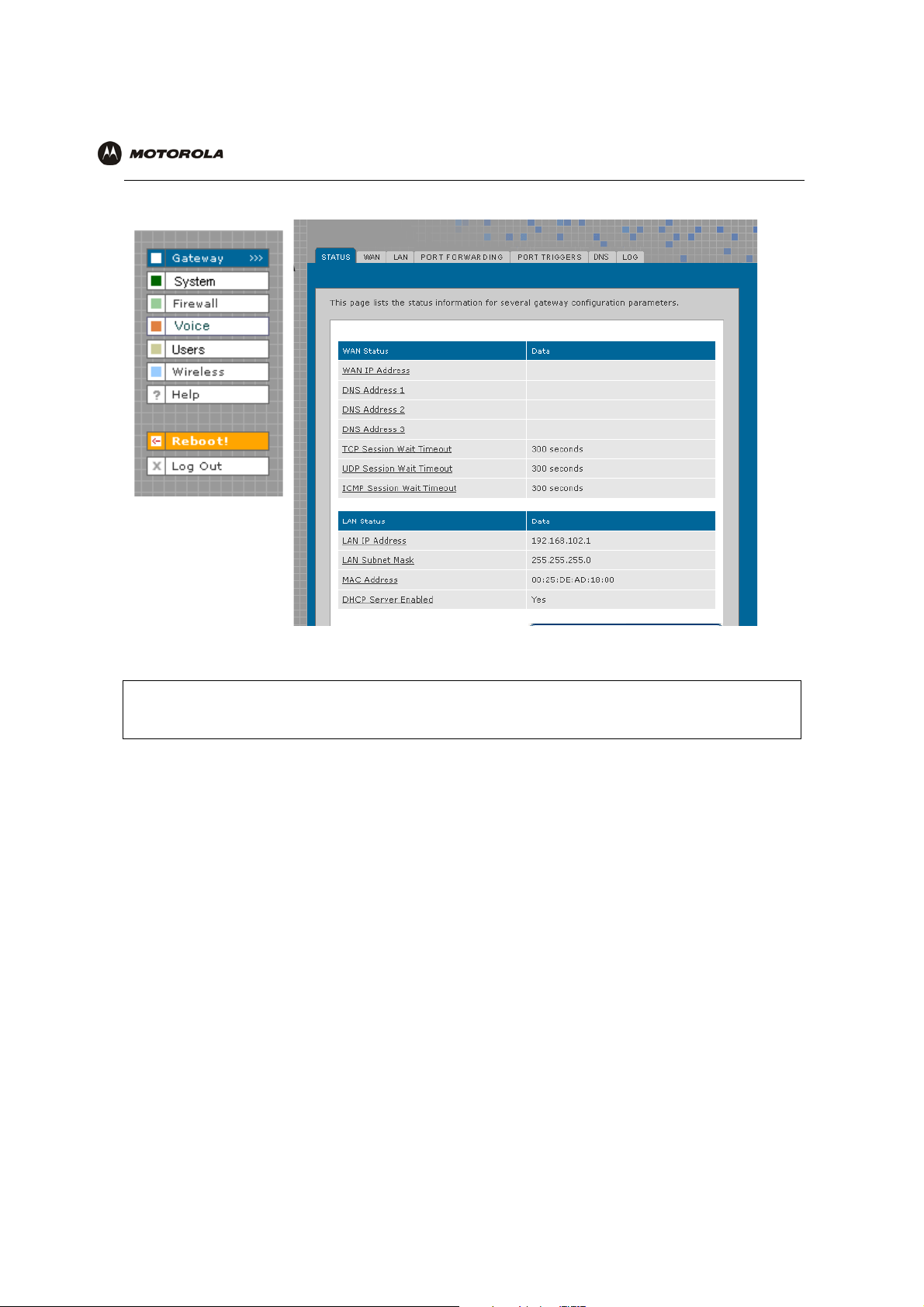
Using the Getting Started Wizard
When you log in to the VT2400/VT2500 setup program, the first screen that appears (Gateway > STATUS)
provides a configuration wizard to help you through the configuration screens. By selecting Launch Getting
Started Wizard on the Gateway > STATUS page, you can access a subset of the configuration screens in
succession. To use the online help, click any field that is underlined on any wizard screen to obtain a Help window,
which provides information to help you configure that particular field.
Voice gateway setup program tabs
Click to obtain Help window
Help window Close button
In the example shown, if you click Enable Manual MTU
Transmission Unit (MTU). To close the Help screen, simply click the close button in the upper right corner.
When you finish the current screen, click the next tab at the top of the graphical user interface to continue
configuring the voice gateway network. In the example shown, you would click LAN after entering all the
necessary information on the WAN pages.
Refer to the corresponding configuration pages in this section for more help when configuring the network using
the wizard.
VT2400/VT2500 Series Voice Gateway User Guide 32
, the Help window displays information about Maximum
Page 42

Overview Installation Troubleshooting Contact FAQ Specifications Glossary License
Configuration: Basic Advanced TCP/IP Wireless
Gateway > STATUS
This page displays the status information for several gateway configuration parameters:
To view a definition of any field on the Status page, click the underlined field
displays the definition.
You may want to select the Launch Getting Started Wizard, which takes you through the minimum screens you
need to verify for any voice gateway network. Refer to “Using the Getting Started Wizard” for more information.
VT2400/VT2500 Series Voice Gateway User Guide 33
. A Help screen appears that
Page 43

Overview Installation Troubleshooting Contact FAQ Specifications Glossary License
Configuration: Basic Advanced TCP/IP Wireless
Gateway > WAN — DHCP Client
Use this page to configure the external (public) wide area network (WAN) interface for an IP Allocation Method of
DHCP Client. Refer to your Modem Worksheet in “Basic Configuration” to determine which type of IP allocation
method you must configure.
Gateway > WAN — DHCP Client page fields
Field Description
IP ALLOCATION METHOD:
DHCP Client (default) Use this page if you have a cable Internet provider that uses dynamic IP addressing, which
automatically obtains the public IP address, subnet mask, domain name, and DNS
server(s). DHCP Client is the default IP allocation method.
CONFIGURATION
Request Lease Click this button to obtain a DHCP leased IP address. Once the lease is acquired, the
assigned settings are displayed. Up to 64 IP addresses can be leased.
Enable IDS Enables the intrusion detection system (IDS) which inspects all inbound and outbound
network activity.
Enable Manual MTU Defines the maximum size of the packets sent from your computer to the network. Enter
1500 for an Ethernet LAN (how about for wireless- leave blank?)
Apply (button) Click Apply to save your changes.
VT2400/VT2500 Series Voice Gateway User Guide 34
Page 44

Overview Installation Troubleshooting Contact FAQ Specifications Glossary License
Configuration: Basic Advanced TCP/IP Wireless
Gateway > WAN — PPPoE Client
Use this page to configure the external (public) wide area network (WAN) interface with an IP Allocation Method of
PPPoE Client. Refer to your Modem Worksheet in “Basic Configuration” to determine which type of IP allocation
method you must configure.
:
Gateway > WAN — PPPoE Client page fields
Field Description
IP ALLOCATION METHOD:
PPPoE Client Use this page if you have a DSL service provider.
CONFIGURATION
Connect (button) Click this button to obtain a DHCP leased IP address. Once the lease is acquired, the
assigned settings are displayed.
User Name Type the user name you selected when you set up your user name in the basic
configuration procedures.
Password Type the password you selected when you set up your password in the basic configuration
procedures.
Disconnect After From the list, select the amount of time before being disconnected from the Internet after a
period of inactivity.
Note: The default for auto-reconnect is enabled. When auto-reconnect is enabled, the
disconnect timer is automatically disabled. (Where is auto reconnect configured?)
Enable IDS Enables the intrusion detection system (IDS), which inspects all inbound and outbound
network activity.
Enable Manual MTU Defines the maximum transmission unit (size of packets) sent from your computer to the
network. Enter 1500 for an Ethernet LAN. (How about for wireless- leave blank?)
Apply (button) Click Apply to save your changes.
VT2400/VT2500 Series Voice Gateway User Guide 35
Page 45

Overview Installation Troubleshooting Contact FAQ Specifications Glossary License
Configuration: Basic Advanced TCP/IP Wireless
Gateway > WAN — Static
Use this page to configure the external (public) wide area network (WAN) interface. The default is DHCP Client.
Refer to your Modem Worksheet in “Basic Configuration” to determine which type of IP allocation method you
must configure.
Gateway > WAN — Static page fields
Field Description
IP ALLOCATION METHOD:
Static Use this page if you answered No on the worksheet to “Is the IP address obtained
dynamically?”
CONFIGURATION
IP Address Type the static IP address provided by the service provider in dotted-decimal format. The
default is None. Example: 192.168.102.150
Subnet Mask Type the subnet mask associated with the static IP address in dotted-decimal format. The
default is None.
Gateway Type the default gateway IP address on the WAN for the
dotted-decimal format.
Enable IDS Enables the intrusion detection system (IDS), which inspects all inbound and outbound
network activity.
Enable Manual MTU Defines the maximum size of the packets sent from your computer to the network. Enter
1500 for an Ethernet LAN (How about for wireless?).
Apply (button) Click Apply to save your changes.
VT2400/VT2500 in
VT2400/VT2500 Series Voice Gateway User Guide 36
Page 46

Overview Installation Troubleshooting Contact FAQ Specifications Glossary License
Configuration: Basic Advanced TCP/IP Wireless
Gateway > LAN — nat config
Use this page to enable NAT (Network Address Translation) and add clients to the CURRENT NAT
PASSTHROUGH list:
Gateway > LAN — nat config page fields
.
Field or Button Description
LAN Local Area Network
IP Address The LAN internet protocol (IP) address assigned by your Internet service provider.
Subnet Mask The subnet mask assigned by your Internet service provider.
Enable NAT If enabled, the single HFC IP Address (public IP address) assigned by the service provider is
mapped to many private IP addresses on the VT2500 LAN.
Use External Interface IP address -
Manually enter -
Enable STUN Enables a protocol for assisting devices behind a NAT firewall or router with their packet
routing. STUN allows applications to discover the presence and types of NATs and firewalls
between them and the public Internet. It provides applications with the ability to determine
the public Internet Protocol (IP) addresses allocated to them by the NAT. STUN works with
many existing NATs and allows for a wide variety of applications to work through existing
NAT infrastructure.
Enable IDS Enables the intrusion detection system (IDS), which inspects all inbound and outbound
network activity.
Enable Manual MTU Defines the maximum size of the packets sent from your computer to the network. Enter
1500 for an Ethernet LAN (How about for wireless?)
Apply (button) Click to Apply your changes. You must reboot the VT2500.
VT2400/VT2500 Series Voice Gateway User Guide 37
Page 47

Overview Installation Troubleshooting Contact FAQ Specifications Glossary License
Configuration: Basic Advanced TCP/IP Wireless
Gateway > LAN — dhcp server config
Only experienced network administrators should use this page to perform advanced DHCP server configuration.
Use this page to configure the DHCP server programs for your private LAN.
CAUTION!
Do not modify these settings unless you are an experienced network administrator with strong
knowledge of IP addressing, subnetting, and DHCP.
Gateway > LAN — dhcp server config page fields
Field Description
DHCP SERVER
Enable Select this option to enable the DHCP server settings that follow.
IP Address Pool You can type the IP address of the VT2400/VT2500 for your private LAN. The default is
192.168.102.1.
When you change the LAN IP address, the voice gateway automatically adjusts the
address pool to match the new subnet, invalidates any leases which conflict with the new
IP address, redirects the active Web logon session to the new address, and moves Telnet
to the new address.
IP Subnet Displays the subnet mask in dotted-decimal format. The default is 255.255.255.0.
IP Range Enter the starting IP address and the ending IP address in dotted-decimal format to be
assigned to clients by the DHCP server. The default lease pool size is 64.
Lease Duration Sets the time in seconds that the VT2500 DHCP server leases an IP address to a client.
The default is 86,400 seconds (24 hours).
VT2400/VT2500 Series Voice Gateway User Guide 38
Page 48

Overview Installation Troubleshooting Contact FAQ Specifications Glossary License
Configuration: Basic Advanced TCP/IP Wireless
Gateway > LAN — dhcp server config page fields (continued)
Field Description
Wins Server 1 The IP address of the first Windows Internet Naming Service server that assigns IP
addresses dynamically.
Wins Server 2 The IP address of the second Windows Internet Naming Service server that assigns IP
addresses dynamically.
Wins Server 3 The IP address of the third Windows Internet Naming Service server that assigns IP
addresses dynamically.
Enable DNS Proxy Enables a server that sits between the client application, such as a Web browser, and a
real server. Its job is to improve performance as it intercepts all requests to the real server
to see if it can fulfill the requests itself. If not, it forwards the request to the real server. A
company or household might use a proxy server to prevent its members from accessing a
specific set of Web sites.
Enable DHCP Relay The Gateway can relay the actual DNS queries to some other server. Such relaying of
DNS querying to some other server is called a DNS relay.
Apply (button) Click to apply your changes. You must reboot the VT2400/VT2500.
VT2400/VT2500 Series Voice Gateway User Guide 39
Page 49

Overview Installation Troubleshooting Contact FAQ Specifications Glossary License
Configuration: Basic Advanced TCP/IP Wireless
Gateway > LAN — dhcp leases
Use this page to view and configure DHCP leases.
Gateway > LAN — dhcp leases page fields
Field Description
CURRENT DHCP
LEASES
IP Address Displays its reserved IP address.
Host Name Displays its host name.
MAC Address Displays the client MAC address.
Binding Type How the IP address is bound to the network (Dynamic or Static).?
Delete (button) Select a DHCP lease in the list and click Delete to remove the lease from this list.
Displays all DHCP clients that have reserved IP addresses. The table entries represent
both reserved (static) leases added by the user and dynamic leases automatically
assigned by the DHCP server.
VT2400/VT2500 Series Voice Gateway User Guide 40
Page 50

Overview Installation Troubleshooting Contact FAQ Specifications Glossary License
Configuration: Basic Advanced TCP/IP Wireless
Gateway > LAN – static leases
Use this page to configure DHCP static leases, including one for a DMZ device:
Gateway > LAN — static leases page fields
Field Description
RESERVE NEW IP
ADDRESS
MAC Address Type the MAC address of the DHCP client for which a reserved IP address is required.
IP Address Sets the host portion of the reserved IP address for the LAN client having the specified
Add (button) After you have entered a MAC address and an IP address, click Add to reserve a new IP
VT2400/VT2500 Series Voice Gateway User Guide 41
You can reserve up to 64 IP addresses assigned by the VT2400/VT2500 DHCP server for
specific LAN clients. For example, to ensure that they always receive the same private IP
address, you can reserve IP addresses for a private FTP server or gaming DMZ device.
You may reserve up to 16 IP addresses for CPEs on your LAN that are assigned by the
voice gateway’s DHCP server. You may want to reserve an IP address on your LAN for a
particular server (such as a private FTP server) to ensure the designated server always
receives the same private IP address.
The format is 16 hexadecimal numerals.
NOTE: If the MAC Address you entered already has an IP Address assigned and is listed
in the CURRENT DHCP LEASES table as Dynamic on the Gateway > LAN — dhcp
leases page, you must reserve the same IP Address that is listed there for this MAC
Address.
MAC address. When the LAN client requests an IP address, the VT2400/VT2500 DHCP
server assigns the client this IP address.
address. The IP address and MAC address appear in the STATIC MAPPINGS table.
Page 51

Overview Installation Troubleshooting Contact FAQ Specifications Glossary License
Configuration: Basic Advanced TCP/IP Wireless
Gateway > LAN — static leases page fields (continued)
Field Description
Static Mappings: You can select a device to always receive the same IP address by adding a static binding/
mapping. The IP address you specify for the MAC address will always be the one
allocated by the DHCP server.
IP Address Specifiy the IP address that should always be mapped to the MAC address displayed
alongside it in this table.
MAC Address This MAC address is always mapped to the IP address displayed alongside it in this table.
Delete (button) Select an IP/MAC address in the STATIC MAPPINGS table and then click the Delete
button to remove it from the list.
Add a DMZ Host:
Enable DMZ The gaming DMZ host is a computer with a reserved IP address designated as the default
DMZ host. Only one gaming DMZ host can be active at once.
The gaming DMZ host is not protected by the firewall. It is open to communication or
hacking from any computer on the Internet. Consider carefully before configuring a
computer to be in the DMZ.
The benefit of using a gaming DMZ host instead of a NAT passthrough host is that a
gaming DMZ host does not require a public IP address as does a NAT passthrough host.
If the application requires a public IP address, configure the computer for NAT
passthrough on the Gateway > LAN — nat config page.
IP Address Sets the host portion of the reserved IP address for the LAN client having the specified
MAC address. When the LAN client requests an IP address, the VT2500 voice gateway
DHCP server assigns the client this IP address.
Apply (button) Click to apply your changes. You must reboot the VT2400/VT2500.
VT2400/VT2500 Series Voice Gateway User Guide 42
Page 52

Overview Installation Troubleshooting Contact FAQ Specifications Glossary License
Configuration: Basic Advanced TCP/IP Wireless
Gateway > PORT FORWARDING — status
Use this page to view the configured port forwarding entries for the VT2400/VT2500 LAN. Refer to Gateway >
PORT FORWARDING — config for complete definitions of each field.
VT2400/VT2500 Series Voice Gateway User Guide 43
Page 53

Overview Installation Troubleshooting Contact FAQ Specifications Glossary License
Configuration: Basic Advanced TCP/IP Wireless
Gateway > PORT FORWARDING — config
Use this page to configure up to 30 virtual servers.
Gateway > PORT FORWARDING — config page fields
Field Description
ADD NEW PORT
FORWARDING ENTRY
Port Forwarding Entry
(new)
Service Sets the LAN internal interface port or the start of a port range. Inbound Internet
Local IP Sets the private LAN IP address for the port forwarding page. An Internet user must know
You can configure up to 64 virtual servers. If you select Custom, you must set the Name,
Port Start, Port End, and LAN IP Address.
Type a unique identifier for the custom virtual server. The typical practice is to use the
protocol as a unique identifier (for example “ftp”).
connection requests are statically mapped to this port. The voice gateway includes
predefined port triggers (enabled by default) for many popular applications and protocols,
including: DirectX, MS zone.com, Battle.net, Quicktime, Netmeeting H.323, Net2Phone,
MSN Messenger, AOL Instant Messenger. In addition, predefined port forwarding
templates are provided for many applications, such as:
• FTP 20, 21
• HTTP 80
• NTP 123
• Secure Shell 22
• SMTP e-mail 25
• Te ln e t 2 3
the public IP address to access any port forwarding entry you define on the private LAN.
VT2400/VT2500 Series Voice Gateway User Guide 44
Page 54

Overview Installation Troubleshooting Contact FAQ Specifications Glossary License
Configuration: Basic Advanced TCP/IP Wireless
Gateway > PORT FORWARDING — config page fields (continued)
Field Description
Public IP Enter the public IP address for the Port Forwarding service Note: An Internet user must
know this External (public) WAN Interface IP address in order to access any Port
Forwarding entry you define on the private LAN.
Sets the public LAN IP address for the port forwarding page. An internet user must know
the public IP address to access any port forwarding entry you defined on the private LAN.
Use External interface
IP address
Use this IP address Select this option if you are using a static IP address, then type the address in the field
Enable PAT
(Port Address
Translation)
Local Port
Add (button) Click Add to save this virtual server to the PORT FORWARDING list. The configured
Select this option if you are using an external (does this mean dynamically assigned
addressing?) interface IP address.
provided.
Select this box to enable the port forwarding entries to be accessed through network
address translation (NAT).
Notes:
The most common form of address translation between public and private IP addresses is
NAT. This represents a mapping of one public IP address to many private IP addresses.
Using NAT, you can support up to 253 clients on your private LAN.
If NAT is disabled, then the voice terminal DHCP server is also disabled. In this case, none
of the client devices on your private internal LAN will be assigned an IP address from the
voice terminal DHCP server. Instead, your clients are treated as passthrough devices, and
if they are configured to use DHCP, they will attempt to obtain a public IP address from
your ISP.
port(s) appear on the Gateway > PORT FORWARDING — status page.
VT2400/VT2500 Series Voice Gateway User Guide 45
Page 55

Overview Installation Troubleshooting Contact FAQ Specifications Glossary License
Configuration: Basic Advanced TCP/IP Wireless
Gateway > PORT TRIGGERS - predefined
When you run a PC application that accesses the Internet, it communicates with a computer on the Internet. In
some applications, especially gaming, the computer on the Internet also communicates with your PC. Because
NAT does not normally allow these incoming connections, the VT2400/VT2500 supports port triggering.
The VT2400/VT2500 is preconfigured with port triggering for common applications. You can also configure
additional port triggers if needed. Configuring port triggers for an application requires:
• The application transport protocol — TCP or UDP
• The application port number
You can use the default values for the remaining parameters.
Only one computer at a time connected to the VT2400/VT2500 can use an application that requires port
triggering. Use this page to view predefined port triggers.
VT2400/VT2500 Series Voice Gateway User Guide 46
Page 56

Overview Installation Troubleshooting Contact FAQ Specifications Glossary License
Configuration: Basic Advanced TCP/IP Wireless
Gateway > PORT TRIGGERS — predefined page fields
Field Description
CONFIGURED PORT
TRIGGERING TABLE
Name Displays the unique name for the port triggers. This is typically the protocol name.
Enable Select this box to activate the port triggers for the predefined application.
Protocol Displays the transport protocol for the port trigger — TCP or UDP.
Port Range Displays the port range (From/To) for the port trigger.
Session Chaining Displays the session chaining selection for the port trigger — Disable, TCP, or TCP/UDP.
Session Interval Displays the session interval set for the port trigger.
Address Replace Displays the address replacement method for the port trigger.
Multi Hosts Displays the multi-host selection for the port trigger.
VT2400/VT2500 Series Voice Gateway User Guide 47
Page 57

Overview Installation Troubleshooting Contact FAQ Specifications Glossary License
Configuration: Basic Advanced TCP/IP Wireless
Gateway > PORT TRIGGERS - custom
Use this page to create a custom port trigger:
Gateway > PORT TRIGGERS — custom page fields
Field Description
ADD NEW PORT
TRIGGER
Name Enter the unique name for the port trigger. This is typically the protocol.
Enable Select this box to enable the custom port trigger.
Protocol Sets the transport protocol for the port trigger — TCP or UDP.
Port Range
(From:To)
Session Chaining Enable session chaining if the application needs to open one or more ports in different ranges to
Session Interval Sets the session interval for the application:
Address Replace Sets the address replacement method for the application.
Multi Host Select if appropriate for the application.
Sets the port range for the port trigger. Type the start of the range in the left field and the end in
the right field.
operate properly. The options are Disable, TCP, or TCP/UDP.
• If the port triggers detect traffic on the Port Range within the Session Interval, it is considered
to be related to the initial session.
• If the port triggers detect traffic on the Port Range after the Session Interval expires, it is
considered to be a new and unique session.
VT2400/VT2500 Series Voice Gateway User Guide 48
Page 58

Overview Installation Troubleshooting Contact FAQ Specifications Glossary License
Configuration: Basic Advanced TCP/IP Wireless
Gateway > PORT TRIGGERS — custom page fields (continued)
Field Description
Add Click to add the port trigger to the PORT TRIGGERS TABLE.
PORT TRIGGERS TABLE Lists all defined port triggers and their parameters.
VT2400/VT2500 Series Voice Gateway User Guide 49
Page 59

Overview Installation Troubleshooting Contact FAQ Specifications Glossary License
Configuration: Basic Advanced TCP/IP Wireless
Gateway > DNS
Use this page to configure the local Domain Name Servers:
Gateway > DNS page fields
Field Description
DNS
DNS Server 1 Type the IP address for the first DNS server (refer to the Configuration Worksheet you
completed in Section 2). Valid numbers are between 0 and 255. The ISP Domain Name
Server provides name-to-IP address translation. If your ISP does not automatically assign
your DNS addresses from their DHCP server, they will need to provide you with at least
one DNS server IP address that you enter in the DNS IP Address fields. You may manually
enter two more. Example: 192.168.102.1
DNS Server 2 Type the IP address of a second DNS server as described above.
DNS Server 3 Type the IP address of a third DNS server as described above.
DNS Search Domain 1 Type the domain name of DNS Server 1. Example: www.example.com
DNS Search Domain 2 Type the domain name of DNS Server 2.
DNS Search Domain 3 Type the domain name of DNS Server 3.
Always use these
DNSs
Apply (button) Click to apply your changes. (Is a reboot required?)
When this check box is selected, the voice gateway will use the DNS Servers specified on
the Gateway > DNS page. If not selected, the DNS Servers obtained from external servers
are used.
VT2400/VT2500 Series Voice Gateway User Guide 50
Page 60

Overview Installation Troubleshooting Contact FAQ Specifications Glossary License
Configuration: Basic Advanced TCP/IP Wireless
Gateway > LOG
Use this page to view detailed information about the gateway:
Gateway > LOG page fields
Field Description
GATEWAY LOG The table shows the logging information related to gateway activity.
Clear Log (button) Clears the entries in the log. Types of entries include DHCP server lease information, wireless
client associations, and user interface access (log in, etc.) The log can hold up to xx entries.
Time The date and time of the event in the format yyyy-mm-dd hh:mm:ss
Description The URL or Web page accessed.
Source Address The source IP address of the inbound or outbound message.??
Destination Address The destination IP address of the inbound or outbound message.??
Rule Number The firewall profile rule applicable to this entry. Refer to Firewall > FIREWALL — advanced
for more information about firewall rules.
VT2400/VT2500 Series Voice Gateway User Guide 51
Page 61

Overview Installation Troubleshooting Contact FAQ Specifications Glossary License
Configuration: Basic Advanced TCP/IP Wireless
System > CONTROL
Use this page to view and configure the Global System Controls.
System > CONTROL page fields
Field Description
SYSTEM CONTROLS
Enable Global
Firewall
Enable Global
Content Filter
Enable Global
Logging
Use Port Forwarding
for All Traffic
Enable SIP ALG The gateway can act as SIP ALG (Session Initiation Protocol Application Layer Gateway)
Apply (button) Click Apply to save your changes.
If you disable the global firewall, all the traffic will be allowed to pass through the firewall,
irrespective of the policy rules configured. Default is .....
Enable the global content filter to use the profiles configured under the Content Filter Profiles.
Enable global logging to log gateway system events, such as .....
Applies port forwarding rules to all traffic, as defined on the Gateway > PORT FORWARDING
— config page. If this option is enabled, the firewall allows incoming connections to any virtual
servers (using port forwarding rules), even if firewall rules are configured to block them. This
provides a way to create a port forwarding rule to allow traffic without having to reconfigure the
firewall.
when enabled. Recommended for interactive communication sessions between users for
voice, video, chat, interactive, games, and virtual reality.
VT2400/VT2500 Series Voice Gateway User Guide 52
Page 62

Overview Installation Troubleshooting Contact FAQ Specifications Glossary License
Configuration: Basic Advanced TCP/IP Wireless
System > CONFIGURATION — backup
Use this page to back up the current system configuration:
System > CONFIGURATION — backup page fields
Field Description
BACK UP SYSTEM
CONFIGURATION
Apply (button) Click Apply to back up the current configuration. When the Save dialog appears, click Save to
preserve the configuration file.
VT2400/VT2500 Series Voice Gateway User Guide 53
Page 63

Overview Installation Troubleshooting Contact FAQ Specifications Glossary License
Configuration: Basic Advanced TCP/IP Wireless
System > CONFIGURATION — restore
Use this page to restore the system configuration to one that was backed up previously:
System > CONFIGURATION — restore page fields
Field Description
RESTORE SYSTEM
CONFIGURATION
Enter Filename Enter the path of the configuration file from which the configuration is to be restored. Use the
Browse button to select the path and file name.
Apply (button) Click Apply to restore the VT2400/VT2500 configuration to the settings in the file specified in
the Enter filename field.
This message appears: “Device will be rebooted after configuration restore. Continue?”
Click Yes to continue or click Cancel to keep the current configuration.
VT2400/VT2500 Series Voice Gateway User Guide 54
Page 64

Overview Installation Troubleshooting Contact FAQ Specifications Glossary License
Configuration: Basic Advanced TCP/IP Wireless
System > CONFIGURATION — reset
Use this page to reset the current system configuration to the factory default settings.
System > CONFIGURATION — reset page fields
Field Description
INITIALIZE SYSTEM
CONFIGURATION
Initialize (button) Click Initialize to restore the factory default configuration settings. It is highly recommended
When system configuration is reset, all Gateway and Wireless feature settings shall not be
reset to factory defaults.
that you back up the current configuration before restoring factory defaults. See System >
CONFIGURATION — backup for more information.
VT2400/VT2500 Series Voice Gateway User Guide 55
Page 65

Overview Installation Troubleshooting Contact FAQ Specifications Glossary License
Configuration: Basic Advanced TCP/IP Wireless
System > LOG
Use this page to view detailed information about system activity:
System > LOG page fields
Field Description
SYSTEM LOG The table shows the logging information related to the system. The Time shows the time of the
event was logged. Description column gives a brief description about the event logged. The
source and destination addresses specify the source and destination of the packet. The rule
number shows the firewall rule number which resulted in the event
Clear Log (button) Clears the entries in the log. Types of entries include predefined or custom firewall profile
changes or additions, ...............?
Time The date and time of the event in the format yyyy-mm-dd hh:mm:ss
Description The URL or Web page accessed.
Source Address The source IP address of the inbound or outbound message.??
Destination Address The destination IP address of the inbound or outbound message.??
Rule Number The firewall profile rule applicable to this entry. Refer to Firewall > FIREWALL — advanced
for more information about firewall rules.
VT2400/VT2500 Series Voice Gateway User Guide 56
Page 66

Overview Installation Troubleshooting Contact FAQ Specifications Glossary License
Configuration: Basic Advanced TCP/IP Wireless
Firewall > FIREWALL — basic
Use this page to view and edit the existing firewall profiles. Predefined firewall templates are defined in the table
following this screen’s field definitions.
.
Firewall > FIREWALL — basic page fields
Field Description
FIREWALL PROFILES Use these fields to select one of the predefined firewall profiles for all packets processed
by the voice gateway firewall.
Name (chgd) The name of the firewall profile. Predefined firewall profiles names include High, Medium,
and Low.
High Provides the safest configuration and highest security
Medium Provides the most common configuration with modest risk
Low Provides minimum security and higher risk
Custom Use this to create a customized firewall policy. Press Apply then enter the applicable
information (see the Firewall > FIREWALL — advanced page).
Description (chgd) A description of the profile type
Apply (button) Select Apply to save your changes.
VT2400/VT2500 Series Voice Gateway User Guide 57
Page 67

Overview Installation Troubleshooting Contact FAQ Specifications Glossary License
Configuration: Basic Advanced TCP/IP Wireless
Predefined Firewall Template Definitions
Firewall
Low
inbound PSEC-IKE, IPSEC-ESP, IPSEC-AH, ICMP messages, RSVP messages - native and
UDP-encapsulated, Kerberos, RTP/RTCP, MGCP, SNMP
outbound DHCP, ICMP, DNS, FTP, TFTP, SMTP, POP3, HTTP, HTTPS, NNTP, PPTP, L2TP, IPSEC-IKE,
IPSEC-ESP, IPSEC-AH, AOL instant messenger, Microsoft instant messenger, Yahoo instant
messenger, TFTP, DirectX7-based applications, DirectX8-based applications, Battle.net,
Microsoft Zone.com-based applications, RSVP messages (native and UDP-encapsulated),
XBox, SYSLOG, Kerberos, RTP/RTCP, MGCP, Gnutella, LineWire, Bearshare, Morpheus,
IGMP, H.323, T.120, ICQ, ICQ Chat, Real Player, Microsoft Media Player, Telnet, RIP, SNMP
Denial of Service SYN Flooding, Land Attach (source IP = destination IP), WinNuke, SMURF, ICMP Flood, Ping
Flood, Ping of Death (are these the same for medium)
Intrusions IMAP Scan, Echo Scan, Chargen Scan, TCP Syn ACK Syn, TCP FIN Scan, TCP RESET
Scan, Back Orifice Scan, Net Bus Scan, IP Spoofing UDP Bomb, XMAS Tree (are these the
same for medium)
Medium Medium is not addressed in the specification
inbound
outbound
Denial of Service
Intrusions
High
inbound PSEC-IKE, IPSEC-ESP, IPSEC-AH, ICMP messages, RSVP messages - native and
UDP-encapsulated, Kerberos, RTP/RTCP, MGCP, SNMP
outbound DHCP, ICMP, DNS, FTP, TFTP, SMTP, POP3, HTTP, HTTPS, NNTP, PPTP, L2TP, IPSEC-IKE,
IPSEC-ESP, IPSEC-AH, AOL instant messenger, Microsoft instant messenger, Yahoo instant
messenger, TFTP, DirectX7-based applications, DirectX8-based applications, Battle.net,
Microsoft Zone.com-based applications, RSVP messages (native and UDP-encapsulated),
XBox, SYSLOG, Kerberos, RTP/RTCP, MGCP, Gnutella, LineWire, Bearshare, Morpheus,
IGMP, H.323, T.120, ICQ, ICQ Chat, Real Player, Microsoft Media Player, Telnet, RIP, SNMP
Denial of Service SYN Flooding, Land Attach (source IP = destination IP), WinNuke, SMURF, ICMP Flood, Ping
Flood, Ping of Death (are these the same for medium)
Intrusions MAP Scan, Echo Scan, Chargen Scan, TCP Syn ACK Syn, TCP FIN Scan, TCP RESET
Scan, Back Orifice Scan, Net Bus Scan, IP Spoofing UDP Bomb, XMAS Tree (are these the
same for medium)
None Allows all packets through the firewall. The firewall is, in effect, disabled.
VT2400/VT2500 Series Voice Gateway User Guide 58
Page 68

Overview Installation Troubleshooting Contact FAQ Specifications Glossary License
Configuration: Basic Advanced TCP/IP Wireless
Firewall > FIREWALL — advanced
Do not create a custom firewall policy unless you have the expertise necessary to do so. Instead, select one of the
predefined policy templates as described in “Setting Up Minimum Security Network Options”.
Use this page to configure custom firewall profiles. This page also appears when you edit a firewall profile on the
Firewall > FIREWALL — basic page:
.
Firewall > FIREWALL — advanced page fields
Field Description
ADD NEW FIREWALL
PROFILE
Profile Name The profile name
Save Profile (button) Click Save Profile to save the profile name and to continue configuring it. The new name
RULE NFORMATION Up to 30 IP filtering rules can be configured.
Enable Rule Select this box to enable firewall policy filtering for the port using this rule.?
VT2400/VT2500 Series Voice Gateway User Guide 59
Use these fields to set up one or more custom firewalls if you have the expertise to do so.
The voice gateway’s predefined firewall is enabled for the “admin” user. See Firewall >
LOG to see which firewalls are enabled.
is displayed on the Firewall > FIREWALL — basic page.
Page 69

Overview Installation Troubleshooting Contact FAQ Specifications Glossary License
Configuration: Basic Advanced TCP/IP Wireless
Firewall > FIREWALL — advanced page fields (continued)
Field Description
Enable Logging If you enable logging for the firewall, a list is always generated. Any IP address the firewall
determines to have breached the active policy is added to the log. The firewall blocks all
traffic to and from a denied IP address for 24 hours or until you reboot the VT2400/VT2500
or manually clear the log on the Firewall > LOG page. ???????????
Select Service (new) From the list, select All Services or a single service to which this new profile applies.
Protocol (new) Select the protocol type for the service defined.
Destination Ports (new) Specify the destination port range for this newly created service.
Allow Inbound (new) Inbound direction indicates WAN to LAN. If you want the selected service to be allowed
from WAN to LAN, this check box must be selected
Allow Outbound (new) Outbound direction indicates LAN to WAN. If you want the selected service to be allowed
from LAN to WAN, this check box must be selected
Buttons:
Add Adds the profile to the Firewall > FIREWALL — basic page.
Move Down, Move to
Bottom
Delete Deletes the profile after selecting it in the list under RULES IN THIS PROFILE. This
RULES IN THIS PROFILE
Service The URL types covered by this profile
Protocol The protocols covered by this profile
Port Range The ports covered by this profile
Logging Events are logged or are not logged
Enabled The rule is enabledor not enabled
Allow 1B ???
Allow 0B ???
Allows you to prioritize rules by moving them up or down (one at a time) after you select
one in the list under RULES IN THIS PROFILE.
message appears: “Name Firewall Profile is about to be deleted. Are you sure?” Click OK
to delete it or Cancel to keep it. Predefined firewall profiles (Low, Medium, High) cannot
be deleted
VT2400/VT2500 Series Voice Gateway User Guide 60
Page 70

Overview Installation Troubleshooting Contact FAQ Specifications Glossary License
Configuration: Basic Advanced TCP/IP Wireless
Firewall > CONTENT FILTER — status
Use this page to view and edit the existing Content Filter Profiles:
Firewall > CONTENT FILTER— status page fields
Field Description
CONTENT FILTER
PROFILES
Profile Name Name for the custom or predefined Content Filter Profile you created or selected on the
Firewall > FIREWALL — advanced page.
Low A filter that provides minimum security with a higher risk of intrusions. See Predefined
Firewall Template Definitions in Firewall > FIREWALL — basic section.
Medium A filter that provides a common configuration that has moderate risk.
High A filter that provides the highest security. This setting is recommended.
Description Need
Applied to Need
URLs The Uniform Resource Locator (URL) names, such as msn.com, which are protected under
the content filter. URLs identify the IP address of Web pages and other resources on the
World Wide Web.
Edit (button) Allows you to edit custom filter profiles. See the Firewall > CONTENT FILTER — config page
for more field information. Predefined filter profiles (Low, Medium and High) cannot be edited.
Delete (button) Allows you to delete custom filter profiles. Predefined filter profiles (Low, Medium and High)
cannot be deleted.
VT2400/VT2500 Series Voice Gateway User Guide 61
Page 71

Overview Installation Troubleshooting Contact FAQ Specifications Glossary License
Configuration: Basic Advanced TCP/IP Wireless
Firewall > CONTENT FILTER — config
Use this page to view and configure new Content Filter Profiles, such as parental controls, employee access
controls, and so on. Content filtering does not occur automatically; you must configure it. In addition, profiles must
be defined for content filtering to work. Otherwise, all data passes through the firewall unprotected. (TRUE?)
Firewall > CONTENT FILTER — config page fields
Field Description
ADD NEW CONTENT FILTER PROFILE:
Profile Name Enter a name for the Content Filter Profile. Enter the url rules one by one and then click on
Save Profile to save the profile. If Save Profile button is not clicked the profile will not be
saved.
Host Name/IP Address Enter the Host name or IP address of the PC to which this content filter profile has to be
applied
VT2400/VT2500 Series Voice Gateway User Guide 62
Page 72

Overview Installation Troubleshooting Contact FAQ Specifications Glossary License
Configuration: Basic Advanced TCP/IP Wireless
Firewall > CONTENT FILTER — config page fields (continued)
Field Description
Apply the CF profile to above entity for following schedule:
Select Schedule The Content Filter profile will be applied to the specified PC only for the specified
schedule. The “Always” schedule is predefined. You can define a new schedule by
selecting Add New Schedule from the drop down list.
New Schedule Name The name of the schedule.
Specifiy Days The days during which the schedule is active.
Specify Time The time of day during which the schedule is active. If you select Always, the schedule is
active 24 hours a day, seven days a week. Or you can manually enter the time (in hours
and minutes) during which the schedule is active.
Save Profile (button) Click Save Profile to save the filter profile name and continue configuring it. The new
name is displayed on the Firewall > CONTENT FILTER — status page. Select the profile
name you just created and then click Edit to continue configuring it. Or click Delete to
delete it
RULE INFORMATION:
Enable Rule Select this check box to activate the rule. If not selected, the rule is still created but it won’t
be in effect.
Select Action: Select the action (Allow or Deny) to be taken when this rule is applied. You can select a
particular URL to be allowed or denied:
Allow Allows access to the URL by users on the network.
Deny Denies access to the URL by users on the network.
URL Pattern Type the URL/Web site pattern to be allowed or denied (for key word filtering?)
Regular Expression A URL is treated as a regular expression. This option is useful when using wildcards such
as *, ? etc.
Add (button) Adds the URL pattern to the URL PATTERNS IN THIS PROFILE list.
Move Down, Move Up,
Move to Bottom, Move
to Top (buttons)
Edit (button) Allows you to edit the URL pattern in the URL PATTERNS IN THIS PROFILE list.
Delete (button) Allows you to delete the URL pattern in the URL PATTERNS IN THIS PROFILE list.
RULES IN THIS PROFILE
URL Type
URL Pattern
Prioritizes the URL pattern in the URL PATTERNS IN THIS PROFILE list after you select it.
VT2400/VT2500 Series Voice Gateway User Guide 63
Page 73

Overview Installation Troubleshooting Contact FAQ Specifications Glossary License
Configuration: Basic Advanced TCP/IP Wireless
Firewall > SCHEDULES — status
Use this page to view, edit, and delete the existing schedule profiles.
.
Firewall > SCHEDULES — status page fields
Field or Button Description
SCHEDULE PROFILES
Schedule Type the name of the schedule.
Schedule Entries Enter the days and time range for the schedule
Edit (button Select a schedule in the XXXXXXXXX list and click the Edit button. Refer to Firewall >
SCHEDULES — config for changing configuration information.
Delete (button) Select a schedule profile in the SCHEDULES IN THIS PROFILE list and click Delete. The
entire schedule profile is removed from xxxxxxxx on the Firewall > SCHEDULES — status
page.
NOTE: To remove individual schedules from a profile, select them on the Firewall >
SCHEDULES — status page and then click Delete.
VT2400/VT2500 Series Voice Gateway User Guide 64
Page 74

Overview Installation Troubleshooting Contact FAQ Specifications Glossary License
Configuration: Basic Advanced TCP/IP Wireless
Firewall > SCHEDULES — config
Use this page to configure new schedule profiles and edit existing schedule profiles.
.
Firewall > SCHEDULES — config page fields
Field Description
ADD NEW SCHEDULE
Schedule Name Type the name of the schedule profile.
Save Profile (button) Click the Save Profile button to save the profile name, which appears on the Firewall >
SCHEDULES — status page. Select the schedule name you just created and then click Edit
to continue configuring it. Or click Delete to delete it.
SCHEDULE ENTRY
Specify Days Select the days for this schedule to be active.
Specify Time: Always - select for the schedule to be active 24 hours per day, seven days a week.
Manual Time- select to specify a time range and then select the hours and minutes in the
From and To lists.
Add (button) When you finish specifying or changing days and time, click the Add button to add the new
schedule information to the profile.
SCHEDULES IN THIS
PROFILE:
VT2400/VT2500 Series Voice Gateway User Guide 65
Page 75

Overview Installation Troubleshooting Contact FAQ Specifications Glossary License
Configuration: Basic Advanced TCP/IP Wireless
Firewall > SCHEDULES — config page fields (continued)
Field Description
Schedule The schedule name
Start Time The time the schedule begins
End Time The time the schedule ends
Delete (button) To delete a schedule from the profile, select it in the SCHEDULES IN THIS PROFILE list and
click Delete.
VT2400/VT2500 Series Voice Gateway User Guide 66
Page 76

Overview Installation Troubleshooting Contact FAQ Specifications Glossary License
Configuration: Basic Advanced TCP/IP Wireless
Firewall > LOG
This page displays activity related to the firewall:
.
Firewall > LOG page fields
Field Description
Firewall LOG Allows up to 250 entries. Subsequent entries overwrite the oldest entries in the log. (Not sure
if this definition is the same for the URL Log and the Log under USERS.)
Clear Log (button) Clears all entries from the log.
VT2400/VT2500 Series Voice Gateway User Guide 67
Page 77

Overview Installation Troubleshooting Contact FAQ Specifications Glossary License
Configuration: Basic Advanced TCP/IP Wireless
Voice > STATUS
Use this page to view the operational status of the voice gateway:
Voice > STATUS page fields
Field Description
Parameter The voice feature, such as line number, caller ID, call forwarding, etc.
Status The status of the voice feature (enabled, disabled ????)
VT2400/VT2500 Series Voice Gateway User Guide 68
Page 78

Overview Installation Troubleshooting Contact FAQ Specifications Glossary License
Configuration: Basic Advanced TCP/IP Wireless
Voice > SERVICE
Use this page to view and edit the service provider’s configuration.
Voi ce > SERVICE page fields
Field Description
SERVICE CONFIGURATION
VOIP DNS Server Voice Over IP DNS Server IP Address
VOIP Proxy Server The IP address of the SIP Proxy Server assigned by your voice service provider
PROVISIONING
Server Address Enter the IP address of the TFTP server
Server Directory Enter the directory of the TFTP server
Primary DNS The Internet Service Provider Domain Name Server provides a primary name-to-IP address
resolution. If your ISP does not automatically assign your DNS addresses from their DHCP
server, they will need to provide you with at least one DNS server IP address that you enter in
the DNS IP address fields.
VT2400/VT2500 Series Voice Gateway User Guide 69
Page 79

Overview Installation Troubleshooting Contact FAQ Specifications Glossary License
Configuration: Basic Advanced TCP/IP Wireless
Voi ce > SERVICE page fields (continued)
Field Description
Secondary DNS The Internet Service Provider Domain Name Server provides a secondary name-to-IP
address resolution. If your ISP does not automatically assign your DNS addresses from their
DHCP server, they will need to provide you with at least one DNS server IP address that you
enter in the DNS IP Address fields.
Save Changes
(button)
Restore Voice
Factory Defaults
(button)
Reboot (button) Reboots the voice gateway.
Select to save your changes.
Select to restore factory defaults for VoIP. Do not select this button unless your service
provider advises you to do so.
VT2400/VT2500 Series Voice Gateway User Guide 70
Page 80

Overview Installation Troubleshooting Contact FAQ Specifications Glossary License
Configuration: Basic Advanced TCP/IP Wireless
Users > USERS — status
Use this page to view, edit, and delete existing users and user groups.
Users > USERS — status page fields
Field Description
USERS
User Name Displays the names of all users.
User Group The user group to which the user belongs. See Users > USER GROUPS for more information
about user groups.
Privilege The privileges assigned to this user. See Users > USERS — config for more information
about available privileges.
Edit (button) Edits the selected user in the USERS list. See Users > USERS — config for more information
about editing configuration options.
Delete (button) Deletes the selected user in the USERS list.
VT2400/VT2500 Series Voice Gateway User Guide 71
Page 81

Overview Installation Troubleshooting Contact FAQ Specifications Glossary License
Configuration: Basic Advanced TCP/IP Wireless
Users > USERS — config
Use this page to configure new users.
Users > USERS — config page fields
Field Description
USER SETUP
User Name Type the user name as it will be entered by the user to log on to the network.
Password Type at least four characters for the user’s password.
Password (retype) Retype the user’s password.
User Group Select a user group from the list. The user is given all the privileges assigned to that group.
See Users > USER GROUPS for more information about user groups.
Add (button) Click Add when you finish entering user setup information. The user name is added to the
USERS list on the Firewall > FIREWALL — advanced page.
VT2400/VT2500 Series Voice Gateway User Guide 72
Page 82

Overview Installation Troubleshooting Contact FAQ Specifications Glossary License
Configuration: Basic Advanced TCP/IP Wireless
Users > USER GROUPS
Use this page to configure user groups to which users belong.
.
Users > USER GROUPS page fields
Field Description
USER GROUPS Will this page include a way to create user groups?
User Group Help screens not provided
Administration
Login
VPN Client Access
Policy
Authentication
Content Filtering
Bypass
NOTE: page 25 of spec says the product supports VPN pass through for IPSEC, PPTP, and L2TP.
VT2400/VT2500 Series Voice Gateway User Guide 73
Page 83

Overview Installation Troubleshooting Contact FAQ Specifications Glossary License
Configuration: Basic Advanced TCP/IP Wireless
Users > LOG
Use this page to view a log of user activity:
.
Users > LOG page fields
Field Description
USER LOG
Clear Log (button) Clears all entries in the log.
Time The time frame that a user accessed a particular destination address.
Description The URL or Web page accessed.
Source Address The source IP address of the inbound or outbound message.
Destination Address The destination IP address of the inbound or outbound message.
Rule Number The firewall profile rule applicable to this user. Refer to Firewall > FIREWALL — advanced
for more information about firewall rules.
VT2400/VT2500 Series Voice Gateway User Guide 74
Page 84

Overview Installation Troubleshooting Contact FAQ Specifications Glossary License
Configuration: Basic Advanced TCP/IP Wireless
Wireless > STATUS
This page provides wireless status information.
Refer to “Setting Up Your Wireless LAN (WLAN)” for a description of each field, or mouse-over the underlined field
name and right-click to view a general description in a Help window.
VT2400/VT2500 Series Voice Gateway User Guide 75
Page 85

Overview Installation Troubleshooting Contact FAQ Specifications Glossary License
Configuration: Basic Advanced TCP/IP Wireless
Wireless > NETWORK
This page allows you to configure wireless network settings. The default configuration parameters are set to
permit IEEE 802.11 wireless network operation without additional changes. Any 802.11 conforming device may
operate on the network.
Refer to “Setting Up Your Wireless LAN (WLAN)” for a description of each field, or mouse-over the underlined field
name and right-click to view a general description in a Help window.
VT2400/VT2500 Series Voice Gateway User Guide 76
Page 86

Overview Installation Troubleshooting Contact FAQ Specifications Glossary License
Configuration: Basic Advanced TCP/IP Wireless
Wireless > SECURITY – basic
This page allows you to configure basic wireless security settings for WEP or WPA.
Refer to “Configuring WPA on the VT2500” or “Configuring WEP on the VT2500” under “Setting Up Your Wireless
LAN (WLAN)” for a description of each field. Or, mouse-over the underlined field name and right-click to view a
general description in a Help window.
VT2400/VT2500 Series Voice Gateway User Guide 77
Page 87

Overview Installation Troubleshooting Contact FAQ Specifications Glossary License
Configuration: Basic Advanced TCP/IP Wireless
Wireless > SECURITY – advanced
This page allows you to configure advanced wireless security settings.
Refer to “Setting Up Your Wireless LAN (WLAN)” for a description of each field, or mouse-over the underlined field
name and right-click to view a general description in a Help window.
VT2400/VT2500 Series Voice Gateway User Guide 78
Page 88

Overview Installation Troubleshooting Contact FAQ Specifications Glossary License
Configuration: Basic Advanced TCP/IP Wireless
Wireless > STATISTICS
This page provides information about wireless statistics.
Refer to “Setting Up Your Wireless LAN (WLAN)” for a description of each field, or mouse-over the underlined field
name and right-click to view a general description in a Help window.
VT2400/VT2500 Series Voice Gateway User Guide 79
Page 89

Overview Installation Troubleshooting Contact FAQ Specifications Glossary License
Configuration: Basic Advanced TCP/IP Wireless
Configuring TCP/IP
You must be sure all client computers are configured for TCP/IP (a protocol for communication between
computers). Perform one of these:
• Configuring TCP/IP in Windows 95, Windows 98, or Windows Me
• Configuring TCP/IP in Windows 2000
• Configuring TCP/IP in Windows XP
• Follow the instructions in your Macintosh or UNIX user manual
After configuring TCP/IP, perform one of the following to verify the IP address:
• Verifying the IP Address in Windows 95, Windows 98, or Windows Me
• Verifying the IP Address in Windows 2000 or Windows XP
• Follow the instructions in your Macintosh or UNIX user manual
Configuring TCP/IP in Windows 95, Windows 98, or Windows Me
1 On the Windows Desktop, click Start.
2 Select Settings and then Control Panel from the pop-up menus to display the Control Panel window:
VT2400/VT2500 Series Voice Gateway User Guide 80
Page 90

Overview Installation Troubleshooting Contact FAQ Specifications Glossary License
Configuration: Basic Advanced TCP/IP Wireless
3 Double-click the Network icon to display the Network window:
Although your VT model number may be different than in the images in this guide, the procedure is
the same.
4 Select the Configuration tab.
5 Verify that TCP/IP is installed for the adapter used to connect to the VT2500. If TCP/IP is installed, skip to
step 10. If TCP/IP is not installed for the adapter, continue with step 6.
6 Select the adapter to use for the VT2500 connection and click Add. The Select Network Component Type
window is displayed:
VT2400/VT2500 Series Voice Gateway User Guide 81
Page 91

Overview Installation Troubleshooting Contact FAQ Specifications Glossary License
Configuration: Basic Advanced TCP/IP Wireless
7 Click Protocol and click Add. The Select Network Protocol window is displayed:
8 Click Microsoft in the Manufacturers section and click TCP/IP in the Network Protocols section.
9 Click OK.
10 Click TCP/IP on the Network window. If there is more than one TCP/IP entry, choose the one for the Ethernet
card or USB port connected to the VT2500.
11 Click Properties. The TCP/IP Properties window is displayed:
12 Click the IP Address tab.
13 Click Obtain an IP address automatically.
14 Click OK to accept the TCP/IP settings.
15 Click OK to close the Network window.
16 Click OK when prompted to restart the computer and click OK again.
When you complete TCP/IP configuration, go to “Verifying the IP Address in Windows 95, Windows 98, or
Windows Me”.
VT2400/VT2500 Series Voice Gateway User Guide 82
Page 92

Overview Installation Troubleshooting Contact FAQ Specifications Glossary License
Configuration: Basic Advanced TCP/IP Wireless
Configuring TCP/IP in Windows 2000
1 On the Windows Desktop, click Start.
2 Select Settings and then Control Panel from the pop-up menus to display the Control Panel window:
3 Double-click the Network and Dial-up Connections icon to display the Network and Dial-up Connections
window:
In the steps that follow, a connection number like 1, 2, 3, etc., is a reference that is displayed on computers with
multiple network interfaces. Computers with only one network interface may only see the label: Local Area
Connection.
VT2400/VT2500 Series Voice Gateway User Guide 83
Page 93

Overview Installation Troubleshooting Contact FAQ Specifications Glossary License
Configuration: Basic Advanced TCP/IP Wireless
4 Click Local Area Connection number. The value of number varies from system to system. The Local Area
Connection number Status window is displayed:
5 Click Properties. Information similar to the following window is displayed:
6 If Internet Protocol (TCP/IP) is in the list of components, TCP/IP is installed. You can skip to step 10.
If Internet Protocol (TCP/IP) is not in the list, click Install. The Select Network Component Type window is
displayed:
VT2400/VT2500 Series Voice Gateway User Guide 84
Page 94

Overview Installation Troubleshooting Contact FAQ Specifications Glossary License
Configuration: Basic Advanced TCP/IP Wireless
7 Click Protocol on the Select Network Component Type window and click Add. The Select Network Protocol
window is displayed:
8 Click Internet Protocol (TCP/IP).
9 Click OK. The Local Area Connection number Properties window is re-displayed.
10 Be sure the box next to Internet Protocol (TCP/IP) is selected.
VT2400/VT2500 Series Voice Gateway User Guide 85
Page 95

Overview Installation Troubleshooting Contact FAQ Specifications Glossary License
Configuration: Basic Advanced TCP/IP Wireless
11 Click Properties. The Internet Protocol (TCP/IP) Properties window is displayed:
12 Be sure Obtain IP address automatically and Obtain DNS server address automatically are selected.
13 Click OK to accept the TCP/IP settings.
14 Click Close to close the Local Area Connection number Properties window.
15 Click OK when prompted to restart the computer and click OK again.
When you complete the TCP/IP configuration, go to “Verifying the IP Address in Windows 2000 or Windows XP”.
VT2400/VT2500 Series Voice Gateway User Guide 86
Page 96

Overview Installation Troubleshooting Contact FAQ Specifications Glossary License
Configuration: Basic Advanced TCP/IP Wireless
Configuring TCP/IP in Windows XP
1 On the Windows desktop, click Start to display the Start window:
2 Click Control Panel to display the Control Panel window. The display varies, depending on the Windows XP
view options. If the display is a Category view as shown below, continue with step 3. Otherwise, skip to
step 5.
VT2400/VT2500 Series Voice Gateway User Guide 87
Page 97

Overview Installation Troubleshooting Contact FAQ Specifications Glossary License
Configuration: Basic Advanced TCP/IP Wireless
3 Click Network and Internet Connections to display the Network and Internet Connections window:
4 Click Network Connections to display the LAN or High-speed Internet connections. Skip to step 7.
5 If a classic view similar to below is displayed:
6 Double-click Network Connections to display the LAN or High-speed Internet connections.
VT2400/VT2500 Series Voice Gateway User Guide 88
Page 98

Overview Installation Troubleshooting Contact FAQ Specifications Glossary License
Configuration: Basic Advanced TCP/IP Wireless
7 Right-click on the network connection. If more than one connection is displayed, be sure to select the one for
your network interface:
8 Select Properties from the pop-up menu to display the Local Area Connection Properties window:
9 On the Local Area Connection Properties window, select Internet Protocol (TCP/IP) if it is not selected.
VT2400/VT2500 Series Voice Gateway User Guide 89
Page 99

Overview Installation Troubleshooting Contact FAQ Specifications Glossary License
Configuration: Basic Advanced TCP/IP Wireless
10 Click Properties to display the Internet Protocol (TCP/IP) Properties window:
11 Verify that the settings are correct, as shown above.
12 Click OK to close the TCP/IP Properties window.
13 Click OK to close the Local Area Connection Properties window.
When you complete the TCP/IP configuration, go to “Verifying the IP Address in Windows 2000 or Windows XP”.
VT2400/VT2500 Series Voice Gateway User Guide 90
Page 100

Overview Installation Troubleshooting Contact FAQ Specifications Glossary License
Configuration: Basic Advanced TCP/IP Wireless
Verifying the IP Address in Windows 95, Windows 98, or Windows Me
To check the IP address:
1 On the Windows Desktop, click Start.
2 Select Run. The Run window is displayed.
3 Ty pe winipcfg.exe and click OK. The IP Configuration window is displayed. The Ethernet Adapter
Information field will vary depending on the system, as shown in the following examples:
The values for Adapter Address, IP Address, Subnet Mask, and Default Gateway on the PC will be different
than in the images.
In Windows 98, if “Autoconfiguration” is displayed before the IP Address as in the following image, call your
service provider.
4 Select the adapter name — the Ethernet card or USB device.
5 Click Renew.
6 Click OK after the system displays an IP address.
If after performing this procedure the computer cannot access the Internet, call your cable provider for help.
VT2400/VT2500 Series Voice Gateway User Guide 91
 Loading...