

Page 1

Touchstone TG2472 Telephony
Gateway
User Guide
Release 24 STANDARD 1.1 January 2015
Page 2

Touchstone TG2472 Telephony Gateway User Guide
Release 24 STANDARD 1.1
ARRIS Copyrights and Trademarks
©ARRIS Enterprises, Inc. 2015 All rights reserve d. No part of this publication may be
reproduced in an y form or by any means or used to make an y derivative work (such as
translation, tran sformation, or adaptation) without written permission from ARRIS
Enterprises, Inc. (“AR RI S” ). ARRIS reserve s the rig ht to revise this publication and to
make changes in con tent from time to time without obligation on the part of ARRIS to
provide notification of such revision or change.
ARRIS and the ARRIS logo are all trad emarks of ARRIS E nterprises, Inc. Other
trademarks and trade n ames may be used in this document to refer to either the entiti es
claiming the marks and the names of their products. ARRIS disclaims proprietary
interest in the ma rks and names of ot hers.
ARRIS provides this guide without warranty of any k ind, implied or expres sed, including,
but not limited to, the implied warranties of merchanta bility and fitness for a particular
purpose. ARRIS m ay make improveme nts or changes in the product(s) described in this
manual at any time.
The capabilities, system requirements and/or compatibility with thi rd-party products
described herein are subject to change without notic e.
Patent Notice
Protected under one or more of the following U.S. patents: http://www.arris.com/legal
Other patents pendi ng.
Page 3

Table of Contents
Chapter 1. Overview .............................................................................. 5
Introduction ................................................................................................. 5
Getting Support ............................................................................................ 6
Chapter 2. Safety Requirements ............................................................... 7
FCC Part 15 ................................................................................................. 8
RF Exposure .......................................................................................... 9
Industry Canada Compliance ............................................................................. 9
For Mexico ................................................................................................... 9
European Compliance ..................................................................................... 9
Chapter 3. Getting Started ..................................................................... 10
About Your New Telephony Gateway ................................................................. 10
What's in the Box ......................................................................................... 10
Items You Need ........................................................................................... 11
Getting Service ........................................................................................... 12
System Requirements ................................................................................... 12
Recommended Hardware ........................................................................ 12
Windows ............................................................................................ 13
MacOS ............................................................................................... 13
Linux/other Unix .................................................................................. 13
About this Manual ........................................................................................ 13
What about Security ..................................................................................... 14
Ethernet or Wireless? .................................................................................... 14
Chapter 4. Battery Installation and Removal ............................................... 16
Introduction ............................................................................................... 16
Basic Battery Installation and Replacement ........................................................ 17
Extended Battery Installation and Replacement ................................................... 18
Chapter 5. Installing and Connecting your Telephony Gateway ........................ 21
Front Panel ................................................................................................ 22
Rear Panel ................................................................................................. 23
Selecting an Installation Location ..................................................................... 23
Desktop Mounting Instructions .................................................................. 24
Factors Affecting Wireless Range .............................................................. 24
Connecting the Telephony Gateway .................................................................. 25
Configuring Your Wireless Connection ............................................................... 26
Accessing the Configuration Interface ........................................................ 27
Setting Parental Controls ............................................................................... 27
Finding the MAC Address of a Computer ...................................................... 27
Release 24 STANDARD 1.1 January 2015 Touchstone TG2472 Telephony Gateway User Guide 3
Page 4

Making Your Parental Control Settings ........................................................ 28
Chapter 6. Configuring Your E thernet Connection ........................................ 30
Requirements ............................................................................................. 30
How to use this Chapter ................................................................................ 30
TCP/IP Configuration for Windows XP ................................................................ 30
TCP/IP Configuration for Windows Vista ............................................................. 31
TCP/IP Configuration for Windows 7 or Windows 8 ................................................ 31
TCP/IP Configuration for MacOS X .................................................................... 32
Chapter 7. Using the Telephony Gateway ................................................... 33
Setting up Your Computer to Use the Telephony Gateway ....................................... 33
Indicator Lights for the TG2472 ....................................................................... 33
Wiring Problems ................................................................................... 34
Patterns: Normal Operation (LAN and Telephone) .......................................... 34
Patterns: Normal Operation (WAN and Battery)............................................. 35
Patterns: Startup Sequence ..................................................................... 35
Using the Reset Button ........................................................................... 36
Resetting the Router to Factory Defaults .................................................... 37
Booting from Battery ............................................................................. 37
Chapter 8. Troubleshooting .................................................................... 38
The Telephony Gateway is plugged in, but the Power light is Off .............................. 38
I'm not getting on the Internet (all connections) .................................................. 38
I'm not getting on the Internet (Ethernet) .......................................................... 38
I'm not getting on the Internet (Wireless) ........................................................... 38
My wireless Internet connection stops working sometimes ...................................... 39
I can get on the Internet, but everything is slow .................................................. 39
I don't have a dial tone when I pick up the phone - why? ........................................ 39
Chapter 9. Glossary .............................................................................. 41
Release 24 STANDARD 1.1 January 2015 Touchstone TG2472 Telephony Gateway User Guide 4
Page 5
Overview
Introduction
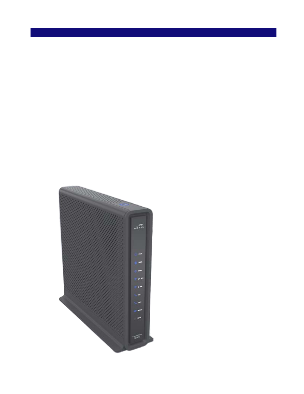
Get ready to experience the Internet’s express lane! Whether you’re checking out streaming
media, downloading ne w software, checking your email, or talking wi th friends on the
phone, the Touchstone TG2472 Telephony Gateway brings it all to you faster and more
reliably. All while providing toll quality Voice over IP telephone service and both wired and
wireless connectivity. It also provides a Lithium-Ion battery backup to provide continued
telephone service during power outages.
The Touchstone TG2472 Telephony Gateway provides four Ethernet connections fo r u se as
the hub of your home/office Local Area Network (LAN). The TG2472 also provides
802.11a/b/g/n/ac wireless connectivity for enhanced mobility and versatility. In addition,
the TG2472 provides for up to two separate lines of telephone service.
Chapter 1
The Telephony Gateway also offers integrated MoCA 2 . 0 home networkin g providing
Internet access and transfer of multimedia content between devices over coaxial cable in
the home.
Release 24 STANDARD 1.1 January 2015 Touchstone TG2472 Telephony Gateway User Guide 5
Page 6

Installation is simple and your cable company will provide assistance to you for any special
requirements.
Getting Support
If you need assista nce with your ARRIS product please contact your cable company.
For additional technical information and product User Guides please visit the ARRIS
Support website at http://www.arris.com/consumer.
Chapter 1: Overview
Release 24 STANDARD 1.1 January 2015 Touchstone TG2472 Telephony Gateway User Guide 6
Page 7

Safety Require men t s
The ARRIS Telephony Gateway complies with the applicable requirements for
performance, construction, labeling, and information when used as outlined below:
CAUTION
Potential equipment damage
Potential loss of service
Connecting the Telephony Gateway to existing telephone wiring should only be performed by a
professional installer. Physical connections to the previous telephone provider must be removed
and the wiring must be checked; there must not be any voltages. Cancelation of telephone service is
not adequate. Failure to do so may result in loss of service and/or permanent damage to the
Telephony Gateway.
Chapter 2
CAUTION
Risk of shock
Mains voltages inside this unit. No user serviceable parts inside. Refer service to qualified personnel
only!
CAUTION
Risk of explosion
Replacing the battery with an incorrect type, heating a battery above 75°C, or incinerating a battery,
can cause product failure and a risk of fire or battery explosion. Do not dispose of in fire. Recycle or
dispose of used batteries responsibly and in accordance with local ordinances.
The Telephony Gateway is designed to be connected directly to a telephone.
Connecting the Telephony Gateway to the home’s existing telephone wiring should only
be performed by a professional instal ler.
Do not use product near water (i.e. wet basement, bath tub, sink or near a swimming
pool, etc.), to avoid risk of elec trocuti on .
Do not use the telephone to report a gas leak in the vicini ty of the leak.
The product shall be cleaned using only a damp, lint-free, cloth. No solvents or
cleaning agents shall be used.
Do not use spray cleaners or aerosols on the gateway .
Avoid using and/or connecting the equipment during an electrical storm, to avoid risk
of electrocuti on.
Do not locate the equipment within 6 feet (1.9 m) of a flame or ignition source (i.e. heat
registers, space he aters, fireplaces, etc.).
Use only power supply and power cord included with the equipment.
Equipment should be installed near the power outlet and should be easily -accessible.
Release 24 STANDARD 1.1 January 2015 Touchstone TG2472 Telephony Gateway User Guide 7
Page 8

Chapter 2: Safety Requirements
The shield of the coaxial cable must be connected to earth (grounded) at the entrance
to the building in accordance with applicable national electrical installation codes. In
the U.S., this is re quired by NFPA 70 (National Electrical Code) Article 820. In the
European Union and in certain other countries, CATV installation equipotential
bonding requirements are specified in IEC 60728-11, Cable networks for television
signals, sound signals and interactive services, Part 11: Safety. This equipment is
intended to be installed in accordance with the requirements of IEC 60728-11 for safe
operation.
If the equipment is to be installed in an area serviced by an IT power line network, as is
found in many areas of Norway, special attention should be given that the installation
is in accordance with IEC 60728-11, in particular Annex B and Figure B.4.
In areas of high surge events or poor grounding situations and areas prone to lightning
strikes, additional surge protection may be requir ed (i.e. PF11VNT3 from American
Power Conversion) on the AC, RF, Ethernet and Phone li nes.
When the Telephony Gateway is connected to a local computer through Ethernet
cables, the computer must be properly grounde d to the building/residence AC ground
network. All plug-in cards within the computer must be properly i nstalled and
grounded to the computer frame per the manufacturer’s specifications.
Ensure proper venti lation. Position the Telephony Gateway so that air flows freely
around it and the ventilation holes on the unit are not blocked.
Do not mount the Telephony Gateway on surfaces that are sensitive to heat and/or
which may be damaged by the heat generated by the modem, its power supply, or other
accessories.
FCC Part 15
This equipment has been tested and found to comply with the requirements for a Class B
digital device under Part 15 of the Federal Communications Commission (FCC) rules.
These requirements are intended to provide reasonable protection aga i nst harmful
interference in a residential installation. This equipment generates, uses and can radiate
radio frequency energy and, if not installed and used in accordance with the instructions,
may cause harmful interference to radio communications. However, there is no guarantee
that interference will not occur in a particular installation. If this equ i pment does cause
harmful interference to radio or television reception, which can be determined by turning
the equipment off and on, the user is encouraged to try to correct the interference by one
or more of the followi ng measures:
Reorient or relocate the receiving antenna.
Increase the separation between the equipment and receiver.
Connect the equipment into an outlet on a circuit different from that to which the
receiver is connected.
Consult the dealer or an experienced radio/TV technician for help.
WARNING
Changes or modifications to this equipment not expressly approved by the party responsible for
compliance could void the user’s authority to operate the equipment.
Release 24 STANDARD 1.1 January 2015 Touchstone TG2472 Telephony Gateway User Guide 8
Page 9

RF Exposure
This equipment c omplies with FCC radiation exposu re limits set forth for an uncontroll ed
environment. This equipment should be installed and operated with minimum distance of
7.9 inches (20cm) between the radiator and your body. This transmitter must not be colocated or operating in conjunction with any other antenna or transmitter.
Industry Canada Compliance
Under Industry Canada regulations, this radio transmitte r may only operate using an
antenna of a type and maximum (or lesser) gain appro ved for the transmitter by Industry
Canada. To reduce potential radio interference to other users, the antenna type and its gain
should be so chosen that the equivalent isotropically radiated powe r (e.i.r.p.) is not more
than that necessary for successful communication.
This device complies with Industry Canada l icense-exempt RSS standard(s). Operation is
subject to the followin g two conditions: (1) this device may not cause interference, and (2)
this device must accept any interference, including i nterference that may cause undesired
operation of the device.
Chapter 2: Safety Requirements
For Mexico
The operation of t his equipment is subject to the following two condition s: (1) This
equipment or device cannot cause harmful interference and (2) this equipment or device
must accept any interference, including interference that may cause some unwanted
operation of the equipment.
European Compliance
This product complies with the provisions of the Electromagnetic Compatib i lity (EMC)
Directive (89/336/EEC), the Amen d i ng Directive (92/31/EEC), the Low Voltage Directive
(73/23/EEC), and the CE Marking Directive (93/68/ EEC). As such, this product bears the
CE marking in accordance with the above applicable Directive(s).
A copy of the Declaration of Conformity may be obtained from: ARRIS International, Inc.,
3871 Lakefield Drive, Suite 300, Suwanee, GA 30024.
As indicated by this symbol, disposal of this product or battery is governed by
Directive 2002/96/EC of the European Parliament and of the Council on
waste electrical and electronic equipment (WEEE). WEEE could potentially
prove harmful to the environment; as such, upon disposal of the Telephony
Gateway the Directive requires that this product must not be disposed as
unsorted municipal waste, but rather collected separately and disposed of in
accordance with local WEEE ordinances.
This product complies with directive 2002/95/EC of the European Parliament
and of the Council of 27 January 2003 on the restriction of the use of certain
hazardous substances (RoHS) in electrical and electronic equipment.
Release 24 STANDARD 1.1 January 2015 Touchstone TG2472 Telephony Gateway User Guide 9
Page 10

Getting Started
About Your New Telephony Gateway
The Touchstone TG2472 Telephony Gateway is DOCSIS compliant with the following
features:
Speed: much faster than dialup or I SDN service; up to eight times faster than DOCSIS
2.0 cable modems.
Convenience: supports Ethernet and 802.11a/b/g/n/ac wireless connections; both can
be used simultaneously
Flexibility: provides two independent lines of telephone service as well as high speed
data
Compatibility:
Chapter 3
• Data services: DOC SIS 3.0 compliant an d backward-compatible with DOCSIS 2.0
or 1.1; supports ti ered data services (if offered by your cable -company)
• Telephony services: PacketCable™ 2.0 compliant
The TG2472 provides:
Wireless 802.11a/b/g/n/ac connectivity
Four Ethernet ports for connections to non-wireless devices
Up to two lines of telephone service
Integrated MoCA 2. 0 home networkin g
DOCSIS 3.0 compliant with Li-Ion backup battery
One USB host port (future support for e xternal USB device s)
What's in the Box
Make sure you have the following items before proceeding. Call your cable company for
assistance if anything is missing.
Telephony Gateway
Power Cord
Battery (not included with all models)
Wireless Connection Configuration Guide
Ethernet Cable
End User License Agreement
Release 24 STANDARD 1.1 January 2015 Touchstone TG2472 Telephony Gateway User Guide 10
Page 11
Items You Need
If you are installing the Telephony Gateway yourself, make sure you have the following
items on hand before continuing:
Telephony Gateway package: see What's in the Box (page 10) for a list of items in
the package.
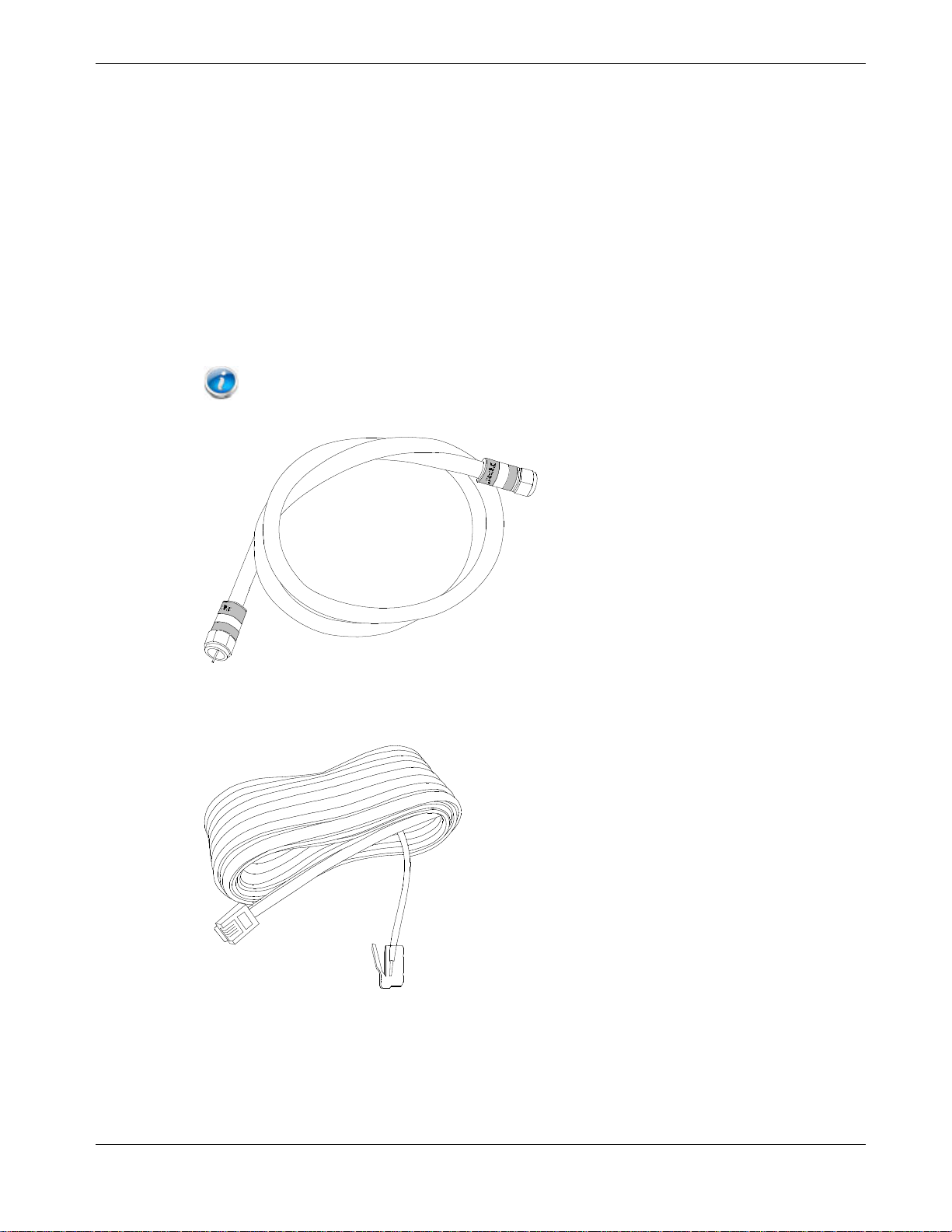
Coaxial cable (coax): This is a round cable with a connector on each end. It is the
same kind of wire used to connect to your television for cable TV. You can buy coax
from any electronics retailer and many discount stores; make sure it ha s connectors on
both ends. There are two types of conne c tors, slip-on and screw-on; the screw-on
connectors are be st for use with your Telephony Gateway. The coax should be long
enough to reach f rom your Telephony Gateway to the nearest cable outlet.
Note: For best performance, use high-quality RG-6 type coax cable and minimize or
eliminate splitters between the cable jack and the Data Gateway.
Chapter 3: Getting Started
Phone Cable: This is a standard phone cable with standard phone connectors (RJ11
type) on both ends. You can buy phone cables from any electronics retailer and many
discount stores.
Splitter (optional): provides an extra cable connection by splitting a single outlet
into two. You may need a splitter if you have a TV already connected to the cable outlet
that you want to use. You can buy a splitter from any e lectronics retailer and most
discount stores; you may also need a short piece of coax cable (with conn ectors); use it
to connect the splitter to the cable outlet and then connect the Telephony Gateway and
TV to the splitter .
Release 24 STANDARD 1.1 January 2015 Touchstone TG2472 Telephony Gateway User Guide 11
Page 12

Note: A splitter effectively cuts the signal in half and sends each half to its two outputs.
Using several splitters in a line may deteriorate the quality of your television, telephone, and/or
internet connection.
Information packet: your cable c ompany should furnish you with a pack et
containing information about your service and how to set it up. Read this information
carefully and contact your cable company if you have any questions.
Getting Service
Before trying to use your new Tel ephony Gateway, conta ct your local cable company to
establish an Internet account and telephone service. When you call, have the following
information ready:
the Telephony Gateway serial number and cable MAC add resses of the unit (printed on
the Telephony Gateway)
the model number of the Telephony Gateway (printed on the Telephony Gateway)
If the Telephony Gateway was provided by your cable company, they already have the
required information.
Chapter 3: Getting Started
In addition, you should ask your cable company the following question s:
Do you have any special system requirements or files that I need to downl oad after I
am connected?
When can I start using my Telephony Gateway?
Do I need a user ID or password to acce ss the Internet or my e-mail?
Will my phone number(s) change?
What new calling features will I have and how do I use them?
System Requirements
The Touchstone Telephony Gateway operates with most computers. The following
describes requirements for each operating system; see the documentation for your system
for details on enabling and configuring networking.
To use the Telephony Gateway, you need DOCSIS high-speed Internet servi ce from your
cable company. Telephone service requires that the cable company has PacketCable
support.
Recommended Hardware
The following hardware configuration is recommended. Computers not meeting this
configuration can still work with the TG2472, but may not be able to make maximum use
of TG2472 throughput.
CPU: P4, 3GHz or faster
RAM: 1GB or greater
Hard drive: 7200 RPM or faster
Release 24 STANDARD 1.1 January 2015 Touchstone TG2472 Telephony Gateway User Guide 12
Page 13
Ethernet: Gig-E (1000BaseT)
Windows
Windows XP , Windows Vista, Windows 7, or Windows 8. A supported Ethernet or
wireless LAN connection must be available.
MacOS
System 7.5 to MacOS 9.2 (Open Transport recommended) or MacOS X. A suppo rted
Ethernet or wirel ess LAN connection must be avail able.
Linux/other Unix
Hardware drivers, TCP/IP, and DHCP must be enabled in the kernel. A su pported
Ethernet or wirel ess LAN connection must be available.
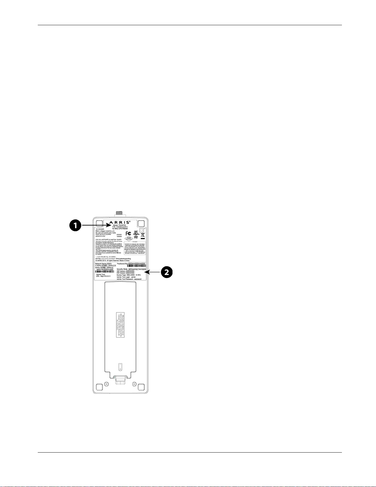
About this Manual
This manual covers the Touchstone TG2472 Telephony Gateway. The model number is on
the label affixed to the Telephony Gateway.
Chapter 3: Getting Started
1. Model Number
2. Security Label
Release 24 STANDARD 1.1 January 2015 Touchstone TG2472 Telephony Gateway User Guide 13
Page 14

What about Security
Having a high-speed, always-on connection to the Internet requires a certain amount of
responsibility t o other Internet users—including the need to maintain a reasonably secure
system. While no system is 100% secure, you can use the following tips to e nhance your
system’s security:
Keep the operating system of your computer updated with the latest security patches.
Run the system update utility at least w eekly.
Keep your email program updated with the latest security patches. In addi ti on, avoid
opening email containing attachments, or opening files sent through chat rooms,
whenever possible.
Install a virus checker and keep it updated.
Avoid providing web or file-sharing service s over your Tel ep hony Gate wa y. B eside s
certain vulnerability problems, most cable compan i es prohibit running servers on
consumer-level accounts and may suspend your account for violating your terms of
service.
Use the cable compa ny’s mail servers for sending email.
Chapter 3: Getting Started
Avoid using proxy software unless you are certain that it is not open for abuse by other
Internet users (some are shipped open by default). Criminals can take advantage of
open proxies to hide their identity when breaking into o ther computers or sending
spam. If you have an open proxy, your cable company may suspend your account to
protect the rest of the network.
The TG2472 ships with wireless LAN security set by default (for the same re asons that
you should run only secured proxies). See the security label on your product for the
factory security se ttings. If you need to modify the default wireless secu rity settings, see
Configuring Your Wireless Connection.
Ethernet or Wireless?
There are two ways to connect your computer (or other equipment) to the Telephony
Gateway. The following will help you decide which is best for you:
Ethernet
Ethernet is a standard method of connecting two or more computers into a Local Area
Network (LAN). You can use the Ethernet connection if y our computer has built-in
Ethernet hardware.
Note: To connect more than four computers to the TG2472 through the Ethernet ports, you
need an Ethernet hub (available at computer retailers).
Release 24 STANDARD 1.1 January 2015 Touchstone TG2472 Telephony Gateway User Guide 14
Page 15

Chapter 3: Getting Started
The Telephony Gateway package comes with one 4-foot (1.2m) Ethernet cable (the
connectors look like wide telephone connectors); y ou can purchase more cables if
necessary at a computer retailer. If you are connecting the Telephony Gateway directly to a
computer, or to an Ethernet hub with a cross-over switch, ask for Category 5e (CAT5e)
straight-through cable. CAT5e ca ble is required for gi g abit Ethernet (Gig-E), not regular
CAT5 cable.
Wireless
Wireless access lets you connect additional (wireless-capable) devices to Telephony
Gateway. The 802.11 wireless LAN standard allows one or more computers to access the
TG2472 using a wireless (radio) signal. These connections are in addition to the
connections supported via Ethernet.
Note: You can use the wireless connection if your computer has a built-in or aftermarket
plug-in wireless adapter. To learn more about which wireless hardware works best with your
computer, see your computer dealer.
Both
If you have two or more computers, you can u se Ethernet for up to four devices and
wireless for the others. To connect five or more computers to the Etherne t ports, you will
need an Etherne t hub (available at computer retailers.)
Release 24 STANDARD 1.1 January 2015 Touchstone TG2472 Telephony Gateway User Guide 15
Page 16

Battery Installation and Removal
Introduction
The TG2472 Telephony Gateway su pports a Lithium-I on backup battery to provide
continued telephone service during power outages. The battery backup is not intended to
take the place of AC power.
Note: For safety and regulatory purposes, batteries are shipped outside of the Telephony
Gateway and must be installed.
The TG2472 supports the following battery models:
Basic backup batte ry: provides up to 4 hours of backup time, depending on your
Telephony Gateway model and usage. It may be light gray or black.
Chapter 4
Basic Backup Battery (Gray)
Basic Backup Battery (Black)
Refer to Basic Battery Installation and Replacement (page 17).
Extended backup battery: provides up to 8 hours of backup time, depending on model
and usage. It has a strap between the battery guides. This is the standard battery for the
TG2472.
Extended Backup Battery
Refer to Extended Battery Installation and Replacement (page 18).
Release 24 STANDARD 1.1 January 2015 Touchstone TG2472 Telephony Gateway User Guide 16
Page 17

Your cable company may include a backup battery with your Telephony Gateway. You can
order any of the batteries shown here at http://www.arrismodemsite.com.
Basic Battery Installation and Replacement
This model of the Telephony Gateway has the ability to provide continued telephone
service during power outages. The battery backup is not intended to take the place of AC
power.
Use this procedure to install and to replace the back u p battery.
1. Press down and pull back on the l atch holding the battery door (on the bottom of the
Telephony Gateway). Pull the door toward you. Set the door aside in a safe pl ace.
Chapter 4: Battery Installation and Removal
1 - Latch End
CAUTION
Risk of equipment damage
Improperly inserting the battery may damage the battery connector in the Telephony
Gateway. Carefully follow the instructions in the next step to avoid damage.
2. Hold the battery pack so that the guides on the battery align with the slots on the
Telephony Gateway and slide the battery into the bay.
Release 24 STANDARD 1.1 January 2015 Touchstone TG2472 Telephony Gateway User Guide 17
Page 18

Chapter 4: Battery Installation and Removal
1 - Battery Slots
2 - Battery Guides
Note: Batteries will not insert completely into the Telephony Gateway if not oriented
correctly. The battery should slide into the bay without significant force. Line up the guides on
the battery with the slots in the battery bay.
3. Push the battery pack into the bay u ntil it seats into place. If you are taking the
battery out of the Telephony Gateway, position your finger in the battery
opening area a nd use leverage to dislodge the battery wh ile pulling it
straight back.
Note: The Telephony Gateway will not begin operating until you apply AC power.
4. Replace the door. To do so, place the hinge tabs of the battery door into the receiver
slots inside the Telephony Gateway battery compartme nt on the opposite end of the
battery opening. Rotate the door toward the unit until the latch snaps back into place.
1 - Battery Compartment
2 - Receiver Slot
3 - Hinge Tab
Note: Telephony Gateways use a Lithium-Ion battery pack. Please recycle or dispose of the
battery responsibly and in accordance with local ordinances.
Extended Battery Installation and Replacement
This model of the Telephony Gateway has the ability to provide continued telephone
service during power outages. The battery backup is not intended to take the place of AC
power.
Use this procedure to install or replace the backup battery.
Release 24 STANDARD 1.1 January 2015 Touchstone TG2472 Telephony Gateway User Guide 18
Page 19

Chapter 4: Battery Installation and Removal
1. Press down and pull back on the l atch holding the battery door (on the bottom of the
Telephony Gateway). Pull the door toward you. Set the door aside in a safe place.
1 - Latch End
CAUTION
Risk of equipment damage
Improperly inserting the battery may damage the battery connector in the Telephony
Gateway. Carefully follow the instructions in the next step to avoid damage.
2. Hold the battery pack so that the guides on the battery align with the slots on the
Telephony Gateway and slide the battery into the bay.
1 - Battery Slots
2 - Battery Guides
3 - Battery Pull Strap
Note: Batteries will not insert completely into the Telephony Gateway if not orien ted
correctly. The battery should slide into the bay without significant force. Line up the slots in the
battery bay with the guides on the battery and apply even pressure on both ends of the battery.
Release 24 STANDARD 1.1 January 2015 Touchstone TG2472 Telephony Gateway User Guide 19
Page 20

Chapter 4: Battery Installation and Removal
3. Push the battery pack into the bay until it latches into place. If you are taking the
battery out of the Telep hony Gateway , use the battery pull stra p to dislodge
the battery.
Note: The Telephony Gateway will not begin operating until you apply AC power.
4. Replace the door. To do so, place the tabs of the battery door into the slot inside the
Telephony Gateway battery compartment. Rotate the door toward the front of the
Telephony Gateway until the latch snaps back into place.
1 - Battery Compartment
2 - Receiver Slot
3 - Hinge Tab
Note: Telephony Gateways use a Lithium-Ion battery pack. Please recycle or dispose of the
battery responsibly and in accordance with local ordinances.
Release 24 STANDARD 1.1 January 2015 Touchstone TG2472 Telephony Gateway User Guide 20
Page 21

Installing and Connecting your Telephony Gateway
Before you start, m ake sure that:
You have contacted your cable company and verified that they provide data and
telephone service using standard DOCSIS technology.
You have all the items you need.
Cable, phone, and power outlets are available near the computer. If a cable outlet is not
conveniently located, your cable company can install a new one.
If you have ordered service, your cable company should configure the Telephony Gateway
automatically. You need only follow the instructions in this section to install and connect
the Telephony Gateway.
CAUTION
Risk of equipment damage
Only qualified installation technicians should connect the Telephony Gateway to house wiring.
Incumbent telephone service must be physically disconnected at the outside interface box before
making any connections.
Chapter 5
Release 24 STANDARD 1.1 January 2015 Touchstone TG2472 Telephony Gateway User Guide 21
Page 22

Front Panel
The front of the Telephony Gateway has the following indicators.
Chapter 5: Installing and Connecting your Telephony Gateway
1. WPS Button/LED: begins associating the Telephony Gateway with a wireless device.
LED indicates Wireless Protected Se tup (WPS) is active.
2. Power: indicates whether AC power is available to the unit.
3. US/DS: indicates upstream/downstream connectivity.
4. Online: indicates internet data transmission status.
5. 2.4 GHz: indicates the status of the 2.4 GHz wireless LAN.
6. 5 GHz: indicates the status of the 5 GHz wireless LAN.
7. Tel 1: indicates the status of telephone line 1.
8. Tel 2: indicates the status of telephone line 2.
9. Battery: in d icates the batte ry status.
10. MoCA: indicates connectivity between the Telephony Gateway and other home devices
connected via the MoCA network.
Release 24 STANDARD 1.1 January 2015 Touchstone TG2472 Telephony Gateway User Guide 22
Page 23

Rear Panel
The rear of the Telephony Gateway has the following connectors and controls.
Chapter 5: Installing and Connecting your Telephony Gateway
1. Reset button: resets t he Telephony Gateway as if you power cycled the unit. Use a
pointed non-metallic object to pre ss this button.
2. USB: USB host connect or - future support for ex ternal USB devices
3. Tel 1: connect or for the first phone line.
4. Tel 2: connector for the second phone line.
5. Ethernet (1 - 4): connectors for use with a computer LAN port.
6. Cable: connector for the coaxial cable.
7. Power: connector for the power cord.
Selecting an Installation Location
There are a number of factors to consider when choosing a location to install your
Telephony Gateway:
Is an AC outlet avai lable nearby? For best results, the outlet should not be switched and
should be close en ough to the Telephony Gateway that exte nsion cords are not
required.
Release 24 STANDARD 1.1 January 2015 Touchstone TG2472 Telephony Gateway User Guide 23
Page 24

Is a cable jack available? For best performance, keep the number of splitters between
the jack and cable drop to a minimum. Each splitter attenuates (reduces) the signal
available to the Telephony Gateway . A large number of splitters can slow down the
Internet connection and even affect your telephone service.
Can you easily run cables between the Telephony Gateway’s location and the phones?
If you are connecting devices to the Ethernet ports, can y ou easily run cables between
the Telephony Gateway’s location and those devices?
If you want to insta ll the Telephony Gateway on a desktop, is there enoug h spa c e on
either side to keep the vents clear? B locking the vents m ay cause overheating.
How close are your wireless devices? The Telephony Gateway wireless connection
range is typically 100–200 feet (30m–65m). A number of factors can affect connection
range, as described below.
Desktop Mounting In structions
Position the Telephony Gateway so that:
air flows freely around it
Chapter 5: Installing and Connecting your Telephony Gateway
the back faces the nearest wall
it will not fall to the floor if bumped or moved
the ventilation holes on the sides of the unit are not blocked
Factors Affecting Wireless Range
A number of factors can affect the usa ble range for wireless connections.
Increases range
Decreases range
Note: Note that decreasing the range of your wireless network may be beneficial, as long as
the decreased range is sufficient for your needs. By limiting your network’s range, you reduce
interference with other networks and make it harder for unwanted users to find and connect to your
network.
Raising the unit above the devices (for example, installing the
Telephony Gateway in the upper floor of a multi-story dwelling)
Adding a wireless extender to the network
Lowering the unit below the devices (for example, installing the
Telephony Gateway in a basement)
Metal or concrete walls between the Telephony Gateway and other
devices
Large metal appliances, aquariums, or metal cabinets between the
Telephony Gateway and other devices
Interference and RF noise (2.4 GHz wireless phones, microwave
ovens, or other wireless networks)
Note: Setting the transmit power level to High increases the range. Setting it to Medium or
Low decreases the range proportionately.
Release 24 STANDARD 1.1 January 2015 Touchstone TG2472 Telephony Gateway User Guide 24
Page 25

Connecting the Telephony Gateway
WARNING
Risk of injury or equipment damage
Connecting the Telephony Gateway to the home’s existing telephone wiring should only be
performed by a professional installer. Physical connections to the previous telephone provider must
be removed and the wiring must be checked; there must not be any voltage. Cancelation of
telephone service is not adequate. Failure to do so may result in loss of service and/or permanent
damage to the Telephony Gateway.
Chapter 5: Installing and Connecting your Telephony Gateway
1. Connect one end of the coax cable to the cable outlet or splitter, and the other end to
the Telephony Gateway’s Cable connector (6). Tighten the connections by hand, then
tighten an additional 1/8 turn with a wrench.
Note: For best performance, use high-quality coax cable and minimize or eliminate
splitters between the cable jack and the Telephony Gateway. If you are using MoCA for your
home network, MoCA filters must be installed on any legacy client devices. Your cable company
will install these filters for you.
2. Insert the plug from the power cord into the Power connector on the back of the
Telephony Gateway (7) and insert the power cord into a convenient AC outlet.
The Power light on the front of the Telephony Gateway lights up, then flashes once
(refer to the LED tables shown in Using the Telephony Gateway). See Troubleshooting
(page 38) if the Power light does not turn on.
Release 24 STANDARD 1.1 January 2015 Touchstone TG2472 Telephony Gateway User Guide 25
Page 26

3. Connect one end of the Ethernet cable to any Etherne t port on the back of the
Telephony Gateway, (5) and the other end to the Ethernet port on a computer, hub, or
broadband router.
Note: If you are connecting to a computer, use the Ethernet cable included in the
Telephony Gateway package.
4. Connect one end of the telephone cable to the telephone port on the back of the
Telephony Gateway (3 or 4). Connect the other end to the telephone.
Configuring Your Wireless Connection
The TG2472 ships with wireless LAN security set by default. See the security label on your
product for the factory security setti ngs.
Note: You must set up your computer and other client devices to work with the security
settings on the TG2472. Refer to the documentation for your client device for instructions on setting
security. On most computer systems you only need to select the network name (SSID) device and
enter the encryption key. If your computer or client device supports Wi-Fi Alliance WPS (Wireless
Protected Setup), activate WPS on your computer or client device and the TG2472 simultaneously to
easily set up your system security.
Chapter 5: Installing and Connecting your Telephony Gateway
1. Security Label
If you need to modif y the Telephony Gateway’s default wi reless security settings, or if you
want to configure any other wirele ss LAN settings, refer to the following instructions.
Release 24 STANDARD 1.1 January 2015 Touchstone TG2472 Telephony Gateway User Guide 26
Page 27

Accessing the Configuration Interface
Follow these steps to access the configuration interface. You should have already set up the
TG2472 as described in Installing and Connecting your Telephony Gateway (page 21).
1. If security has been properly set up on your computer to access the wireless LAN on the
TG2472, use the connection utility for your operating system to connect to the wirele ss
LAN using its netw ork name (SSID), as shown on the secu rity label.
2. If you cannot access t he wireless LAN, you must first establis h a wired Ethernet
connection between your computer and the TG2472.
3. In your web browser, open the page http://192.168 . 0.1/ to access the wireless router
setup.
The Login screen displays.
Note: The default user name is “admin”. The default password is “password ”, in lower
case letters.
4. Enter the user name and password and click the Apply button to log in.
The System Basic Setup screen displays.
Chapter 5: Installing and Connecting your Telephony Gateway
5. Use the online help information to set configuration parameters as required.
Note: Most configuration parameters that you may want to set can be accessed on the
System Basic Setup screen, including the security mode and setting a system password.
Setting Parental Controls
The Parental Control feature allows you to block specified keywords and web sites from
being accessed and also to specify tru sted computers in the network. Trusted computers
are not affected by the parental contr ol settings.
Finding the MAC Address of a Computer
In order to set up trusted computers you must first dete rmine the MAC add ress of those
computers.
Use the operating system of your computer to find its MAC address, as follows:
Windows: from the Start menu, find and select the
Connections
double-click either “Wireless Network Connection” fo r a wireless connection, or “Local
Area Connection” for an Ethernet connection. Next click the
or Windows 7), or click the Support tab and then the
“Physical Address” line shows the MAC address.
(Windows XP), or Network & Sharing Center (Windows Vista or Windows 7). The n
Control Panel. Double-click Network
Details button (Windows Vis ta
Details button (Windows XP). The
MacOS X: open System Preferences and click the Network icon. To find the Ethernet
MAC address, select
Built-in Ethernet from the Show dro p-d own , then click the Ethernet tab.
The “Ethernet ID” field shows the MAC address. To find the wireless MAC address, select
Airport from the Show drop-down, then click the Ai rport tab. The “Air port ID” field shows
the MAC address.
Release 24 STANDARD 1.1 January 2015 Touchstone TG2472 Telephony Gateway User Guide 27
Page 28

Linux: open a shell window and type /sbin/ifconfig (and press Enter). The wireless
interface is eth1 (unless there is no Ethernet adapter, i n which case the interface is eth0).
Making Your Parental Control Setting s
Follow these steps to set up your Paren tal Controls:
1. Access and log into the wireless configuration interface as explained in Accessing the
Configuration Interface (page 27).
Chapter 5: Installing and Connecting your Telephony Gateway
2. Click the
Firewall tab and then click Parental Controls in the side menu to display the
Parental Controls screen.
3. Check the
Enable Parental Controls checkbox and click the Apply button.
4. Configure any or all of the following parental controls:
Trusted MAC Addresses:
Enter the MAC addre sses of any “trusted” computers on the network and click the Apply
button. You can add two trusted computers. Once added, these trusted computers will
not be affected by the parental control settings. For example, you may wa nt the
computers of the f ather and mother t o be trusted, while the childrens’ computers have
parental controls in effect.
Note: Refer to the Finding the MAC Address of a Computer (page 27) for information on
determining the MAC address of your computer.
Keyword and Web Site Filtering:
You can add a list of key words and web sites that you want to block. To add a keyword
or web site to the li st, click the respec tive
from the list, first click its check box and then click the
Release 24 STANDARD 1.1 January 2015 Touchstone TG2472 Telephony Gateway User Guide 28
Add button. To delete a keyword or web site
Delete button.
Page 29

Add Keyword Filter Dialog Box
Add Web Site Filter Dialog Box
Chapter 5: Installing and Connecting your Telephony Gateway
Adding a Keyword or Web Site Filter
a. Enter the keyword in the Keyword field or web site URL address in the Web Site
field.
b. Click the checkboxes for the days you want access blocked, or click the All Week
checkbox for all week.
c. Set the start time and end time during the spe cified days (24-hour clock). (0:00
until 0:00 indicates all day, or just click the All Day checkbox.)
d. Click the
Add Keyword Filter or Add Web Site Filter button respectively. Then click the Apply
button.
Release 24 STANDARD 1.1 January 2015 Touchstone TG2472 Telephony Gateway User Guide 29
Page 30

Configuring Your Ethernet Connection
If your computer is equipped with a LAN card providing an Ethernet connection, you may
have to configure your computer’s TCP/IP settings. The steps that follow will guide you
through setting your computer’s TCP/I P settings to work with the Telephon y Gateway.
Requirements
Make sure you have the following before attempting to configure your Ethernet
connection:
Computer with Etherne t inte rfa ce
Ethernet cable (supplied)
IP address, subnet, gateway, and DNS information for installations not using DHCP
Chapter 6
How to use this Chapter
The following list shows the procedu res for modifying the TCP/IP settings on the
computer. The pr ocedure is slightly different depending on the operat i ng system that you
are using. Please ensure you are using the correct steps for the operating system on your
computer. Follow the links below for instructions to c onfigure your Ethe rnet connection on
your operating system.
TCP/IP Configuration for Windows XP (page 30)
TCP/IP Configuration for Windows Vista (page 31)
TCP/IP Configuration for Windows 7 or Windows 8 (page 31)
TCP/IP Configuration for MacOS X (page 32)
TCP/IP Configuration for Windows XP
Follow these steps to configure the Ethernet interface on a Windows XP o perating system.
TCP/IPv6 Note: This procedure shows the configuration of TCP/IPv4. TCP/IPv6 is not
installed or enabled by default in Windows XP. If your cable provider requires TCP/IPv6 you must
first install and enable it on your Windows XP system. Refer to Microsoft support materials on
Windows XP for installation instructions. Once installed and enabled, follow this same
configuration example, but select TCP/IPv6 at the appropriate step.
1. From the computer, select Start > Settings > Control Panel and double-click Network Connections
in the Control Panel.
The Network Connection window displays a list of LAN connections and associated
network adapters.
Release 24 STANDARD 1.1 January 2015 Touchstone TG2472 Telephony Gateway User Guide 30
Page 31

Chapter 6: Configuring Your Ethernet Connection
2. Double-click the local area connection to be used for your device’s network connection.
The Local Area Connection Status widow displays.
3. Click
4. Select
5. Click the
6. Click
Properties.
TCP/IP by clicking it one time. Then click Properties.
General tab. Then click Obtain an IP address automatically an d click OK.
OK to accept the new settings, and OK again to close the Properties window.
7. You may have to restart your com puter in order for your computer to o btain a new IP
address from the network.
TCP/IP Configuration for Windows Vista
Follow these steps to configure the Ethernet interface on a Windows Vis ta operating
system.
1. Open the Vista Control Panel.
2. Double-click
Window.
3. Click
Manage network connections. If prompted for a con nection, choose Local Area Connection.
The Network Connections window displays.
4. Double-click the
Network and Sharing Center to dis play the Network and Sharing Cente r
Local Area Connection to open the Properties window:
Note: If Windows requests permission to continue, click Continue.
5. Double-click Internet Protocol Version 4 (TCP/IPv4) to configure TCP/IPv4.
Note: If your cable provider requires TCP/IP version 6, double-click Internet Protocol
Version 6 (TCP/IPv6) to configure TCP/IPv6.
The TCP/IP properties window for the version you selected displays.
6. For either TCP/IPv4 or TCP/IPv6, select
server address automatically
7. Click
OK to accept the new settings and close the Properties window.
, unless instructed otherwise by your cable provider.
Obtain an IP address automatically and Obtain DNS
TCP/IP Configuration for Windows 7 or Windows 8
Follow these steps to configure the Ethernet interface on a Windows 7 or Windows 8
operating system .
1. Open the Windows Control Panel.
2. Click
3. Click
Network and Internet.
Network and Sharing Center.
4. Click
Release 24 STANDARD 1.1 January 2015 Touchstone TG2472 Telephony Gateway User Guide 31
Local Area Connection to open the Status window.
Page 32

5. Click Properties to open the Properties window.
Chapter 6: Configuring Your Ethernet Connection
6. Select
(TCP/IPv6) and click Properties to configure TCP/IPv6.
Internet Protocol Version 4 (TCP/IPv4) and click Properties to configure TCP/IPv4.
Note: If your cable provider requires TCP/IP version 6, select Internet Protocol Version 6
The TCP/IP properties window for the version you selected displays.
7. For either TCP/IPv4 or TCP/IPv6, select
server address automatically
8. Click
OK to accept the new settings and close the Properties window. Then click Close to
back out of the remaining setup screens.
, unless instructed otherwise by your cable provider.
TCP/IP Configuration for MacOS X
Follow these steps to configure the Ethernet interface on a MacOS X operating system.
1. Open System Preferences, either by choosing
by clicking the System Preferences icon in the dock.
2. Click the
3. Choose
menu.
Network icon.
Automatic from the Location dr op-down menu, and Built-in Ethernet from the Show
Obtain an IP address automatically and Obtain DNS
System Preferences from the Apple menu or
4. Choose the TCP/IP tab, if necessary.
If you are using
If your cable provi der requires
5. Choose
Using DHCP from the Configure IPv4 menu.
6. If necessary, click the
TCP/IPv4, go to step 5.
TCP/IPv6, go to step 8.
Renew DHCP Lease button.
7. Close the System Properties application.
TCP/IPv4 configuration is completed.
8. If you are using TCP/IPv6, click
9. Choose
Automatically from the Configure I Pv6 drop-down menu and click OK.
Configure IPv6 n ea r the bottom of the previous window.
10. Close the System Properties application.
Release 24 STANDARD 1.1 January 2015 Touchstone TG2472 Telephony Gateway User Guide 32
Page 33

Using the Telephony Gateway
This chapter describes th e contr ols and fea tures available on the Telephony Gateway, and
covers basic troubleshooting pro cedures.
Setting up Your Co mputer to Use the Telephony Gateway (page 33)
Indicator Lights for the TG2472 (page 33)
Using the Reset Button (page 36)
Resetting the Rou ter to Factory Defaults (page 37)
Setting up Your Computer to Use the Telephony Gateway
Follow the instructions in the information packet supplied by your cable company. Contact
your cable company if you need help setting up your computer.
Chapter 7
Indicator Lights for the TG2472
The Telephony Gateway has LED indicator lights to assist in troubleshooting.
Release 24 STANDARD 1.1 January 2015 Touchstone TG2472 Telephony Gateway User Guide 33
Page 34

Chapter 7: Using the Telephony Gateway
1. WPS Button/LED
2. Power
3. US/DS
4. Online
5. 2.4 GHz WiFi
6. 5 GHz Wi-Fi
7. Tel 1
8. Tel 2
9. Battery
10. MoCA
Wiring Problems
If the Telephony Gateway begins flashing all its light s f or more than 10 se conds, this
indicates a problem with the telephone wiring — the red and green wires may be shorted
(touching), or there may be undesired voltage on the l i nes. If this pattern persists for more
than 10 seconds, disconnect the telephone lines from the Telephony Gateway, then call a
wiring technicia n for assistance.
Patterns: Normal Operation (LAN and Telephone)
The following table shows light patterns for the Ethernet, MoCA and wire less LANs, and
the telephones, d u ri ng normal operation.
Mode Ethernet
(LEDs on rear
panel
connector)
2.4G Wi-Fi / 5G
Wi-Fi
Tel 1 / Tel 2 MoCA
AC Power Green LED On =
Computer with
1Gbps port
connected
Amber LED On
On = Wi-Fi enabled
Flash = Computer
activity
Off = Wi-Fi disabled
On = On-hook
Flash = Off-hook
Off = disabled
= Computer with
100
Mbps/10Mbps
port connected
Amber/Green
LED Flash =
Computer activity
Both LEDs Off =
Computer not
connected
No AC Power Off Off On = On-hook
Flash = Off-hook
Off = disabled
Firmware
Upgrade
(normal
operation)
(normal operation) (normal
operation)
On = MoCA
enabled
Flash = MoCA
network device
activity/traffic
Off = MoCA
disabled
Off
(normal
operation)
Release 24 STANDARD 1.1 January 2015 Touchstone TG2472 Telephony Gateway User Guide 34
Page 35

Patterns: Normal Op eration (WAN and Battery)
The following table shows light patterns during normal operation.
Mode Power US/DS Online Battery
Chapter 7: Using the Telephony Gateway
AC Power Good On On = Connected
No AC Power,
Battery Installed
No AC Power,
No Battery
Firmware
Upgrade
Patterns: Startup Sequence
The following tables show the Telephony Gateway light patterns during e ach phase of the
startup sequence. There are two phases of startup; the tel ephony phase and the cable
modem phase. Both are outlined below.
to the Internet
Flash = Not
connected to the
Internet
On = Internet
available
Off = Internet not
available
On = Battery good
or low
Off = Battery
missing
Flash = Battery
bad
Flash Off Off Off = Battery
power
Flash = Battery
bad
Off Off Off Off
On Flash On (normal
operation)
Telephony Startup Sequence
Power, US/DS,
Online
Off Off Off Off No power to modem
Flash Flash Flash Flash Power-on Self Test
On Flash Off Off Retrieving telephone
On Off Flash Off Retrieving telephone
On Flash Flash Off Activating telephone
Note: The US/DS indicator flashes during startup, and turns on when the Telephony
Gateway establishes a connection.
Telephone 1 Telephone 2 Battery Description
See "Cable Modem Startup Sequence
network information
line information
service
Normal Operation
Release 24 STANDARD 1.1 January 2015 Touchstone TG2472 Telephony Gateway User Guide 35
Page 36

Chapter 7: Using the Telephony Gateway
Cable Modem Startup Sequence
US/DS Online Description
Slow Flash
(1/second)
On
(until
Upstream
acquisition
starts)
Fast Flash
(3/second)
On
Slow Flash
acquisition)
On (when
modem IP
obtained)
Off Downstream acquisition in progress
Off Downstream acquisition completed
Off Upstream acquisition in progress
(during
Upstream acquisition completed, ready for
service
address
Using the Reset Button
Use the Reset button (1), on the back of the Telephony Gateway, to reset the modem and
perform initiali z ation as if you power cycled the unit. You may need to reset the Telephony
Gateway if you are having problems connecting to the I nternet. Using this but ton will be
rare.
Use a pointed non-metallic object to press thi s button. The Reset button is recessed to
prevent accidental resets.
Release 24 STANDARD 1.1 January 2015 Touchstone TG2472 Telephony Gateway User Guide 36
Page 37

Chapter 7: Using the Telephony Gateway
1. Reset button
2. USB
3. Tel 1
4. Tel 2
5. Ethernet (1 - 4)
6. Cable
7. Power
Resetting the Router to Factory Defaults
To reset the router to factory defau lts, press and hold the Reset button (1) on the back of
the Telephony Gateway for more than fifteen seconds. This restores the wireless setup
configuration and router configuration parameters to the factory defaults. You may need to
do this if a misconfiguration has locked out all access.
Booting from Battery
The TG2472 supports a “Boot from Battery” feature that allows the Tel ephony Gateway to
provide continued telephone service during power outages.
To start the TG2472 from its battery, follow these steps:
1. If a battery i s already instal led in the Telephony Gateway, remove i t.
2. Re-insert the battery into the Telephony Gateway (see Battery Installation and
Removal (page 16) for details).
3. Press the Reset button (1); the Power light should turn on immediately.
Release 24 STANDARD 1.1 January 2015 Touchstone TG2472 Telephony Gateway User Guide 37
Page 38

Troubleshooting
The Telephony Gateway is plugged in, but the Power light is Off
Check all power connections. Is the power cord plugged in firmly at both ends?
If you plugged the powe r cord into a power strip, make sure the strip is s witched on.
Avoid using an ou tlet controlled by a wall switch, if possible.
Finally, check the fuse or circuit breaker panel.
I'm not getting on the Internet (all connections)
It may take over 30 mi nutes to establi sh a connection the first time you power up your
Telephony Gateway, especially when many people are online. Always leave your Telephony
Gateway plugged into AC power and connected to the cable system.
Chapter 8
Check the front panel lights:
The Power and Online lights should be on.
If the Power light blinks for more than 30 minutes, call your cable company for
assistance.
Check your cable connections. Connectors should be tight. The coax cable should not be
pinched, kinked, or bent sharply—any of these can cause a break or short in the cable (you
may have to replace the cable). If you have one or more splitters between the Telephony
Gateway and CATV outlet, remove the splitters and connect the Telephony Gateway
directly to the outlet.
Proceed to the Et hernet or wireless solutions if necessary.
I'm not getting on the Internet (Ethernet)
If you are using a hub, is the hub turned on?
Are you using the right type of Ethern et cable? Use the supplied cable for direct connection
to a computer; use a cross-over cable for connection to a hub.
Press the Reset button on the back of the Telephony Gateway.
A misconfigurati on could lock out all access to the Telephony Gateway rou ter. If you think
this has happened, see Resetting the Ro u ter to Factory Defaults (page 37).
I'm not getting on the Internet (Wireless)
Check the indicator lights, see Using the Telephony Gateway (page 33) — the Wi-Fi light
should be on.
Release 24 STANDARD 1.1 January 2015 Touchstone TG2472 Telephony Gateway User Guide 38
Page 39

Does your connection utility discove r your wireless LAN? If you turned off “Broadcast
SSID” you need to ma nually ente r the name of your wireless LAN in the con nection utility.
Change your security mode to “disabled”. Enable on e of the other security modes as soon
as you find the problem.
A misconfigurati on could lock out all access to the Telephony Gateway rou ter. If you think
this has happened, see Resetting the Router to Factory Defaults (page 37).
My wireless Internet connection stops working sometimes
This is usually caused by interference. Two common sources are 2.4GHz “remote”
telephones and microwave ovens. If you cannot remove the interfering product, try using a
different channel or setting Protected Mode.
I can get on the Internet, but everything is slow
If the Web site you a re visiting is very popular, that site may be having trou ble servicing all
the requests. If other sites download quickly, wait for a few minutes and try again. Usage
during peak hours may also affect the connection speed.
Chapter 8: Troubleshooting
Other communica tions on the LAN, or interference with wireless connections, may slow
down your connection.
I don't have a dial tone when I pick up the phone - why?
In order for telephone service to be functional on the Telephony Gateway, telephone
service must have been purchased fr om the service provider and configured on your
Telephony Gateway. The following steps should help in identifying the source of the
problem.
1. Is the Power LED lit?
• If not, check to make sure the Telephony Gateway is plugged in and the outlet has
power.
• If the LED is lit, go to the next step.
2. Is the Online LED lit?
• If not, check the coax connection at the Telephony Gateway and the wall. Ensure
they are connected and tight. If they are and you do not have dial tone, contact your
service provider.
• If the Online LED is lit, go to the next step.
3. Is the Telephone (Tel 1 or Tel 2) LED lit?
• If not, phone service has not been set up on that line. Conta ct your service provider.
• If it is blinking, there is a phone off hook somewhere in the house. Find that phone
and hang it up.
• If it is lit, go to the ne xt step.
4. Is the phone plugged directly into the Telephony Gateway?
• Make sure the phone is plugged into the port on the back of the Telephony Gateway
labeled “Tel 1” for line 1, and “Tel 2” for line 2.
Release 24 STANDARD 1.1 January 2015 Touchstone TG2472 Telephony Gateway User Guide 39
Page 40

Chapter 8: Troubleshooting
• If so, try a different phone. Make sure the new phone is a work i ng phone.
• If a known good phone is used and you still don’t have dial tone, try a different
phone cable. If a new phone and cable do not restore dial tone, call your service
provider.
5. Is the Telephony Gateway plugged into a wall outlet?
• If so, unplug the phone connector at the back of the Telephony Gateway and plug in
a known working phone. If you now have dial tone, the problem is with the house
wiring. Contact your cable company or a quali fi ed wiring technician to correct the
house wiring. If you still do not have dial tone, contact your service pro vider.
Release 24 STANDARD 1.1 January 2015 Touchstone TG2472 Telephony Gateway User Guide 40
Page 41

Glossary
A
Amp-Hour
DNS
Domain Name Service (Server). An IP
service that associates a domain name
(such as www.example .com) with an IP
address.
A measure of battery capacity. For
example, a 1.0Ah battery can nominally
supply one Ampere of current for one
hour.
C
Category 5e (Cat5e)
A high-quality type of cable, used for
gigabit Ethernet (1000BaseT)
connections. When purchasing Ethernet
cables, always look for Category 5e cable.
Coaxial cable (coax)
A thin wire, used to connect your
television and Telephony Gateway to the
cable TV system. You can buy coax from
any electronics retailer and many
discount stores.
CPE
Customer Premise Equipment. This is the
equipment that is plugged in to the
Telephony Gateway; typically a computer
or hub.
DOCSIS
Data Over Cable System Interface
Specification. The interoperability
standards used for data communica tions
equipment on an HFC network.
Downstream
In an HFC network, the direction from
the head-end to the subscriber. Some
older cable documentation may ref er to
this as the forward path.
E
EMTA
Embedded Multimedia Terminal
Adapter. An MTA device that is
integrated with a cable modem.
Ethernet
A standard method of connecting two or
more computers in to a Local Area
Network (LAN).
EuroDOCSIS
Cross-over
An Ethernet cable u sed to connect two
hubs (or a hub and a cable modem)
together. Also, some Ethernet hubs may
have built-in cross-over on one or more
The European version of DOCSIS.
Event
An informational message used for
monitoring netwo rk status.
ports (which eliminates the need for a
cross-over cable).
D
DHCP
Dynamic Host Configuration Protocol.
An IP protocol used to provide an IP
address and location of services (such as
F
F-connector
The type of connector used on coax cable.
There are two common types of F-
connector, slip-on and screw-on. Use
coax with screw-on con nectors for
connecting your Telephony Gateway.
DNS and TFTP) needed by a device
connecting to the network. DHCP allows
the cable company to configure your
computer’s networking software for you.
Release 24 STANDARD 1.1 January 2015 Touchstone TG2472 Telephony Gateway User Guide 41
Firewall
A hardware or software device that
prevents unauthorized access to a private
Page 42

network from the In ternet. The TG2472
provides a built-in firewall.
G
Gateway
The device, usually a router, that
connects devices on a given IP subnet to
other IP subnets.
H
Headend
The “central office” in an HFC network.
The headend houses both video and data
equipment. In larger cable networks, a
“master” headend often feeds several
“remote” headends to provi de distri buted
services.
HTTP
HyperText Transf er Protocol.
LED
Light Emitting Diode. A semi-conductor
diode that emits li ght when current is
passed through it.
M
MAC address
A number that uniquely identifies any
device connected to a network. Your
cable company uses your Telephony
Gateway’s MAC address to authorize
access to the Intern et. The MAC address
is printed on a label on the bottom of
your Telephony Gateway.
P
Protocol
A set of rules and fo rmats that
determines the communication behavior
of network entities at a given layer.
Hub
A box with several Ethernet connectors.
Ethernet hubs provide a comm on poin t of
contact for all connected devices.
I
IP address
A number assigned to your computer by
your cable company, used to identify your
computer to other systems on the
Internet.
ISDN
Integrated Services Digital Network. A
digital telephony standard that pr ovides
communication speeds about twice as
fast as standard dialup.
L
LAN
Local Area Network. A network that
allows computers in a single location
(such as a building) to communicate with
one another.
Proxy
A device or program that stands in
between a server (for example, a web site)
and a client (your browser), providing a
way to relieve some of the burden from
the server. For example, your cable
company may have a web proxy that
keeps copies of popular web pages; the
proxy can send you those pages instead of
fetching them directly from the web site,
resulting in faster page loading and less
network congestion.
R
RF
Abbreviation for Radio Frequency. Some
literature refer s to coax as “RF cable” and
the connectors as “RF connectors.”
RJ-11
A standard 2-conductor modular
connector, commonly used in North
America for connecting telephones.
Release 24 STANDARD 1.1 January 2015 Touchstone TG2472 Telephony Gateway User Guide 42
Page 43

RJ-45
A standard 8-conductor modular
connector, commonly used on Ethernet
cable. An RJ-45 connector looks like a
wide RJ-11 (telephone) connector.
S
Splitter
A small box with three cable connectors:
one input and two outputs. You may need
a splitter if you have a TV already
connected to the cable outlet that you
want to use for you r Telephony Gateway.
You can buy a splitter from any
electronics retailer and most discount
stores.
SSID
Service Set IDentifier. A string of tex t (up
to 32 characters long) that unique ly
identifies a wireless LAN.
documentation m ay refer to this as t he
return path or reverse path.
W
WEP
Wired Equivale nt Privacy. A common
standard for enc rypting data sent over a
wireless LAN.
WPA
Wi-fi Protected Access. A standard for
encrypting data sent over a wireless L AN.
WPA offers improved security over WE P.
Switched outlet
A power outlet that m ay be turned on and
off using a wall switch. Usually intended
for lamps. Avoid plugging your compu ter
or Telephony Gateway into a switche d
outlet to avoid disruptions.
T
TCP/IP
Transmission Con trol Protocol/In ternet
Protocol. The protocols used to facilitate
communications a cross one or mo re
connected networks.
TDMA
Time Division Multiple Access. A method
used by DOCSIS-compliant cable
modems for sendin g upstream data wi th
minimal interference.
U
Upstream
The path from a subscriber device to the
headend. Some older cable
Release 24 STANDARD 1.1 January 2015 Touchstone TG2472 Telephony Gateway User Guide 43
Page 44

Touchstone TG2472 Telephony Gateway User Guide
Corporate Headquarters
ARRIS · Suwanee · Georgia · 30024 · USA
T: 1-678-473-2000 F: 1-678-473-8470
www.arris.com
 Loading...