

ARRIS SVG2500 User Manual
This document is uncontrolled pending incorporation in PDM
1 OVERVIEW
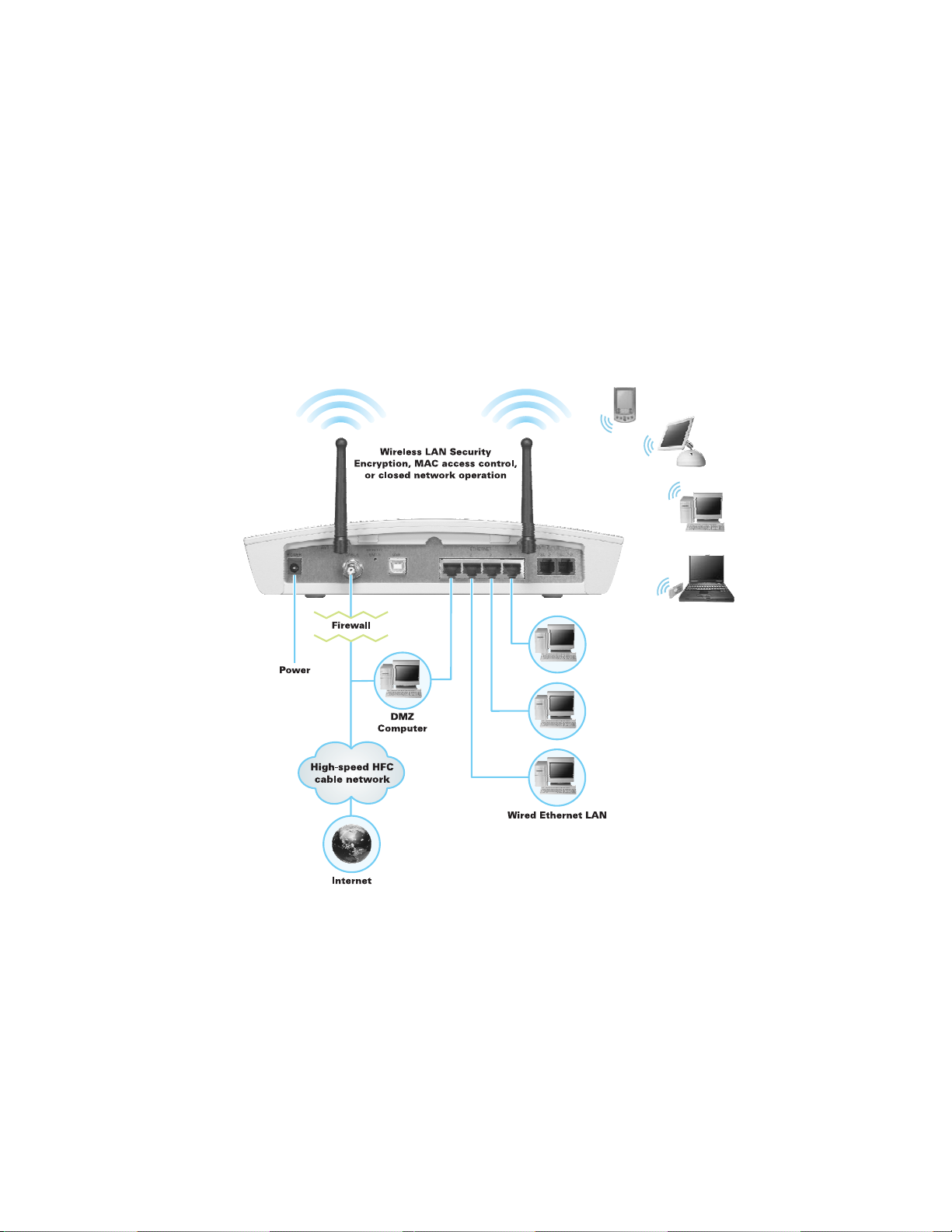
Security
The SVG2500 provides the following:
• A firewall to protect the SVG2500 LAN from undesired attacks over the Internet
• For wireless transmissions, data encryption and network access control
Network Address Translation (NAT) provides some security because the IP
addresses of SVG2500 LAN computers are not visible on the Internet.
This diagram does not necessarily correspond to the network cabling. A full
discussion of network security is beyond the scope of this document.
Figure 1-6 — SVG2500 Security Measures
15

This document is uncontrolled pending incorporation in PDM
1 OVERVIEW
Firewall
The SVG2500 firewall protects the SVG2500 LAN from undesired attacks and other
intrusions from the Internet. It provides an advanced, integrated stateful-inspection
firewall supporting intrusion detection, session tracking, and denial-of-service attack
prevention. The firewall:
• Maintains state data for every TCP/IP session on the OSI network and transport
layers
• Monitors all incoming and outgoing packets, applies the firewall policy to each
one, and screens for improper packets and intrusion attempts
• Provides comprehensive logging for all:
• User authentications
• Rejected internal and external connection requests
• Session creation and termination
• Outside attacks (intrusion detection)
You can configure the firewall filters to set rules for port usage. For information about
choosing a predefined firewall policy template, see
Pages.
Section 7, SVG2500 Firewall
DMZ
A de-militarized zone (DMZ) is one or more computers logically located outside the
firewall between an SVG2500 LAN and the Internet. A DMZ prevents direct access
by outside users to private data.
For example, you can set up a web server on a DMZ computer to enable outside
users to access your website without exposing confidential data on your network.
A DMZ can also be useful to play interactive games that may have a problem running
through a firewall. You can leave a computer used for gaming only exposed to the
Internet while protecting the rest of your network. For more information, see
Configuration Guidelines.
Port Triggering
When you run an application that accesses the Internet, it typically initiates
communications with a computer on the Internet. For some applications, especially
gaming, the computer on the Internet also initiates communications with your
computer. Because NAT does not normally allow these incoming connections:
• The SVG2500 has preconfigured port triggers for common applications.
• If needed, you can configure additional port triggers on the Advanced Port
Triggers Page.
Gaming
16

This document is uncontrolled pending incorporation in PDM
1 OVERVIEW
Wireless Security
Because WLAN data is transmitted using radio signals, it may be possible for an
unauthorized person to access your WLAN unless you prevent them from doing so.
To prevent unauthorized eavesdropping of data transmitted over your LAN, you must
enable wireless security. The default SVG2500 settings neither provide security for
transmitted data nor protect network data from unauthorized intrusions
The SVG2500 provides the following wireless security measures, which are
described in
Section 9, SVG2500 Wireless Pages.
To prevent unauthorized eavesdropping, you must encrypt data transmitted over the
wireless interface using one of the following:
• If all of your wireless clients support Wi-Fi
Motorola recommends using WPA. Otherwise, configure a Wired Equivalency
Privacy (WEP) key on the SVG2500 and each WLAN client.
• To protect LAN data from unauthorized intrusions, you can restrict WLAN access
to computers having one or both of:
• Known MAC addresses
.
®
Protected Access (WPA) encryption,
• The same unique network name (SSID) as the SVG2500
Restricting access to computers having the same network name is also called
“disabling SSID broadcasting” or “enabling closed network operation.”
Port Forwarding
The SVG2500 opens logical data ports when a computer on its LAN sends data,
such as e-mail messages or web data, to the Internet. A logical data port is different
from a physical port, such as an Ethernet port. Data from a protocol must go through
certain data ports.
Some applications, such as games and videoconferencing, require multiple data
ports. If you enable NAT, this can cause problems because NAT assumes that data
sent through one port will return to the same port. You may need to configure port
forwarding to run applications with special requirements.
To configure port forwarding, you must specify an inbound (source) port or range of
ports. The inbound port opens only when data is sent to the inbound port and closes
again after a specified time elapses with no data sent to it. You can configure up to
32 port forwarding entries using the Advanced Port Forwarding Page.
Virtual Private Networks
The SVG2500 supports multiple tunnel VPN pass-through operation to securely
connect remote computers over the Internet. The SVG2500:
• Is compatible with Point to Point Tunneling Protocol (PPTP) and Layer 2 Tunneling
Protocol (L2TP)
• Is fully interoperable with any IPSec client or gateway and ANX certified IPSec
stacks
17

This document is uncontrolled pending incorporation in PDM
2 INSTALLATION
The following topics provide information about installing the SVG2500 hardware:
Before You Begin
•
•
Precautions
•
Signing Up for Service
•
Computer System Requirements
•
Installing the Battery
•
Connecting the SVG2500 to the Cable System
Cabling the LAN
•
•
Installing USB Drivers
•
Connecting a PC to the SVG2500 USB Port
•
Obtaining an IP Address for Ethernet
•
Configuring TCP/IP
•
Installing the Telephone for VoIP
Wall Mounting Your SVG2500
•
For information about WLAN setup, see
Before You Begin
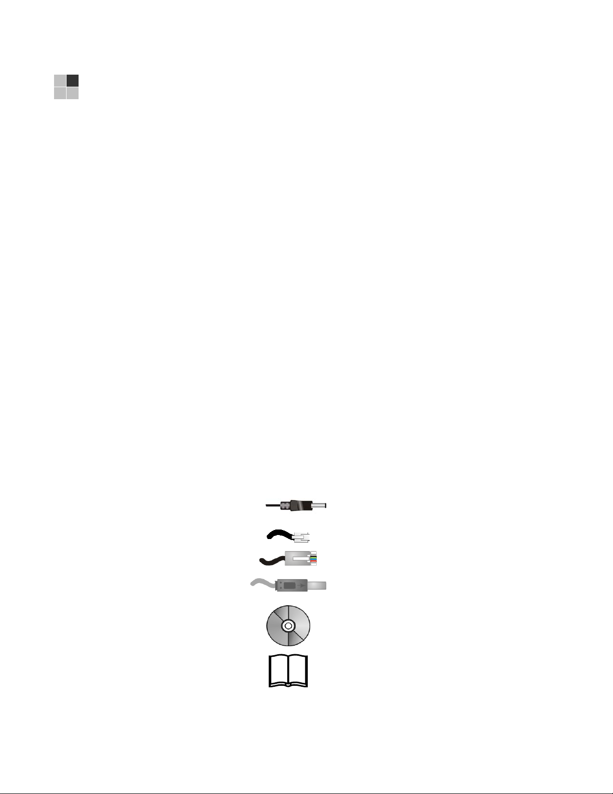
Before you begin the installation, check that the following items were included with
your Motorola SVG2500 Gateway:
Item Description
Power cord
Telephone cable (RJ-11)
Ethernet cable
USB cable
SVG2500 Installation
CD-ROM
Setting Up Your Wireless LAN.
Connects the SVG2500 to a power adapter that
connects to an AC electrical outlet
Connects to a telephone outlet
Connects to the Ethernet port
Connects to the USB port
Contains this user guide and USB drivers
SVG2500 Quick
Installation Guide
Contains basic information for getting started with
the SVG2500
19
This document is uncontrolled pending incorporation in PDM
2 INSTALLATION
You must have the latest service packs and patches installed on your computer for
your operating system. You will need 75-ohm coaxial cable with F-type connectors to
connect the SVG2500 to the nearest cable outlet. If a TV is connected to the cable
outlet, you may need a 5 to 900 MHz RF splitter and two additional coaxial cables to
use both the TV and the SVG2500.
Determine the connection types you will make to the SVG2500. Check that you have
the required cables, adapters, and adapter software. You may need:
Wireless LAN
Wired Ethernet
LAN
USB
Coaxial cable, RF splitters, hubs, and switches are available at consumer electronic stores.
Precautions
Postpone SVG2500 installation until there is no risk of thunderstorm or lightning
activity in the area.
To avoid potential shock, always unplug the power cord from the wall outlet or other
power source before disconnecting it from the SVG2500 rear panel.
To prevent overheating the SVG2500, do not block the ventilation holes on the sides
of the unit. Do not open the unit. Refer all service to your Internet Service provider.
Wipe the unit with a clean, dry cloth. Never use cleaning fluid or similar chemicals.
Do not spray cleaners directly on the unit or use forced air to remove dust.
Wireless adapter and driver software for each computer having a wireless
connection.
Ethernet cables and network interface cards (NICs) with accompanying
installation software
To connect more than four computers to the SVG2500, one or more Ethernet
hubs or switches
A USB cable and the SVG2500 Installation CD-ROM containing the software
for USB installation
20

This document is uncontrolled pending incorporation in PDM
2 INSTALLATION
Signing Up for Service
You must sign up with an Internet Service provider to access the Internet and other
online services. To activate your service, call your local Internet Service provider.
You need to provide the MAC address marked HFC MAC ID printed on the
Label on the SVG2500. You can record it in the SVG2500 Quick Installation Guide.
You should ask your Internet Service provider the following questions:
• Do you have any special system requirements?
• When can I begin to use my SVG2500?
• Are there any files I need to download after connecting the SVG2500?
• Do I need a user name or password to access the Internet or use e-mail?
Computer System Requirements
You can connect Microsoft Windows, Macintosh, UNIX®, or Linux® computers to the
SVG2500 LAN using one of the following:
• Ethernet — 10Base-T or 10/100Base-T Ethernet adapter with proper driver
software installed.
• Wireless — Any IEEE 802.11g or IEEE 802.11b device. This includes any Wi-Fi
certified wireless device, such as a cellular telephone equipped with this feature.
In addition, your computer must meet the following requirements:
• PC with Pentium class or better processor
• Windows
operating system with operating system CD-ROM available
®
2000, Windows® XP, Windows VistaTM, Macintosh, or Linux®
Bottom
• Minimum 16 MB RAM recommended
• 10 MB available hard disk space
You can use any web browser such as Microsoft
®
Navigator
, or Mozilla® Firefox® with the SVG2500.
®
Internet Explorer, Netscape
The following operating systems are not supported by the SVG2500. Microsoft
support for these products has ended:
®
• Windows
• Windows
• Windows
• Windows
• Windows NT
95
®
98
®
98 SE
®
Me
®
Note: UNIX, Linux, or Macintosh computers only use the Ethernet connection
21
.
This document is uncontrolled pending incorporation in PDM
2 INSTALLATION
You can use the USB connection with any PC running Windows 2000, Windows XP,
or Windows Vista that has a USB interface. The USB connection requires special
USB driver software that is supplied on the SVG2500 Installation CD-ROM. You can
upgrade your USB drivers from the Motorola Downloads page:
http://broadband.motorola.com/consumers/support/default.asp
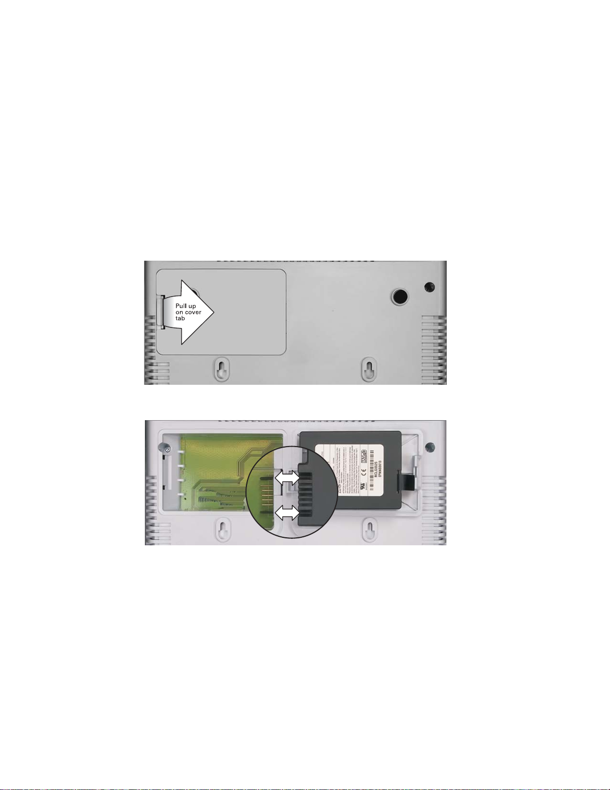
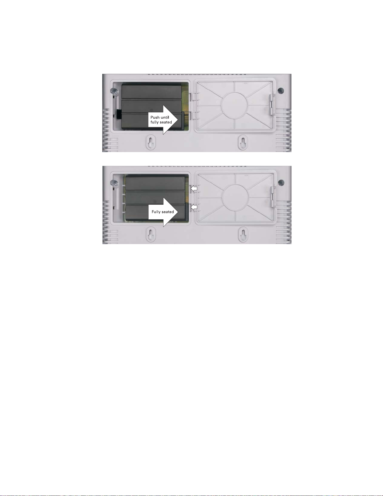
Installing the Battery
Before you begin the installation, you must first install the battery in your SVG2500.
Please read
proceeding.
1. Place the SVG2500 on a soft surface to access the bottom of the unit.
2. Pull up on the battery cover tab.
Safety Requirements for the SVG2500 Lithium-Ion Battery before
3. Align the key pins in the SVG2500 with the key slots on the battery for proper
contact.
22
This document is uncontrolled pending incorporation in PDM
2 INSTALLATION
4. The battery connectors should mate with the connectors on the SVG2500. Make
sure the pull-tab is accessible and does not prevent the battery cover from
closing properly.
5. Reinstall the battery cover with the alignment tabs seated downward.
It may take up to 12 hours for the battery to reach full charge when:
• It is installed for the first time.
• It is replaced.
• It is fully discharged.
Battery back-up times may vary based on many factors, including the battery age,
charging state, storing conditions, and operating temperature, as well as by factors
such as data activity and length of active telephone calls.
23
This document is uncontrolled pending incorporation in PDM
2 INSTALLATION
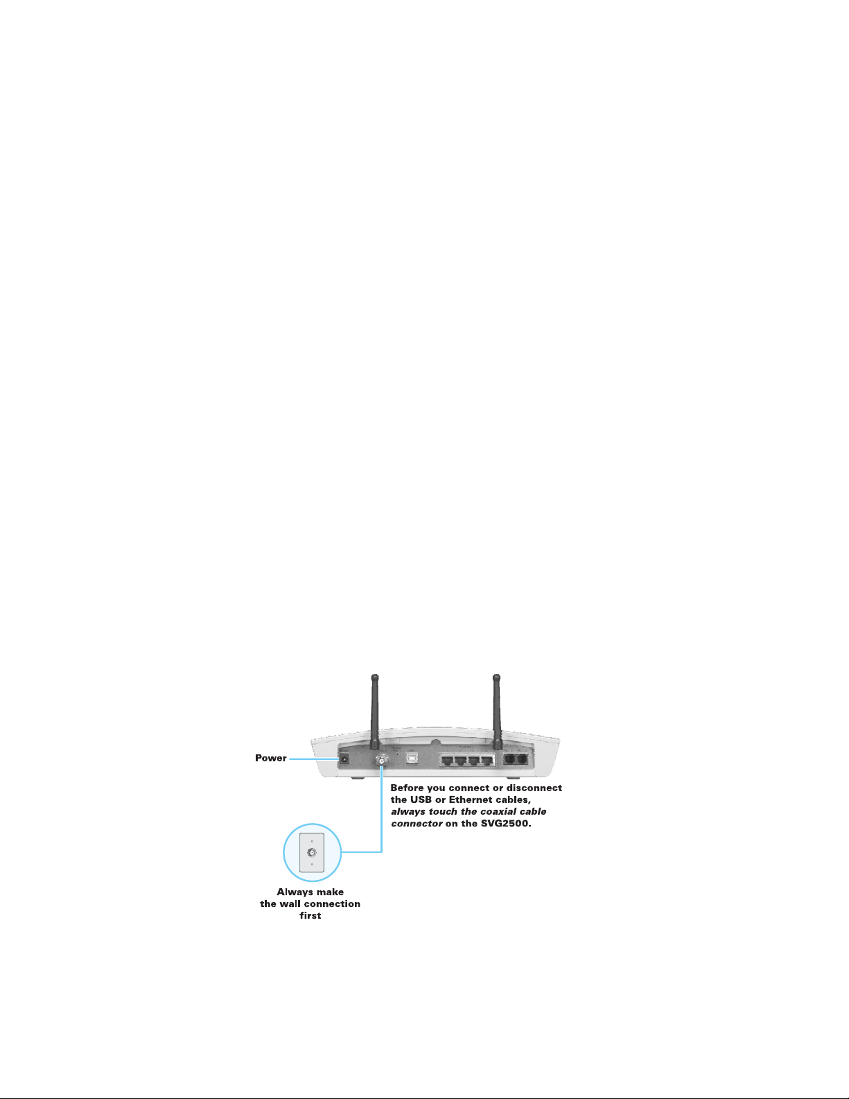
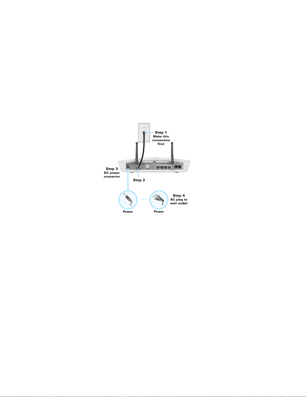
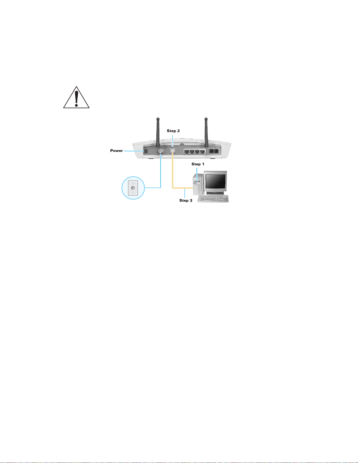
Connecting the SVG2500 to the Cable System
Before starting, be sure the computer is turned on and the SVG2500 is unplugged.
1. Connect one end of the coaxial cable to the cable outlet or splitter.
2. Connect the other end of the coaxial cable to the cable connector on the
SVG2500. Hand-tighten the connectors to avoid damaging them.
3. Plug the power cord into the power connector on the SVG2500.
4. Plug the power cord into the electrical outlet. This turns the SVG2500 on. You do
not need to unplug it when not in use. The first time you plug in the SVG2500,
allow it 5 to 30 minutes to find and lock on the appropriate communications
channels.
5. Check that the lights on the front panel cycle through this sequence:
POWER
ONLINE
DS
US
Turns on when AC power is connected to the SVG2500.
Indicates that the power is connected properly.
Flashes during SVG2500 registration and configuration.
Changes to solid green when the SVG2500 is registered.
Flashes while scanning for the downstream receive channel.
Changes to solid green when the receive channel is locked.
Flashes while scanning for the upstream send channel.
Changes to solid green when the send channel is locked.
24

This document is uncontrolled pending incorporation in PDM
2 INSTALLATION
Cabling the LAN
After connecting to the cable system, you can connect your wired Ethernet LAN.
Some samples are shown in
Wired Ethernet LAN. On each networked computer, you
must install proper drivers for the Ethernet adapter. Detailed information about
network cabling is beyond the scope of this document.
Installing USB Drivers
This section describes installing the USB driver on a PC connected to the USB port
on the SVG2500. Before connecting the PC to the SVG2500 USB port, perform one
of the following procedures applicable to the Windows version you are running:
•
Installing the Windows 2000 USB Driver
•
Installing the Windows XP USB Driver
•
Installing the Windows Vista USB Driver
The SVG2500 USB driver does not support Macintosh or UNIX computers. For those
systems, you can connect through Ethernet only.
Caution!
Be sure the SVG2500 Installation CD-ROM is inserted in the CD-ROM drive
before you plug in the USB cable.
If you have a problem installing the USB driver, remove it by performing one of the
following procedures applicable to the Windows version you are running:
Removing the Windows 2000 USB Driver
•
•
Removing the Windows XP USB Driver
When done, run the
Motorola USB Driver Removal Utility.
25
This document is uncontrolled pending incorporation in PDM
2 INSTALLATION
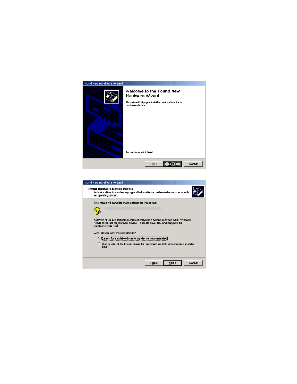
Installing the Windows 2000 USB Driver
1. Insert the SVG2500 Installation CD-ROM in the CD-ROM drive. This CD contains
the USB drivers and must be inserted and read by the PC before you connect the
SVG2500 to the PC.
2. Connect the USB cable as shown in USB Connection. A few seconds after you
complete the USB connection, the Found New Hardware window is displayed.
3. Click Next to display the Install Hardware Device Drivers window.
Motorola SURFboard SVG USB Gaeway
4. Be sure Search for a suitable driver for my device is selected.
26
This document is uncontrolled pending incorporation in PDM
2 INSTALLATION
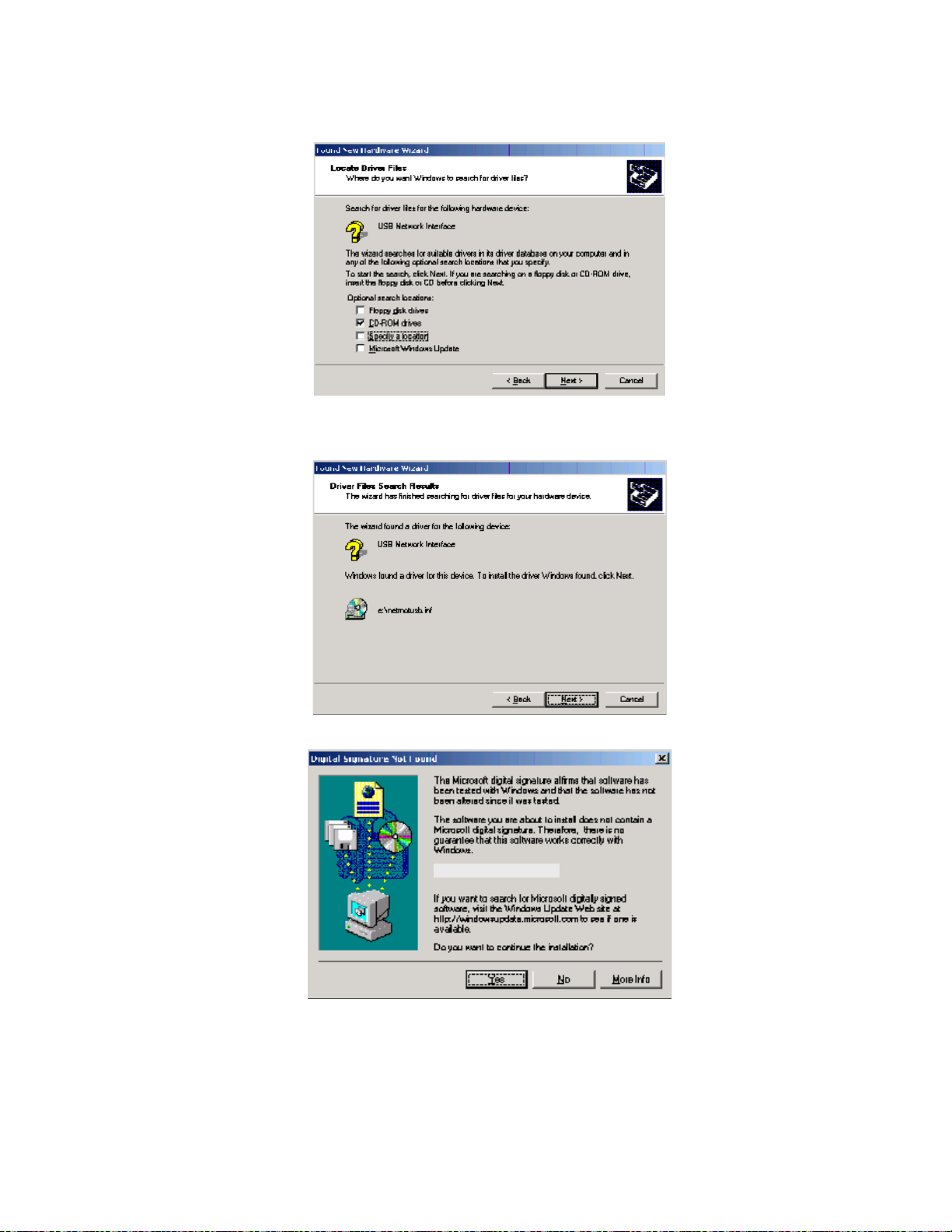
5. Click Next to display the Locate Driver Files window.
6. Checkmark CD-ROM drives only.
7. Click Next to display the Driver Files Search Results window.
8. Click Next to display the Digital Signature Not Found window.
Motorola USB SVG Modem
27
This document is uncontrolled pending incorporation in PDM
2 INSTALLATION
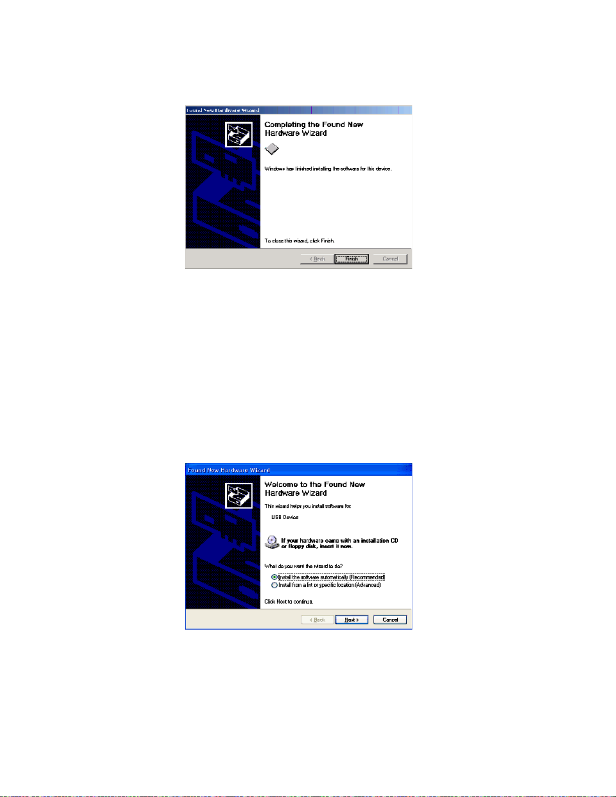
9. Click Yes to continue the installation. The Found New Hardware Wizard window is
displayed.
10. Click Finish to complete the installation.
When you finish setting up the USB driver, you can continue with Configuring TCP/IP.
Motorola USB SVG Modem
If you have any difficulties setting up the USB driver, perform
Driver in Windows 2000 and repeat the setup procedure.
Installing the Windows XP USB Driver
1. Insert the SVG2500 Installation CD-ROM in the CD-ROM drive. This CD contains
the USB drivers and must be inserted and read by the PC before you connect the
SVG2500 to the PC.
2. Connect the USB cable as shown in USB Connection.
A few seconds after you complete the USB connection, the Found New
Hardware Wizard window is displayed.
Removing the USB
3. Be sure Install the software automatically is selected.
28
This document is uncontrolled pending incorporation in PDM
2 INSTALLATION
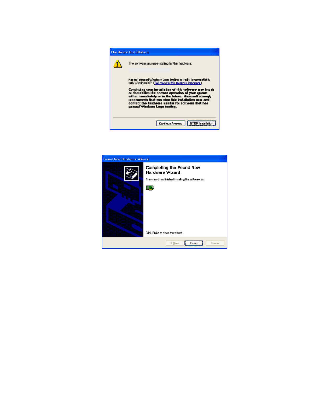
4. Click Next to display the Hardware Installation window.
Motorola USB SVG Modem
5. Click Continue Anyway. Windows automatically searches for the correct USB drivers
and installs them. If the installation is successful, the Found New Hardware
Wizard window is displayed:
Motorola USB SVG Modem
Although your SVG model number may be different than in the images in this
guide, the procedure is the same.
6. Click Finish to complete the installation. Otherwise, be sure the SVG2500
Installation CD-ROM is correctly seated in the CD-ROM drive.
When you finish setting up the USB driver, you can continue with
Configuring TCP/IP.
29
This document is uncontrolled pending incorporation in PDM
2 INSTALLATION
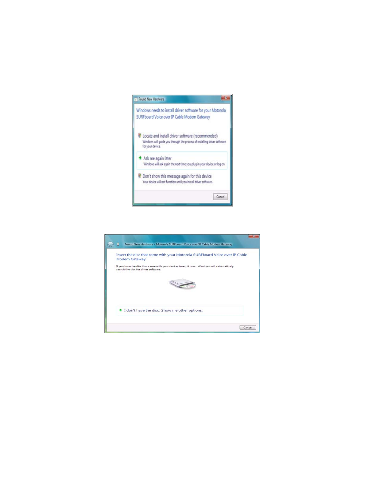
Installing the Windows Vista USB Driver
1. Be sure the USB cable is connected to both the computer and the SVG2500
gateway. If not, connect it as described in
A few seconds after you complete the USB connection, the Found New
Hardware window is displayed.
Connecting a PC to the USB Port.
2. Click Locate and install driver software. The Vista permissions pop up appears.
3. Click Continue to proceed. The Found New Hardware window is displayed.
30
This document is uncontrolled pending incorporation in PDM
2 INSTALLATION
4. Insert the SVG2500 Installation CD containing the USB drivers in the CD-ROM
drive. This CD must be inserted and read by the PC before you connect the
SVG2500 to the PC.
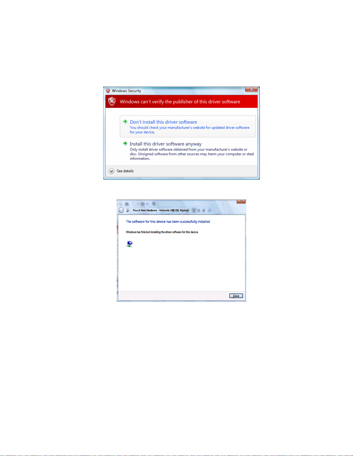
Windows automatically searches the CD for driver software. The Windows
Security window is displayed.
5. Click Install this driver software anyway. The Found New Hardware window is
displayed.
Motorola USB SVG Modem
6. Click Close. The SVG2500 USB interface is now installed and ready for operation.
When you finish installing the USB driver, you can continue with
Configuring TCP/IP.
31
This document is uncontrolled pending incorporation in PDM
2 INSTALLATION
Connecting a PC to the SVG2500 USB Port
You can connect a single PC running Windows 2000, Windows XP, or Windows Vista
to the SVG2500 USB port.
Caution!
Before plugging in the USB cable, be sure the SVG2500 Installation CD-ROM is inserted in the
PC CD-ROM drive.
To connect a PC to the SVG2500 USB port:
1. Insert the SVG2500 Installation CD-ROM in the CD-ROM drive to install the USB
driver. See
Installing USB Drivers for the applicable procedure for the Windows
version you are running.
2. Connect the USB cable to the USB port on the back of the SVG2500.
3. Connect the other end of the USB cable to the USB port on the computer.
Obtaining an IP Address for an Ethernet Connection
You can use either of the following two options to obtain the IP address for the
network interface on your computer:
• Retrieve the statically defined IP address and DNS address
• Automatically retrieve the IP address using the Network DHCP server
The Motorola SVG2500 gateway provides a DHCP server on its LAN. It is
recommended that you configure your LAN to obtain the IPs for the LAN and DNS
server automatically.
32
This document is uncontrolled pending incorporation in PDM
2 INSTALLATION
Windows 2000 or Windows XP
To retrieve the IP and DNS addresses, do the following on each Ethernet client
computer running Windows 2000 or Windows XP:
1. From the Windows Desktop, select Control Panel to display the Control Panel
window.
2. Select Network Connections to display the Network Connections window.
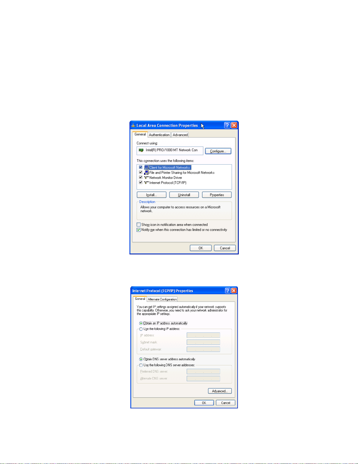
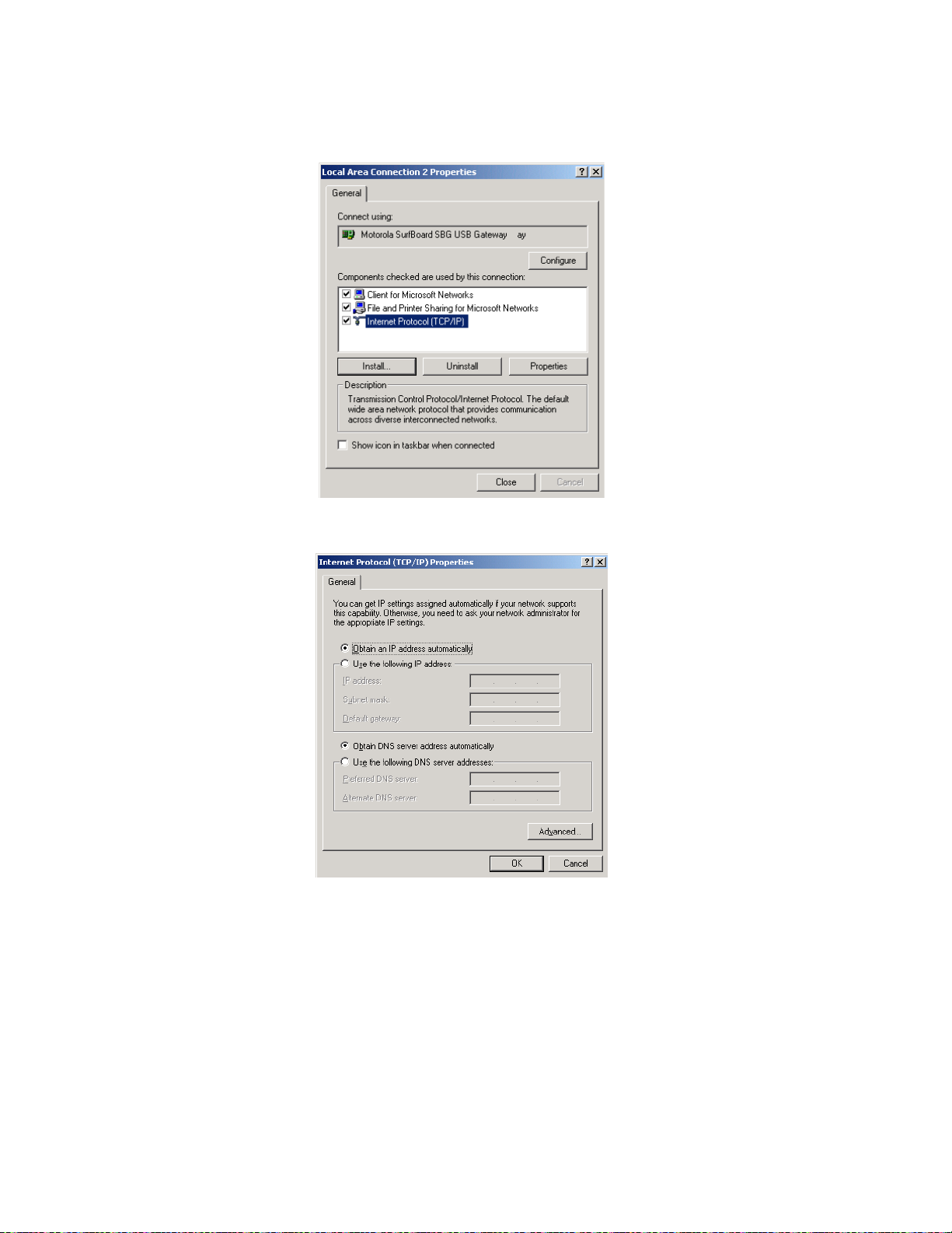
3. Right-click the Ethernet connection icon and select Properties to display the Local
Area Connection Properties window:
4. Under the General tab, select (or highlight) Internet Protocol (TCP/IP) and then
click Properties button.
The Internet Protocol (TCP/IP) Properties window is displayed:
33

This document is uncontrolled pending incorporation in PDM
2 INSTALLATION
5. Select the Obtain an IP address automatically radio button.
6. Select the Obtain DNS server address automatically radio button.
7. Click OK twice to save the IP settings.
8. Exit the Control Panel.
To automatically retrieve the IP Address, do the following on each Ethernet client
computer running Windows 2000 or Windows XP:
1. From the Windows Desktop, click Start to display the Windows Start menu.
2. Select Run to display the Run window.
3. Type
window.
4. Type
the DHCP server on the Motorola SVG2500.
5. Type
Windows Vista
To retrieve the IP and DNS addresses, do the following on each Ethernet client
computer running Windows Vista:
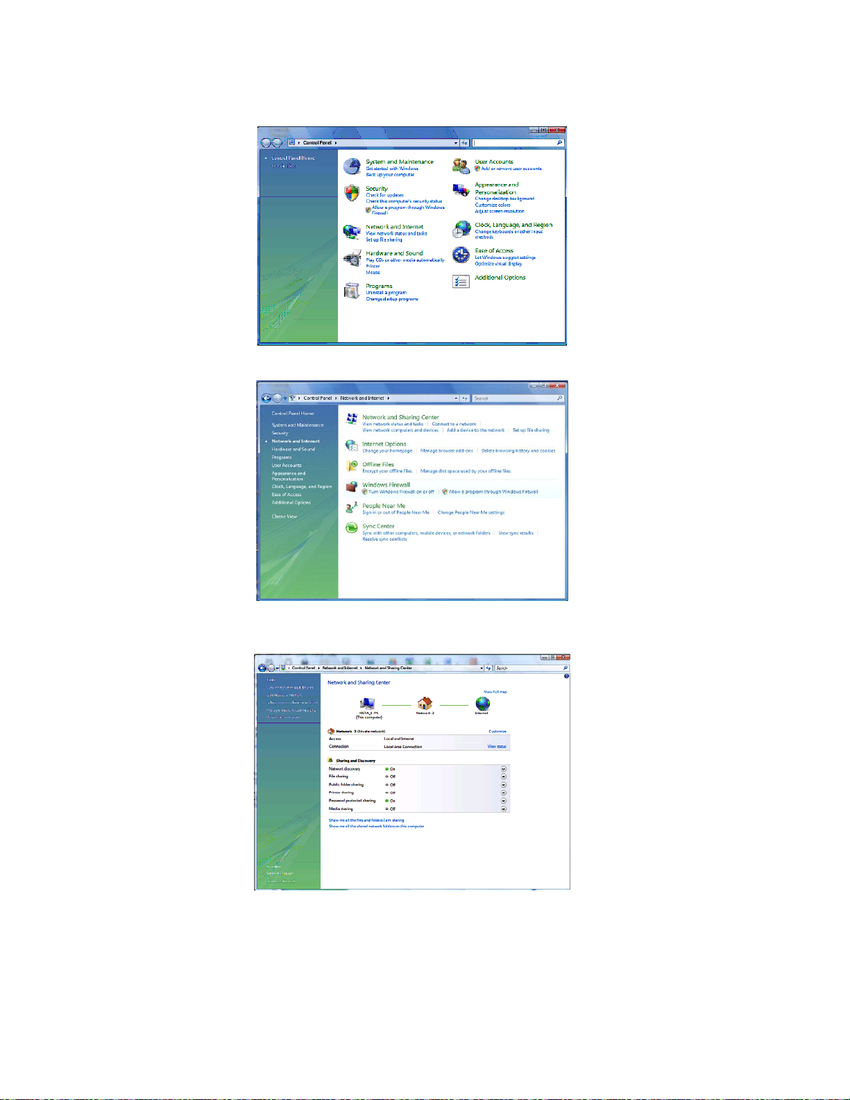
1. From the Windows Desktop, select Control Panel to display the Control Panel
Home window.
2. Click Network and Internet to display the Network and Internet window.
3. Click Network and Sharing Center to display the Network and Sharing Center window.
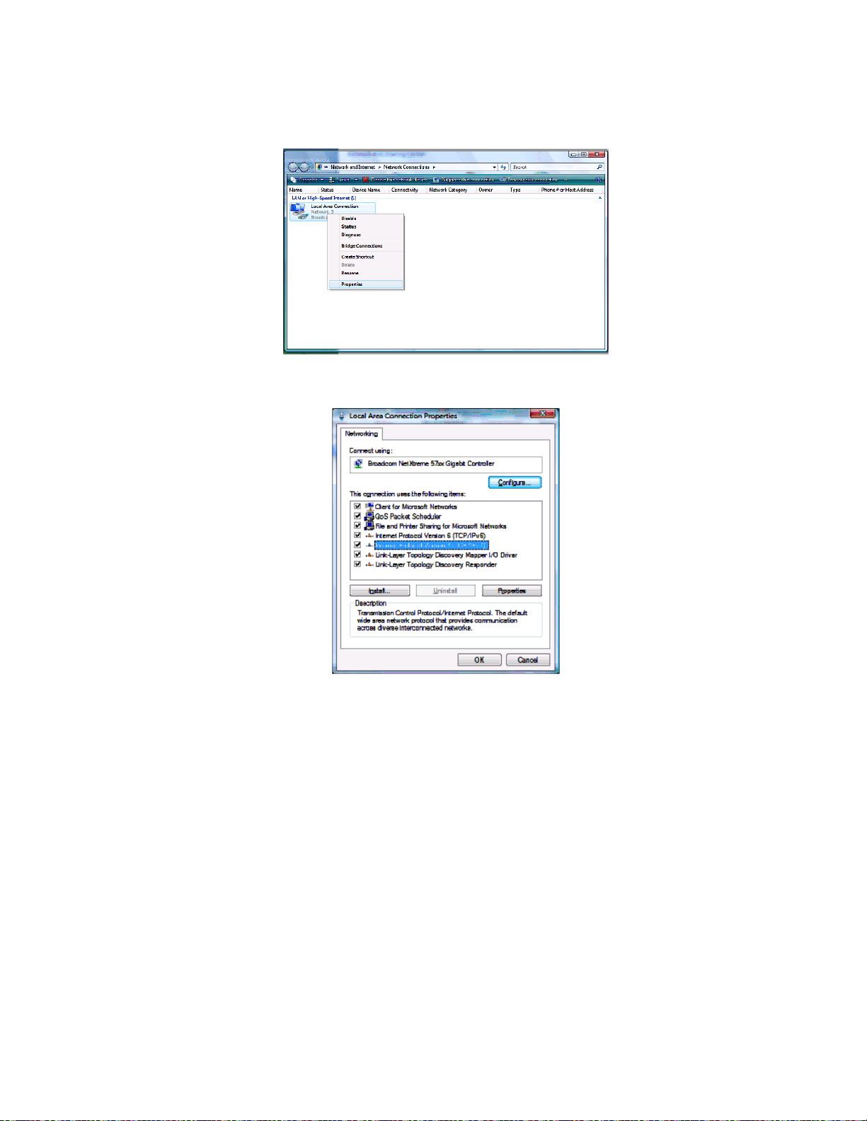
4. Click Manage network connections to display the LAN or High-speed Internet
connections window.
5. Right-click the network connection icon and select Properties from the drop-down
menu to display the Local Area Connection Properties window.
Note: If more than one network connection is displayed, Be sure to select your
network interface connection.
cmd in the Open entry box and then click OK to display a command prompt
ipconfig /renew and press Enter to obtain your computer’s IP address from
exit and press Enter to return to Windows.
Windows Vista may prompt you to allow access to the Network Properties
Options. If you see the message User Account Control - Windows needs your
permission to continue, select Continue.
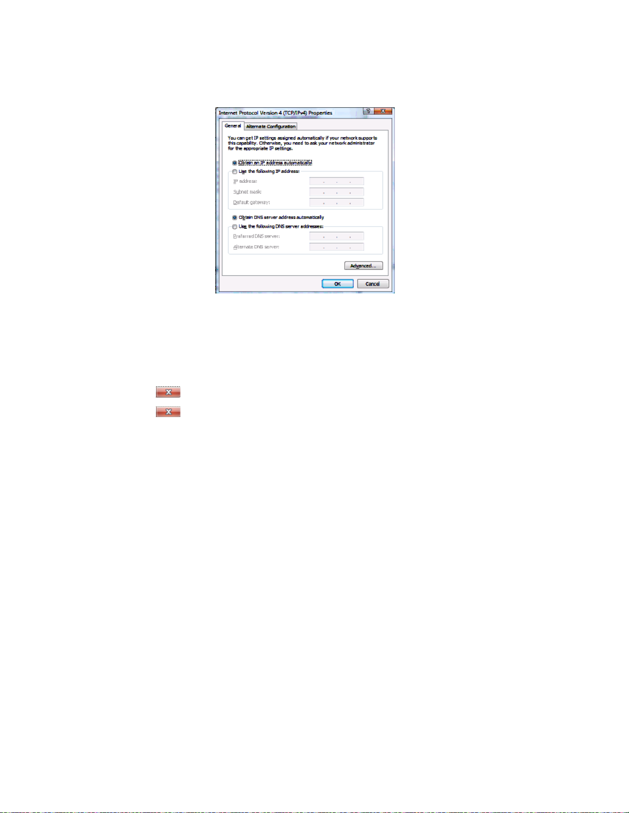
6. Select Internet Protocol Version 4 (TCP/IPv4) and click Properties to display the Internet
Protocol Version 4 (TCP/IPv4) Properties window.
7. Select the Obtain an IP address automatically radio button.
8. Select the Obtain DNS server address automatically radio button.
9. Click OK twice to close both network properties windows.
10. Click
11. Click
at the top right corner of each network window to close it.
to exit the Control Panel and save the IP settings.
34

This document is uncontrolled pending incorporation in PDM
2 INSTALLATION
Linux
To retrieve the IP Address, do the following on each client computer running Linux:
1. Type
2. Type
3. Type
su at the system prompt to log in as super-user.
ifconfig to display the network devices and allocated IP addresses.
pump -i <dev>.
where <dev> is the network device name
4. Type
ifconfig again to view the new allocated IP address.
5. Check to make sure no firewall is active on the device <dev>.
Macintosh or UNIX
Follow the instructions in the applicable user documentation.
Configuring TCP/IP
Make sure all client computers are configured for TCP/IP which is a protocol for
communication between computers. Perform one of the following for the operating
system you are running:
•
Configuring TCP/IP in Windows 2000
•
Configuring TCP/IP in Windows XP
•
Configuring TCP/IP in Windows Vista
• For Macintosh or UNIX systems, follow the instructions in the applicable
Macintosh or UNIX user documentation.
After configuring TCP/IP on your computer, you must verify the IP address. Perform
one of the following:
Verifying the IP Address in Windows 2000 or Windows XP
•
•
Verifying the IP Address in Windows Vista
• For Macintosh or UNIX systems, follow the instructions in the applicable
Macintosh or UNIX user documentation.
35
This document is uncontrolled pending incorporation in PDM
2 INSTALLATION
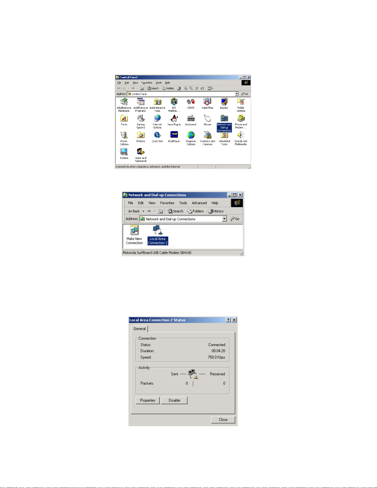
Configuring TCP/IP in Windows 2000
1. Select Control Panel from either the Windows Start menu or Windows
Desktop to display the Control Panel window.
2. Double-click Network and Dial-up Connections to display the Network and
Dial-up Connections window.
In the steps that follow, a connection number such as 1, 2, or 3 represents
PCs with multiple network interfaces. PCs having only one network interface
may be represented as “Local Area Connection.”
3. Double-click Local Area Connection number to display the Local Area
Connection number Status window. The value of number varies from system
to system.
36
This document is uncontrolled pending incorporation in PDM
2 INSTALLATION
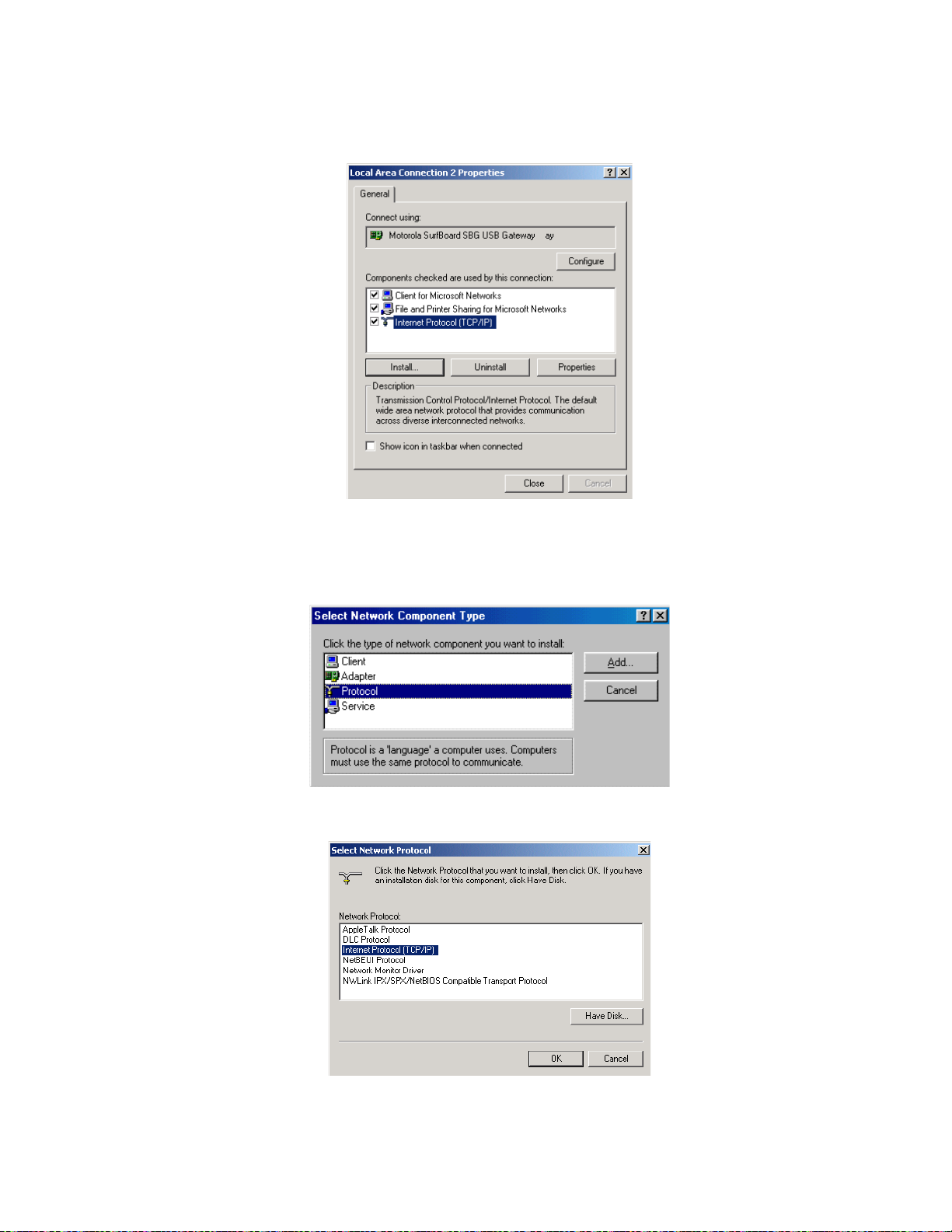
4. Click Properties to display the Local Area Connection number Properties
window. Information similar to the following displays.
5. If Internet Protocol (TCP/IP) is in the list of components, TCP/IP is installed.
You can skip to step 8.
6. If Internet Protocol (TCP/IP) is not in the list of components, click Install. The
Select Network Component Type window displays:
7. Click Protocol and then click Add. The Select Network Protocol window
displays:
37
This document is uncontrolled pending incorporation in PDM
2 INSTALLATION
8. Click Internet Protocol (TCP/IP) and then click OK. The Local Area Connection
number Properties window redisplays.
9. Click Internet Protocol (TCP/IP) and then click Properties to display the Internet
Protocol (TCP/IP) Properties window:
10. Be sure Obtain an IP address automatically and Obtain DNS server address automatically
are selected.
11. Click OK to save the TCP/IP settings and exit the TCP/IP Properties window.
12. Click OK to exit the Local Area Connection Properties window.
13. Click OK when prompted to restart the computer and click OK again.
14. When you complete the TCP/IP configuration, go to
Verifying the IP Address
in Windows 2000 or Windows XP.
38
This document is uncontrolled pending incorporation in PDM
2 INSTALLATION
Configuring TCP/IP in Windows XP
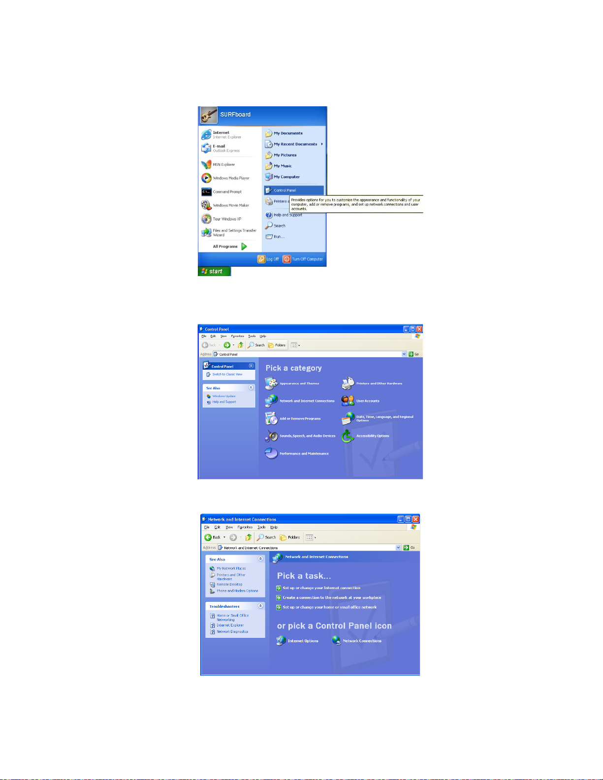
1. On the Windows desktop, click Start to display the Start window:
2. Click Control Panel to display the Control Panel window. The display varies,
depending on the Windows XP view options. If the display is a Category view as
shown below, continue with step 3. Otherwise, skip to step 5.
3. Click Network and Internet Connections to display the Network and Internet
Connections window:
39
This document is uncontrolled pending incorporation in PDM
2 INSTALLATION
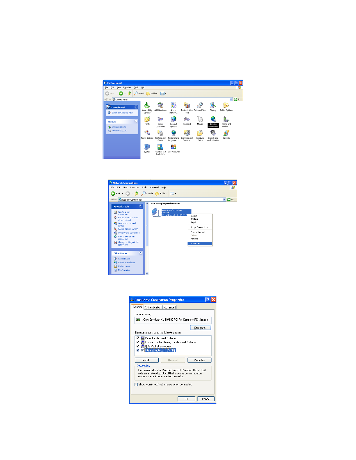
4. Click Network Connections to display the LAN or High-Speed connections. You can
skip to step 7.
5. If a Classic view similar to the screenshot below displays, double-click Network
Connections to display LAN or High-Speed Internet connections:
6. Right-click the network connection. If more than one connection is displayed, be
sure to select the one for your network interface:
7. Select Properties from the drop-down menu to display the Local Area Connection
Properties window:
40
This document is uncontrolled pending incorporation in PDM
2 INSTALLATION
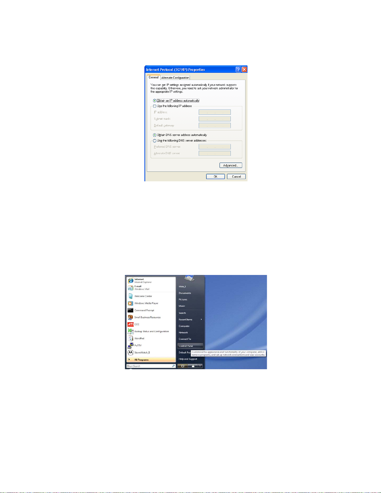
8. Select Internet Protocol (TCP/IP) and click Properties to display the Internet Protocol
(TCP/IP) Properties window:
9. Make sure Obtain an IP address automatically and Obtain DNS server address automatically
are selected.
10. Click OK to save the TCP/IP settings and exit the TCP/IP Properties window.
11. Click OK to exit the Local Area Connection Properties window.
When you complete the TCP/IP configuration, go to
Windows 2000 or Windows XP.
Configuring TCP/IP in Windows Vista
1. On the Windows desktop, click Start to display the Start window.
Verifying the IP Address in
41
This document is uncontrolled pending incorporation in PDM
2 INSTALLATION
2. Click Control Panel to display the Control Panel Home window.
3. Double-click Network and Internet to display the Network and Internet window:
4. Double-click Network and Sharing Center to display the Network and Sharing Center
window:
42
This document is uncontrolled pending incorporation in PDM
2 INSTALLATION
5. Click Manage network connections to display LAN or High-Speed Internet
connections.
6. Right-click the network connection and select Properties to display the Local Area
Connection Properties window.
7. If more than one connection is displayed, make sure to select the one for your
network interface.
Vista may prompt you to allow access to the Network Properties Options. If you
see the prompt, User Account Control -- Windows needs your permission to
continue, click Continue.
43
This document is uncontrolled pending incorporation in PDM
2 INSTALLATION
8. Select Internet Protocol Version4 (TCP/IPv4) and click Properties to display the Internet
Protocol Version4 (TCP/IPv4) Properties window.
9. Make sure Obtain an IP address automatically and Obtain DNS server address automatically
are selected.
10. Click OK to save the TCP/IP settings and close the Internet Protocol Version4
(TCP/IPv4) Properties window.
11. Click OK to close the Local Area Connection Properties window.
12. Click
13. Click
to close the Network Connections window.
twice to exit the Network and Sharing Center window and the Control
Panel.
When you complete the TCP/IP configuration, go to
Windows Vista.
Verifying the IP Address in Windows 2000 or Windows XP
Do the following to check the IP address:
1. On the Windows Desktop, click Start.
2. Select Run. The Run window is displayed.
3. Type
cmd and click OK to display a command prompt window.
Verifying the IP Address in
44
 Loading...