


H A N D B O O K |
A 8 5 |
|
|
P 8 |
5 |
|
P 8 5 / |
3 |
Arcam A85, P85 and P85/3 amplifiers |
English |
|
|
|
|
Amplificateurs Arcam A85, P85 et P85/3 |
|
|
|
|
|
Français |
|
|
|
|
|
Arcam-Verstärker A85, P85 und P85/3 |
|
|
|
||
Deutsch |
|
|
|
|
|
|
|
|
|
|
|
|
|
|

Safety guidelines
Safety instructions
This product is designed and manufactured to meet strict quality and safety standards. However, you should be aware of the following installation and operation precautions:
1. Take heed of warnings and instructions
You should read all the safety and operating instructions before operating this appliance. Retain this handbook for future reference and adhere to all warnings in the handbook or on the appliance.
2. Water and moisture
The presence of electricity near water can be dangerous. Do not use the appliance near water – for example next to a bathtub, washbowl, kitchen sink, in a wet basement or near a swimming pool, etc.
3. Object or liquid entry
Take care that objects do not fall and liquids are not spilled into the enclosure through any openings. Liquid filled objects such as vases should not be placed on the equipment.
4. Ventilation
Do not place the equipment on a bed, sofa, rug or similar soft surface, or in an enclosed bookcase or cabinet, since ventilation may be impeded. We recommend a minimum distance of 50mm (2 inches) around the sides and top of the appliance to provide adequate ventilation.
5. Heat
Locate the appliance away from naked flames or heat producing equipment such as radiators, stoves or other appliances (including other amplifiers) that produce heat.
6. Climate
The appliance has been designed for use in moderate climates.
7. Racks and stands
Only use a rack or stand that is recommended for use with audio equipment. If the equipment is on a portable rack it should be moved with great care, to avoid overturning the combination.
8. Cleaning
Unplug the unit from the mains supply before cleaning.
The case should normally only require a wipe with a soft, damp, lint-free cloth. Do not use paint thinners or other chemical solvents for cleaning.
We do not advise the use of furniture cleaning sprays or polishes as they can cause indelible white marks if the unit is subsequently wiped with a damp cloth.
A85/P85
9. Power sources
Only connect the appliance to a power supply of the type described in the operating instructions or as marked on the appliance.
10. Power-cord protection
Power supply cords should be routed so that they are not likely to be walked on or pinched by items placed upon or against them, paying particular attention to cords and plugs, and the point where they exit from the appliance.
11. Grounding
Ensure that the grounding means of the appliance is not defeated.
12. Power lines
Locate any outdoor antenna/aerial away from power lines.
13. Non-use periods
If the unit has a standby function, a small amount of current will continue to flow into the equipment in this mode. Unplug the power cord of the appliance from the outlet if left unused for
a long period of time.
14. Abnormal smell
If an abnormal smell or smoke is detected from the appliance, turn the power off immediately and unplug the unit from the wall outlet. Contact your dealer immediately.
15. Servicing
You should not attempt to service the appliance beyond that described in this handbook. All other servicing should be referred to qualified service personnel.
16. Damage requiring service
The appliance should be serviced by qualified service personnel when:
A.the power-supply cord or the plug has been damaged, or
B.objects have fallen, or liquid has spilled into the appliance, or
C.the appliance has been exposed to rain, or
D.the appliance does not appear to operate normally or exhibits a marked change in performance, or
E.the appliance has been dropped or the enclosure damaged.
Safety compliance
This product has been designed to meet the EN60065 international electrical safety standard.
2

Using this handbook
This handbook has been designed to give you all the information you need to install, connect, set up and use the Arcam A85 integrated amplifier or the P85 power amplifier. The A85 amplifier is described first, then the P85. The CR-389 remote control handset supplied with the A85 integrated amplifier is also described.
Your amplifier(s) may have been installed and set up by an authorised Arcam dealer. In this case, you may wish to go directly to the sections describing the use of this equipment.
Safety
Safety guidelines are set out on the inside front cover of this handbook.
Many of these items are common sense precautions, but for your own safety, and to ensure that you do not damage the unit, we strongly recommend that you read them.
English
Contents
Safety guidelines |
2 |
Safety instructions |
2 |
Safety compliance |
2 |
Using this handbook |
3 |
Safety |
3 |
Installation: A85 integrated amplifier |
4 |
Positioning the unit |
4 |
Connecting to loudspeakers |
4 |
Connecting to a power supply |
5 |
Connecting to other equipment |
5 |
Using your A85 integrated amplifier |
6 |
Front panel controls |
6 |
Recording |
7 |
Setting up your A85 integrated amplifier |
8 |
Using the remote control |
9 |
CR-389 remote control |
9 |
Installation: P85 power amplifier |
10 |
Connecting to power, loudspeakers and other |
|
equipment |
10 |
Remote switching |
10 |
Three channel option |
10 |
Using your P85 power amplifier |
11 |
Bi-wiring and bi-amping loudspeakers |
12 |
Before you start |
12 |
Bi-wiring your loudspeakers |
12 |
Bi-amping your system |
12 |
Service information |
13 |
Technical specification |
13 |
Guarantee |
14 |
On-line registration |
14 |
A85/P85
3
Installation: A85 integrated amplifier
TRIG
OUT
REMOTE
IN
1 2 3 4 5 6 7
Positioning the unit
Place your amplifier on a level, firm surface.
Avoid placing the unit in direct sunlight or near sources of heat or damp.
Ensure adequate ventilation. Do not place the unit in an enclosed space such as a bookcase or cabinet as both of these will impede air flow through the ventilation slots.
Connecting to loudspeakers
8 9 bk bl bm bn bo bp bq br
+ |
– |
Arcam A85 amplifier |
– |
+ |
|||
|
R |
|
L |
+ |
– |
+ |
– |
Right |
|
|
Left |
speaker |
|
|
speaker |
Wiring your loudspeakers
You can connect one or two pairs of loudspeakers to your amplifier, provided each pair is rated between 8–16Ω. If one or both pairs have an impedance of less than 8Ω, the combined load on the amplifier falls below 4Ω and could cause an overload. If so, the overload protection circuit engages and the amplifier will not work.
To connect one pair of loudspeakers, use the SP1 terminals.
SP1 and SP2 terminals 4
Both sets of loudspeaker terminals can be switched off by pressing the MUTE button on the remote control. To switch SP1 and SP2 independently, use the front panel switch 7(see page 6) or the remote control (see page 9).
Your amplifier is fitted with loudspeaker terminals to BFA (British Federation of Audio) standard specification.
BFA loudspeaker terminals
The terminal will accept spade terminals, bare wires or a BFA plug. BFA plugs are available from your Arcam dealer. To connect a bare wire or spade terminal, unscrew the red (or black) part of the loudspeaker terminal first.
Insert the wire or spade terminal and screw it back up.
CAUTION: Do not over tighten the loudspeaker terminals or use a wrench, pliers, etc., as this could cause damage to the terminals which will not be covered under warranty.
Connect the right speaker to the terminals on the back of your amplifier marked R and the left speaker to the terminals marked L.
Connect your loudspeakers so that the red (positive/+) terminal on each loudspeaker is connected to the red (positive/+) terminal on the amplifier. Your loudspeaker cables may be marked to show polarity (negative/– and positive/+), if not, then the positive terminal can usually be identified by a ridge or coloured marking.
Now connect your loudspeakers’ black (negative/–) terminals to the black (negative/–) terminals on the amplifier.
Ensure that no stray strands of inner wires are allowed to touch another cable or the amplifier’s casing. This can cause a short circuit and damage your amplifier!
A85/P85
4

Connecting to a power supply
Wrong plug?
Check that the plug supplied with the unit fits your supply and that your mains supply voltage agrees with the voltage setting (115V or 230V) indicated on the rear panel of the unit 2 before plugging in.
If your mains supply voltage or mains plug is different, consult your Arcam dealer or Arcam Customer Support on +44 (0)1223 203203.
The product must be earthed.
Mains lead
The appliance is normally supplied with a moulded mains plug already fitted to the lead. If for any reason the plug needs to be removed, it must be disposed of immediately and securely, as it is a potential shock hazard when inserted into the mains socket. Should you require a new mains lead, contact your Arcam dealer.
Plugging in
Push the plug (IEC line socket) of the power cable supplied with the unit into the socket (POWER INLET) 1in the back of the unit. Make sure it is pushed in firmly.
Put the plug on the other end of the cable into your power supply socket and switch the socket on.
Standby power
For remote standby operation, the amplifier’s control power supply is kept powered up all the time the unit is connected to the mains supply. The front panel power switch powers down all other circuitry. Power consumption in this mode is less than 2W.
This means that even though the power switch is off, it may be possible to hear a slight residual hum coming from the mains transformer inside the amplifier. This is perfectly normal. If the unit is to be left unused for an extended period, we recommend that it is disconnected from the mains supply by switching it
off at the wall socket.
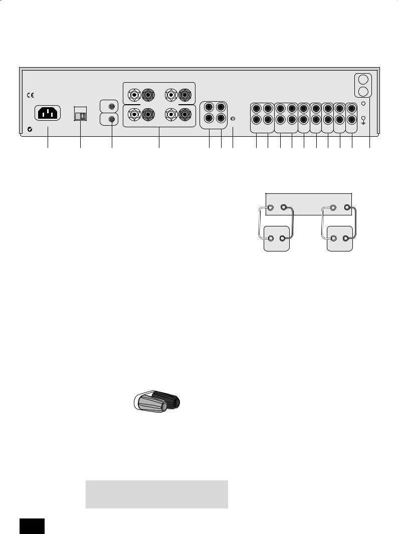
Connecting to other equipment
The use of high quality interconnect cables to and from your amplifier is recommended to ensure the best sound quality. Sockets marked L (and R) on your amplifier should only be connected to sockets marked L (and R) on other equipment. All the line inputs have the same sensitivity and may be used with equipment other than that labelled, if needed.
TAPE1/RECORD OUT 8– Connect these output sockets to the input sockets of your cassette deck (usually labelled
RECORD).
TAPE1/PLAY IN 9 – Connect these input sockets to the output sockets of your cassette deck (usually labelled PLAY). If you do not have a cassette deck you can use this input for other (line level) equipment, such as a CD player, tuner, VCR, etc., but not a turntable.
VCR/TAPE2 RECORD OUT bk– These output sockets can be connected to the input sockets of VCR/second recorder (usually labelled RECORD).
VCR/TAPE2 PLAY IN bl – Connect these input sockets to the output sockets of your VCR/second recorder (usually labelled PLAY). Alternatively, you can use this input for other (line level) equipment such as a CD player, tuner, etc., but not a turntable.
DVD bm– Connect this input to the audio outputs of a DVD player.
AV bn– Connect this input to audiovisual equipment such as a VCR, laserdisc player, satellite or Nicam tuner.
TUNER bo– Connect this input to the audio outputs of your radio tuner.
CD bp– Connect this input to the audio outputs of your CD player or DAC (digital to analogue converter).
AUX bq– Connect this input to the audio outputs of any unit with a line level output, e.g. tape deck, tuner etc.
NOTE: The AUX inputs must not be used if the phono module is fitted. When this is fitted AUX becomes an output carrying the equalised phono signal at line level.
PHONO br– As standard, phono inputs are blanked. Phono inputs are provided on a separate plug-in module which your Arcam dealer or distributor can supply and fit. This module
is compatible with most high output moving coil and moving magnet cartridges (MM) and low output moving coil cartridges (MC). MM or MC is selected via the MM/MC back panel switch.
Phono earth terminal – For connecting your turntable earth lead (if fitted). Note that this terminal must not be used as a safety earth.
TRIG OUT and REMOTE IN 3(12V in and out) – These connections are for use in multi-room installations. In normal use there is no need to make any connections to these sockets. If you are bi-amping with a power amplifier and wish to power both units on or off simultaneously, see page 11.
Pre/power amplifier connections
PWR IN 5– To use your integrated amplifier as a power amplifier, connect the output of your pre-amplifier to the PWR IN sockets.
Press in the PRE/PWR switch 7on the rear panel to select separate pre-amp/power amp mode. Under these
circumstances your A85 has exactly the same specification and performance as a power amplifier (see page 8).
PRE OUT 6– To use your integrated amplifier as a preamplifier, connect the PRE OUT sockets to the input sockets of your power amplifier. With a power amplifier of the correct gain (e.g. the P85 power amplifier) you can bi-amplify (‘bi-amp’)
suitable loudspeakers, giving significant improvements in sound quality (see page 12).
A85/P85
English
5
 Loading...