


 Loading...
HANDBOOK/MANUEL/HANDBUCH/HANDLEIDING |
A90 |
|
P90 |
|
P90/3 |
Arcam A90,P90 and P90/3 amplifiers |
English |
|
|
Amplificateurs Arcam A90,P90 et P90/3 |
Français |
|
|
Arcam-Verstärker A90,P90 und P90/3 |
Deutsch |
|
|
Arcam-versterkers A90,P90 en P90/3 |
Nederlands |
|

Safety guidelines
CAUTION |
ATTENTION |
|
|
RISK OF ELECTRIC |
RISQUE DE CHOC ELECTRIQUE |
SHOCK DO NOT OPEN |
NE PAS OUVRIR |
|
|
CAUTION: To reduce the risk of electric shock, do not remove cover (or back). No user serviceable parts inside. Refer servicing to qualified service personnel.
WARNING: To reduce the risk of fire or electric shock, do not expose this apparatus to rain or moisture.
The lightning flash with an arrowhead symbol within an equilateral triangle, is intended to alert the user to the presence of uninsulated ‘dangerous voltage’ within the product’s enclosure that may be
of sufficient magnitude to constitute a risk of electric shock to persons.
The exclamation point within an equilateral triangle is intended to alert the user to the presence of important operating and
maintenance (servicing) instructions in the literature accompanying the product.
CAUTION: In Canada and the USA, to prevent electric shock, match the wide blade of the plug to the wide slot in the socket and insert the plug fully into the socket.
Important safety instructions
This product is designed and manufactured to meet strict quality and safety standards. However, you should be aware of the following installation and operation precautions:
1. Take heed of warnings and instructions
You should read all the safety and operating instructions before operating this appliance. Retain this handbook for future reference and adhere to all warnings in the handbook or on the appliance.
2. Water and moisture
The presence of electricity near water can be dangerous. Do not use the appliance near water – for example next to a bathtub, washbowl, kitchen sink, in a wet basement or near a swimming pool, etc.
3. Object or liquid entry
Take care that objects do not fall and liquids are not spilled into the enclosure through any openings. Liquid filled objects such as vases should not be placed on the equipment.
4. Ventilation
Do not place the equipment on a bed, sofa, rug or similar soft surface, or in an enclosed bookcase or cabinet, since ventilation may be impeded. We recommend a minimum distance of 50mm (2 inches) around the sides and top of the appliance to provide adequate ventilation.
5. Heat
Locate the appliance away from naked flames or heat producing equipment such as radiators, stoves or other appliances (including other amplifiers) that produce heat.
6. Climate
The appliance has been designed for use in moderate climates.
7. Racks and stands
Only use a rack or stand that is recommended for use with audio equipment. If the equipment is on a portable rack it should be moved with great care, to avoid overturning the combination.
A90/P90
2
8. Cleaning
Unplug the unit from the mains supply before cleaning.
The case should normally only require a wipe with a soft, damp, lint-free cloth. Do not use paint thinners or other chemical solvents for cleaning.
We do not advise the use of furniture cleaning sprays or polishes as they can cause indelible white marks if the unit is subsequently wiped with a damp cloth.
9. Power sources
Only connect the appliance to a power supply of the type described in the operating instructions or as marked on the appliance.
10. Power-cord protection
Power supply cords should be routed so that they are not likely to be walked on or pinched by items placed upon or against them, paying particular attention to cords and plugs, and the point where they exit from the appliance.
11. Grounding
Ensure that the grounding means of the appliance is not defeated.
12. Power lines
Locate any outdoor antenna/aerial away from power lines.
13. Non-use periods
If the unit has a standby function, a small amount of current will continue to flow into the equipment in this mode. Unplug the power cord of the appliance from the outlet if left unused for a long period of time.
14. Abnormal smell
If an abnormal smell or smoke is detected from the appliance, turn the power off immediately and unplug the unit from the wall outlet. Contact your dealer immediately.
15. Servicing
You should not attempt to service the appliance beyond that described in this handbook. All other servicing should be referred to qualified service personnel.
16. Damage requiring service
The appliance should be serviced by qualified service personnel when:
A.the power-supply cord or the plug has been damaged, or
B.objects have fallen, or liquid has spilled into the appliance, or
C.the appliance has been exposed to rain, or
D.the appliance does not appear to operate normally or exhibits a marked change in performance, or
E.the appliance has been dropped or the enclosure damaged.
Safety compliance
This product has been designed to meet the IEC 60065 international electrical safety standard.

Using this handbook
This handbook has been designed to give you all the information you need to install, connect, set up and use the Arcam A90 integrated amplifier or the P90 power amplifier. The A90 amplifier is described first, then the P90. The CR-389 remote control handset supplied with the A90 integrated amplifier is also described.
Your amplifier(s) may have been installed and set up by an authorised Arcam dealer. In this case, you may wish to go directly to the sections describing the use of this equipment.
Safety
Safety guidelines are set out on the inside front cover of this handbook.
Many of these items are common sense precautions, but for your own safety, and to ensure that you do not damage the unit, we strongly recommend that you read them.
Contents |
|
Safety guidelines...................................................... |
2 |
Important safety instructions ...................................... |
2 |
Safety compliance..................................................... |
2 |
Using this handbook................................................. |
3 |
Safety....................................................................... |
3 |
Installation: A90 integrated amplifier........................ |
4 |
Positioning the unit .................................................... |
4 |
Connecting to loudspeakers....................................... |
4 |
Connecting to a power supply .................................... |
4 |
Connecting to other equipment................................... |
5 |
Using your A90 integrated amplifier ......................... |
6 |
Front panel controls................................................... |
6 |
Recording ................................................................. |
7 |
Setting up your A90 integrated amplifier .................. |
8 |
Using the remote control.......................................... |
9 |
CR-389 Remote Control ............................................. |
9 |
Installation: P90 power amplifer ............................. |
10 |
Connecting to power, loudspeakers and other |
|
equipment............................................................... |
10 |
Remote switching.................................................... |
10 |
Three channel option ............................................... |
10 |
Using your P90 power amplifier.............................. |
11 |
Bi-wiring and bi-amping loudspeakers..................... |
12 |
Before you start ...................................................... |
12 |
Bi-wiring your loudspeakers...................................... |
12 |
Bi-amping your system............................................. |
12 |
Remote-control codes ............................................ |
13 |
Service information................................................ |
14 |
Technical specifications.......................................... |
14 |
Guarantee.............................................................. |
15 |
On-line registration ................................................ |
15 |
English
A90/P90
3
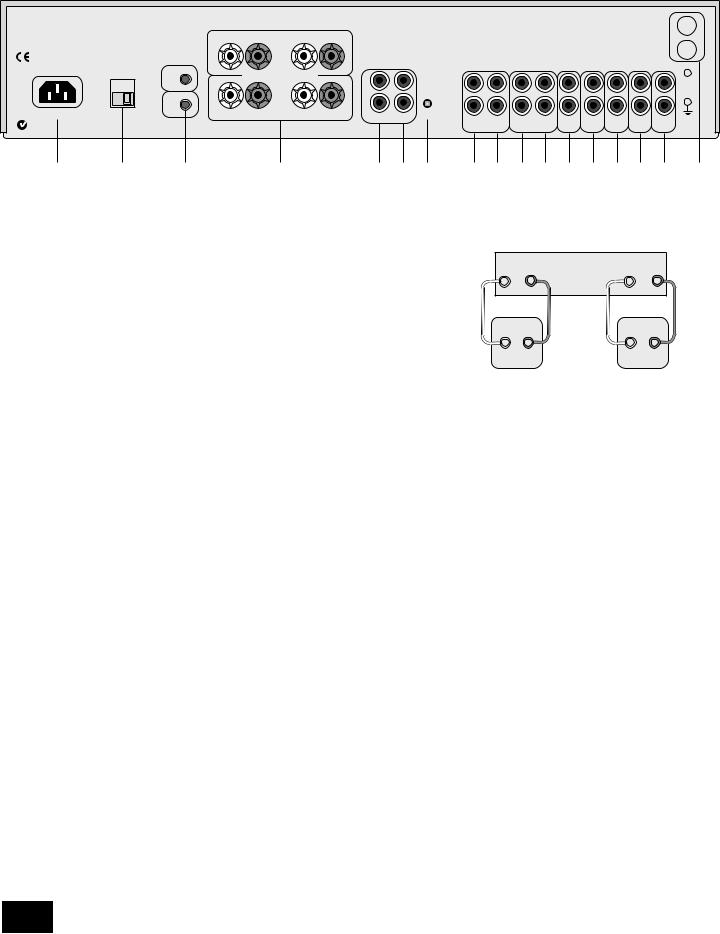
Installation: A90 integrated amplifier
TRIG
OUT
REMOTE
IN
1 2 3 4 5 6 7 89 bkblbm bnbobp bq br
Positioning the unit
Place your amplifier on a level, firm surface.
Avoid placing the unit in direct sunlight or near sources of heat or damp.
Ensure adequate ventilation. Do not place the unit in an enclosed space such as a bookcase or cabinet as both of these will impede air flow through the ventilation slots.
Connecting to loudspeakers
The red and black terminals on the back of the amplifiers 4 are used to make the connections to the loudspeakers. You can connect one or two pairs of loudspeakers to your amplifier, provided each pair is rated between 8–16Ω. (If one or both pairs have an impedance of less than 8Ω, the combined load on the amplifier falls below 4Ω and could cause an overload.) The pair designated ‘speaker 1’ (SP1) are connected to the lower set of terminals, while the pair designated ‘speaker 2’ (SP2) are connected to the upper set of terminals. To connect one pair of loudspeakers, use the SP1 terminals.
When connecting the speaker terminals of the amplifier with the terminals on the speakers, make sure that like polarities are matched (i.e., match ‘+’ with ‘+’ (usually red) and ‘–’ with ‘–’ (usually black)). Mismatching of polarities will result in a weak central sound, unclear orientation of the instruments and the sense of direction of the stereo being impaired.
There are two options for connecting the speaker cable to the amplifier:
+ |
– |
Arcam A90 amplifier |
– |
+ |
|||
|
R |
|
L |
+ |
– |
+ |
– |
Right |
|
|
Left |
speaker |
|
|
speaker |
Wiring your loudspeakers
Using spade terminals:
1.Loosen the terminal by turning it anti-clockwise
2.Insert the spade connecter under the terminal.
3.Tighten by turning clockwise.
Connecting to a power supply
Wrong plug?
Check that the plug supplied with the unit fits your supply and that your mains supply voltage agrees with the voltage setting (115V or 230V) indicated on the rear panel of the unit 2 before plugging in.
If your mains supply voltage or mains plug is different, consult your Arcam dealer or Arcam Customer Support on +44 (0)1223 203200.
The product must be earthed.
Mains lead
Using bare wire ended leads:
1.Strip back the insulation on the wire to reveal about 2cm of conductor (the metal inside the cable).
2.If the conductor is stranded, twist the strands together tightly to avoid loose strands making contact with the adjacent terminals or the back panel.
3.Loosen the terminal by turning it anti-clockwise
4.Insert the twisted wire through the hole in the terminal.
5.Tighten by turning clockwise.
When making connections with stranded bare ended wires, take great care that no individual strands of wire come into contact with the adjacent terminals or with the back panel. If this should happen, it will cause a short circuit on the output of the amplifier and could damage the amplifier.
The appliance is normally supplied with a moulded mains plug already fitted to the lead. If for any reason the plug needs to be removed, it must be disposed of immediately and securely, as it is a potential shock hazard when inserted into the mains socket. Should you require a new mains lead, contact your Arcam dealer.
Plugging in
Push the plug (IEC line socket) of the power cable supplied with the unit into the socket (POWER INLET) 1in the back of the unit. Make sure it is pushed in firmly.
Put the plug on the other end of the cable into your power supply socket and switch the socket on.
A90/P90
4

Standby power
For remote standby operation, the amplifier’s control power supply is kept powered up all the time the unit is connected to the mains supply. The front panel power switch powers down all other circuitry. Power consumption in this mode is less than 2W.
This means that even though the power switch is off, it may be possible to hear a slight residual hum coming from the mains transformer inside the amplifier. This is perfectly normal. If the unit is to be left unused for an extended period, we recommend that it is disconnected from the mains supply by switching it off at the wall socket.
Connecting to other equipment
The use of high quality interconnect cables to and from your amplifier is recommended to ensure the best sound quality. Sockets marked L (and R) on your amplifier should only be connected to sockets marked L (and R) on other equipment. All the line inputs have the same sensitivity and may be used with equipment other than that labelled, if needed.
TAPE1/RECORD OUT 8– Connect these output sockets to the input sockets of your cassette deck (usually labelled
RECORD).
TAPE1/PLAY IN 9– Connect these input sockets to the output sockets of your cassette deck (usually labelled PLAY). If you do not have a cassette deck you can use this input for other (line level) equipment, such as a CD player, tuner, VCR, etc., but not a turntable.
VCR/TAPE2 RECORD OUT bk– These output sockets can be connected to the input sockets of VCR/second recorder (usually labelled RECORD).
VCR/TAPE2 PLAY IN bl– Connect these input sockets to the output sockets of your VCR/second recorder (usually labelled PLAY). Alternatively, you can use this input for other
(line level) equipment such as a CD player, tuner, etc., but not a turntable.
DVD bm– Connect this input to the audio outputs of a DVD player.
AV bn– Connect this input to audiovisual equipment such as a VCR, laserdisc player, satellite or Nicam tuner.
TUNER bo– Connect this input to the audio outputs of your radio tuner.
CD bp– Connect this input to the audio outputs of your CD player or DAC (digital to analogue converter).
AUX bq– Connect this input to the audio outputs of any unit with a line level output, e.g. tape deck, tuner etc.
NOTE: The AUX inputs must not be used if the phono module is fitted. When this is fitted AUX becomes an output carrying the equalised phono signal at line level.
PHONO br– As standard, phono inputs are blanked. Phono inputs are provided on a separate plug-in module which your Arcam dealer or distributor can supply and fit. This module is compatible with most high output moving coil and moving
magnet cartridges (MM) and low output moving coil cartridges (MC). MM or MC is selected via the MM/MC back panel switch.
Phono earth terminal – For connecting your turntable earth lead (if fitted). Note that this terminal must not be used as a safety earth.
TRIG OUT AND REMOTE IN 3(12V in and out) – These connections are intended for use in multi-room installations.
TRIG OUT – This output provides a 12V signal whenever the unit is switched on (i.e., not off or in standby). This signal can be used to switch on automatically power amplifiers (or other equipment) connected to the A90, as they will come on when the A90 is activated. This is useful if the power amplifier is remote from the A90, or otherwise difficult to access.
REMOTE IN – This allows remote control signals to be received by the A90 if the remote sensor is covered (or otherwise not ‘visible’ to the remote control). An external sensor
is used to receive the signals from the remote control, which are then fed to the A90 (into this input) using a suitable cable. Remote control signals acceptable to the A90 must be in modulated RC5 format, with a voltage level of between 5V and 15V.
Note that in normal use there is no need to make any connections to these sockets. If you would like to make use of these features, please contact your dealer for more advice on how to make the connections and on what type of cable to use.
Pre/power amplifier connections
5– To use your integrated amplifier as a power amplifier, connect the output of your pre-amplifier to the PWR IN sockets.
Press in the PRE/PWR switch 7on the rear panel to select separate pre-amp/power amp mode. Under these
circumstances your A90 has exactly the same specification and performance as a power amplifier (see page 10).
PRE OUT 6– To use your integrated amplifier as a preamplifier, connect the PRE OUT sockets to the input sockets of your power amplifier. With a power amplifier of the correct gain (e.g. the P90 power amplifier) you can bi-amplify (‘bi-amp’) suitable loudspeakers, giving significant improvements in sound quality (see page 12).
English
A90/P90
5

Using your A90 integrated amplifier
9bk bl bm |
bnbo |
A90 INTEGRATED AMPLIFIER
RECORD MODE |
ENTER |
|
|
|
SELECT |
PHONES PHONO/AUX CD TUNER AV DVD VCR TAPE TONE SP1 SP2 POWER
1 |
2 |
3 |
4 5 6 |
7 |
8 |
Front panel controls
This section describes how to operate your amplifier.
If your amplifier has not been installed for you, you should first read the section ‘Installation: A90 integrated amplifier’ on page 4.
POWER (and power indicator light) 8
Switches the unit on and off. (You can also switch the amplifier into standby mode with the remote control handset.)
The light indicates the status of the amplifier. A red light means the amplifier is in standby mode (press the POWER/STANDBY button on the remote control, or the POWER button on the front panel, to switch between standby and powered-up modes).
When you switch your amplifier on, the light glows amber for a few seconds, during which time the speakers are disconnected. The light changes to green when the amplifier is ready for use.
The light may flash if a fault has occurred – the fault type is shown on the display. You should unplug the amplifier and leave it for a few minutes before reconnecting. If the fault cannot be cleared, unplug your amplifier and contact your Arcam dealer.
Source selectors 2
These buttons select the source connected to the corresponding input. A light above the relevant button indicates which input is currently selected and it will also usually be shown on the display.
VCR 4
This input is similar to the other line level inputs on the amplifier and may be used with a VCR or a second recording unit (e.g. cassette deck).
TONE 6
Switches the tone circuits on and off, including settings for individual sources. Note that the tone LED does not light unless a tone setting has been made. (see page 8).
Control knob, SELECT and ENTER 3bobn
The control knob has two functions:
Volume control settings
It is important to realise that the position of the volume control is not an accurate indication of the power delivered to your loudspeakers. The amplifier often delivers its full power long before the volume control reaches its maximum position, particularly when listening to heavily recorded compact discs. However the amplifier also has to be capable of giving full power output from much lower level sources, such as tuners and cassette decks. Using these sources, the volume control setting may be much higher before distortion (audible overload) sets in. To compensate for this, the input levels of each source may be individually adjusted to avoid accidental overload (see page 8).
SP1 and SP2 7
These buttons allow you to select and deselect the main (SP1) and secondary (SP2) set of speakers attached to your amplifier.
The light above each button glows if the corresponding speakers are currently selected. (If both lights are out the amplifier will appear not to work, as all speakers are switched off!)
PHONES 1
This socket accepts headphones with an impedance rating between 8Ω and 2kΩ, fitted with a 1/4-inch stereo jack plug. If you wish to listen on headphones only, use the SP1 and SP2 buttons (if necessary) to mute the speakers. The headphone socket is always active.
Remote control receiver 9
The remote control’s infrared receiver is positioned to the left of the RECORD button. Ensure the receiver is in a clear line of sight from the remote control to allow signals to be received.
MODE, UP and DOWN blbm
These buttons are mainly for use with future optional modules, however the UP and DOWN buttons are used with the basic A90 amplifier to move the cursor when customising the ‘Welcome message’ (see page 8).
|
|
as a volume control, to adjust the output of loudspeakers |
|
|
and headphones connected to the amplifier, and of the |
|
|
pre-amp output (PRE OUT). |
A90/P90 |
|
when used in conjunction with the SELECT and ENTER |
6 |
|
buttons, to customise amplifier settings (see page 8). |

Recording
With the Arcam A90 it is possible to listen to and record from one source, or to listen to one source while recording another.
Both sets of tape sockets are identical in sensitivity and suitable for use with almost any type of recorder (cassette, CDR, MD, VCR, reel-to-reel, etc.). The record signal is sent to both the TAPE and VCR output sockets.
RECORD bk
To record the currently selected source, press RECORD until the display shows ‘RECORD SOURCE’. After a few seconds the display reverts to showing the volume level and you are ready to record.
To listen to one source while recording another, press RECORD again until the display shows ‘RECORD’ followed by the name of an input (e.g. ‘AUX’, ‘CD’, ‘TUNER’, etc.). Now press the source selector button on the front panel for the source you wish to record. Your selection is shown on the display for a few seconds, after which it reverts to showing the volume level and you are ready to record.
The RECORD button can also be used as a second zone selector, sending a source signal at line level to a second amplifier operating in another room. If you need help with this, contact your Arcam dealer or Arcam customer support.
Tape-to-tape copying (dubbing)
You can perform tape dubbing from VCR to TAPE, but not from
TAPE to VCR.
For example, to copy from a cassette recorder connected to the VCR socket to a cassette recorder connected to the TAPE 1 socket, first use the RECORD button as explained above and select ‘RECORD VCR’. This routes the VCR signal to the TAPE output.
Set the cassette recorder connected to the TAPE socket into its record mode and the other to playback mode to start dubbing.
TAPE 5
To play back the recording from a cassette deck attached to the TAPE 1 input, press TAPE. ‘TAPE 1’ is shown on the display. Selecting this input overrides the other source selectors.
It is also possible to monitor a recording while it is being made, provided your cassette deck is a 3-head type. To do this, press TAPE. Switching this button in/out allows an A/B comparison between the source signal and the recorded signal.
English
A90/P90
7
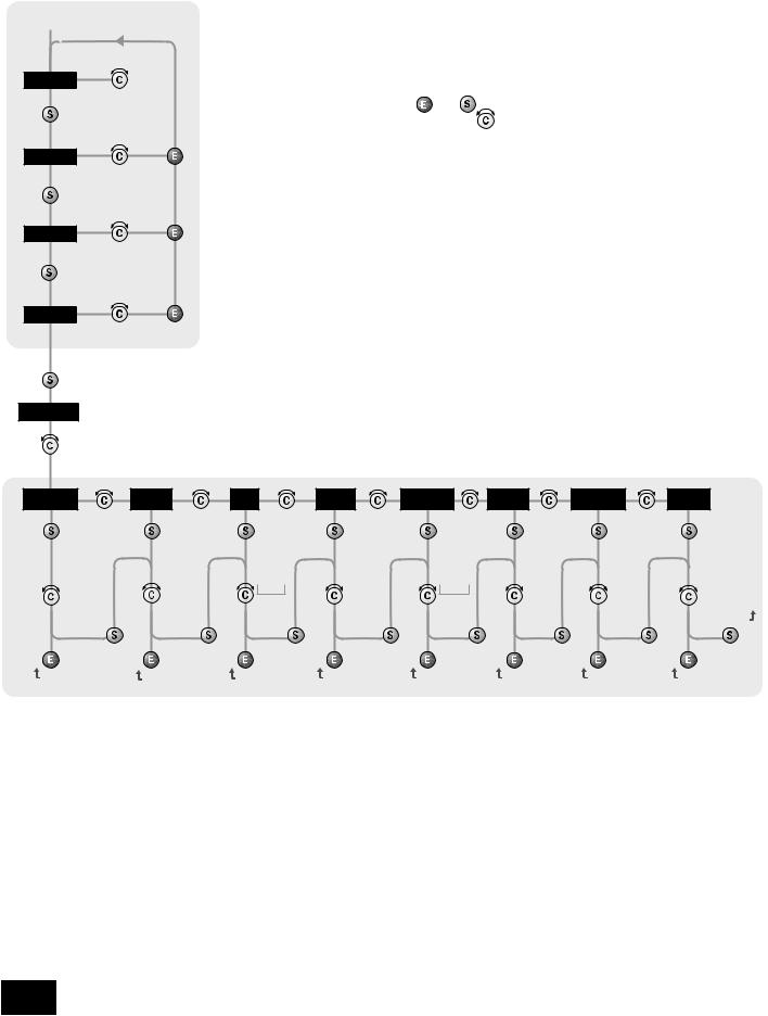
Setting up your A90 integrated amplifier
ARCAM A90 ‘Switch on’ state |
Introduction |
|
|
|
Adjusting listening settings |
|||||
The A90 allows you to adjust listening settings to |
The default display mode is VOLUME, where the |
|||||||||
|
|
|||||||||
|
|
suit your taste, and to customise various features |
control knob is used to adjust sound level. |
|||||||
DOWN |
UP |
of the amplifier to fit your system. Use this diagram |
Press SELECT to enter edit mode and cycle |
|||||||
to help you navigate through the settings available. |
||||||||||
through the other sound settings: BALANCE, |
||||||||||
VOLUME |
|
|||||||||
|
The ENTER and SELECT buttons are represented |
BASS and TREBLE. When a setting is selected, |
||||||||
adjust |
|
|||||||||
|
in the diagram by the symbols |
and |
|
adjust it with the control knob. Press ENTER to fix |
||||||
|
|
|
||||||||
|
|
respectively. The Control knob is shown as |
. |
the change you have made and return to default |
||||||
LEFT |
RIGHT |
|
|
|
|
|
(volume) mode, or press SELECT again to move to |
|||
BALANCE |
|
|
|
|
|
|
the next setting. |
|
||
adjust |
|
|
|
|
|
|
Customising amplifier settings |
|||
|
|
|
|
|
|
|
||||
|
|
|
|
|
|
|
Press SELECT until the display shows |
|||
–dB |
+dB |
|
|
|
|
|
‘CUSTOMISE->’. Now rotate the Control knob to |
|||
BASS |
|
|
|
|
|
|
choose which setting you wish to alter. Press |
|||
|
|
|
|
|
|
SELECT to adjust the chosen setting with the |
||||
adjust |
|
|
|
|
|
|
||||
|
|
|
|
|
|
|
Control knob. |
|
||
|
|
|
|
|
|
|
Press ENTER to confirm the adjustment or press |
|||
–dB |
+dB |
|
|
|
|
|
SELECT to confirm the adjustment and move on to |
|||
TREBLE |
|
|
|
|
|
|
the next item. |
|
||
adjust |
|
|
|
|
|
|
Press ENTER twice to leave the Customise menu. |
|||
Customize -> |
|
|
|
|
|
|
|
|
|
|
choose |
|
|
|
|
|
|
|
|
|
|
setting |
|
|
|
|
|
|
|
|
|
|
Volume |
VOLUME |
INPUT |
TONE |
Processor |
WELCOME |
PHONO/AUX |
RESTORE |
|||
Resolution |
DISPLAY |
TRIMS |
CONTROL |
mode |
MESSAGE |
TEXT |
SETTINGS |
|||
edit |
edit |
edit |
edit |
edit |
edit |
|
edit |
edit |
||
STANDARD |
GRAPHIC/ |
TRIM |
GLOBAL/ |
|
GAIN |
|
ARCAM |
AUX/ |
NO/YES |
|
FINE |
NUMERIC |
|
PER |
|
|
|
Amp |
PHONO |
|
|
REFERENCE |
|
|
SOURCE |
|
|
|
|
|
‘Switch on’ |
|
|
|
|
|
|
|
|
|
|
state |
|
continue |
continue |
continue |
continue |
|
continue |
|
continue |
continue |
|
|
Volume |
Volume |
Input |
Tone |
|
Processor |
Welcome |
Phono/Aux |
Restore |
||
resolution |
display |
trims |
control |
|
mode |
message |
text |
settings |
||
Volume Resolution – Standard, fine or
Reference. ‘Standard’ and ‘Fine’ represent different levels of volume control sensitivity. The ‘Reference’ setting gives absolute increments in 0.5dB steps.
Volume display mode – graphic or numeric shows the volume either as a bar graph or as a number. If Volume resolution is set to ‘Reference’ a numeric volume display shows the actual decibel figure.
Input Trims – use the source select buttons and Control knob to set input trims for each source. Input trims are used to compensate for variations in output levels of different source equipment.
A90/P90
8
Tone Control – Global or Per source. This specifies the scope of changes for ‘Bass’ and ‘Treble’ tone settings. The default setting is ‘Global’ which affects all inputs equally. ‘Per source’ allows you to set tone controls for individual inputs: once set, the amplifier remembers tone settings for each input.
Processor Mode – This mode enables you to adjust the gain of the amplifier. The amplifier can then be used to drive the front left and right speakers in a surround sound system when fed from a separate processor. You can then
control the volume of the entire system using the processor, feeding the sound into the TAPE input. Set the gain to match the amplifiers that drive your other loudspeakers.
Welcome message – You can change the power on Welcome message from ‘Arcam INTEGRATED AMP’ to display your name, postcode, etc. When customising the message, use the UP and DOWN buttons to select the cursor position and the Control knob to change the letter.
Phono/Aux Text – If you have had the optional Phono module added, choose ‘Phono’ so this word is displayed when the input is selected. The default is ‘Aux’.
Restore Settings – this restores all amplifier settings, including Input trims and the Welcome message, to their factory defaults.
Using the remote control
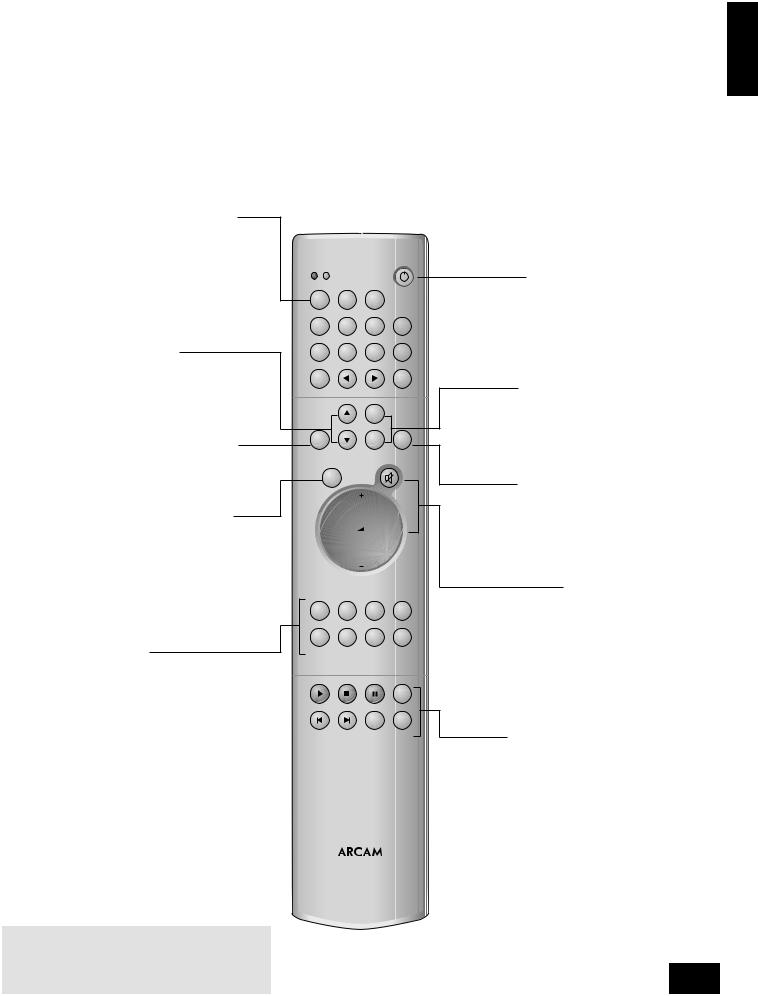
CR-389 Remote Control
The CR-389 remote control gives access to all functions available on the front panel of the A90. It also has controls to operate Arcam CD players, AM/FM tuners and DAB tuners. The remote control transmits Philips RC-5 type codes.
TUNER
These buttons are used to control tuner functions.
Note that the FM/DAB lights indicate into which mode you are switching the remote control. The lights only illuminate for five seconds to conserve battery power. If neither light is illuminated this does not mean that the remote control is not working!

 (UP and DOWN)
Perform the same function as the 
 buttons on the front panel (see page 6).
ENTER
Performs the same function as the ENTER button on the front panel (see page 8).
SELECT
Performs same function as the SELECT button on the front panel. It allows you to use the remote’s volume switch in the same way you use the control dial on the front panel – to adjust various amplifier settings (see page 8).
Note that pressing + corresponds to turning the Control knob clockwise, – to anticlockwise.
Source selection buttons
These operate in the same way as the source selectors on the front panel of your integrated amplifier.
NOTE: Remember to install the two supplied AAA batteries before trying to use your remote control!
Do not place anything in front of the IR receiver on the left of the A90, or the remote control may not work.
TUNER
FM DAB
FM |
MENU |
DISP |
|
DAB |
|
||
|
|
|
|
1-9 |
2-10 |
3-11 |
4-12 |
5-13 |
6-14 |
7-15 |
8-16 |
MODE |
|
|
BAND |
|
|
SP1 |
|
ENTER |
|
SP2 |
DISP |
SELECT
PHONO |
AUX |
TUNER |
CD |
AV |
TAPE |
VCR |
DVD |
|
AMPLIFIER |
|
|
|
|
|
RPT |
|
|
PROG |
INFO |
CD
CR-389
English
Power/Standby
Toggles the amplifier between standby mode and full power mode. The power indicator light next to the power button on the front panel is red if the amplifier is in standby, amber while the amplifier is powering up (this only takes a few seconds) and green when the amplifier is powered up.
SP1 and SP2
These buttons allow you to select and deselect the main (SP1) and secondary (SP2) sets of speakers attached to your amplifier (see page 6).
DISP (display)
Cycles through the settings ‘Bright’, ‘Off’ and ‘Dim’. Turning the display ‘Off’ generally gives a slight improvement in sound quality.
Volume and (mute)
Press + to increase volume or – to decrease the output volume of the amplifier.
Press to mute the speaker connections and preamp outputs. Both tape outputs and the headphone socket remain active. Mute is disabled either by pressing
 again, or by adjusting the volume.
You can use the remote’s volume control in conjunction with the SELECT button to adjust balance, tone and amplifier settings.
CD controls
These offer basic controls of Arcam CD players
A90/P90
9

Installation: P90 power amplifer
Optional Third Channel Module
– provides a third 90W channel suitable for Home Cinema or multi-channel audio use.
Connecting to power, loudspeakers and other equipment
Follow the installation instructions for the integrated amplifier on pages 4 and 5.
AUDIO IN – Connect this input to the output sockets of your preamplifier or the PRE OUT sockets of an integrated amplifier.
MONO LINK – The power amplifier can be adapted to provide two mono loudspeaker outputs from a single input. Pull out the link supplied and use it to connect the L and R AUDIO OUT sockets together. Using one power amplifier per loudspeaker will enable you to bi-amplify bi-wireable loudspeakers.
This is particularly beneficial for top quality stereo installations with a separate pre-amplifier, or where amplifiers are provided for the left, centre and right channel loudspeakers in a five speaker Dolby Pro Logic or Dolby Digital system.
Contact your Arcam dealer for more information.
“Daisy chaining” – The power amplifier can be connected to further power amplifiers to drive more speakers (e.g. those in other rooms or tri-amplified speakers, etc).
Connect the extra power amplifier inputs to the AUDIO OUT sockets on the power amplifier, left to left, right to right.
Remote switching
By making a connection from the REMOTE IN socket of the P90 power amplifier to the TRIG OUT socket of the A90 integrated amplifier, you can use the A90 to switch the power amplifier on and off. If configured in this way, the front panel POWER button of the A90 (or the POWER/STANDBY button on the remote control) switches both amplifiers on and off together. This facility allows you to conceal the power amplifier yet still control it.
The connecting cable required is a 3.5mm to 3.5mm jack lead (stereo or mono) and it is possible to connect several power amplifiers to an A90 by ‘daisy chaining’ from TRIG OUT of one P90 into the REMOTE IN of the next.
Three channel option
The power amplifier can be upgraded from stereo to three channels by adding a Third Channel Module: in this case, the model is designated P90/3.
The module offers extra loudspeaker terminals together with a third set of AUDIO IN and OUT phono sockets and converts the P90 into a 3 x 90W (RMS per channel into 8Ω) amplifier suitable for Home Cinema or multi-channel audio use.
Contact your Arcam dealer for further details.
A90/P90
10
Using your P90 power amplifier
POWER (and power indicator light)
Switches the unit on and off. The light indicates the status of the amplifier.
When you switch your amplifier on, the light glows amber for a few seconds, during which time the speakers are disconnected. The light changes to green when the amplifier is ready for use. A red light means the amplifier is in standby mode.
The power light may flash if a fault has occurred, with the colour of the flashing light indicating the nature of the fault:
green – a D.C. offset fault has occured
amber – a thermal fault has occured (the amplifier is too hot)
red – a short circuit fault has occured (this can happen if the speaker cables are not connected correctly and are making contact with each other or with the chassis)
red and amber – more than one fault has occured. Except for a thermal fault, if one of the above faults is detected by your amplifier the unit waits for six seconds before checking to see if the fault has cleared. If the fault clears within six seconds, then the unit continues operation; otherwise the unit shuts itself down. In the case of a thermal fault, the unit waits until its sensor temperature lowers before resuming operation.
If the amplifier has shut itself down, you should unplug the amplifier and leave it for a few minutes before reconnecting. If the fault cannot be cleared, unplug your amplifier and contact your Arcam dealer.
English
P90 POWER AMPLIFIER
SP1 |
SP2 |
POWER |
SP1 and SP2
These buttons allow you to select and deselect the main (SP1) and secondary (SP2) sets of speakers attached to your amplifier. An indicator light shows which set of speakers are currently selected.
NOTE: If both lights are out the amplifier will appear not to work, as all speakers are switched off.
A90/P90
11
Bi-wiring and bi-amping loudspeakers
Before you start |
Bi-amping your system |
WARNING: Do not make any connections to your amplifier while it is switched on or connected to the mains supply.
Before switching on please check all connections thoroughly, making sure bare wires or cables are not touching the amplifier in the wrong places (which could cause short circuits) and you have connected positive
(+) to positive and negative (–) to negative.
Always ensure that the volume control on your amplifier is set to minimum before starting these procedures.
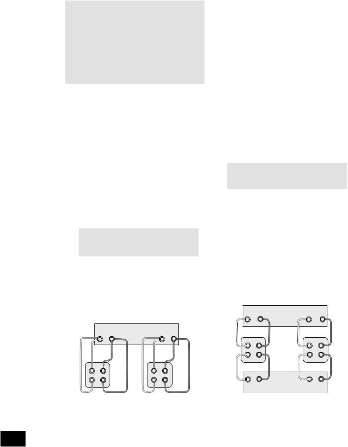
Bi-wiring your loudspeakers
Bi-wiring improves the sound of your system because it divides the high and low frequency signal currents into separate speaker cables. This avoids signal distortions arising from the high and low frequency currents interacting with one another within a single cable, as in conventionally wired systems.
You will need:
Speakers – with four input terminals each: these will be marked HF (High Frequency) and LF (Low Frequency).
Loudspeaker cables – two pairs of cables per loudspeaker (which may be joined at the amplifier end if your amplifier has only one pair of output terminals per channel), or a suitably terminated cable set.
How to bi-wire loudspeakers
1.Remove the terminal links on the rear of your loudspeakers
WARNING: This step is essential or damage to your amplifier may result which is not covered under warranty.
2.Connect the cables as shown in the diagram below, ensuring correct polarity at all times.
|
|
Arcam A90 amplifier |
|
|
|
|
+ |
– |
|
+ |
– |
|
|
R |
|
|
L |
+ |
HF |
– Right |
+ |
HF |
– Left |
+ |
LF |
– speaker |
+ |
LF |
– speaker |
The performance of your system can be further enhanced over that achieved with bi-wiring, by extending the principle one stage further to include separate amplification for the low and high frequency drive units in each loudspeaker enclosure.
Connect the integrated amplifier to the high frequency (HF) terminals and connect the power amplifier to the low frequency (LF) terminals.
You will need:
Speakers – with four input terminals each (as with bi-wiring): these will be marked HF (High Frequency) and LF (Low Frequency).
Two amplifiers – one of these would be the A90 and the other an Arcam power amplifier (e.g. P90).
Loudspeaker cables – two pairs of cables per loudspeaker or a suitably terminated cable set.
Interconnect cables – one pair of high quality interconnect cables.
How to set up a bi-amped system
1.Remove the terminal links on the rear of your loudspeakers.
WARNING: This step is essential or damage to your amplifier may result which is not covered under warranty.
2.Connect the cables as shown in the diagram below, ensuring correct polarity at all times.
3.Use the interconnect cables to connect the PRE OUT sockets of the A90 to the corresponding AUDIO IN sockets of the power amplifier.
+ |
– |
Arcam A90 amplifier |
+ |
– |
|
R |
|
L |
|
+ |
– |
|
+ |
– |
Right |
HF |
|
HF |
Left |
speaker |
LF |
– |
LF |
speaker |
|
|
|||
|
– |
|
|
|
+ |
– |
|
+ |
– |
|
R |
Arcam P90 power amplifier |
L |
|
|
|
|
|
Bi-wiring using one set of connections on amplifier |
Recommended bi-amping configuration |
A90/P90
12

Remote-control codes
The following table gives the IR-commands accepted by the
A90.
Power commands
Command |
Decimal Code |
Power toggle |
16–12 |
Power-on |
16–123 |
Power-off |
16–124 |
Source selection commands |
|
Command |
Decimal Code |
PHONO select |
16–1 |
AV select |
16–2 |
TUNER select |
16–3 |
DVD select |
16–4 |
TAPE select |
16–5 |
VCR select |
16–6 |
CD select |
16–7 |
AUX select |
16–8 |
Volume control commands |
|
Command |
Decimal Code |
Mute |
16–13 |
Volume up |
16–16 |
Volume down |
16–17 |
Menu navigation commands |
|
Command |
Decimal Code |
UP |
16-32 |
DOWN |
16-33 |
SELECT |
16–37 |
ENTER |
16–87 |
Speaker control commands |
|
Command |
Decimal Code |
Speaker 1 toggle |
16–35 |
Speaker 2 toggle |
16–39 |
Speaker 1 on |
16–43 |
Speaker 1 off |
16–44 |
Speaker 2 on |
16–45 |
Speaker 2 off |
16–46 |
Display control commands |
|
Command |
Decimal Code |
Display |
16–59 |
Note that the A90 also responds to code 20–53 (the Play command for an Arcam CD player). The A90 swiches automatically to CD input on receiving this command.
English
A90/P90
13

Service information
Before returning your amplifier for service, please check the following:
Sound cuts out for no reason
If the temperature of the internal heatsink rises above a safe level, then a thermal cutout inside the amplifier will operate.
The power indicator on the front panel flashes and the protection system temporarily removes the power to the speakers. The system resets itself as the heatsink cools down.
With two pairs of low impedance speakers connected, overloads are more likely. Overloading the amplifier may cause it to shut down because of overheating.
Note that because of the high output voltage from a CD player, it is possible to drive the A90 at full power even though the volume is not set at maximum.
Amplifier does not switch back on
The A90 and P90 amplifiers have a protection mechanism which is activated if you switch the unit on immediately after turning it off. If this mechanism activates, wait 30 seconds then try again.
Technical specifications
|
A90 |
P90 |
Continuous power output, per channel |
|
|
Both channels, 8Ω, 20Hz–20kHz |
90W |
90W |
Single channel, 4Ω, 1kHz |
150W |
150W |
Distortion, 8Ω, 80% power, 1kHz |
0.005% |
0.005% |
Inputs |
|
|
Phono cartridge (optional module) |
|
|
input sensitivity, MM |
2.5mV |
|
input sensitivity, MC |
250µV |
|
Line and tape inputs |
|
|
Nominal sensitivity |
250mV |
700mV |
Input impedance |
22kΩ |
22kΩ |
Signal/noise ratio (CCIR) |
105dB |
112dB |
Tone controls, max. boost/cut |
±12dB |
|
Preamplifier outputs |
|
|
Nominal output level |
700mV |
|
Output impedance |
<50Ω |
|
General |
|
|
Power consumption (maximum) |
800VA |
800VA (950VA for P90/3) |
Dimensions W x D x H (including feet) |
435 x 340 x 100mm |
435 x 320 x 100mm |
Weight (net) |
9kg |
9.5kg (10.5kg for P90/3) |
Weight (packed) |
10.5kg |
11kg (12kg for P90/3) |
Supplied accessories |
mains lead |
mains lead |
|
CR-389 remote control |
|
|
2 x AAA batteries |
|
E&OE |
|
|
A90/P90
14
Continual improvement policy
Arcam has a policy of continual improvement for its products. This means that designs and specifications are subject to change without notice.
NOTE: All specification values are typical unless otherwise stated.

Guarantee
Worldwide Guarantee
This entitles you to have the unit repaired free of charge, during the first two years after purchase, at any authorised Arcam distributor provided that it was originally purchased from an authorised Arcam dealer or distributor. The manufacturer
can take no responsibility for defects arising from accident, misuse, abuse, wear and tear, neglect or through unauthorised adjustment and/or repair, neither can they accept responsibility for damage or loss occurring during transit to or from the person claiming under the guarantee.
The warranty covers:
Parts and labour costs for two years from the purchase date. After two years you must pay for both parts and labour costs.
The warranty does not cover transportation costs at any time.
Claims under guarantee
This equipment should be packed in the original packing and returned to the dealer from whom it was purchased, or failing this, directly to the Arcam distributor in the country of residence.
It should be sent carriage prepaid by a reputable carrier -– NOT by post. No responsibility can be accepted for the unit whilst in transit to the dealer or distributor and customers are therefore advised to insure the unit against loss or damage whilst in transit.
For further details contact Arcam at:
Arcam Customer Support Department,
Pembroke Avenue, Waterbeach, CAMBRIDGE
CB5 9QR, England.
Telephone: |
+44 (0)1223 203200 |
Fax: |
+44 (0)1223 863384 |
Email: |
support@arcam.co.uk |
Problems?
If your dealer is unable to answer any query regarding this or any other Arcam product please contact Arcam Customer Support on +44 (0) 1223 203200 or write to us at the above address and we will do our best to help you.
English
On-line registration
You can register your Arcam product on line at:
www.arcam.co.uk
A90/P90
15

Consignes de sécurité
CAUTION |
ATTENTION |
|
|
RISK OF ELECTRIC |
RISQUE DE CHOC ELECTRIQUE |
SHOCK DO NOT OPEN |
NE PAS OUVRIR |
|
|
ATTENTION : Pour diminuer les risques de choc électrique, ne pas retirer le couvercle (ou l’arrière). L’intérieur ne contient aucune pièce nécessitant un entretien de la part de l’utilisateur. Pour l’entretien, se référer au personnel qualifié de service après-vente.
ATTENTION : Pour diminuer les risques de choc électrique, ne pas exposer cet appareil à la pluie ou à l’humidité.
Le symbole d’un éclair avec une pointe à l’intérieur d’un triangle équilatéral est destiné à alerter les utilisateurs d’un ‘voltage dangereux’ non isolé à l’intérieur de l’amplificateur, d’une puissance suffisante pour constituer un risque de choc électrique.
Le point d’exclamation à l’intérieur d’un triangle équilatéral est destiné à alerter les utilisateurs de la présence d’instructions d’utilisation ou d’entretien (maintenance) importantes au sein de la documentation fournie avec ce produit.
ATTENTION : Au Canada et aux Etats-Unis, pour éviter tout choc électrique, faites correspondre la partie large de la prise mâle à la fente large de la prise femelle et l’insérer jusqu’au fond de la prise femelle.
Normes de sécurité
Cet appareil a été conçu et fabriqué conformément aux normes de qualité et de sécurité les plus strictes. Vous devez cependant observer les précautions suivantes lors de son installation et de son utilisation :
1. Avertissements et consignes
Il est conseillé de lire les consignes de sécurité et d’utilisation avant de mettre le lecteur en marche. Conservez ce manuel pour pouvoir vous y référer par la suite et respectez scrupuleusement les avertissements y figurant ou ceux indiqués sur l’appareil lui-même.
2. Eau et humidité
L’installation d’un appareil électrique à proximité d’une source d’eau présente de sérieux risques. Ne pas utiliser l’appareil à proximité d’un point d’eau - par exemple près d’une baignoire, d’un lavabo, d’un évier, dans une cave humide ou à côté d’une piscine, etc.
3. Chute d’objets ou infiltration de liquides
Veiller à ne pas laisser tomber d’objets ni couler de liquides à travers l’une des ouvertures de l’enceinte. Ne pas placer d’objet contenant du liquide sur l’appareil.
4. Ventilation
Eviter de placer l’appareil sur un lit, un canapé, un tapis ou une surface similaire instable, ou dans une bibliothèque ou un meuble fermé, qui risquerait de ne pas être ventilé correctement. Pour permettre une ventilation appropriée, il
est conseillé de prévoir au minimum un espace de 50 mm de chaque côté et au-dessus de l’appareil.
5. Exposition à la chaleur
Ne pas placer l’appareil près d’une flamme nue ou de tout dispositif produisant de la chaleur (radiateur, poêle ou autre). Cette règle s’applique également aux amplificateurs.
6. Conditions climatiques
L’appareil est conçu pour fonctionner dans des climats modérés.
A90/P90
16
7. Etagères et supports
Utiliser uniquement des étagères ou des supports pour équipements audio. Si l’appareil est monté dans un rack de transport, le déplacer avec précaution, pour éviter tout risque de chute.
8. Nettoyage
Débrancher l’appareil du secteur avant de le nettoyer.
Pour le nettoyage, n’utiliser qu’un chiffon doux, humide et non pelucheux. N’utiliser ni diluant pour peinture, ni solvant chimique.
L’emploi de sprays ou de produits de nettoyage pour meubles est déconseillé, car le passage d’un chiffon humide risquerait de laisser des marques blanches indélébiles.
9. Alimentation
Brancher l’appareil uniquement à une source d’alimentation du type mentionné dans le manuel d’utilisation ou indiqué sur l’appareil lui-même.
10. Protection des câbles d’alimentation
Veiller à ce que les câbles d’alimentation ne se trouvent pas dans un lieu de passage ou bloqués par d’autres objets. Cette règle s’applique plus particulièrement aux prises et câbles d’alimentation et à leurs points de sortie de l’appareil.
11. Mise à la masse
S’assurer que l’appareil est correctement mis à la masse.
12. Câbles haute tension
Eviter de monter l’antenne extérieure de l’appareil à proximité de câbles haute tension.
13. Périodes de non-utilisation
Si l’appareil possède une fonction de mise en veille, un léger courant continuera de circuler lorsqu’il sera réglé sur ce mode. Débrancher le cordon d’alimentation de la prise secteur si l’appareil doit rester inutilisé pendant une période prolongée.
14. Odeur suspecte
Arrêter et débrancher immédiatement l’appareil en cas de fumée ou d’odeur anormale. Contacter immédiatement votre revendeur.
15. Entretien
Ne pas tenter d’effectuer d’autres opérations que celles mentionnées dans ce manuel. Toute autre opération d’entretien doit être effectuée par un personnel qualifié.
16. Entretien par un personnel qualifié
L’appareil doit être entretenu par un personnel qualifié lorsque :
A.le cordon d’alimentation ou la prise a été endommagé(e), ou
B.des objets sont tombés ou du liquide a coulé dans l’appareil, ou
C.l’appareil a été exposé à la pluie, ou
D.l’appareil ne semble pas fonctionner normalement ou présente des altérations dans son fonctionnement, ou
E.l’appareil est tombé ou l’enceinte a été endommagée.
Respect des consignes de sécurité
Cet appareil a été conçu pour répondre à la norme internationale de sécurité électrique EN60065.

Utilisation de ce manuel
Ce manuel a été rédigé pour fournir toutes les informations dont vous avez besoin pour installer, brancher, régler et utiliser l’amplificateur intégré Arcam A90 ou l’amplificateur de puissance P90. L’amplificateur A90 est d’abord décrit, puis le P90. Il décrit également le boîtier de télécommande CR-389 fourni avec l’amplificateur intégré A90.
Si votre ou vos amplificateurs ont été installés et réglés par un revendeur Arcam agréé, passez directement aux sections décrivant l’utilisation de cet appareil.
Sécurité
Les consignes de sécurité se trouvent à la page 16 de cette manuel.
Bien que bon nombre d’entre elles fassent appel au simple bon sens, il est conseillé de les lire pour votre propre sécurité et pour éviter d’endommager l’appareil.
Table des matières |
|
Consignes de sécurité............................................ |
16 |
Normes de sécurité................................................. |
16 |
Respect des consignes de sécurité........................... |
16 |
Utilisation de ce manuel ......................................... |
17 |
Sécurité.................................................................. |
17 |
Installation: Amplificateur intégré A90 .................... |
18 |
Mise en place de l’appareil ....................................... |
18 |
Branchement des haut-parleurs ................................ |
18 |
Branchement sur une source d’alimentation |
|
électrique................................................................ |
18 |
Branchement sur d’autres appareils .......................... |
19 |
Utilisation de l’amplificateur intégré A90................. |
20 |
Commandes du panneau avant................................. |
20 |
Enregistrement........................................................ |
21 |
Réglage de l’amplificateur intégré A90................... |
22 |
Utilisation de la télécommande............................... |
23 |
Télécommande CR-389............................................ |
23 |
Installation : amplificateur de puissance P90 .......... |
24 |
Branchement sur la source d’alimentation, |
|
des haut-parleurs et sur d’autres appareils................. |
24 |
Arrêt et mise en marche à l’aide de |
|
la télécommande..................................................... |
24 |
Option triple canal.................................................... |
24 |
Utilisation de l’amplificateur de puissance P90........ |
25 |
Bi-câblage et bi-amplification des haut-parleurs...... |
26 |
Avant de commencer............................................... |
26 |
Bi-câblage des haut-parleurs..................................... |
26 |
Bi-amplification du système ...................................... |
26 |
Tableau des commandes IR.................................... |
27 |
Dépannage ............................................................ |
28 |
Spécifications techniques....................................... |
28 |
Garantie ................................................................ |
29 |
Inscription en ligne................................................. |
29 |
Français
A90/P90
17

Installation: Amplificateur intégré A90
1
A90/P90
18
TRIG
OUT
REMOTE
IN
2 3 4 5 6 7 89 bkblbm bnbobp bq br
Mise en place de l’appareil |
|
|
Amplificateur Arcam A90 |
|
Poser l’amplificateur sur une surface plane et ferme. |
+ |
– |
+ |
– |
|
R |
|
L |
Eviter de l’exposer directement aux rayons du soleil ou de le placer près d’une source de chaleur ou d’humidité.
S’assurer qu’il est correctement ventilé. Ne pas le placer dans un espace clos, tel qu’une bibliothèque ou un meuble, qui risquerait d’empêcher la circulation de l’air dans les orifices prévus à cet effet.
Branchement des haut-parleurs
Les bornes rouges et noires 4qui se trouvent à l’arrière des amplificateurs servent à brancher les haut-parleurs. Vous pouvez connecter une ou deux paires de haut-parleurs à votre amplificateur, à condition que chacune ait une impèdance comprise entre 8 et 16Ω. (Si l’une ou les deux paires ont une impèdance infèrieure à 8Ω, la charge combinèe de l’amplificateur est infèrieure à 4Ω, ce qui risque de provoquer une surcharge.) La paire dèsignèe ‘haut-parleurs 1’ (SP1)
se branche sur les bornes du bas, et celle dèsignèe ‘hautparleurs 2’ (SP2) se branche sur les bornes du haut. Pour connecter une paire de haut-parleurs, utilisez les bornes SP1.
Lorsque vous reliez les bornes de l’amplificateur à celles des haut-parleurs, assurez-vous que les polaritès correspondent (branchez le ‘+’ sur le ‘+’, en gènèral rouge et le ‘–’ sur le ‘–’, en gènèral noir). Une erreur de ce branchement se traduit par un son central faible, une orientation imprècise des instruments et nuit au sens de la direction du son.
Le fil du haut-parleur peut être branchè sur l’amplificateur de deux façons :
En dènudant l’extrèmitè des fils :
1.Retirez l’isolant pour dègager environ 2 cm de conducteur (le mètal à l’intèrieur du fil) ;
2.S’il s’agit d’un conducteur multibrin, torsadez les brins en les serrant bien pour ne pas risquer qu’un brin soit en contact avec les bornes adjacentes ou le panneau arrière ;
3.Desserrez la borne en la tournant vers la gauche ;
4.Insèrez le fil torsadè dans le trou de la borne ;
5.Resserrez la borne en la tournant vers la droite. Lorsque vous faites un branchement en dènudant l’extrèmitè des fils, vèrifiez bien qu’aucun brin ne soit en contact avec les bornes adjacentes ou avec le panneau arrière. Il se produirait alors un court-circuit à la sortie de l’amplificateur, ce qui risquerait de l’endommager.
+ |
– |
+ |
– |
Câblage des hauts-parleurs
En utilisant des bornes embrochables :
1.Desserrez la borne en la tournant vers la gauche ;
2.Insèrez la cosse rectangulaire sous la borne ;
3.Resserrez la borne en la tournant vers la droite.
Branchement sur une source d’alimentation électrique
S’agit-il de la prise adéquate ?
Vérifiez que la prise livrée avec l’appareil correspond à l’alimentation et que la tension du secteur correspond au réglage prédéfini (115V ou 230V) indiqué sur le panneau arrière de l’appareil 2.
Si vous disposez d’une tension d’alimentation secteur ou d’une fiche secteur différente, consultez votre revendeur Arcam ou le service clientèle Arcam au +44 1223 203200.
Le produit doit être mis à la terre.
Câble de liaison au secteur
L’appareil est normalement livré avec une prise secteur moulée déjà montée sur le câble. Si vous devez, pour une raison quelconque, retirer la prise, jetez-la immédiatement dans un réceptacle approprié. En effet, son branchement sur la prise murale risque de provoquer une électrocution. Si vous avez besoin d’un nouveau câble de liaison au secteur, contactez votre revendeur Arcam.
Branchement
Enfoncez la fiche (prise de ligne IEC) du câble d’alimentation livré avec l’appareil dans la prise (POWER INLET) 1située à l’arrière de ce dernier. Vérifiez qu’elle est correctement enfoncée.
Introduisez la prise située à l’autre extrémité du câble dans votre prise d’alimentation secteur, et mettez cette dernière sous tension.
Loading...