

Aprilia SCARABEO 300 SPECIAL 2009 User Manual

APRILIA WOULD LIKE TO THANK YOU
for choosing one of its products. We have compiled this booklet to provide a comprehensive overview of your vehicle's quality features. Please, read it
carefully before riding the vehicle for the first time. It contains information, tips and precautions for using your vehicle. It also describes features, details
and devices to assure you that you have made the right choice. We believe that if you follow our suggestions, you will soon get to know your new vehicle
well and that it will continue to give you satisfactory service for many years to come. This booklet is an integral part of the vehicle and must be handed
over to the new owner in the event of sale.
APRILIA WIL U BEDANKEN
omdat u één van haar producten heeft gekozen. Wij hebben deze handleiding opgesteld opdat u de kwaliteiten ervan ten volle kan waarderen. Wij
raden aan om deze handleiding geheel door te lezen, voordat u met het voertuig gaat rijden. Het bevat informatie, raadgevingen en waarschuwingen
in verband met het gebruik van uw voertuig; daarnaast zal u eigenschappen, bijzonderheden en handigheidjes ontdekken die u ervan zullen overtuigen
dat u een juiste keuze heeft gemaakt. Wij zijn er zeker van dat indien u hier rekening mee zal houden, u makkelijk zal wennen aan uw nieuw voertuig,
waar u lang naar volle tevredenheid gebruik van zal kunnen maken. Deze uitgave is een integrerend deel van het voertuig, en bij verkoop van dit laatste
moet het worden overhandigd aan de nieuwe eigenaar.
SCARABEO 300 SPECIAL
Ed. 01 2009

The instructions in this booklet have been compiled primarily to offer a simple and clear guide to using the vehicle; it also describes routine maintenance
procedures and regular checks that should be carried out on the vehicle at an Aprilia Dealer or Authorised Workshop. This booklet also contains
instructions for simple repairs. Any operations not specifically described in this booklet require the use of special tools and/or particular technical
knowledge; for these operations, please take your vehicle to an Aprilia Dealer or Authorised Workshop.
De instructies in deze handleiding zijn voorbereid om vooral een eenvoudige en duidelijke leidraad te zijn voor het gebruik; men vindt eveneens de
handelingen van het klein onderhoud en van de periodieke controles die bij een Dealer of Erkende aprilia Garage moeten uitgevoerd worden. De
handleiding bevat tevens instructies voor een aantal eenvoudige herstellingen. De herstellingen die niet uitgebreid in deze uitgave zijn beschreven,
vereisen dat men over speciale gereedschappen en/of specifieke technische kennis beschikt; voor het uitvoeren van deze herstellingen raadt men aan
om zich te wenden tot een Dealer of Erkende aprilia Garage.
2

Personal safety
Persoonlijke veiligheid
Failure to completely observe these instructions will
result in serious risk of personal injury.
Safeguarding the environment
Sections marked with this symbol indicate the correct
use of the vehicle to prevent damaging the environ-
ment.
Vehicle intactness
The incomplete or non-observance of these regula-
tions leads to the risk of serious damage to the vehicle
and sometimes even the invalidity of the guarantee.
The symbols shown above are very important. They
are used to highlight those parts of the booklet that
should be read with particular care. As you can see,
each sign consists of a different graphic symbol, making it quick and easy to locate the various topics.
Before starting the engine, read this booklet thoroughly and the "SAFE RIDING" section in particular. Your
safety as well as other's does not only depend on the
quickness of your reflexes and agility, but also on how
well you know your vehicle, the state of maintenance
of the vehicle itself and your knowledge of the rules
for SAFE RIDING. For your safety, get to know your
vehicle well so as to safely ride and master it in road
traffic IMPORTANT This booklet is an integral part of
the vehicle, and must be handed to the new owner in
the event of sale.
Indien deze voorschriften niet of niet volledig worden
opgevolgd, kan dit ernstig letsel aan personen tot ge-
volg hebben.
Bescherming van
Geeft het juiste gedrag aan dat u aan moet houden
zodat het gebruik van het voertuig geen schade aan-
richt aan de natuur.
Staat van het voertuig
Indien deze voorschriften niet of niet volledig worden
opgevolgd kan dit ernstige schade aan het voertuig,
en eventueel het vervallen van deze garantie tot ge-
volg hebben.
Bovengenoemde signalen zijn erg belangrijk. Ze hebben namelijk tot doel om de delen van het boekje aan
te geven die u aandachtig door moet lezen. Zoals u
ziet, bestaat ieder teken uit een ander grafisch symbool, zodat de bijbehorende onderwerpen meteen
duidelijk kunnen worden gevonden in de verschillende delen. Vooraleer men de motor start, leest men
aandachtig deze handleiding, en vooral de paragraaf
"VEILIG RIJDEN". Uw veiligheid en die van anderen
hangt niet enkel af van uw reflexen en vlugheid, maar
ook van de kennis en de efficiëntie van het voertuig,
en van de kennis van de fundamentele regels voor het
VEILIG RIJDEN. We raden daarom aan om vertrouwd
te raken met het voertuig, zodat u zich veilig en beheersd kan bewegen in het verkeer. BELANGRIJK
Deze handleiding moet beschouwd worden als integrerend deel van het voertuig, en moet worden overhandigd bij de verkoop ervan.
3

4

INDEX
INDEX
VEHICLE......................................................................................... 7
Arrangement of the main components......................................... 9
Dashboard................................................................................... 11
Analogue instrument panel.......................................................... 13
Digital lcd display......................................................................... 18
Setting the total and trip odometers......................................... 20
Clock/date display.................................................................... 21
Key switch.................................................................................... 22
Locking the steering wheel....................................................... 23
Switch direction indicators........................................................... 24
Horn button.................................................................................. 25
Light switch.................................................................................. 25
Emergency flashing light button................................................... 26
Start-up button............................................................................. 27
Engine stop button....................................................................... 27
Fuel tank...................................................................................... 28
Power supply socket.................................................................... 29
The saddle................................................................................... 29
Identification................................................................................. 30
Rear top box opening.................................................................. 31
USE................................................................................................. 33
Checks......................................................................................... 34
Refuelling..................................................................................... 36
Tyre pressure............................................................................... 39
Shock absorber adjustment......................................................... 43
Running in.................................................................................... 46
Starting up the engine.................................................................. 48
Difficult start up............................................................................ 56
Stopping the engine..................................................................... 57
Catalytic silencer.......................................................................... 59
Stand........................................................................................... 60
VOERTUING..................................................................................... 7
Plaats van de hoofdcomponenten................................................. 9
Legenda......................................................................................... 11
Analoog instrumentenpaneel......................................................... 13
Digitaal display............................................................................... 18
Istellen van de kilometerteller en dagteller................................. 20
Weergave klok/datum................................................................. 21
Sleutelschakelaar........................................................................... 22
Inschakeling van het stuurslot.................................................... 23
Schakelaar richtingaanwijzers....................................................... 24
Drukknop claxon............................................................................ 25
Koplampschakelaar....................................................................... 25
Inschakelknop alarmlichten............................................................ 26
Startknop........................................................................................ 27
Stopschakelaar motor.................................................................... 27
Benzinetank................................................................................... 28
Stopcontact.................................................................................... 29
Het zadel........................................................................................ 29
Identificatie..................................................................................... 30
Penen van de koffer voor............................................................... 31
GEBRUIK.......................................................................................... 33
Controles........................................................................................ 34
Tanken........................................................................................... 36
Bandenspanning............................................................................ 39
Regeling van de schokdempers..................................................... 43
Inrijden........................................................................................... 46
Starten des motors......................................................................... 48
Moeilijke start................................................................................. 56
Het stilleggen van de motor........................................................... 57
Katalysator..................................................................................... 59
Standaard...................................................................................... 60
5

Suggestions to prevent theft........................................................ 62
Safe driving.................................................................................. 63
MAINTENANCE.............................................................................. 71
Engine oil level............................................................................. 72
Engine oil level check............................................................... 73
Engine oil top-up...................................................................... 76
Hub oil level................................................................................. 77
Tyres............................................................................................ 81
Spark plug dismantlement........................................................... 85
Removing the air filter.................................................................. 88
Air filter cleaning.......................................................................... 88
Cooling fluid level......................................................................... 89
Checking the brake oil level......................................................... 95
Battery......................................................................................... 99
Use of a new battery................................................................ 104
Long periods of inactivity............................................................. 105
Fuses........................................................................................... 106
Lamps.......................................................................................... 110
Front light group........................................................................... 112
Headlight adjustment............................................................... 115
Front direction indicators............................................................. 116
Rear optical unit........................................................................... 119
Rear turn indicators..................................................................... 120
Number plate light........................................................................ 120
Helmet compartment lighting bulb............................................... 121
Rear-view mirrors........................................................................ 122
Front and rear disc brake............................................................. 123
Periods of inactivity...................................................................... 127
Cleaning the vehicle.................................................................... 129
Transport..................................................................................... 133
TECHNICAL DATA......................................................................... 137
Kit equipment............................................................................... 143
PROGRAMMED MAINTENANCE.................................................. 145
Scheduled maintenance table..................................................... 146
Tips tegen diefstal.......................................................................... 62
Het veilig rijden.............................................................................. 63
ONDERHOUD................................................................................... 71
Peil van de motorolie..................................................................... 72
Controle van het peil van de motorolie....................................... 73
Het bijvullen van motorolie......................................................... 76
Oliepeil van de naaf....................................................................... 77
Banden........................................................................................... 81
Demonteren van de bougie............................................................ 85
Demonteren van het luchtfilter....................................................... 88
Reiniging van de luchtfilter............................................................. 88
Peil van de koelvloeistof................................................................ 89
Controle van het oliepeil van de remmen...................................... 95
Accu............................................................................................... 99
Inwerkingstelling van een nieuwe accu...................................... 104
Lange stilstand............................................................................... 105
Zekeringen..................................................................................... 106
Lampen.......................................................................................... 110
Voorste optische groep.................................................................. 112
Regeling van de koplamp........................................................... 115
Voorste richtingaanwijzers............................................................. 116
Achterste optische groep............................................................... 119
Achterste richtingaanwijzers.......................................................... 120
Nummerplaatlicht........................................................................... 120
Licht van de verlichting van de helmruimte.................................... 121
Achteruitkijkspiegels...................................................................... 122
Schijfrem vooraan en achteraan.................................................... 123
Stilstand van het voertuig............................................................... 127
Reinigen van het voertuig.............................................................. 129
Vervoer.......................................................................................... 133
TECHNISCHE GEGEVENS.............................................................. 137
Bijgeleverde gereedschappen....................................................... 143
GEPLAND ONDERHOUD................................................................ 145
Tabel van het geprogrammeerd onderhoud.................................. 146
6

SCARABEO 300 SPECIAL
Chap. 01
Vehicle
Hst. 01
Voertuing
7
01_01
8
1 Vehicle / 1 Voertuing
01_02
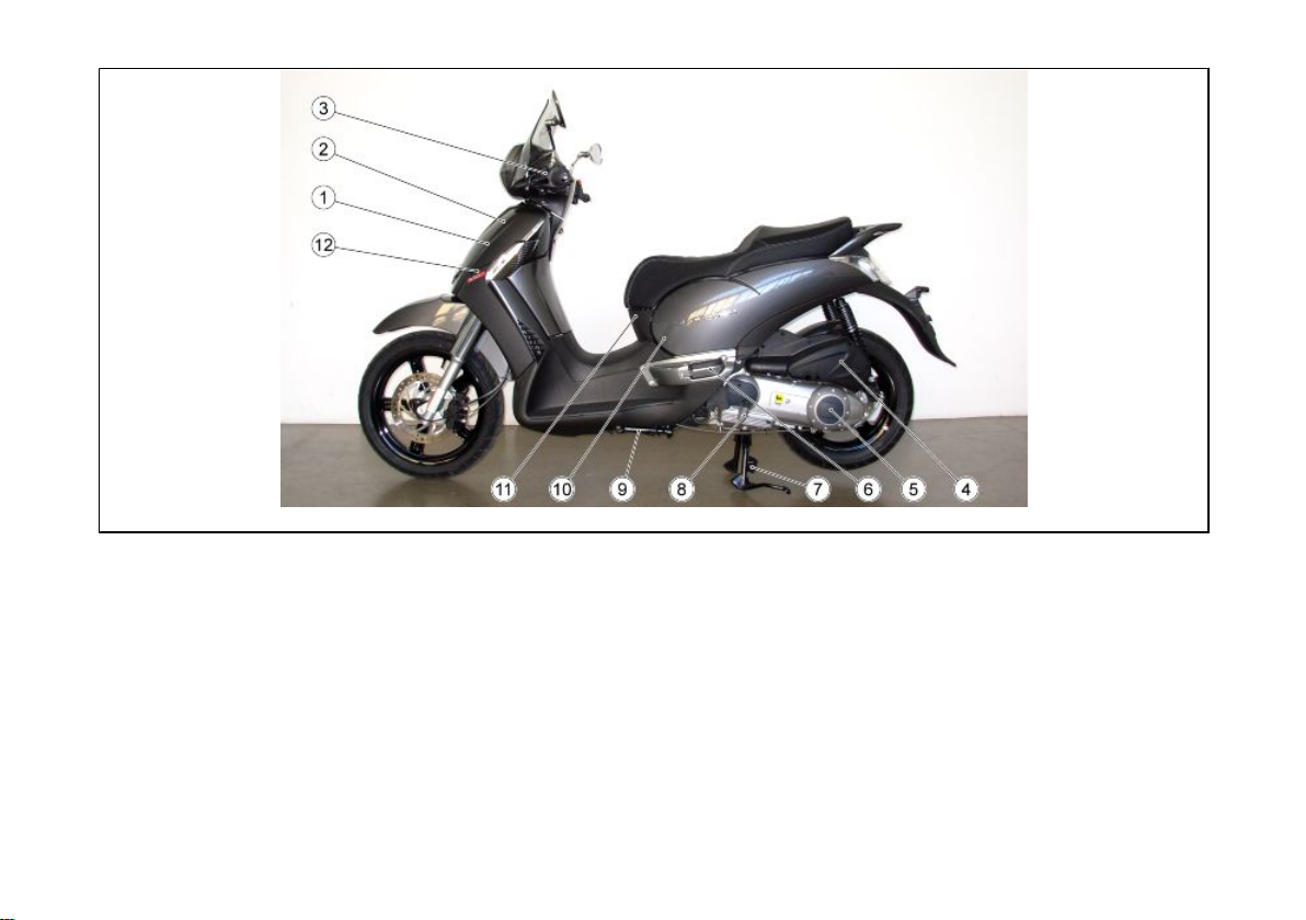
Arrangement of the main
components (01_02)
KEY:
1. Expansion tank
2. Coolant expansion tank cap
3. Rear brake fluid reservoir
4. Air filter
5. Transmission cover
6. Left passenger footrest
9
Plaats van de
hoofdcomponenten (01_02)
LEGENDE:
1. Expansievat
2. Dop van het expansievat van de koel-
vloeistof
3. Vloeistoftank van de achterrem
4. Luchtfilter
5. Transmissiedeksel
6. Linker voetensteun van de passagier

7. Centre stand
8. . Engine oil level/refill cap
9. Side stand
10. Spark plug
11. Central inspection cover
12. Horn
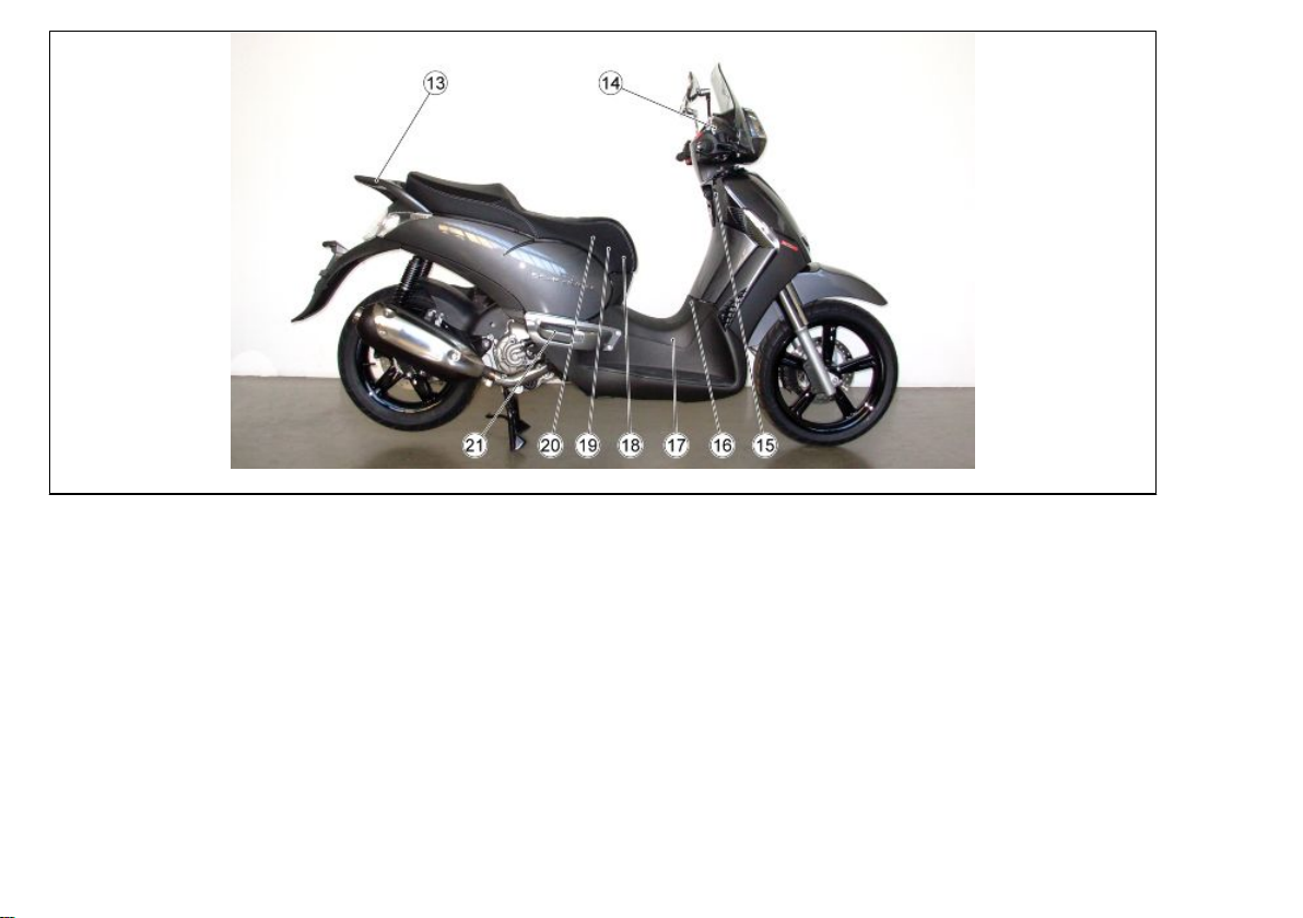
13. Passenger handgrip
14. Front brake liquid tank
15. Saddle opening switch
16. Fuel tank cap
17. Fuel tank
18. Battery
19.Secondary fusebox
20. Main fuseboxes
21. Left passenger footrest
7. Centrale standaard
8. Dop peil / bijvulling van de motorolie
9. Laterale standaard
10. Bougie
11. Centraal inspectiedeksel
12. Akoestische melder
13. Handgreep van de passagier
14. Vloeistoftank van de voorrem
15. Schakelaar voor de opening van het
zadel
16. Dop van de brandstoftank
17. Brandstoftank
18. Accu
19. Secundaire zekeringenhouders
20. Hoofdzakelijke zekeringenhouders
21. Rechter voetensteun van de passa-
gier
10
1 Vehicle / 1 Voertuing
01_03
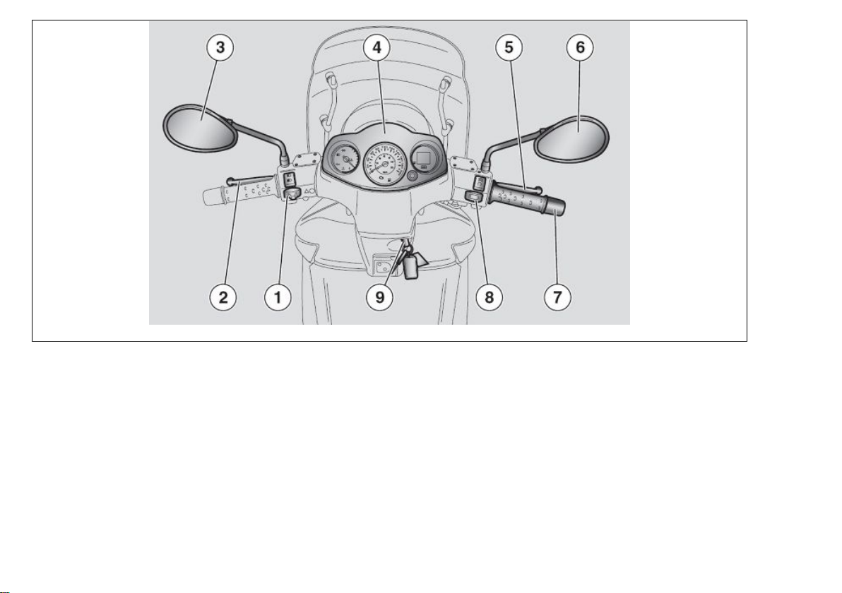
Dashboard (01_03)
KEY:
1. Electrical controls on the left-hand side
of the handlebars
2. Combined brake lever (front and rear)
3. Left rear-view mirror
4. Instruments and gauges
5. Front brake lever
11
Legenda (01_03)
LEGENDE:
1. Elektrische commando's op de linker
kant van het stuur
2. Hendel van de gecombineerde rem
(voorrem en achterrem)
3. Linker achteruitkijkspiegeltje
4. Instrumenten en indicators
5. Hendel van de voorrem
6. Right rear-view mirror
7. Throttle grip
8. Electrical controls on the right-hand
side of the handlebars
9. Ignition switch / steering lock (ON-OFF
- LOCK - OPEN GLOVE BOX - OPEN
FUEL TANK)
6. Rechter achteruitkijkspiegeltje
7. Gashandvat
8. Elektrische commando's op de rechter
kant van het stuur
9. Ontstekingsschakelaar / stuurslot ( ON
-OFF - LOCK - OPENING VAN DE OPBERGRUIMTE - OPENING VAN DE
BRANDSTOFTANK)
12
01_04

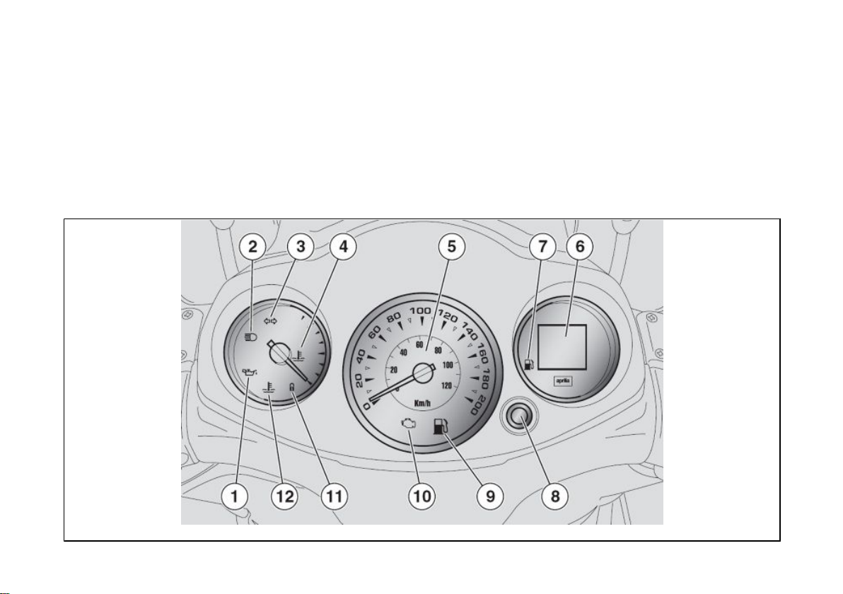
Analogue instrument panel
1 Vehicle / 1 Voertuing
(01_04)
Analoog instrumentenpaneel
(01_04)
KEY:
1. Red engine oil pressure warning light
2. Blue high-beam warning light
3. Green turn indicator warning light
4. Coolant temperature gauge
5. Speedometer
6. LCD multifunction display
7. Fuel gauge
8. MODE button
9. Yellow amber low fuel warning light
10. EFI warning light
11. Anti-theft warning light (IMMOBILIZ-
ER)
12. Red coolant high temperature warning light
LEGENDE:
1. Rode controlelamp van de druk van de
motorolie
2. Blauwe controlelamp van het groot
licht
3. Groene controlelamp van de richtingaanwijzers
4. Indicator van de temperatuur van de
koelvloeistof
5. Snelheidsmeter
6. Multifunctioneel LCD display
7. Indicator van het brandstofpeil
8. Drukknop MODE
9. Ambergele controlelamp van de
brandstofreserve
10. Controlelamp EFI
11. Controlelamp van het antidiefstalsys-
teem (IMMOBILIZER)
12. Rode controlelamp voor de hoge temperatuur van de koelvloeistof
INSTRUMENT AND GAUGE DESCRIPTION
13
BESCHRIJVING VAN DE INSTRUMENTEN EN DE INDICATORS
CAUTION
WITH THE KEY SET TO «ON» ALL THE
PRE-INSTALLED WARNING LIGHTS,
INSTRUMENT PANEL LIGHTING AND
ALL THE SEGMENTS IN DISPLAY 3
TURN ON FOR THE FIRST 3 SECONDS
FOR AN INITIAL INSTRUMENT
CHECK.
LET OP
MET DE SLEUTEL IN DE «ON» POSI-
TIE, LICHTEN ALLE VOORZIENE
CONTROLELAMPEN, DE VOLLEDIGE
VERLICHTING VAN HET DASHBOARD EN ALLE SEGMENTEN VAN
DE 3 DISPLAYS OP VOOR 3 SECONDEN, VOOR EEN BEGINCHECK VAN
HET INSTRUMENT.
Engine oil pressure warning light «1»
Turns on every time the ignition switch is
set to «ON» and the engine has not been
started, this tests LED operation. The
warning light should turn off as soon as
the engine is started.
CAUTION
IF THE WARNING LIGHT TURNS ON
WHILE THE ENGINE IS WORKING
PROPERLY, THIS MEANS THAT THE
OIL PRESSURE IN THE CIRCUIT IS
NOT ENOUGH. IF THIS OCCURS,
STOP THE ENGINE AT ONCE AND
CONTACT AN aprilia Official Dealer.
14
Controlelamp van de druk van de motorolie «1»
Deze licht elke keer op wanneer men de
onstekingsschakelaar in «ON» plaatst en
de motor niet gestart heeft, om zo een
test uit te voeren van de werking van de
LED. De controlelamp moet uitgaan wanneer de motor wordt gestart.
LET OP
WANNEER DE CONTROLELAMP OPLICHT TIJDENS DE NORMALE WERKING VAN DE MOTOR, IS DE DRUK VAN
DE MOTOROLIE IN HET CIRCUIT ONVOLDOENDE. IN DIT GEVAL LEGT
MEN ONMIDDELLIJK DE MOTOR
STIL, EN WENDT MEN ZICH TOT EEN
Officiële aprilia Dealer.
1 Vehicle / 1 Voertuing
High-beam warning light «2»
Turns on when the front headlamp highbeam bulb is activated or when the highbeam light is flashed (PASSING).
Turn indicator warning light «3»
It flashes when the turning indication is
activated
Controlelamp van het groot licht «2»
Deze licht op wanneer het lampje van het
groot licht van het voorlicht geactiveerd
is, of wanneer men het groot licht doet
knipperen (PASSING).
Controlelamp van de richtingaanwijzer «3»
Deze knippert wanneer het signaal van
verandering van richting in functie is
Coolant temperature gauge «4»
Shows the approximate temperature of
the coolant in the engine. When the needle starts to move away from the "MIN"
mark, the temperature is adequate to ride
the scooter. The normal operating temperature is reached when the needle is at
central area of the scale. If the needle
enters the red area or the warning light
turns on, stop the engine and check the
coolant level.
CAUTION
IF THE TEMPERATURE EXCEEDS
THE MAXIMUM ALLOWED «MAX»
RED AREA OF THE SCALE), THE ENGINE CAN BE SERIOUSLY DAMAGED.
15
Indicator van de temperatuur van de
koelvloeistof «4»
Duidt bij benadering de temperatuur aan
van de koelvloeistof in de motor. Wanneer de wijzer zich naar het «MIN» peil
verplaatst, is de temperatuur onvoldoende om met het voertuig te kunnen rijden.
Wanneer het wijzertje zich in de centrale
zone van de schaal bevindt, is de werkingstemperatuur normaal. Wanneer de
wijzer de rode zone bereikt of de controlelamp licht op, legt men de motor stil en
de controleert men het peil van de koelvloeistof.
LET OP
WANNEER DE MAXIMUM TOEGESTANE TEMPERATUUR WORDT OVERSCHREDEN (DE RODE ZONE «MAX»

VAN DE SCHAAL), KAN DE MOTOR
ERNSTIG WORDEN BESCHADIGD.
Speedometer «5»
Shows riding speed
Multifunction LCD display «6»
The display can show the digital clock,
odometer, trip odometer, unit of measurement, scheduled maintenance service, and fuel level.
Fuel gauge «7»
Shows the approximate fuel level in the
tank.
When the needle reaches the red area,
there are about 2 litres of fuel left. If this
occurs, refill the tank as soon as possible.
MODE button «8»
Press the MODE button to select the different functions on the digital display.
Low fuel warning light «9»
Turns on when there is a 2-litre fuel reserve in the tank.
Snelheidsmeter «5»
Duidt de rijsnelheid aan
Multifunctioneel LCD display «6»
Op het display kunnen de digitale klok,
het hodogram, het partiële hodogram, de
meeteenheid, het bereik van het geprogrammeerd onderhoud, het brandstofpeil
weergegeven worden.
Indicator van het brandstofpeil «7»
Duidt bij benadering het brandstofpeil in
de tank aan.
Wanneer de wijzer de rode zone bereikt,
blijft er ongeveer 2 liter brandstof over in
de tank. In dit geval moet men zo vlug
mogelijk tanken.
Knop MODE «8»
Wanneer op de toets MODE gedrukt
wordt, kunnen de verschillende functies
van het digitale display geselecteerd worden.
Controlelamp van de brandstofreserve «9»
Deze licht op wanneer er in de brandstoftank ongeveer 2 liter brandstof overblijft.
16

1 Vehicle / 1 Voertuing
Electronic fuel injection (EFI) warning
light "10"
Turns on for about three seconds every
time the ignition switch is set to "ON" and
the engine has not been started, this tests
the injection system operation. The warning light should turn off as soon as the
engine is started.
CAUTION
IF THE WARNING LIGHT TURNS ON
WHILE THE ENGINE IS WORKING
PROPERLY, THIS MEANS THAT
THERE IS A FAILURE IN THE ELECTRONIC FUEL INJECTION SYSTEM. IF
THIS OCCURS, STOP THE ENGINE AT
ONCE AND CONTACT AN aprilia Official Dealer.
Controlelamp van de elektronische
benzineinjectie (EFI) «10»
Deze licht elke keer op voor ongeveer
drie seconden wanneer men de ontstekingsschakelaar in «ON» plaatst en de
motor niet gestart heeft, om zo een test
uit te voeren van de werking van het injectiesysteem. De controlelamp moet uitgaan wanneer de motor wordt gestart.
LET OP
WANNEER DE CONTROLELAMP OPLICHT TIJDENS DE NORMALE WERKING VAN DE MOTOR, DUIDT DIT OP
EEN PROBLEEM VAN HET ELEKTRONISCH INJECTIESYSTEEM VAN DE
BENZINE. IN DIT GEVAL LEGT MEN
ONMIDDELLIJK DE MOTOR STIL, EN
WENDT MEN ZICH TOT EEN Officiële
aprilia Dealer.
Anti-theft warning light (immobilizer)
«11»
Only for vehicles with pre-installation.
When the motorbike engine is off, this
light flashes and functions as a theft-deterrent blinker. Confirms that the antitheft system is on.
17
Controlelamp van het antidiefstalsysteem (immobilizer) «11»
Enkel voor hiervoor voorziene voertuigen.
Als de motor uit staat, wordt een alarmerende knippering tegen diefstal weergegeven. Het bevestigt dat het antidiefstalsysteem actief is.
Coolant high temperature warning
light «12»
Turns on when the coolant temperature
gauge reaches the red area. Stop the engine at once and check the coolant level.
CAUTION
IF THE TEMPERATURE EXCEEDS
THE MAXIMUM ALLOWED FOR A
LONG TIME, THE ENGINE CAN BE SERIOUSLY DAMAGED.
Controlelamp van de hoge temperatuur van de koelvloeistof «12»
Deze licht op wanneer de indicator van
de temperatuur van de koelvloeistof de
rode zone bereikt. Leg onmiddellijk de
motor stil en controleer het peil van de
koelvloeistof.
LET OP
WANNEER DE MAXIMUM TOEGESTANE TEMPERATUUR VOOR EEN LANGE PERIODE WORDT OVERSCHREDEN, KAN DE MOTOR ERNSTIG
WORDEN BESCHADIGD.
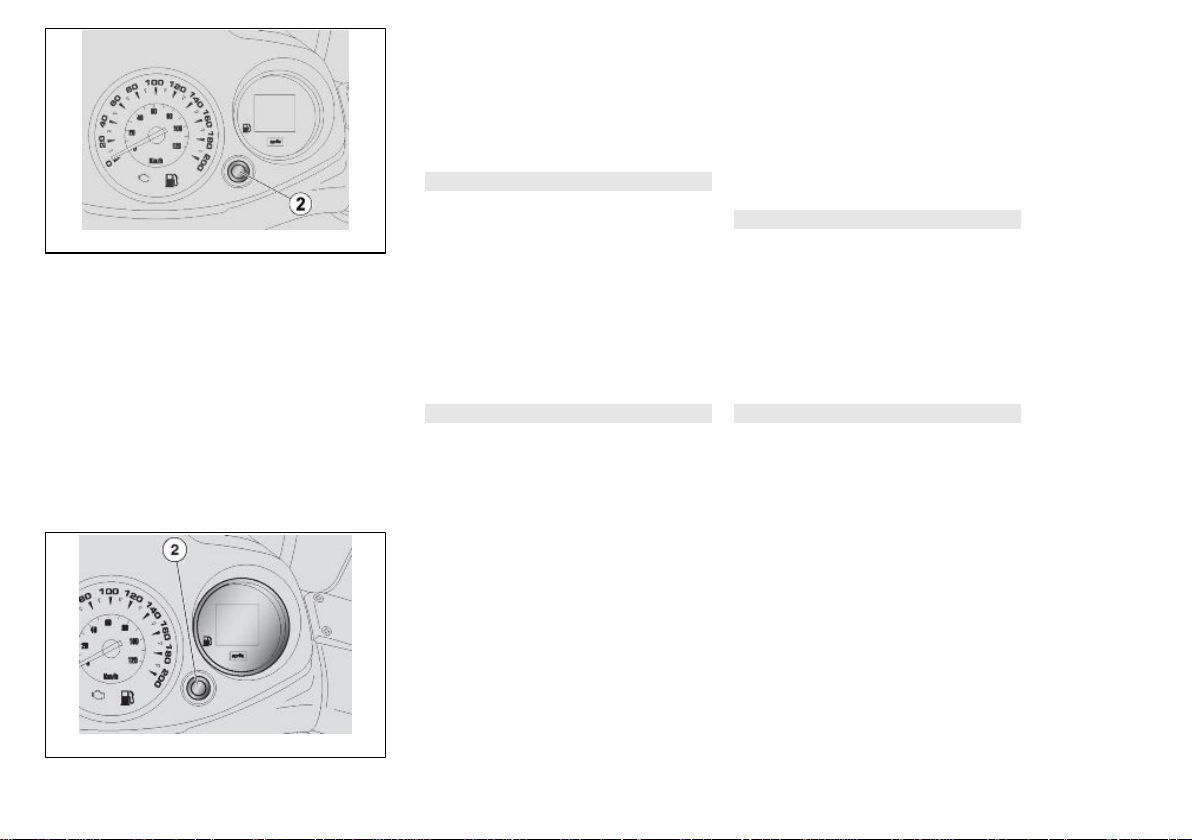
01_05
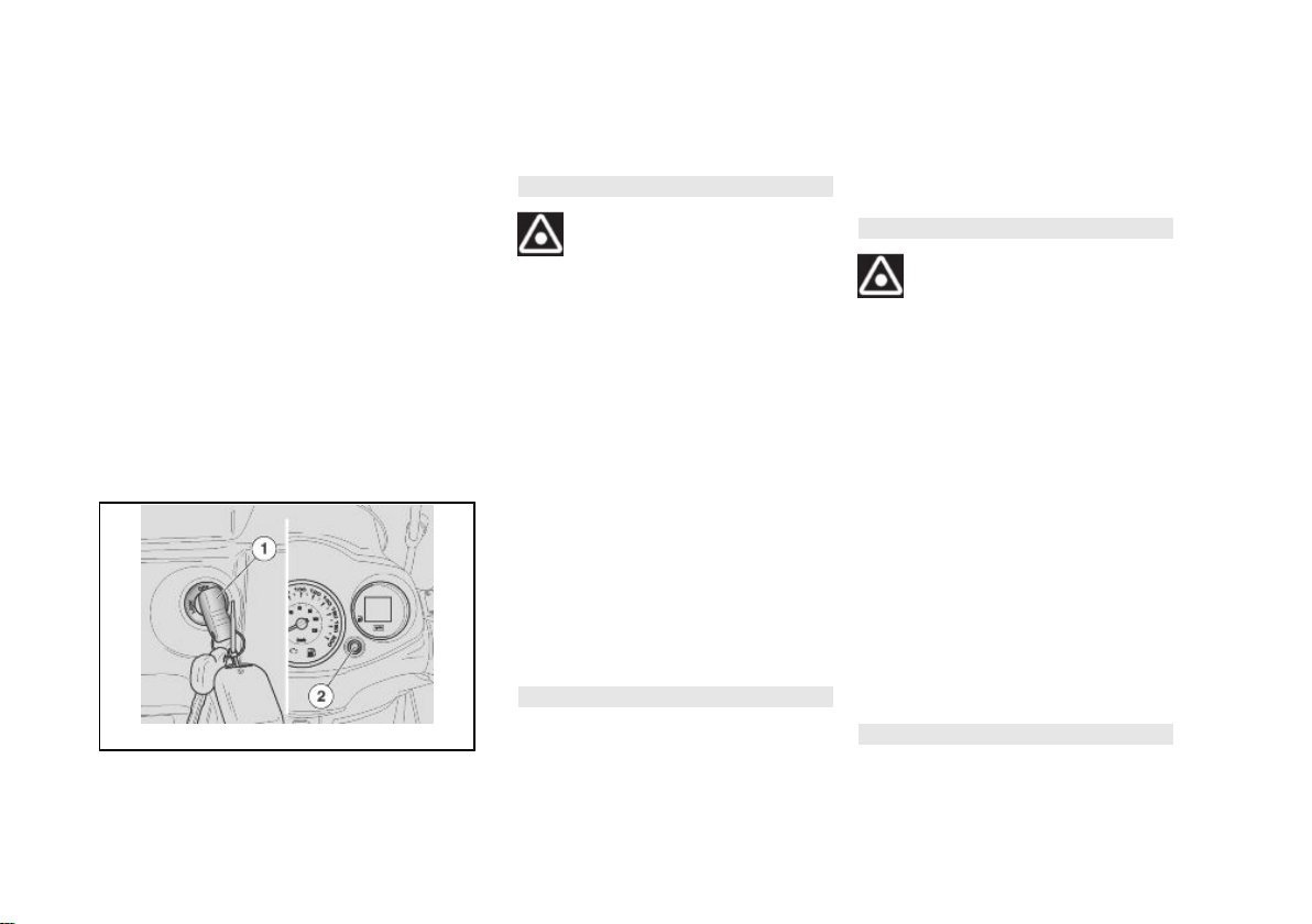
Digital lcd display (01_05,
01_06)
Turning the ignition key "1" to "ON" acti-
vates all the segments on the multifunction LCD (this checks components correct operation) and displays the last
function set after switching off the engine.
CAUTION
THE SERVICE ICON IS DISPLAYED
ON THE LCD AFTER RIDING THE
FIRST 1000 KM AND THEN AFTER EVERY 10000 KM. THE SERVICE ICON
FLASHES FOR ABOUT 5 SECONDS
AFTER THE IGNITION CHECK, 300 KM
18
Digitaal display (01_05, 01_06)
Door de ontstekingssleutel «1» in positie
«ON» te draaien, worden alle segmenten
op het multifunctioneel display geactiveerd (op deze manier wordt een controle uitgevoerd van de werking van de
onderdelen) en zal de laatste ingestelde
functie na het stilleggen van het voertuig
worden gevisualiseerd.
LET OP
DE SERVICE-ICOON OP HET LCD DIS-
PLAY LICHT OP NA DE EERSTE AFGELEGDE 1000 KM, EN VERVOLGENS ELKE 10000 KM. DE SERVICE-
1 Vehicle / 1 Voertuing
TO THE NEXT SERVICE. ONCE THE
MILEAGE FOR A SERVICE HAS BEEN
REACHED, THE ICON WILL BE
STEADILY ON UNTIL THE SERVICE IS
CARRIED OUT. IF THIS OCCURS
TAKE YOUR SCOOTER TO AN OFFICIAL APRILIA DEALER TO CARRY
OUT MAINTENANCE OPERATIONS
SPECIFIED IN THE SCHEDULED
MAINTENANCE TABLE.
ICOON BEGINT TE KNIPPEREN NA DE
ONTSTEKINGSCHECK VOOR ONGEVEER 5 SECONDEN, WANNEER ER
300 KM ONTBREKEN TOT DE KILOMETERSTAND VAN DE SERVICEBEURT. EENS DE KILOMETERSTAND
WORDT BEREIKT, BLIJFT DE ICOON
VAST OPLICHTEN TOT DE SERVICEBEURT WORDT UITGEVOERD. IN DIT
GEVAL WENDT MEN ZICH TOT EEN
OFFICIËLE APRILIA DEALER, VOOR
HET UITVOEREN VAN DE HANDELINGEN DIE WORDEN VOORZIEN IN DE
TABEL VAN HET GEPROGRAMMEERD ONDERHOUD.
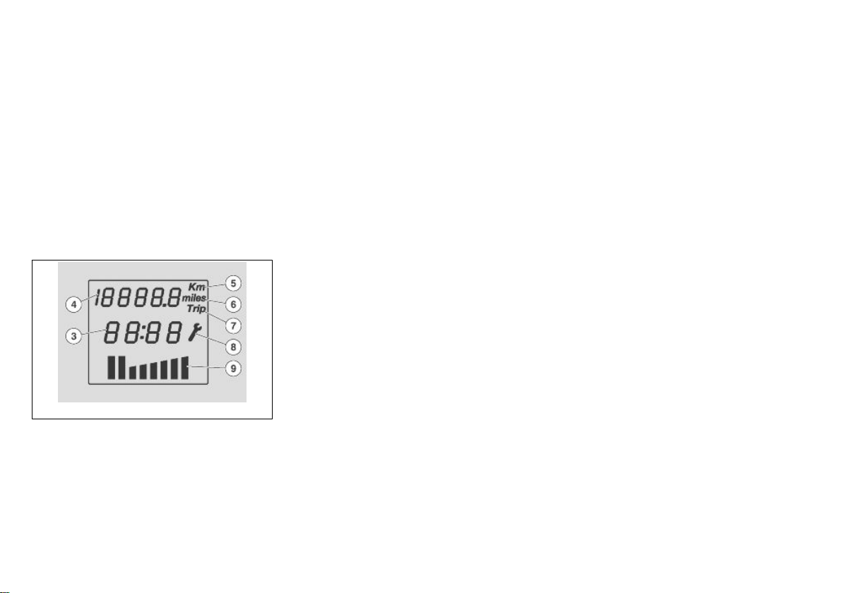
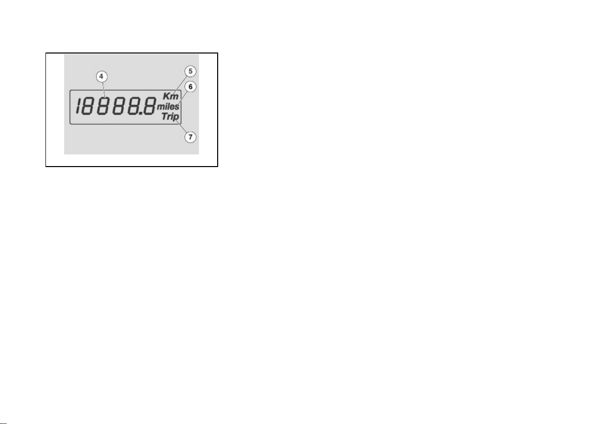
01_06
Several functions can be selected and
viewed on the display using the MODE
button "2".
The segments of the multifunction LCD
display are the following:
- digital clock "3",
- odometer indicator "4",
- unit of measure in km "5",
- unit of measure indicator in miles "6",
- trip odometer indicator "7",
- scheduled maintenance service indicator "8",
- fuel gauge "9".
19
De verschillende functies worden geselecteerd, en worden vervolgens gevisualiseerd op het display door op de MODE
knop «2».
Volgende segmenten vindt men op het
multifunctioneel LCD display:
- digitale klok «3»,
- indicator hodogram «4»,
- meeteenheid in km «5»,
- indicator meeteenheid uitgedrukt in mijl
«6»,
- indicator van het hodogram partieel
«7»,
- indicator van het bereiken van het geprogrammeerd onderhoud «8»,
- indicator van het brandstofpeil «9».
01_07
Setting the total and trip
odometers (01_07, 01_08)
DIGITAL ODOMETER
These are the segments of the digital odometer functions on the LCD display:
Icon to display trip odometer, six digits
«4», icon showing unit of measure in km
«5», icon showing unit of measure in
miles «6».
Pressing the MODE button «2» displays
in sequence the modes:
- Trip odometer
- TRIP
- Battery voltage
Istellen van de kilometerteller
en dagteller (01_07, 01_08)
DIGITAAL HODOGRAM
Volgende segmenten vindt men in de
functie van het hodogram op het LCD
display:
Icoon voor de visualisering van het hodogram partieel, zescijferige visualisering «4», icoon van de indicator van de
meeteenheid uitgedrukt in Km «5», icoon
van de indicator van de meeteenheid uitgedrukt in mijlen «6».
Door opeenvolgens op de drukknop MODE «2» te drukken, gaat men over naar
de volgende modaliteiten:
- Hodogram partieel
- TRIP
- Accuspanning
20
1 Vehicle / 1 Voertuing
01_08
RESETTING THE TRIP ODOMETER
- Press the MODE button "2" to select the
trip odometer function.
- Press and hold the MODE button "2" for
more than three seconds.
NOTE
THIS ONLY RESETS THE FUNCTION
DISPLAYED.
OPNULSTELLING VAN HET HODOGRAM PARTIEEL
- Druk op de toets MODE «2» tot de functie van het hodogram partieel wordt bereikt.
- Druk op de toets MODE «2» voor langer
dan drie seconden.
N.B.
OP DEZE MANIER WORDT ENKEL DE
GEVISUALISEERDE FUNCTIE OP NUL
GESTELD.
01_09
Clock/date display (01_09)
CAUTION
THE CLOCK WILL ONLY BE DIS-
PLAYED ONLY WHEN THE VEHICLE
HAS BEEN STARTED.
Clock adjustment:
•
Press the MODE button "2" to
select the TRIP function.
•
Press and hold the MODE button "2" for more than three seconds to activate the clock adjustment.
•
The first adjustment to be made
is the hours. Press the MODE
button "2" repeatedly to set the
desired hour.
21
Weergave klok/datum (01_09)
LET OP
DE KLOK WORDT ENKEL GEVISUA-
LISEERD WANNEER HET VOERTUIG
AANSTAAT.
Regeling van de klok:
•
Druk op de toets MODE «2» tot
de functie TRIP wordt bereikt.
•
Druk voor langer dan drie seconden op de toets MODE «2»
om de regeling van de klok te
activeren.
•
De eerste regeling die moet uitgevoerd worden, is de regeling
van de uren. Druk herhaaldelijk
op de toets MODE «2» om het
gewenste uur in te stellen.

•
Pressing the MODE button "2"
for more than three seconds activates the minutes adjustment.
•
To adjust the minutes press the
MODE button"2" until the desired minutes are displayed.
•
Once the clock has been adjusted do not press any key for
three seconds to leave this function.
NOTE
THE CLOCK CAN BE SET ONLY
WHEN THE ENGINE IS OFF OR THE
VEHICLE IS AT A STANDSTILL AND
WITH OR WITHOUT THE ENGINE
RUNNING.
•
Druk op de toets MODE «2»
voor langer dan drie seconden
om over te gaan naar de regeling van de minuten.
•
Voor de regeling van de minuten
drukt men herhaaldelijk op de
toets MODE «2» om de gewenste minuten in te stellen.
•
Eens men de klok heeft ingesteld, drukt men op geen enkele
toets voor drie seconden, om de
functie van de regeling van de
klok te verlaten.
N.B.
DE REGELING VAN DE KLOK KAN
ENKEL WORDEN UITGEVOERD WANNEER DE MOTOR STILLIGT OF WANNEER HET VOERTUIG STILSTAAT, EN
DUS MET DE TOEREN VAN DE MOTOR OF DE SNELHEID GELIJK AAN
NUL.
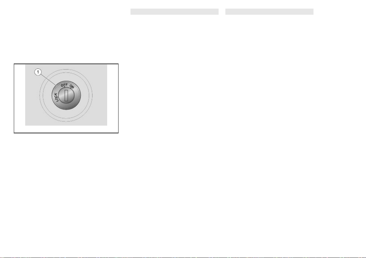
Key switch (01_10)
The ignition switch "1" is found on the
right side, near the headstock.
NOTE
THE KEY ACTIVATES THE IGNITION/
STEERING LOCK SWITCH, THE SADDLE LOCK AND THE GLOVE-BOX LID.
22
Sleutelschakelaar (01_10)
Ontstekingsschakelaar «1» vindt men op
de rechter kant, nabij de kop van de
stuurinrichting.
N.B.
DE SLEUTEL ACTIVEERT DE SCHA-
KELAAR VAN DE ONTSTEKING /
STUURSLOT, HET SLOT VAN HET ZADEL EN HET DEURTJE VAN DE OPBERGRUIMTE.
1 Vehicle / 1 Voertuing
NOTE
TWO KEYS ARE SUPPLIED WITH THE
VEHICLE (A SPARE ONE).
KEEP THE SPARE KEY IN A DIFFER-
ENT PLACE, NOT WITH THE VEHICLE.
N.B.
BIJ HET VOERTUIG WORDEN TWEE
SLEUTELS GELEVERD (ÉÉN RESERVESLEUTEL).
BEWAAR DE RESERVESLEUTEL
NIET OP HET VOERTUIG.
01_10
OFF: The engine and lights cannot be set
to work. The ignition key can be extracted.
ON: The engine and lights can be set to
work. The key cannot be extracted.
LOCK: The steering is locked. The engine and lights cannot be set to work. The
ignition key can be extracted.
Locking the steering wheel
To lock the steering:
•
Turn the handlebar fully to the
left.
•
Turn the ignition key to the
"LOCK"position.
OFF: De motor en de lichten kunnen niet
in werking worden gesteld. Het is mogelijk om de sleutel te verwijderen.
ON: De motor en de lichten kunnen in
werking worden gesteld. Het is niet mogelijk om de sleutel te verwijderen.
LOCK: Het stuur is geblokkeerd. De motor en de lichten kunnen niet in werking
worden gesteld. Het is mogelijk om de
sleutel te verwijderen.
Inschakeling van het stuurslot
Om de stuurinrichting te blokkeren:
•
Draai het stuur volledig naar
links.
•
Met de ontstekingssleutel draait
men de ontstekingsschakelaar
in positie «LOCK».
23
CAUTION
LET OP
01_11
AVOIDING LOSING CONTROL OF THE
VEHICLE, NEVER TURN THE KEY TO
"LOCK" WHILE RIDING.
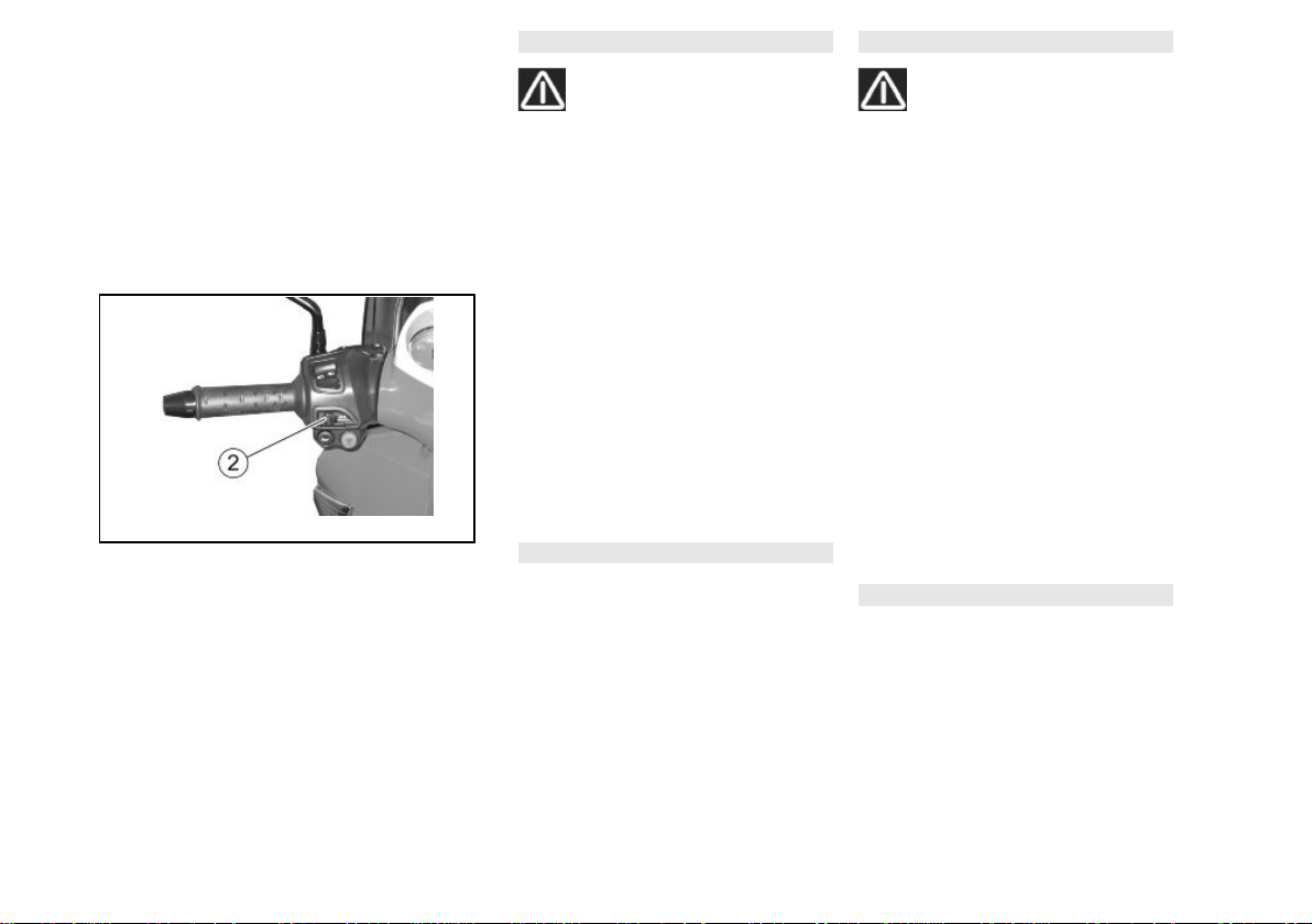
Switch direction indicators
(01_11)
Move the switch "2" to the left, to indicate
a left turn; move the switch "2" to the right,
to indicate a right turn.. Pressing the central part of the switch deactivates the turn
indicator. While the vehicle is in motion
the system automatically deactivates the
turn indicator system after 40 seconds or
500 m.
NOTE
ELECTRICAL COMPONENTS FUNC-
TION ONLY WHEN THE IGNITION KEY
IS SET TO "ON"
DRAAI DE SLEUTEL NOOIT IN POSITIE «LOCK» TIJDENS HET RIJDEN,
ZODAT MEN DE CONTROLE OVER
HET VOERTUIG NIET VERLIEST.
Schakelaar richtingaanwijzers
(01_11)
Verplaats schakelaar «2» naar links, om
aan te duiden dat men naar links draait;
Verplaats schakelaar «2» naar rechts,
om aan te duiden dat men naar rechts
draait; Plaats de schakelaar centraal om
de richtingaanwijzer te deactiveren. Met
het voertuig in beweging, grijpt het automatisch terugkeersysteem in, dat de richtingaanwijzer deactiveert na 40 seconden of na 500 m.
N.B.
DE ELEKTRISCHE ONDERDELEN
WERKEN ENKEL WANNEER DE ONTSTEKINGSSCHAKELAAR ZICH IN POSITIE «ON» BEVINDT
24
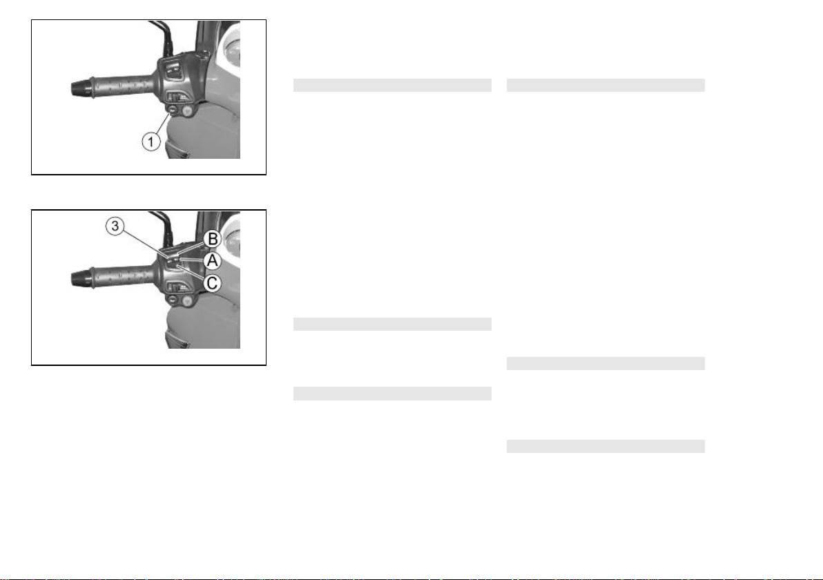
Horn button (01_12)
1 Vehicle / 1 Voertuing
Drukknop claxon (01_12)
01_12
01_13
Pressing the button "1" activates the
horn.
NOTE
ELECTRICAL COMPONENTS FUNC-
TION ONLY WHEN THE IGNITION KEY
IS SET TO "ON"
Light switch (01_13)
If the light switch "3" is set to "B", this activates the high-beam light; if it is set to
"A", this activates the low-beam light.
Turning the light switch to "C" the highbeam light flashes.
NOTE
ELECTRICAL COMPONENTS FUNC-
TION ONLY WHEN THE IGNITION KEY
IS SET TO "ON"
NOTE
ONCE THE LIGHT SWITCH IS RE-
LEASED FROM THE PASSING MODE
IN "C"THE HIGH-BEAM LIGHT STOPS
FLASHING.
Door op drukknop «1» te drukken, activeert men de akoestische melder.
N.B.
DE ELEKTRISCHE ONDERDELEN
WERKEN ENKEL WANNEER DE ONTSTEKINGSSCHAKELAAR ZICH IN POSITIE «ON» BEVINDT
Koplampschakelaar (01_13)
Wanneer de omleider van de lichten «3»
zich in positie «B» bevindt, wordt het
groot licht geactiveerd; wanneer hij zich
in positie «A» bevindt, wordt het dimlicht
geactiveerd.
Door op de omleider van de lichten te
drukken in positie «C», activeert men het
knipperen van het groot licht.
N.B.
DE ELEKTRISCHE ONDERDELEN
WERKEN ENKEL WANNEER DE ONTSTEKINGSSCHAKELAAR ZICH IN POSITIE «ON» BEVINDT
N.B.
WANNEER MEN DE OMLEIDER VAN
DE LICHTEN IN MODALITEIT KNIPPEREN «C» LOSLAAT, WORDT HET
25
KNIPPEREN VAN HET GROOT LICHT
GEDEACTIVEERD.
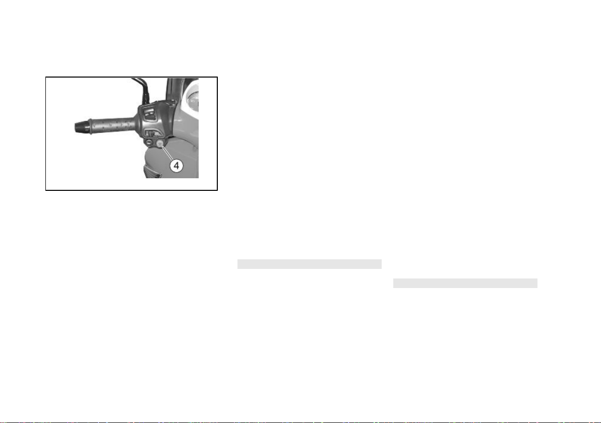
01_14
Emergency flashing light
button (01_14)
Using the HAZARD switch "4" it is possible to activate/deactivate the hazard
lights.
ACTIVATION
With the ignition switch in "ON".
Press to activate the four arrows. Now it
is possible to turn the ignition switch to
"OFF" and withdraw the key.
DEACTIVATION
Insert the key in the ignition switch and
turn it to "ON", press the HAZARD switch
again to deactivate the system.
NOTE
ACTIVATE AND DEACTIVATE THE
HAZARD LIGHTS ONLY WHEN THE
IGNITION KEY IS SET TO "ON"
Inschakelknop alarmlichten
(01_14)
Met drukknop HAZARD «4» is het mogelijk om de knipperlichten aan/uit te
schakelen.
INSCHAKELING
Met de ontstekingsschakelaar in «ON».
Druk om de vier richtingaanwijzers in te
schakelen. Nu is het mogelijk om de ontstekingsschakelaar in positie «OFF» te
draaien, en om de sleutel te verwijderen.
UITSCHAKELING
Plaats de sleutel in de ontstekingsschakelaar, en draai ze in positie «ON», druk
opnieuw op de drukknop HAZARD om
het systeem te deactiveren.
N.B.
HET IN- EN UITSCHAKELEN VAN DE
KNIPPERLICHTEN KAN ENKEL UITGEVOERD WORDEN MET DE ONTSTEKINGSSCHAKELAAR IN POSITIE
«ON».
26

Start-up button (01_15)
1 Vehicle / 1 Voertuing
Startknop (01_15)
01_15
01_16
By pressing the starter button «2», the
starter motor makes the engine rotate.
NOTE
ELECTRICAL COMPONENTS FUNC-
TION ONLY WHEN THE IGNITION KEY
IS SET TO "ON"
Engine stop button (01_16)
It acts as an engine cut-off or emergency
stop switch. With the switch «1» in «B»
RUN, it is possible to start the engine;
pressing the switch when set to «A»
OFF will stop the engine.
NOTE
ELECTRICAL COMPONENTS FUNC-
TION ONLY WHEN THE IGNITION KEY
IS SET TO "ON"
CAUTION
DO NOT ACTIVATE THE ENGINE
STOP SWITCH WHILE RIDING THE
VEHICLE.
Door op drukknop «2» te drukken, doet
het startmotortje de motor draaien.
N.B.
DE ELEKTRISCHE ONDERDELEN
WERKEN ENKEL WANNEER DE ONTSTEKINGSSCHAKELAAR ZICH IN POSITIE «ON» BEVINDT
Stopschakelaar motor (01_16)
Dit is een veiligheidsschakelaar of een
noodstopschakelaar. Met schakelaar
«1» ingedrukt in positie «B» RUN, is het
mogelijk om de motor te starten; door er
op te drukken in positie «A» OFF, wordt
de motor stilgelegd.
N.B.
DE ELEKTRISCHE ONDERDELEN
WERKEN ENKEL WANNEER DE ONTSTEKINGSSCHAKELAAR ZICH IN POSITIE «ON» BEVINDT
LET OP
RAAK DE STOPSCHAKELAAR VAN
DE MOTOR NIET AAN TIJDENS HET
RIJDEN.
27
CAUTION
LET OP
01_17
WITH THE ENGINE OFF AND THE IGNITION SWITCH SET TO «ON» THE
BATTERY MAY GET DISCHARGED.
WITH THE ENGINE OFF AND AFTER IT
STOPS TURN THE IGNITION SWITCH
TO «OFF».
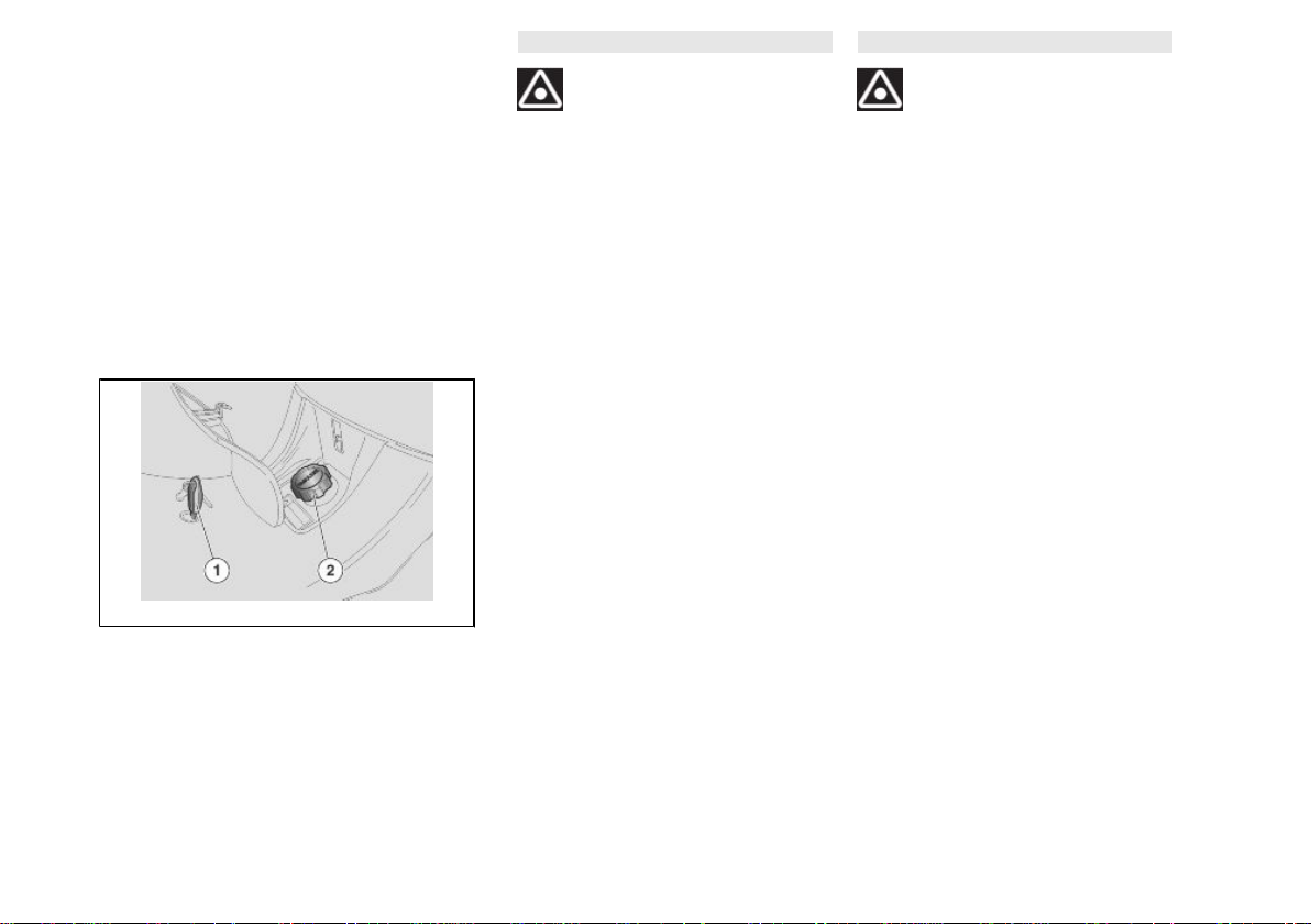
Fuel tank (01_17)
To reach the fuel tank cap:
•
Insert the key "1" into the fuel
tank compartment lock.
•
Turn the key "1" anticlockwise.
•
Unscrew the tank cap "2".
MET DE MOTOR STIL EN DE ONTSTEKINGSSCHAKELAAR MET SLEUTEL
IN POSITIE «ON», KAN DE ACCU ONTLADEN. WANNEER HET VOERTUIG
STILSTAAT NADAT MEN DE MOTOR
HEEFT STILGELEGD, DRAAIT MEN
DE ONTSTEKINGSSCHAKELAAR IN
POSITIE «OFF».
Benzinetank (01_17)
Om de dop van de brandstoftank te bereiken:
•
Plaats sleutel «1» in het slot van
de ruimte van de brandstoftank.
•
Draai sleutel «1» in tegenwijzerszin.
•
Draai de dop van de tank «2»
los.
28
Power supply socket (01_18)
1 Vehicle / 1 Voertuing
Stopcontact (01_18)
01_18
01_19
•
There is a 12V socket inside of
the glovebox "3" and a lever "4"
to open the saddle manually..
•
The 12V socket can be used to
power equipment with a maximum power of 180 W (mobile
telephones, hand lamp, etc.).
CAUTION
USING THIS SOCKET FOR A LONG
PERIOD CAN RESULT IN A FULLY
DISCHARGED BATTERY.
The saddle (01_19)
To unlock the saddle:
•
open the glovebox.
•
Pull the lever «4» to unlock the
saddle.
To lock the saddle:
•
lower and press it (without forcing it) to trip the lock.
•
Binnenin de documentenruimte
is er een stopcontact van 12V
«3» en een hendel «4» voor de
manuele opening van het zadel
voorzien.
•
Het stopcontact van 12 V kan
gebruikt worden voor het voeden van gebruiksvoorwerpen
van maximum 180 W (GSM, inspectielamp, enz.).
LET OP
EEN LANG GEBRUIK VAN HET STOP-
CONTACT WANEER DE MOTOR UITSTAAT, KAN DE ACCU VOLLEDIG
DOEN ONTLADEN.
Het zadel (01_19)
Om het zadel te deblokkeren:
•
open de documentenruimte.
•
Trek aan de hendel «4» om het
zadel los te koppelen.
Om het zadel te blokkeren:
•
plaats het omlaag en druk erop
(zonder te forceren), zodat het
slot klikt.
29
CAUTION
LET OP
01_20
BEFORE RIDING, MAKE SURE THAT
THE SADDLE IS CORRECTLY
LOCKED INTO POSITION.
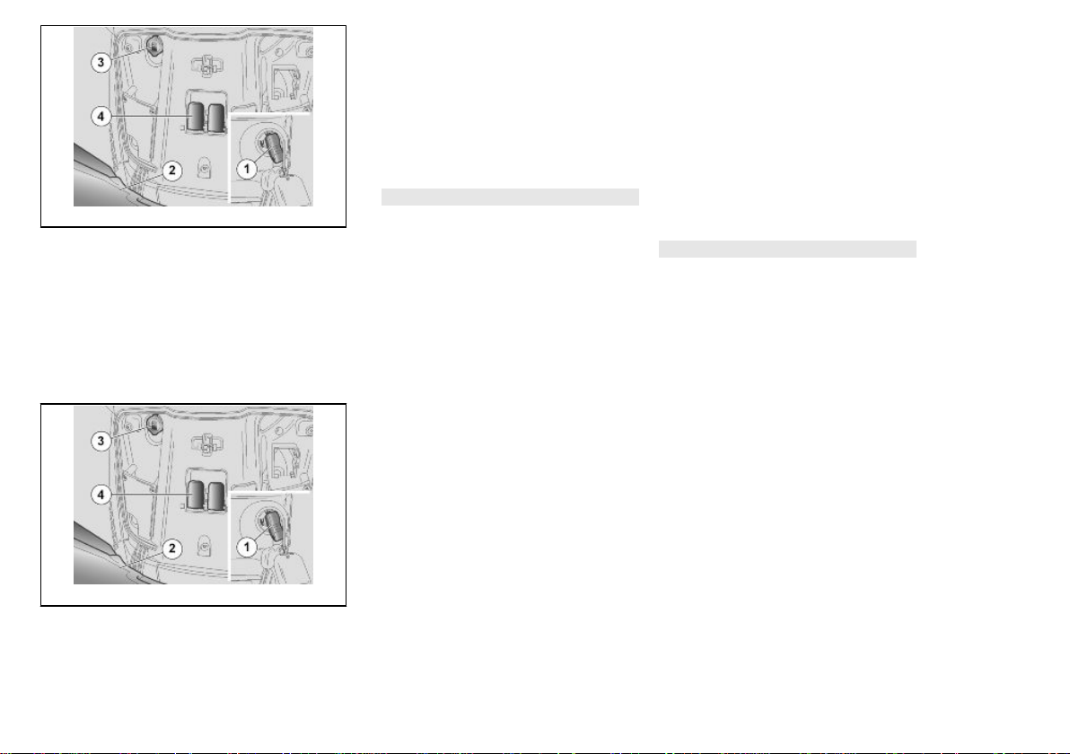
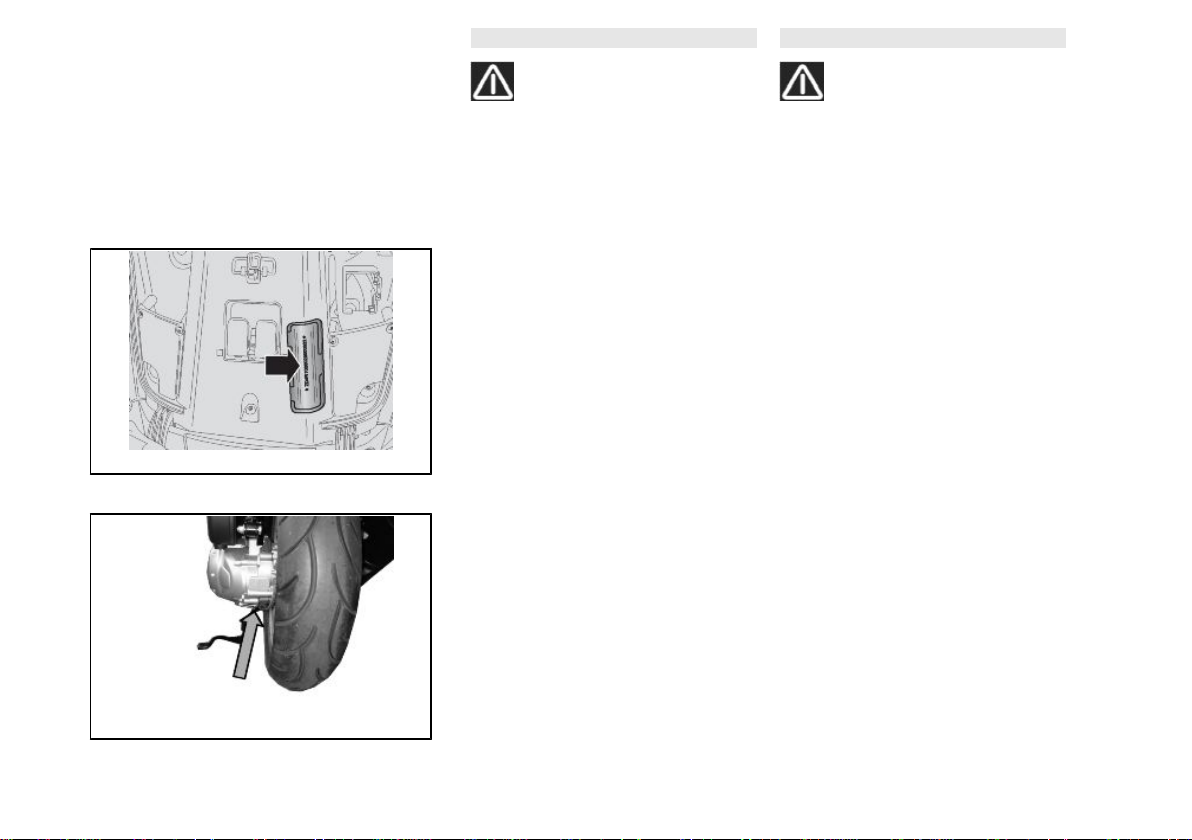
Identification (01_20, 01_21)
Chassis number
The chassis number is stamped on the
central chassis bar. To read the chassis
number it will be necessary to open the
glove-box and remove the snap-on protection.
Chassis
No.: ...............................................
Engine number
The engine number is stamped near the
rear shock absorber lower support.
Engine
No.: ...............................................
VOORALEER MEN GAAT RIJDEN,
CONTROLEERT MEN OF HET ZADEL
CORRECT GEBLOKKEERD IS.
Identificatie (01_20, 01_21)
Framenummer
Het framenummer is gedrukt op de centrale buis van het frame. Voor het lezen
ervan moet men de opbergruimte openen en de erop gemonteerde klemverbindingbescherming verwijderen.
Framenum-
mer: ................................................
Motornummer
Het motornummer is gedrukt in de nabijheid van de onderste steun van de achterste schokdemper.
Motornum-
mer: ................................................
01_21
30
 Loading...