

Page 1

TELAIO
CHASSIS
CHASIS
7
Page 2

CHASSIS
CHASIS
CONTENTS
BODY .................................................... 7-1
FAIRING DISASSEMBLY ..................... 7-4
DRIVER'S SEAT DISASSEMBLY ......... 7-6
REAR FAIRING COVER ASSEMBLY..... 7-6
FUEL TANK DISASSEMBLY................. 7-6
REAR FAIRING DISASSEMBLY ........... 7-8
REAR CENTRAL COWLING
DISASSEMBLY...................................... 7-8
FRONT WHEEL .................................. 7-10
DISASSEMBLY ................................... 7-12
BEARING REPLACEMENT.................. 7-12
INSPECTION - REASSEMBLY ............ 7-14
REAR WHEEL ..................................... 7-18
DISASSEMBLY ................................... 7-20
BEARING REPLACEMENT.................. 7-20
INSPECTION - REASSEMBLY ............ 7-20
TYRES..................................................7-22
TYRE REMOVAL ................................. 7-22
INSPECTION ....................................... 7-26
VALVE INSTALLATION ...................... 7-28
TYRE MOUNTING .............................. 7-28
FRONT BRAKE ................................... 7-32
BRAKE PADS REPLACEMENT ........... 7-34
BRAKE DISC INSPECTION.................. 7-34
AIR BLEEDING FROM THE
HYDRAULIC CIRCUIT.......................... 7-34
REAR BRAKE ..................................... 7-36
BRAKE PADS REPLACEMENT...........
BRAKE DISC CONTROL.......................
AIR BLEEDING FROM THE
HYDRAULIC CIRCUIT..........................
BRAKE CONTROL PEDAL
BALL JOINT ........................................
STEERING .......................................... 7-40
DISASSEMBLY ................................... 7-42
INSPECTION ....................................... 7-44
REASSEMBLY - ADJUSTMENT......... 7-44
FRONT FORK ..................................... 7-46
LEG GUARDS REMOVAL ................... 7-48
RIGHT LEG GUARD DISASSEMBLY
(HYDRAULIC BRAKE) ......................... 7-50
LEFT LEG GUARD DISASSEMBLY
(SPRING) ............................................. 7-54
FORK OIL ............................................ 7-56
COMPONENTS INSPECTION ............ 7-56
LEG GUARDS REINSTALLATION...... 7-60
REAR SUSPENSION .......................... 7-62
REMOVAL AND DISASSEMBLY........ 7-64
INSPECTION ....................................... 7-66
REASSEMBLY AND
REINSTALLATION .............................. 7-68
FRONT FORK AND REAR SHOCK
ABSORBER ADJUSTMENT............... 7-70
7-38
7-38
7-38
7-38
INDICE
CARROCERIA .......................................7-1
DESMONTAJE DEL CARENADO ......... 7-4
DESMONTAJE DEL SILLIN
DEL PILOTO ..........................................7-6
MONTAJE DE LA CUBIERTA
DEL CARENADO TRASERO ................. 7-6
DESMONTAJE DEL DEPOSITO
DEL COMBUSTIBLE ............................. 7-6
DESMONTAJE DEL CARENADO
TRASERO .............................................. 7-8
DESMONTAJE DEL CARENADO
CENTRAL TRASERO ............................ 7-8
RUEDA DELANTERA.......................... 7-10
DESMONTAJE ................................... 7-12
SUBSTITUCION DE LOS COJINETES . 7-12
CONTROL - REMONTAJE................... 7-14
RUEDA TRASERA .............................. 7-18
DESMONTAJE ................................... 7-20
SUBSTITUCION DE LOS COJINETES . 7-20
CONTROL - REMONTAJE................... 7-20
NEUMATICOS ................................... 7-22
DESMONTAJE ................................... 7-22
CONTROL ........................................... 7-26
MONTAJE DE LA VALVULA .............. 7-28
MONTAJE DEL NEUMATICO ............ 7-28
FRENO DELANTERO.......................... 7-32
SUBSTITUCION DE LAS PASTILLAS
DEL FRENO ......................................... 7-34
CONTROL DEL DISCO DEL FRENO.... 7-34
PURGACION DEL AIRE DEL
CIRCUITO HIDRAULICO ..................... 7-34
FRENO TRASERO .............................. 7-36
SUBSTITUCION DE LAS PASTILLAS
DEL FRENO ......................................... 7-38
CONTROL DEL DISCO DEL FRENO.... 7-38
PURGACION DEL AIRE DEL
CIRCUITO HIDRAULICO ..................... 7-38
ARTICULACION DEL PEDAL
DE MANDO DEL FRENO..................... 7-38
DIRECCION ........................................ 7-40
DESMONTAJE ................................... 7-42
CONTROL ........................................... 7-44
REMONTAJE - REGULACION ........... 7-44
HORQUILLA ....................................... 7-46
EXTRACCION DE LOS BRAZOS
DE LA HORQUILLA ............................. 7-48
DESMONTAJE DEL BRAZO
DERECHO DE LA HORQUILLA
(FRENO HIDRAULICO)........................ 7-50
DESMONTAJE DEL BRAZO IZQUIER-
DO DE LA HORQUILLA (MUELLE) ..... 7-54
ACEITE DE LA HORQUILLA ............... 7-56
CONTROL DE LOS COMPONENTES . 7-56
INSTALACION DE LOS BRAZOS
DE LA HORQUILLA ............................. 7-60
SUSPENSION TRASERA .................. 7-62
EXTRACCION Y DESMONTAJE......... 7-64
CONTROL ........................................... 7-66
REMONTAJE E INSTALACION.......... 7-68
REGULACION DE LA HORQUILLA Y
DEL AMORTIGUADOR TRASERO..... 7-70
7
Page 3

7 - 1MTELAIO
CARROZZERIA -
1
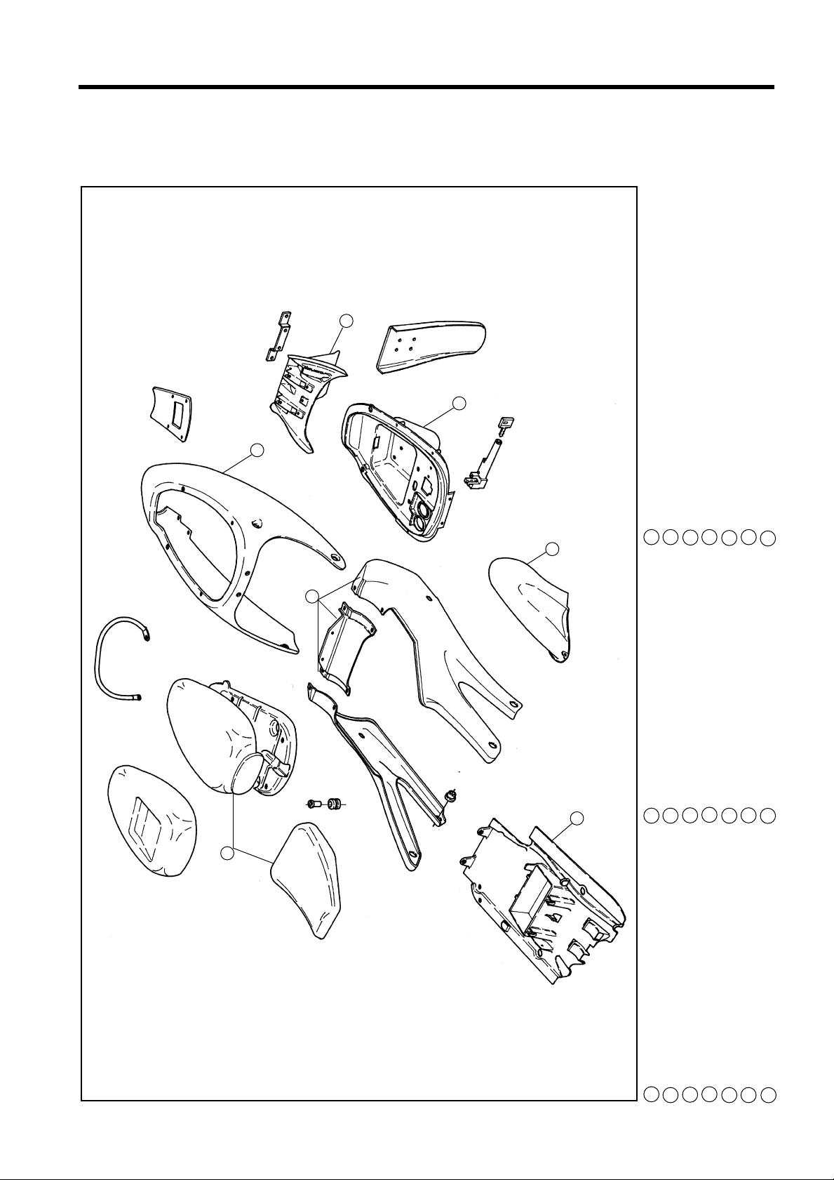
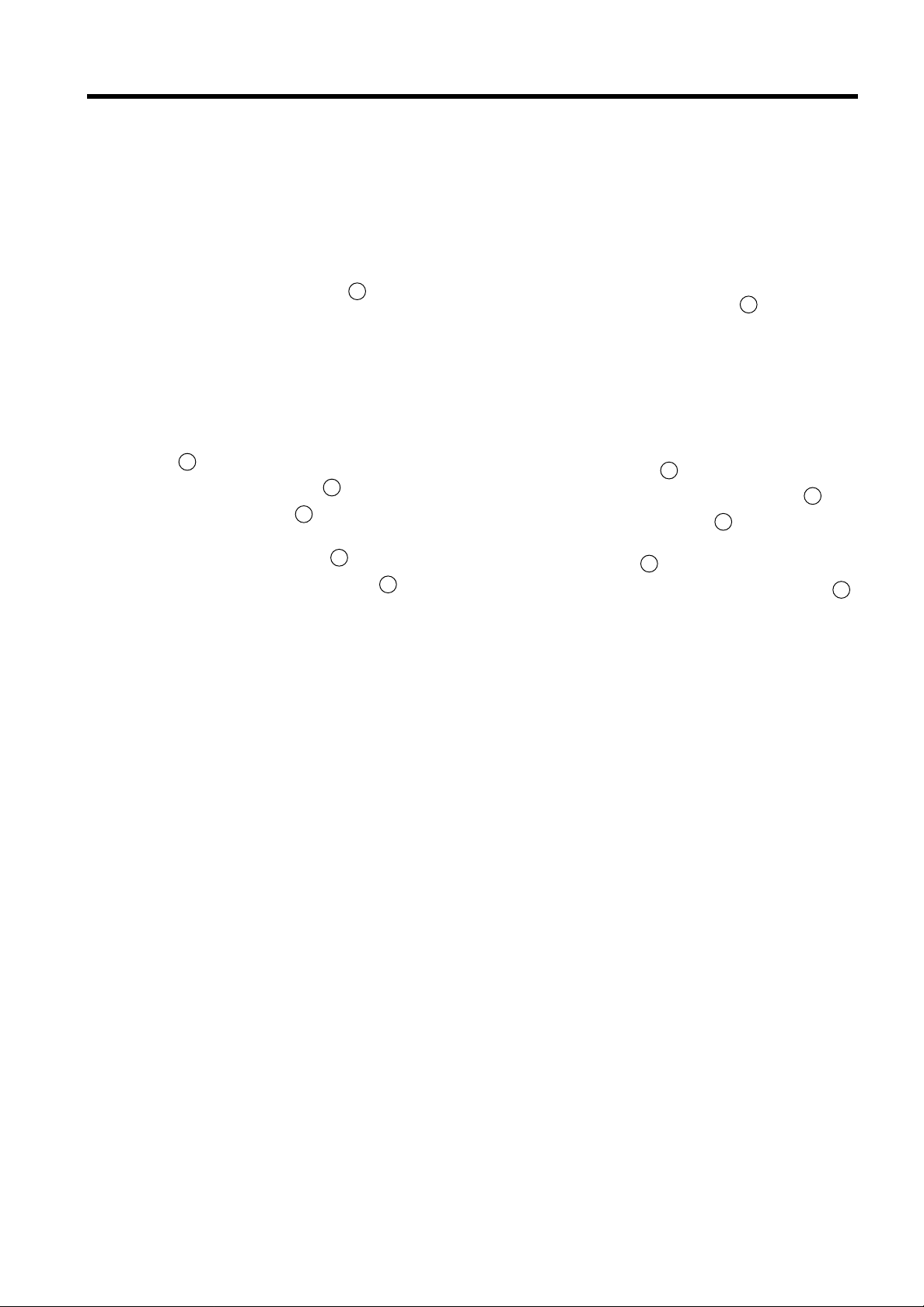
BODY
- CARROCERIA
010 Parabrisas
020 Carenado superior
030 Semicarenados laterales
040 Carenado inferior central
050 Flancos interiores
060 Guardabarro delantero
3
2
4
3
010 Windshield
020 Front fairing
030 Side half-fairings
040 Lower central fairing
050 Internal panels
5
060 Front mudguard
6
010 Parabrezza
020 Cupolino
030 Semicarene laterali
040 Carena inferiore centrale
050 Fianchetti interni
060 Parafango anteriore
Page 4
CHASSIS
7 - 2CHASIS
2
3
1
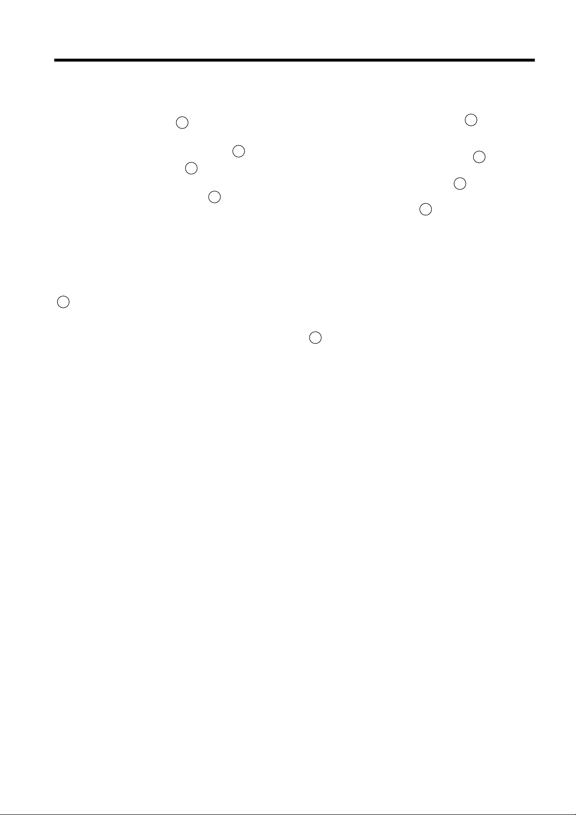
010 Carenado trasero
020 Porta-matrícula
030 Equipaje trasero
040 Guardabarro trasero
050 Carenado central trasero
060 Sillín del piloto y del pasajero
4
5
7
6
010 Rear fairing
020 Number plate holder
030 Rear oddments tray
040 Rear mudguard
070 Soporte de la batería/guardabarro
050 Rear central cowling
060 Driver's and passenger's seat
070 Battery/mudguard holder
010 Codone
020 Portatarga
030 Vasca portaoggetti posteriore
040 Parafango posteriore
050 Carena centrale posteriore
060 Sella pilota e passeggero
070 Supporto batteria/parafango
Page 5
CHASSIS
7 - 4CHASIS
FAIRING DISASSEMBLY
LEFT SIDE HALF-FAIRING
●
Remove the inside clip 010.
●
Remove the screw 020 fastening half-fairing to
front fairing.
●
Remove the three screws 030.
●
Remove the three screws 040 fastening halffairing to the lower fairing.
●
Remove half-fairing.
●
Unscrew tachometer cable fastening ring nut
050, remove from housing and from the two
fairleads inside the half-fairing.
NOTE:
If the right half-fairing has already been removed,
it is unnecessary to remove the three screws 040.
RIGHT SIDE HALF-FAIRING
DESMONT AJE DEL CARENADO
SEMICARENADO LA TERAL IZQUIERDO
●
Sacar el muelle interior 010.
●
Sacar el tornillo 020 que fija el semicarenado al
carenado superior.
●
Sacar los tres tornillos 030.
●
Sacar los tres tornillos 040 que fijan el semicarenado al carenado inferior.
●
Sacar el semicarenado.
●
Desatornillar la tuerca 050 de fijación del cable
del taquímetro, sacarlo de su alojamiento y de
los dos pasacabos en el interior del semicarenado.
NOTA:
Si ya se ha sacado el semicarenado derecho, no
hay que sacar los tres tornillos 040.
SEMICARENADO LA TERAL DERECHO
●
Remove the inside clip 010.
●
Remove the screw 020 fastening half-fairing to
front fairing.
●
Remove the three screws 030.
●
Remove the three screws 040 fastening the
half-fairing to the lower fairing.
●
Remove half-fairing.
NOTE:
If the left half-fairing has already been removed, it
is unnecessary to remove the three screws 040.
FRONT FAIRING
●
Remove the four screws 010.
●
Remove the central screw 020.
●
Disconnect the indicator connectors.
●
Disconnect the headlight connector from the
connector plate on the front chassis.
NOTE:
To disassemble the front fairing without removing
the side half-fairings, remove the two front screws
which fix the front fairing to the half-fairings.
●
Sacar el muelle interior 010.
●
Sacar el tornillo 020 que fija el semicarenado al
carenado superior.
●
Sacar los tre tornillos 030.
●
Sacar los tres tornillos 040 que fijan el semicarenado al carenado inferior.
●
Sacar el semicarenado.
NOTA:
Si ya se ha sacado el semicarenado izquierdo, no
hay que sacar los tres tornillos 040.
CARENADO SUPERIOR
●
Sacar los cuatro tornillos 010.
●
Sacar el tornillo central 020.
●
Sacar los conectores de los indicadores de dirección.
●
Desconectar el conector de los faros de la placa
portaconectores en el chasis delantero.
NOTA:
Si se quiere desmontar el carenado superior sin sacar los semicarenados laterales, hay que sacar también los dos tornillos delanteros que fijan el carenado superior a los semicarenados.
REASSEMBL Y
Perform disassembly operations in reverse order.
REMONTAJE
Realizar en sentido contrario las operaciones de
desmontaje.
Page 6

CHASSIS
7 - 6CHASIS
DRIVER'S SEA T DISASSEMBL Y
●
Raise the front of the seat upholstery 010.
●
Remove screw 020 and remove the seat from
the front.
REASSEMBL Y
●
Fit the rear flaps into their housings.
●
Lower the front of the seat.
●
Tighten screw 020 securely.
REAR FAIRING COVER ASSEMBLY
To replace the passenger's seat upholstery with
the rigid fairing cover, proceed as follows:
●
Disassemble the passenger's seat 010.
●
Remove the four nuts 020which fasten the seat
upholstery.
●
Assemble the rigid fairing cover to the base of
the seat and fix with the self-tapping screws
supplied with the cover.
FUEL TANK DISASSEMBLY
DESMONTAJE DEL SILLIN DEL PILOTO
●
Levantar la parte delantera del revestimiento
del sillín 010.
●
Sacar el tornillo 020y extraer el sillín por la parte delantera.
REMONT AJE
●
Introducir las aletas traseras en sus alojamientos.
●
Bajar la parte delantera del sillín.
●
Enroscar a tope el tornillo 020.
MONTAJE DE LA CUBIER T A DEL CARENADO
TRASERO
Para substituir el revestimiento del sillín del pasajero con la cubierta rígida del carenado trasero,
hay que seguir el siguiente procedimiento:
●
Desmontar el sillín del pasajero 010.
●
Sacar las cuatro tuercas 020 que fijan el revestimiento del sillín.
●
Montar la cubierta rígida del carenado trasero
en la base del sillín y fijarla con los seis tornillos autofileteados que van con la cubierta.
WARNING:
Before disassembling the tank, check that the fuel
cock is closed and the engine cold. Check also that
there are no lit cigarettes, free flames or incandescent bodies in the vicinity: DANGER OF FIRE!
●
Turn the fuel cock to "OFF".
●
Disassemble the driver's seat.
●
Carefully raise the rear part of the tank and push back to release the front check tab.
●
Slightly incline the tank on its left side.
●
Remove the fuel hose 010 and water drain hose 020fastened with an elastic clamp.
REASSEMBL Y
Perform the disassembly operations in reverse order.
DESMONTAJE DEL DEPOSITO DEL
COMBUSTIBLE
ATENCION:
Antes de desmontar el depósito, hay que asegurarse de que el grifo del combustible esté cerrado
y que el motor esté frío. Cercionarse de que no
hayan cigarrillos encendidos, llamas libres o cuerpos incandescentes, cerca de la motocicleta: PELIGRO DE INCENDIO !
●
Girar el grifo del combustible en la posición
"OFF".
●
Desmontar el sillín del piloto.
●
Levantar con cuidado la parte superior del
depósito y empujarlo hacia atrás para soltar la
aleta delantera de retén.
●
Inclinar un poquito el depósito hacia el flanco
izquierdo.
●
Sacar el tubo del combustible 010 y el tubo de
vaciado del agua 020 fijado con una abrazadera elástica.
REMONT AJE
Realizar en sentido inverso las operaciones del desmontaje.
Page 7
CHASSIS
7 - 8CHASIS
REAR FAIRING DISASSEMBLY
●
Disassemble the passenger's seat.
●
Remove the four screws 010.
●
Remove the two screws 020.
●
Remove the two screws 030.
●
Remove the rear fairing from the rear of the
motorcycle, carefully widening the bottom part
to release it from the passenger seat lock.
●
Disconnect tail light connector 040.
REASSEMBL Y
Perform the disassembly operations in reverse order, being careful not to widen the lower part of
the rear fairing excessively.
REAR CENTRAL COWLING DISASSEMBL Y
●
Disassemble the driver's seat.
●
Disassemble the passenger's seat.
●
Disassemble the rear fairing.
●
Disassemble the four screws 010 and bushes
which fasten the rear part of the chassis.
●
Remove the rear central cowling from above.
REASSEMBL Y
Perform the disassembly operations in reverse order, being careful to centre the bushes correctly
over the four fastening screws.
Fully tighten the screws which fasten the rear part
of the chassis.
DESMONTAJE DEL CARENADO TRASERO
●
Desmontar el sillín del pasajero.
●
Sacar los cuatro tornillos 010.
●
Sacar los dos tornillos 020.
●
Sacar los dos tornillos 030.
●
Extraer el carenado trasero de la parte trasera
de la motocicleta, ensanchando con cuidado la
parte inferior para soltarlo de la cerradura del
sillín del pasajero.
●
Desconectar el conector 040 del faro trasero.
REMONT AJE
Realizar en sentido contrario las operaciones del
desmontaje, teniendo cuidado en no ensanchar
excesivamente la parte inferior del carenado trasero.
DESMONTAJE DEL CARENADO CENTRAL
TRASERO
●
Desmontar el sillín del piloto.
●
Desmontar el sillín del pasajero.
●
Desmontar el carenado trasero.
●
Desmontar los cuatro tornillos 010 y sus casquillos correspondientes que fijan también la
parte trasera del chasis.
●
Extraer por arriba el carenado central trasero.
REMONT AJE
Realizar en sentido contrario las operaciones de
desmontaje, teniendo cuidado en centrar correctamente los casquillos en los cuatro tornillos de fijación.
Apretar a tope los tornillos que fijan también la
parte trasera del chasis.
Page 8
CHASSIS
7 - 10CHASIS
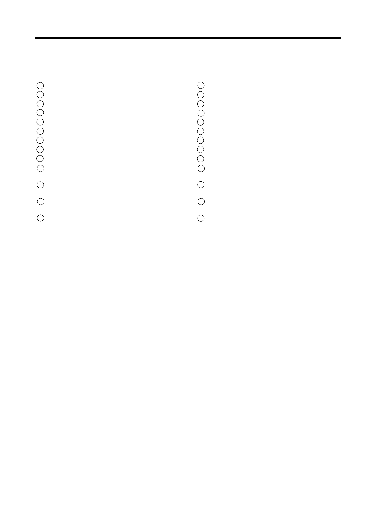
FRONT WHEEL
010 Wheel pin
020 Tachometer socket
030 Brake disc
040 Wheel rim
050 Bearings spacer
060 Bearings
070 External spacer
080 Wheel pin screw
0A0= Apply LOCTITEmedium thread lock:
15 - 25 Nm (1,5 - 2,5 kgm)
0B0 = Apply lithium grease
0C0 = Wheel pin screw:
80 Nm (8,0 kgm)
RUEDA DELANTERA
010 Perno de la rueda
020 Toma para taquímetro
030 Disco del freno
040 Llanta de la rueda
050 Separador para cojinetes
060 Cojinetes
070 Separador exterior
080 Tornillo del perno de la rueda
0A0= Aplicar LOCTITEfrena roscas medio:
15 - 25 Nm (1,5 - 2,5 kgm)
0B0 = Aplicar grasa a base de litio
0C0 = Tornillo del perno de la rueda:
80 Nm (8,0 kgm)
Page 9
CHASSIS
7 - 12CHASIS
DISASSEMBL Y
WARNING:
Before disassembling the wheel, set the motorcycle securely on the special stand whose support
pins should be fitted into the holes on the chassis.
●
Remove the fastening screws 010 and disassemble both the front brake calipers.
CAUTION:
When the calipers are disassembled do not pull
the brake lever as the caliper pistons might leave
their housings, and this might cause the brake
fluid to leak.
●
Detach the tachometer cable, unscrewing the
ring nut 020.
●
Loosen the wheel pin screw 050.
●
Loosen the four screws 030 at the basis of the
fork tubes.
●
Remove the wheel pin screw 050.
●
Unscrew and remove the wheel pin 040.
●
Remove the wheel.
DESMONTAJE
ATENCION:
Antes de realizar el desmontaje de la rueda, hay
que apoyar correctamente la motocicleta con el
caballete especial, introduciendo los pernos de
sujeción del mismo en los foros del chasis.
●
Sacar los tornillos de fijación 010 y desmontar
las dos pinzas de los frenos delanteros.
ADVERTENCIA:
Cuando las pinzas del freno están desmontadas
no hay que tirar la palanca del freno, pues los pistones de la pinza podrían salir de su alojamiento
causando la salida del líquido de los frenos.
●
Desempalmar el cable del taquímetro, desenroscando la tuerca 020.
●
Aflojar el tornillo del perno de la rueda 050.
●
Aflojar los cuatro tornillos 030 en la base de las
barras de la horquilla.
●
Sacar el tornillo 050 del perno de la rueda.
●
Desatornillar y extraer el perno de la rueda 040.
●
Sacar la rueda.
BEARING REPLACEMENT
NOTE:
After every disassembly operation, the bearings
must be replaced.
●
Clean the wheel hub.
●
Remove the bearing by hitting the internal ring
of the bearing itself with a copper or aluminium punch.
●
Remove the spacer and proceed as before to
remove the other bearing.
●
Clean the wheel hub thoroughly.
NOTE:
Begin assembling the new bearings starting from
the one on the right (opposite the tachometer
socket), setting it against the hub housing.
●
With a pad of the same diameter as the external ring, push the new bearing firmly into its
housing.
●
Fit the spacer into the hub body.
●
Using the pad, push the other bearing into its
housing.
SUBSTITUCION DE LOS COJINETES
NOTA:
Después de cada desmontaje, los cojinetes deben
ser substituídos.
●
Limpiar el cubo de la rueda.
●
Extraer el cojinete golpeando el anillo interior
del mismo cojinete con un punzón de cobre o
de aluminio.
●
Extraer el separador y operar del mismo modo
como para la extracción del otro cojinete.
●
Limpiar perfectamente el cubo de la rueda.
NOTA:
Comenzar el montaje de los nuevos rodamientos
desde el derecho (lado opuesto a la toma del velocímetro), hasta que se apoye en el alojamiento
del buje.
●
Con un tampón de diámetro igual al del anillo
exterior, empujar el nuevo cojinete a tope en
su alojamiento.
●
Introducir el separador en el cuerpo del cubo.
●
Empleando el tampón, empujar en su alojamiento el otro cojinete.
CAUTION:
Do not hammer the bearing balls or inner ring.
ADVERTENCIA:
No golpear las esferas o el anillo del cojinete. El
apoyo del golpe debe ser sobre el anillo exterior.
Page 10

CHASSIS
7 - 14CHASIS
INSPECTION
BEARINGS
After assembling the wheel hub bearings, check
the inner ring clearance by hand.
Turn the inner ring by hand to check that it rotates
smoothly and silently.
Replace any faulty bearings.
WHEEL PIN
Using a dial gauge, check the runout limit of the
wheel pin. If the runout limit exceeds the maximum value, replace the pin.
Maximum runout limit: 0,25 mm
RIM
Check that the axial and radial runout of the rim
does not exceed the maximum value. Excess runout is usually caused by consumed or worn or
loose wheel bearings and decreases when the bearings are replaced. If after replacing the bearings
the runout does not return to the value indicated,
replace the rim.
Maximum runout limit (radial and axial): 2,0 mm
CONTROL
COJINETES
Después de haber montado los cojinetes en el cubo de la rueda, hay que controlar manualmente el
juego del anillo interior.
Girar con la mano el anillo interior, para verificar
que ruede de manera suave y sin ruido.
Substituir los cojinetes anomarles.
PERNO DE LA RUEDA
Usando un comparador, controlar la excentricidad
del perno de la rueda. Si la excentricidad supera el
valor límite, substituir el perno.
Excentricidad máxima: 0,25 mm
LLANT A
Verificar que la excentricidad axial o radial de la
llanta no supere el valor límite. Una excentricidad
excesiva normalmente está causada por los cojinetes de la rueda desgastados o aflojados y disminuye substituyendo los cojinetes. Si después de
haber substituído los cojinetes la excentricidad no
vuelve al límite indicado, hay que substituir la llanta.
Excentricidad máxima (axial y radial): 2,0 mm
REASSEMBL Y
Reassemble the front wheel by performing the disassembly operations in reverse order and paying
attention to the following points:
BEARINGS
●
Apply lithium grease before reassembling the
bearings.
TACHOMETER SOCKET
●
Before reassembling the tachometer socket,
rub it with lithium grease.
●
When the socket is installed on the hub, check
that the socket tab fits the hub housing properly.
●
Before tightening the wheel pin, place the tachometer socket into position properly, with
the cable housing in contact with the ledge on
the front fork leg guard.
REMONTAJE
Volver a montar la rueda delantera siguiendo en
sentido contrario las mismas operaciones de desmontaje y teniendo cuidado con los puntos siguientes:
COJINETES
●
Aplicar grasa a base de litio antes de volver a
montar los cojinetes.
TOMA DEL T AQUIMETRO
●
Antes de volver a montar la toma del taquímetro, hay que engrasarla con grasa a base de litio.
●
Cuando se instala la toma en el cubo, hay que
verificar que la lengüeta de la toma se introduzca correctamente en el alojamiento que
hay en el cubo.
●
Antes de apretar el perno de la rueda, hay que
colocar correctamente la toma del taquímetro,
con el alojamiento del cable en contacto con el
tope que hay en los brazos de la horquilla.
Page 11
CHASSIS
7 - 16CHASIS
WHEEL PIN
●
Grease the wheel pin 040 with lithium grease
and fit it into the wheel hub.
●
Fit and tighten the wheel pin screw 050.
●
Tighten the four screws 030 at the base of the
fork tubes.
●
Tighten the wheel pin screw 050 to the required torque.
Tightening torques
Wheel pin screw: 80 Nm (8,0 kgm)
Wheel pin locking screws: 10 Nm (1,0 kgm)
BRAKE CALIPERS
Assemble the brake calipers, tightening the screws
010 to the required torque.
Brake caliper screw tightening torque:
45 - 55 Nm (4,5 - 5,5 kgm)
PERNO DE LA RUEDA
●
Engrasar el perno de la rueda 040 con grasa a
base de litio e introducirlo en el cubo de la rueda.
●
Introducir y enroscar el tornillo 050 del perno
de la rueda.
●
Apretar los cuatro tornillos 030 en la base de
las barras de la horquilla.
●
Apretar los tornillos 050 del perno de la rueda
al par de apriete establecido.
Pares de apriete
Tornillo del perno de la rueda: 80 Nm (8,0 kgm)
Tornillos de bloqueo del perno de la rueda:
10 Nm (1,0 kgm)
PINZAS DEL FRENO
Montar las pinzas del freno, apretando los tornillos
010 al par establecido.
Par de apriete de los tornillos de las pinzas del freno: 45 - 55 Nm (4,5 - 5,5 kgm)
Page 12
CHASSIS
7 - 18CHASIS
REAR WHEEL
010 Wheel pin
020 Chain tightness adjuster
030 Spacer
040 Bearing
050 Central spacer
060 Jerk guard
070 Crownholder hub
080 Crown
090 Wheel pin nut
0A0= Apply LOCTITEmedium thread lock:
15 - 25 Nm (1,5 - 2,5 kgm)
0B0 = Crown nuts:
20 - 30 Nm (2,0 - 3,0 kgm)
0C0 = Wheel pin nut:
85 - 115 (8,5 - 11,5 kgm)
0D0= Apply lithium grease
RUEDA TRASERA
010 Perno de la rueda
020 Regulador del tensor de la cadena
030 Separador
040 Cojinete
050 Separador central
060 Junta amortiguadora
070 Cubo portacorona
080 Corona
090 Tuerca del perno de la rueda
0A0= Aplicar LOCTITEfrena roscas medio:
15 - 25 Nm (1,5 - 2,5 kgm)
0B0 = Tuercas de la corona:
20 - 30 Nm (2,0 - 3,0 kgm)
0C0 = Tuerca del perno de la rueda:
85 -115 Nm (8,5 - 11,5 kgm)
0D0= Aplicar grasa a base de litio
Page 13

CHASSIS
7 - 20CHASIS
DISASSEMBL Y
WARNING:
Before disassembling the wheel, set the motorcycle up securely on the special stand, whose support pins should be fitted into the holes on the
chassis.
●
Remove nut 010.
●
Remove pin 020.
●
Push the wheel forward and remove the crown
chain.
●
Remove the wheel from the rear swingarm.
CAUTION:
When the wheel is disassembled do not press the
brake pedal as the caliper pistons might leave
their housing and this might cause the brake fluid
to leak.
BEARING REPLACEMENT
See page 7-12.
NOTE:
Begin assembling the new bearings starting from
the one on the left (crown side), setting it against
the hub housing.
INSPECTION
BEARINGS ......................................... see page 7-14
WHEEL PIN ........................................ see page 7-14
RIM .................................................... see page 7-14
JERK GUARD: Check that the jerk guard blocks are
not worn or damaged and that the crown holder
hub does not turn excessively with respect to the
wheel hub. Otherwise, replace the jerk guard.
CROWN: Check the conditions of the crown and
sprocket teeth. If they are excessively worn, replace the sprocket, crown and drive chain together.
0A0 = Normal profile 0B0 = Excessive wear
NOTE:
Do not replace separately the transmission drive
components to avoid premature wear of the new
components.
REASSEMBLY
●
Apply lithium grease before assembling the
bearings.
●
Fit the wheel between the fork arms with the
crownholder hub and all spacers correctly in
place.
●
Push the wheel forward and put the chain on
the crown.
DESMONTAJE
ATENCION:
Antes de realizar el desmontaje de la rueda, hay
que sujetar correctamente la motocicleta con el
caballete especial para ello, cuyos pernos de sujeción están dentro de los orificios el chasis.
●
Sacar la tuerca 010.
●
Extraer el perno 020.
●
Empujar hacia adelante la rueda y quitar la cadena de la corona.
●
Extraer la rueda de la horquilla.
ADVERTENCIA:
Cuando la rueda está desmontada no hay que
apretar el pedal del freno, pues los pistones de la
pinza podrían salir de sus alojamientos causando
la salida del líquido de los frenos.
SUBSTITUCION DE LOS COJINETES
Veáse pág. 7-12.
NOTA:
Comenzar el montaje de los nuevos rodamientos
empezando desde el izquierdo (lado de la corona),
empujándolo hasta que se apoye en el alojamiento
del buje.
CONTROL
COJINETES .................................... veáse pág. 7-14
PERNO DE LA RUEDA ................... veáse pág. 7-14
LLANTA .......................................... veáse pág. 7-14
JUNTA AMORTIGUADORA: Verificar que los tornillos de la junta amortiguadora no estén desgastados
o dañados y que el cubo portacorona no gire excesivamente respecto al cubo de la rueda; en caso contrario, substituir la junta amortiguadora.
CORONA: Verificar las condiciones de los dientes
de la corona y del piñón. Si el desgaste es excesivo, hay que substituir también el piñón, la corona y
la cadena de transmisión.
0A0 = Perfil normal 0B0 = Desgaste excesivo
NOTA:
No substituir separadamente los componentes de
la transmisión, para evitar el desgaste precoz de
los nuevos componentes.
REMONTAJE
●
Aplicar grasa a base de litio antes de volver a
montar los cojinetes.
●
Introducir la rueda entre los brazos de la horquilla, con el cubo portacorona y todos los separadores correctamente colocados.
Page 14

CHASSIS
7 - 22CHASIS
●
Properly fit the fork lock plate into the brake caliper antirotation plate.
●
Set the chain tightening adjusters in place.
●
Apply lithium grease to the wheel pin and fit it
securely into its housing, checking that the
spacers are properly in place.
●
Screw the wheel pin nut, set the chain tightness and tighten the nut to the prescribed torque.
Wheel pin nut tightening torque:
85 - 115 Nm (8,5 - 11,5 kgm)
TYRES
TYRE REMOVAL
The most critical factor of a tubeless tyre is the seal
between the wheel rim and the tyre bead. Because
of this, we recommend using a tyre changer which
is also more efficient than tyre levers.
For tyre removal the following tools are required.
1 Tyre changer stand
2 Operation arm
3 Tyre lever
4 Center shaft
5 Bead pushing roller
6 Rim guide roller
7 Bead breaker
8 Rim protector
9 Core remover
10 Air pressure gauge
1 1 Tyre lubricant
●
Empujar la rueda hacia adelante y poner la cadena sobre la corona.
●
Colocar correctamente la tija del retén de la
horquilla en la tija anti-rotación de la pinza del
freno.
●
Colocar los reguladores del tensor de la cadena.
●
Aplicar grasa a base de litio sobre el perno de
la rueda e introducirlo a tope en su alojamiento, verificando que los separadores estén correctamente colocados.
●
Enroscar la tuerca del perno de la rueda, regular la tensión de la cadena y apretar la tuerca al
par establecido.
Par de apriete de la tuerca de la rueda:
85 - 115 Nm (8,5 - 11,5 kgm)
NEUMA TICOS
DESMONTAJE
El factor más crítico para un neumático tubeless es
la adherencia entre la llanta de la rueda y el talón
del neumático. Por este motivo se aconseja el empleo de la herramienta especial para la substitución de los neumáticos, mucho más eficaz que los
simples sacaneumáticos.
Para desmontar el neumático de su llanta, es inprescindible emplear las herramientas indicadas.
1 Soporte
2 Palanca de mando
3 Sacaneumáticos
4 Eje de centrado
5 Rodillo aprieta-talón
6 Rodillo guía-llanta
7 Separa-talón
8 Protección de la llanta
9 Extractor de la válvula
10 Manómetro
1 1 Lubricante para neumáticos
Page 15

CHASSIS
7 - 24CHASIS
●
Remove the valve core from the valve stem,
and deflate the tyre completely.
NOTE:
Mark the tyre with chalk to note the position of the
tyre on the rim and rotational direction of the tyre.
●
Place the center shaft 010 to the wheel, and fix
the wheel with the rim holder 020.
●
Attach the operation arm 030 to the center
shaft.
●
Sacar el cuerpo de la válvula de la válvula y deshinchar el neumático completamente.
NOTA:
Marcar el neumático con una tiza, para marcar la
posición del neumático respecto a la llanta y el
sentido de rotación.
●
Poner el eje de centrado 010 sobre la rueda y
después bloquearla con el soporte de la rueda
020.
●
Fijar la palanca de mando 030 al eje de centrado.
●
Attach the bead breaker 040 to the operation
arm, and dismount the bead from the rim. Turn
the wheel over and dismount the other bead
from the rim.
●
Install the rim guide roller 050.
●
Install the rim protector 060, and raise the tyre
bead with the tyre lever 070.
●
Fijar el separa-talón 040 a la palanca de mando
y separar el talón del neumático de la llanta. Girar la rueda y separar el otro talón del pneumático de la llanta.
●
Instalar el rodillo guía-llanta 050.
●
Instalar la protección de la llanta 060 y sacar el
talón del neumático con la ayuda del sacaneumáticos 070.
Page 16

CHASSIS
7 - 26CHASIS
●
Set the tyre lever against the operation arm,
and rotate the lever around the rim.
●
Repeat this procedure to remove the other
bead from the rim.
INSPECTION
WHEEL
Wipe off any rubber substance or rust from the
wheel, and inspect the wheel rim. If any one of the
following items is observed, replace it with a new
wheel.
* A distortion or crack
* Any scratches or flaws in the bead seating area
* Wheel runout (axial & radial) fo more than 2,0
mm.
TYRE
Thoroughly inspect the removed tyre, and if any
one of the following items is observed, do not repair the tyre. Replace with a new one.
*
A puncture or a split whose total length or diameter exceeds 5,0 mm
*
A scratch or split at the side wall
*
Tread depth less than 2,0 mm
*
Ply separation
*
Tread separation
*
Tread wear is extraordinarily deformed or distributed around the tyre
*
Scratches at the bead
*
Cord is cut
*
Damage from skidding (flat spots)
*
Abnormality in the inner liner.
NOTE:
When repairing a flat tyre, follow the repair instructions and use only recommended repairing
materials.
VALVE INSPECTION
Inspect the valve after the tyre is removed from the
rim, and replace with a new valve if the seal rubber
has any splits or scratches.
Inspect the removed valve core and replace with
the new one if the seal rubber is abnormally deformed or worn.
0A0 = Valve
0B0 = Seal
●
Colocar el sacaneumáticos contra la palanca
de mando y hacerlo girar alrededor de la llanta.
●
Repetir este procedimiento para desmontar el
otro talón de la llanta
.
CONTROL
RUEDA
Antes de controlar la rueda, hay que eliminar todos los restos de goma o de oxidación. Si se presenta tan sólo uno de estos defectos citados, hay
que substituir la rueda con una nueva.
* Deformaciones o grietas
* Rayas o defectos en los alojamientos de los ta-
lones
* Excentricidad de la rueda (axial o radial) supe-
rior a 2,0 mm.
NEUMA TICO
Controlar con cuidado el neumático después de
haberlo desmontado. Si presenta uno de los defectos mencionados, no hay que reparar el neumático, sino que hay que substituirlo con uno nuevo:
* Agujero o grieta de diámetro o longitud supe-
rior a 5,0 mm
* Raya o grieta del lado
* Profundidad de la banda de rodamiento infe-
rior a 2,0 mm
* Telas despegadas
* Separación de la banda de rodamiento
* Deformación o desgaste no uniforme de la
banda de rodamiento
* Rayas del talón
* Cables interrumpidos
* Daños debidos a deslizamientos (zonas apla-
nadas)
* Anomalías de la adherencia interior.
NOTA:
Cuando se repara un neumático agujereado, seguir las instrucciones para la reparación y emplear
solamente componentes recomendados para la
reparación.
CONTROL DE LA V AL VULA
Después de haber desmontado el neumático de la
llanta, controlar la válvula y substituirla con una
nueva si la junta de goma está agrietada o rayada.
Controlar el cuerpo de la válvula y substituirlo con
uno nuevo si la junta de goma está desgastada o
deformada de manera anómala.
0A0 = Válvula
0B0 = Junta
Page 17

CHASSIS
7 - 28CHASIS
VALVE INST ALLA TION
Any dust or rust around the valve hole must be
cleaned off. Then install the valve in the rim.
WARNING:
When installing the valve, do not overtighten the
nut as this may distort the valve and cause an air
leak.
TYRE MOUNTING
●
Apply a special tyre lubricant or neutral soapy
liquid to the tyre bead.
WARNING:
Never apply grease, oil or gasoline to the tyre
bead.
●
When installing the tyre, make certain that the
directional arrow faces the direction of wheel
rotation and align the balancing mark of the tyre with the valve as shown.
010 = Valve
020 = Tyre mark
MONTAJE DE LA V ALVULA
Eliminar cualquier resto de suciedad o de oxidación del alojamiento de la válvula. Instalar la válvula (sin el cuerpo de la válvula) en la llanta.
ATENCION:
No apretar excesivamente la tuerca de fijación de
la válvula, para no deformar la válvula y causar
una pérdida de aire.
MONTAJE DEL NEUMATICO
●
Aplicar el lubricante especial para neumáticos
o agua con jabón sobre los talones del neumá-
tico.
ATENCION:
No aplicar nunca, por ningún motivo, grasa, aceite
o gasolina sobre los talones del neumático.
●
Si se vuelve a montar el neumático que se ha
desmontado antes, cercionarse de que la fle-
cha esté orientada en el sentido de rotación y
hacer coincidir la señal marcada sobre el
neumático con la válvula.
010 = Vávula
020 = Señal de referencia en el neumático
●
Set the bead pushing roller 030.
●
Rotate the operation arm around the rim to
mount the bead completely. Do the bottom
bead first, then the upper bead.
●
Remove the wheel from the tyre changer, and
install the valve core in the valve stem.
NOTE:
Before installing the valve core, inspect the core.
●
Bounce the tyre several times while rotating.
This makes the tyre bead expand outwards,
and thus makes inflation easier.
NOTE:
Before inflating, confirm that the balance mark li-
nes up with the valve.
●
Colocar el rodillo aprieta-talón 030.
●
Hacer girar la palanca de mando en torno a la
llanta para introducir completamente el talón
en la llanta.
●
Montar antes el talón inferior, después el supe-
rior.
NOTA:
Antes de montar el cuerpo de la válvula, verificar
las condiciones de la misma.
●
Hacer rebotar varias veces el neumático mien-
tras se hace girar. Esta operación empuja los
talones hacia los alojamienitos sobre la llanta,
haciendo más fácil el hinchado.
NOTA:
Antes de hinchar el neumático, hay que asegurar-
se de que la referencia que hay sobre el neumático
esté en correspondencia con la válvula.
Page 18

CHASSIS
7 - 30CHASIS
●
Pump up the tyre with air.
WARNING:
Do not inflate the tyre to more than 4,0 bar (4,0
kg/cm2). The tyre could burst with sufficient force
to cause severe injury. Never stand directly over
the tyre while inflating it.
NOTE:
Check the "rim line" cast on the tyre side walls. It
must be equidistant from the wheel rim all the way
around. If the distance between the rim line and
wheel rim varies, this indicates that the bead is not
properly seated. If this is so, deflate the tyre completely, and unseat the bead for both sides. Coat
the bead with lubricant, and try again.
●
After tyre is properly seated to the wheel rim,
adjust the air-pressure to the recommended
pressure.
●
Correct the wheel balance if necessary.
WARNING:
*
Do not run a repaired tyre more than 50 km/h
(30 mph) within 24 hours after tyre repairing,
since the patch may not be completely cured.
*
Do not exceed 130 km/h (80 mph) with a repaired tyre.
●
Inflar el neumático.
ATENCION:
No inflar el neumático más de 4,0 bar (4,0 kg/cm2).
Podría explotar causando graves heridas. No hay
que ponerse encima del neumático durante el inflado.
NOTA:
Controlar la "línea" de la llanta en el lado del
neumático. Debe resultar equidistante del borde
de la llanta a lo largo de toda la circunferencia.
Si la distancia entre la línea del neumático y la llanta varía a lo largo de la circunferencia, significa
que el talón no está correctamente en su posición.
En este caso hay que desinflar completamente el
neumático y separar los dos talones de la llanta.
Extender sobre los talones el lubricante especial e
inflar nuevamente el neumático.
●
Cuando el neumático está montado correcta-
mente sobre la llanta, hay que regular la pre-
sión al valor establecido.
●
Si es necesario, equilibrar la rueda.
ATENCION:
* No hay que superar los 50 km/h durante las
primeras 24 horas después de la reparación del
neumático; la pieza intercalada o el remiendo
podrían no estar completamente pegados.
* Con un neumático reparado no hay que supe-
rar la velocidad de 130 km/h.
Page 19

CHASSIS
7 - 32CHASIS
FRONT BRAKE
10 Master cylinder adjuster screw
20 Brake control lever
30 Master cylinder
40 Reservoir cap
50 Reservoir tank
60 Fluid hose splitter
70 Right caliper assembly
80 Brake disc
90 Left caliper assembly
100 Pads
Tightening torques:
A0 = 5 - 8 Nm (0,5 - 0,8 kgm)
B0 = 45 - 55 Nm (4,5 - 5,5 kgm)
C0= 12 - 16 Nm (1,2 - 1,6 kgm)
D0= 17 - 20 Nm (1,7 - 2,0 kgm)
E0= 15 - 25 Nm (1,5 - 2,5 kgm)
= with LOCTITEmedium
= thread lock
FRENO DELANTERO
10 Tornillo regulador de la bomba del freno
20 Palanca de mando del freno
30 Bomba del freno
40 Tapa del depósito del líquido
50 Depósito del líquido
60 Duplicador de la tubería del líquido
70 Grupo de la pinza derecha
80 Disco del freno
90 Grupo de la pinza izquierda
100 Pastillas
Pares de apriete:
A0 = 5 - 8 Nm (0,5 - 0,8 kgm)
B0 = 45 - 55 Nm (4,5 - 5,5 kgm)
C0= 12 - 16 Nm (1,2 - 1,6 kgm)
D0= 17 - 20 Nm (1,7 - 2,0 kgm)
E0= 15 - 25 Nm (1,5 - 2,5 kgm)
= aplicar LOCTITEfrena
= roscas medio
Page 20

CHASSIS
7 - 34CHASIS
BRAKE P AD REPLACEMENT
●
Remove the pin stopper clip 010.
●
Remove the pin 020.
●
Remove pads press spring 030.
●
Remove the pads.
●
Move back the pistons, being careful not to damage them.
●
Fit the new pads.
●
Place the pads press spring on the pads and fit
the pin 020.
●
Assemble the safety clip 010 to the end of the
pin.
Pad wear limit: 1 mm
CAUTION:
*
Do not pull the brake lever when the pads are
disassembled.
*
Always replace both pads to ensure maximum
braking effectiveness.
SUBSTITUCION DE LAS PASTILLAS DEL
FRENO
●
Sacar el resorte 010 del retén del perno.
●
Extraer el perno 020.
●
Sacar el muelle aprietapastillas 030.
●
Extraer las pastillas.
●
Empujar hacia atrás los pistones, sin dañarlos.
●
Introducir las pastillas nuevas.
●
Colocar el muelle aprietapastillas 010 en la ex-
tremidad del perno 020.
●
Montar el resorte de seguridad 010 en la extre-
midad del perno.
Límite de desgaste de las pastillas: 1 mm
ADVERTENCIA:
* No hay que tirar de la palanca del freno cuando
las pastillas están desmontadas.
* Substituir siempre las dos pastillas, para ga-
rantizar la eficacia máxima durante el frenado.
BRAKE DISC INSPECTION
Check disc wear by measuring minimum thickness
at different points of the disc with a micrometer.
If the minimum thickness even at a single point of
the disc, is below the limit, replace the disc.
Minimum disc thickness value: 3,5 mm
With the disc assembled on the wheel, use a comparator to check that maximum disc wobble does
not exceed the indicated limit.
Maximum disc wobble: 0,30 mm
AIR BLEEDING FROM THE HYDRAULIC
CIRCUIT
See page 2-34.
CONTROL DEL DISCO DEL FRENO
Controlar el desgaste de los discos midiendo con
un micrómetro el espesor mínimo en varios puntos del disco.
Si el espesor mínimo, incluso en un sólo punto del
disco, es inferior al valor límite, hay que substituir
el disco.
Valor mínimo del espesor del disco: 3,5 mm
Con el disco montado sobre la rueda, hay que verificar con un comparador que la oscilación máxima
del disco no supere el valor límite indicado.
Oscilación máxima del disco:
0,30 mm
PURGACION DEL AIRE DEL CIRCUITO
HIDRAULICO
Veáse pág. 2-34.
Page 21

CHASSIS
7 - 36CHASIS
REAR BRAKE
10 Reservoir tank
20 Master cylinder
30 Ball joint
40 Brake control pedal
50 Brake disc
60 Pads
70 Caliper holder bracket
(antirotation)
Tightening torques:
A0 = 13 - 17 Nm (1,3 - 1,7 kgm)
B0 = 13 - 17 Nm (1,3 - 1,7 kgm)
C0= 8 - 12 Nm (0,8 - 1,2 kgm)
D0= Block with LOCTITE270
E0= 15 - 25 Nm (1,5 - 2,5 kgm)
= with LOCTITEmedium thread lock
F0 = 17 - 20 Nm (1,7 - 2,0 kgm)
G0= 12 - 16 Nm (1,2 - 1,6 kgm)
H0= 25 Nm (2,5 kgm)
FRENO TRASERO
10 Depósito del líquido
20 Bomba del freno
30 Articulación de bola
40 Pedal del mando del freno
50 Disco del freno
60 Pastillas
70 Abrazadera portapinza
(anti-rotación)
Pares de apriete:
A0 = 13 - 17 Nm (1,3 - 1,7 kgm)
B0 = 13 - 17 Nm (1,3 - 1,7 kgm)
C0= 8 - 12 Nm (0,8 - 1,2 kgm)
D0= Bloquear con LOCTITE270
E0= 15 - 25 Nm (1,5 - 2,5 kgm)
= aplicar LOCTITEfrena roscas medio
F0 = 17 - 20 Nm (1,7 - 2,0 kgm)
G0= 12 - 16 Nm (1,2 - 1,6 kgm)
H0= 25 Nm (2,5 kgm)
Page 22

CHASSIS
7 - 38CHASIS
BRAKE P ADS REPLACEMENT
●
Remove the press-in cover.
●
Remove the pin 010 and the pads presser
spring.
●
Remove the pads.
●
Pull back the pistons, being careful not to damage them.
●
Fit the new pads.
●
Place the pads presser spring on the pads and
fit the pin securely 010.
Pad wear limit: 1 mm
CAUTION:
*
Do not press the brake pedal when the pads
are disassembled.
*
Always replace both pads to ensure maximum
braking efficiency.
BRAKE DISC CONTROL
See page 7-34.
Minimum disc thickness: 4,0 mm
Maximum disc wobble: 0,30 mm
AIR BLEEDING FROM HYDRAULIC CIRCUIT
See page 2-34.
SUBSTITUCION DE LAS P ASTILLAS DEL
FRENO
●
Sacar la tapa a presión.
●
Sacar el perno 010 y el muelle aprietapastillas.
●
Extraer las pastillas.
●
Poner hacia atrás los pistones sin dañarlos.
●
Poner las pastillas nuevas.
●
Colocar el muelle aprietapastillas sobre las pastillas e introducir a tope el perno 010.
Límite de desgaste de las pastillas: 1 mm
ADVERTENCIA:
*
No apretar el pedal del freno cuando las pastillas están desmontadas.
*
Substituir las dos pastillas, para garantizar la
máxima eficacia durante el frenado.
CONTROL DEL DISCO DEL FRENO
Veáse pág. 7-34.
Valor mínimo del espesor del disco: 4,0 mm
Oscilación máxima del disco: 0,30 mm
PURGACION DEL AIRE DEL CIRCUITO
HIDRAULICO
Veáse pág. 2-34.
BRAKE CONTROL PEDAL BALL JOINT
Only disassemble the brake pedal ball joint when
absolutely necessary.
If the joint is disassembled, before reassembling
apply LOCTITE270 to the thread and tighten securely.
ARTICULACION DEL PEDAL DE MANDO DEL
FRENO
Evitar el desmontaje de la articulación del pedal
del freno cuando no sea absolutamente necesario.
Si la articualción se ha desmontado, cuando se
vuelva a montar, aplicar LOCTITE270 sobre la rosca y apretar a tope.
Page 23

CHASSIS
7 - 40CHASIS
STEERING
10 Plug
20 Upper steering nut
30 Upper plate
40 Steering adjustment ring nut
50 Dust seal
60 Spacer
70 Bearing
80 Dust seal
90 Lower plate
Tightening torques:
A0 = 60 - 100 Nm
(6,0 - 10,0 kgm)
B0 = 25 Nm (2,5 kgm)
C0= 25 Nm (2,5 kgm)
DIRECCION
10 Tapón
20 Tuerca superior de la dirección
30 Tija superior
40 Tuerca de regulación de la dirección
50 Guardapolvo
60 Separador
70 Cojinete
80 Guardapolvo
90 Tija inferior
Pares de apriete:
A0 = 60 - 100 Nm
(6,0 - 10,0 kgm)
B0 = 25 Nm (2,5 kgm)
C0= 25 Nm (2,5 kgm)
Page 24

CHASSIS
7 - 42CHASIS
DISASSEMBL Y
●
Remove the fairing and front fairing.
●
Remove the fuel tank.
●
Support the motorcycle properly with the special stand.
●
Remove the front wheel.
●
Disassemble the front mudguard.
●
Remove the screw 010 which fastens the front
brake hydraulic circuit splitter to the lower plate.
●
Loosen the screws 020 which fasten the handlebars.
●
Remove the screws 030 which fasten the handlebars to the upper plate.
●
Loosen the screws 040 which tighten the fork
leg guards to the lower plate and upper plate
screws 050.
●
Remove the front fork leg guards and the handlebars.
DESMONTAJE
●
Sacar el carenado y el carenado superior.
●
Sacar el depósito del combustible.
●
Sujetar correctamente la motocicleta con el caballete especial.
●
Sacar la rueda delantera.
●
Desmontar el guardabarro delantero.
●
Sacar el tornillo 010 que fija el duplicador del
circuito hidráulico del freno delantero a la tija
inferior.
●
Aflojar los tornillos 020 que fijan los semimanillares.
●
Sacar los tornillos 030 que fijan los semimanillares a la tija superior.
●
Aflojar los tornillos 040 que aprietan los brazos
de la horquilla a la tija inferior y los tornillos
050 de la tija superior.
●
Sacar los brazos de la horquilla y los semimanillares.
●
Unscrew the steering head nut 060.
●
Disassemble upper plate 070.
●
Unscrew ring nut 080.
●
Remove dust seal 090.
●
Disassemble lower plate 0100with the steering
axle.
●
Pull out the bearings and lower dust seal.
●
Desatornillar la tuerca 060de la cabeza de la dirección.
●
Desmontar la tija superior 070.
●
Desatornillar la tuerca 080.
●
Sacar el guardapolvo 090.
●
Desmontar la tija inferior 0100 con el eje de la
dirección.
●
Extraer los cojinetes y el guardapolvo inferior.
Page 25

CHASSIS
7 - 44CHASIS
INSPECTION
Clean the bearings and dust seals thoroughly and
check their conditions.
Turn the inner bearing ring by hand to check that it
rotates smoothly and silently. Replace any faulty
bearings.
The dust seals must be devoid of cavities or cracks.
Replace damaged dust seals.
REASSEMBL Y
Perform the disassembly operations in reverse order, paying special atention to the following operations.
●
Lubricate the bearings and dust seals with
lithium grease.
●
Before tightening the steering head nut, rotate
the steering fully right and left several times to
allow the bearings to set.
●
Check that the upper and lower plates are perfectly aligned.
Tightening torques:
Steering head nut:
60 - 100 Nm (6,0 - 10,0 kgm)
Upper and lower plate screws:
25 Nm (2,5 kgm)
Screw fastening handlebar to sleeve:
15 - 25 Nm (1,5 - 2,5 kgm)
Screw fastening handlebar to upper plate (M6):
6 - 10 Nm (0,6 - 1,0 kgm)
ADJUSTMENT
See page 2-38.
CONTROL
Limpiar con cuidado los cojinetes y el guardapolvo
y controlar las condiciones.
Hacer girar con la mano el anillo interior del cojinete, para verificar que ruede suavemente sin ruido.
Substituir los cojinetes anómalos.
Los guardapolvos no deben presentar muescas o
grietas. Substituir los guardapolvos dañados.
REMONTAJE
Realizar en sentido contrario las mismas operaciones del desmontaje, prestando atención en las
operaciones siguientes.
●
Lubricar los cojinetes y los guardapolvos con
grasa a base de litio.
●
Antes de apretar la tuerca de la cabeza de la dirección, girar varias veces la dirección hacia la
derecha y hacia la izquierda, para que los cojinetes se ajusten.
●
Verificar que la tija superior y la tija inferior
estén perfectamente alineadas.
Pares de apriete:
Tuerca de la cabeza de la dirección:
60 - 100 Nm (6,0 - 10,0 kgm)
Tornillos de las tijas superior e inferior:
25 Nm (2,5 kgm)
Tornillo de fijación del semimanillar a la camisa:
15 - 25 Nm (1,5 - 2,5 kgm)
Tornillo de fijación del semimanillar a la placa superior (M6): 6 - 10 Nm (0,6 - 1,0 kgm)
REGULACION
Veáse pág. 2-38.
Page 26

CHASSIS
7 - 46CHASIS
FRONT FORK
1 Cap with hydraulic adjustment
2 Steering head nut
3 Cap with spring adjustment
4 Steering adjustment ring nut
5 Upper plate
6 Spring guide hose
7 Spring presser assembly
8 Spring
9 Tube
10 Hub
11 Lower seal
12 Sleeve
13 Slide bush
14 Cup
15 Oil seal
16 Stopper ring
17 Dust seal
18 Pumper
HORQUILLA
01 Tapón con regulación hidráulica
02 Tuerca de la cabeza de la dirección
03 Tapón con regulación de muelle
04 Tuerca regulación de la dirección
05 Tija superior
06 Tubo guíamuellen
07 Grupo aprietamuelle
08 Muelle
0 9 Barra
0100Cubo
0110Tija inferior
0120Camisa
0130Casquillo de deslizamiento
0140Tejuelo
0150Colector de aceite
0160Anillo de retén
0170Guardapolvo
0180Bombeante
Tightening torques
A 20 Nm (2,0 kgm)
B 25 Nm (2,5 kgm)
C 10 Nm (1,0 kgm)
D 30 Nm (3,0 kgm)
0Pares de apriete
0 A020 Nm (2,0 kgm)
0 B0 25 Nm (2,5 kgm)
0 C0 10 Nm (1,0 kgm)
0 D030 Nm (3,0 kgm)
Page 27

CHASSIS
7 - 48CHASIS
LEG GUARDS REMOVAL
NOTE:
The upper caps of the sleeves must be loosened
when the leg guards are still on the vehicle, fixed
to the lower plate and released from the upper plate (loosened screws).
●
Remove the fairing and the front fairing.
●
Support the motorcycle securely on the special
stand.
●
Remove the front wheel.
●
Remove the front mudguard.
●
Loosen the screws 010 which fasten the handlebars to the sleeves.
●
Loosen the screws 020 and 030 which fasten
the fork leg guards respectively to the lower
and upper fork plates.
●
Slide out the plate leg guards.
NOTE:
The leg guards are completely different one from
the other: the right guard 040 performs the function of a hydraulic brake in extension, the left
guard 050that of a spring in compression.
EXTRACCION DE LOS BRAZOS DE LA
HORQUILLA
NOTA:
Los tapones superiores de las botellas deben estar
aflojados si las barras están aún instaladas en el
vehículo, bloqueadas por la tija inferior y desbloqueadas por la tija superior (tornillos aflojados).
●
Sacar el carenado y el carenado superior.
●
Sujetar correctamente la motocicleta con el caballete especial.
●
Sacar la rueda delantera.
●
Desmontar el guardabarro delantero.
●
Aflojar los tornillos 010 que aprietan los semimanillares a las camisas.
●
Aflojar los tornillos 020 y 030 que aprietan los
brazos de la horquilla a la tija inferior y superior de la horquilla.
●
Extraer los brazos de la horquilla de las tijas.
NOTA:
Los brazos de la horquilla son diferentes entre sí: el
derecho 040 tiene la función de freno hidráulico
durante la extensión, el izquierdo 050 la de muelle
durante la compresión.
Page 28

CHASSIS
7 - 50CHASIS
RIGHT LEG GUARD DISASSEMBL Y
(HYDRAULIC BRAKE)
●
Unscrew the sleeve upper cap completely.
NOTE:
The upper caps of the sleeves must be loosened
when the leg guards are still on the vehicle, fixed
to the lower plate and released from the upper plate (loosened screws).
●
Refit the tube firmly into the sleeve and dump
all the oil from the leg guard by holding the leg
guard upside down for a few minutes.
NOTE:
Wheel-holder, tube and pumper are supplied as a
single element. For the disassembly, do not turn
the screw positioned on the wheel-holder.
●
Push the wheel-holder until the pumper head
comes out.
●
Withdraw the wheel-holder complete with tube and pumper.
●
Remove the dust seal 1from the sleeve6.
●
Using the special pliers, slide out the stopper
ring 2.
●
Carefully pull out the oil seal 3being careful
not to damage the housing.
●
Pull out the cup 4and slide bush 5.
DESMONTAJE DEL BRAZO DERECHO DE LA
HORQUILLA (FRENO HIDRAULICO)
●
Desatornillar completamente el tapón superior
de la camisa.
NOTA:
Los tapones superiores de las botellas deben estar
aflojados si las barras están aún instaladas en el
vehículo, bloqueadas por la tija inferior y desbloqueadas por la tija superior (tornillos aflojados).
●
Introducir completamente la barra en la camisa y vaciar todo el aceite del brazo de la horquilla, manteniendo el brazo de la horquilla invertido durante unos minutos.
NOTA:
Portarrueda, varilla y bombeante están suministrados como único elemento. Para desmontar no
hay que actuar sobre el tornillo colocado sobre el
portarrueda.
●
Empujar el portarrueda hasta que salga la cabeza del bombeante.
●
Extraer el portarrueda completo de varilla y
bombeante.
●
Sacar el guardapolvo 1de la camisa 6.
●
Con la pinza especial sacar el anillo de retén 2.
●
Extraer con cuidado el colector de aceite 3 sin
dañar su alojamiento.
●
Extraer el tejuelo 4y el casquillo de deslizamiento 5.
RIGHT LEG GUARD REASSEMBL Y
Perform the disassembly operations in reverse order, paying particular attention to the following
points.
●
Wash all parts with clean solvent.
●
Replace the oil seal, the dust seal and the slide
bush with new ones at every disassembly operation.
MONTAJE DEL BRAZO DERECHO DE LA
HORQILLA
Realizar en sentido contrario las operaciones de
desmontaje, prestando atención a las siguientes
operaciones.
●
Lavar todas las partes con un disolvente limpio.
●
Substituir en cada desmontaje el guardapolvo,
el colector de aceite y el casquillo de deslizamiento con unos nuevos.
Page 29

CHASSIS
7 - 52CHASIS
CAUTION:
When assembling the slide bush 010, be careful
not to damage the slide surfaces in any way.
●
Tighten the cap of the sleeve on the pumper
shaft thread, holding the shaft head with a
plain wrench.
Pumper shaft sleeve cap tightening torque:
30 Nm (3,0 kgm)
●
Through the upper sleeve cap housing, refill
the leg guard with the prescribed oil upt to
60 mm from the upper rim border of the sleeve
(with the tube firmly fitted into the sleeve and
the pumper fitted).
●
Screw the upper sleeve cap without tightening.
NOTE:
The upper caps of the sleeves must be loosened
when the leg guards are still on the vehicle, fixed
to the lower plate and released from the upper plate (loosened screws).
Upper sleeve cap tightening torque:
20 Nm (2,0 kgm)
ADVERTENCIA:
Cuando se monta el casquillo de deslizamiento
010 prestar atención en no dañar las superficies de
deslizamiento.
●
Apretar el tapón de la camisa en la rosca de la
varilla del bombeante, sujetando la cabeza de
la barilla con una llave plana.
Par de apriete del tapón de la camisa sobre la varilla del bombeante: 30 Nm (3,0 kgm)
●
Repostar el brazo de la horquilla, a través del
alojamiento del tapón superior de la camisa,
con aceite establecido hasta 60 mms del borde
superior de la camisa (con la barra completamente introducida en la camisa y el bombeante conectado).
●
Enroscar el tapón superior de la camisa sin
apretarlo.
NOTA:
Los tapones superiores de las botellas deben estar
aflojados si las barras están aún instaladas en el
vehículo, bloqueadas por la tija inferior y desbloqueadas por la tija superior (tornillos aflojados).
Par de apriete del tapón superior de la camisa:
20 Nm (2,0 kgm)
Page 30

CHASSIS
7 - 54CHASIS
LEFT LEG GUARD DISASSEMBL Y
(SPRING)
●
Completely unscrew the upper sleeve cap 010.
NOTE:
The cap must be loosened when the leg guard is
still assembled on the motorcycle, hence blocked
by the plates.
●
Refit the tube firmly into the sleeve and dump
all the oil from the leg guard by holding the latter upside down for a few minutes.
●
Remove the stopper ring 020 with the special
pliers.
●
Remove the whole presser spring assembly.
NOTE:
The upper sleeve cap 010 is screwed to the presser
screw rod 030with LOCTITE638. It must therefore
be disassembled only if absolutely necessary.
●
Pull the spring 040 and spring guide tube hose
050 from the tube.
DESMONTAJE DEL BRAZO IZQUIERDO DE
LA HORQUILLA (MUELLE)
●
Desatornillar el tapón superior 010 de la camisa.
NOTA:
El tapón debe ser aflojado cuando el brazo de la
horquilla está todavía montado y bloqueado por
las tijas.
●
Introducir completamente la barra dentro de la
camisa y vaciar todo el aceite del brazo de la
horquilla, con el brazo de la horquilla invertido
durante unos minutos.
●
Sacar con la pinza especial el anillo de retén
020.
●
Sacar el grupo aprietamuelle.
NOTA:
El tapón superior 010 de la camisa está enroscado
sobre la varilla aprietamuelle 030 con la interposición de LOCTITE638, por lo tanto, debe ser de-
smontado sólamente en caso de necesidad.
●
Remove the dust seal 010 from the sleeve 060.
●
Slide out the stopper ring 020 using the special
pliers.
●
Carefully remove the oil seal 030 being careful
not to damage the housing.
●
Pull out the cup 040 and the slide bush 050.
LEFT LEG GUARD REASSEMBL Y
Perform the disassembly operations in reverse order, paying particular attention to the following
points.
●
Wash all parts with clean solvent.
●
Replace the dust seal, oil seal and slide bush
with new ones at every disasembly operation.
●
Extraer el muelle 040 y el tubo guía muelle 050
de dentro de la barra.
●
Sacar el guardapolvo 010 de la camisa 060.
●
Con la pinza especial, sacar el anillo de retén
020.
●
Extraer con cuidado el colector de aceite 030
sin dañar su alojamiento.
●
Extraer el tejuelo 040 y el casquillo de deslizamiento 050.
MONTAJE DEL BRAZO IZQUIERDO DE LA
HORQUILLA
Realizar en sentido contrario las operaciones de
desmontaje, prestando atención en los siguientes
puntos.
●
Lavar todas las partes con un disolvente limpio.
●
Substituir en cada desmontaje el guardapolvo,
el colector de aceite y el casquillo de deslizamiento con otros nuevos.
Page 31

CHASSIS
7 - 56CHASIS
CAUTION:
When disassembling the slide bush 010, be careful
not to damage the slide surfaces in any way.
●
If previously disassembled, tighten the sleeve
cap 010on the spring presser assembly rod th-
read 020, after spreading applying LOCTITE
638 to the shaft thread.
Rod sleeve cap tightening torque:
30 Nm (3,0 kgm)
●
Through the upper sleeve cap housing, refill
the leg guard with 420 cc of the prescribed oil.
●
Screw the upper sleeve cap without tightening.
NOTE:
The upper sleeve cap must be tightened when the
leg guard is assembled on the cycle and locked by
the plates.
Upper sleeve cap tightening torque:
20 Nm (2,0 kgm)
FORK OIL
Use fork oil with a grading of SAE 10W.
At a very low or very high ambient temperature, it
is possible to use fork oil with gradings of SAE 5W
and 20W respectively.
COMPONENTS INSPECTION
ADVERTENCIA:
Cuando se monta el casquillo de deslizamiento
010, hay que prestar la máxima atención en no
dañar las superficies de deslizamiento.
●
Si antes se ha desmontado, apretar el tapón
010 de la camisa en la rosca de la varilla del
grupo aprietamuelle, después de haber extendido sobre la rosca de la varilla un poco de
LOCTITE638.
Par de apriete del tapón de la camisa en la varilla:
30 Nm (3,0 kgm)
●
Repostar el brazo de la horquilla, a través del
alojamiento del tapón superior de la camisa,
con 420 cm3de aceite recomendado.
●
Enroscar el tapón superior de la camisa sin
apretarlo.
NOTA:
El tapón superior de la camisa debe ser apretado
cuando el brazo de la horquilla está montado en la
motocicleta y bloqueado por las tijas.
Par de apriete del tapón superior de la camisa:
20 Nm (2,0 kgm)
ACEITE DE LA HORQUILLA
Usar aceite para horquilla con gradación SAE
10W. Con temperatura ambiente muy baja o muy
alta se puede usar aceite para horquillas con una
graduación respectivamente SAE 5W o 20W.
CAUTION:
The proper functioning of the fork will be adversely affected by the presence of foreign matter.
Be particularly careful to prevent foreign matter
from entering during oil changes or when the fork
is being disassembled or reassembled.
CONTROL DE LOS COMPONENTES
ADVERTENCIA:
El funcionamiento correcto de la horquilla depende mucho de la presencia de materiales extraños.
Prestar la máxima atención para impedir que cualquier tipo de material extraño entre cuando se
cambia el aceite o cuando se desmonta y monta
de nuevo la horquilla.
Page 32

CHASSIS
7 - 58CHASIS
TUBE
●
Check the conditions of the slide surface. There
must be no grooves or scratches.
●
Grooves that are not excessively deep may be
removed using damp sandpaper with a grain
of 1,000.
●
If the grooves are deep the tube must be replaced.
●
Set the tube on two V-shaped supports and,
using a comparator, check that any bending of
the tube is below the limit.
Tube bending limit: 0,2 mm
NOTE:
The bending value corresponds to half the comparator reading.
●
If the bending is higher than the minimum value, replace the tube.
WARNING:
Never straighten a bent tube as this might weaken
it and make the motorcycle dangerous.
SLEEVE
●
Check that it is not cracked or damaged.
●
The sleeve must be replaced if it is damaged,
or if the oil seal or upper cap housings are
deformed or damaged.
SPRING
●
Measure the free length of the spring. If it is
lower than the limit value, replace the spring.
Minimum spring free length = 247 mm
PUMPER BAR
●
Check that the shaft is not damaged or bent. If
damaged, replace.
SLEEVE CAP
●
Check that the O-ring is not damaged. If it is, replace.
●
Replace the cap if the thread is damaged or if
the adjustment device does not rotate freely.
DUST SEAL, OIL SEAL, SLIDE BUSH
●
These must be replaced with new ones after
every disassembly operation.
BARRA
●
Controlar las condiciones de la superficie de
deslizamiento. No tienen que haber ni rayas, ni
rascaduras.
●
Las rayas poco profundas pueden ser eliminadas usando papel abrasivo mojado, con granos de 1,000.
●
Si las rayas son profundas, hay que substituir
la barra.
●
Colocar la barra sobre dos soportes en "V" y
con un comparador verificar que el arqueado
de la barra sea inferior al valor límite.
Límite del arqueado de la barra: 0,2 mm
NOTA:
El valor del arqueado está representado por la mitad de la lectura del comparador.
●
Si el arqueado de la barra es superior al valor
mínimo, hay que substituir la barra.
ATENCION:
No hay que enderezar nunca una barra arqueada,
pues podría aflojarse y la motocicleta sería muy peligrosa.
CAMISA
●
Controlar que no presente grietas o daños.
●
La camisa debe ser substituída si resulta dañada, o si los alojamientos del colector de aceite y
del tapón superior están deformados o dañados.
MUELLE
●
Medir la longitud libre del muelle; si resulta inferior al valor límite, hay que substituir el muelle.
Longitud mínima del muelle libre = 247 mm
V ARILLA DEL BOMBEANTE
●
Controlar que la varilla no esté dañada o arqueada. En caso de que esté dañada, substituirla.
TAPON DE LA CAMISA
●
Verificar que el anillo OR no esté dañado; en
caso contrario substituirlo.
●
Substituir el tapón si la rosca resulta dañada o
si el dispositivo de regulación no gira libremente.
GUARDAPOLVO, COLECTOR DE ACEITE,
CASQUILLO DE DESLIZAMIENTO
●
Hay que substituirlos con otros nuevos, después de cada desmontaje.
Page 33

CHASSIS
7 - 60CHASIS
LEG GUARDS REINSTALLATION
Perform the assembly operations in reverse order,
paying careful attention to the following points.
●
Before fitting the leg guards, check that the upper and lower plates are perfectly aligned.
●
The leg guards must be fitted into the plates in
such a way that the edge of the sleeve juts out
by about 10 -11 mm from the surface of the upper plate, excluding the thickness of the lining
caps.
●
Tighten the plate screws 010 and 020 to the
prescribed torque.
Fork plate screw tightening torque:
25 Nm (2,5 kgm)
Tighten the screws 010 which fasten the handlebars to the sleeves at the prescribed torque.
INSTALACION DE LOS BRAZOS DE LA
HORQUILLA
Realizar en orden contrario las operaciones del desmontaje, prestando atención en los puntos siguientes.
●
Antes de poner los brazos de las horquillas,
hay que verificar que la tija superior e inferior
estén perfectamente en línea.
●
Los brazos de la horquilla deben ser introducidos en las tijas, de manera que el borde de la
camisa resalte cerca de 10 -11 mm de la superficie de la chapa superior, excepto el espesor
de los tapones de las camisas.
●
Apretar los tornillos 010 y 020 de las tijas al par
establecido.
Par de apriete de los tornillos de la horquilla:
25 Nm (2,5 kgm)
Apretar los tornillos 010 que fijan los semimanillares con las camisas, al par establecido.
Handlebar screw tightening torque:
15 - 25 Nm (1,5 - 2,5 kgm)
●
Tighten the upper sleeve caps after locking the
sleeves between the plates.
Sleeve cap tightening torque:
20 Nm (2,0 kgm)
●
After reassembling, check with the front brake
locked and operating the fork repeatedly that
the functioning is smooth and progressive and
that there are no traces of oil on the tubes.
Par de apriete de tornillo del semimanillar:
15 - 25 Nm (1,5 - 2,5 kgm)
●
Apretar los tapones superiores de las camisas
después de haber bloqueado las camisas entre
las tijas.
Par de apriete de los tapones de las camisas:
20 Nm (2,0 kgm)
●
Al final del montaje hay que verificar, con el
freno delantero bloqueado y accionando varias veces la horquilla, que el funcionamiento
sea suave y progresivo y que no hayan residuos de aceite en las barras.
Page 34

CHASSIS
7 - 62CHASIS
REAR SUSPENSION
01 Swingarm
02 Spacer
03 Bush
04 Needle bearing
05 Shoulder washer
06 Adjuster bush
0 7 Washer
0 8 Ring nut
0 9 Shoulder bush
010 Swingarm pin
011 Rear shock absorber
012 Seal ring
013 Double connecting rod
014 Roller bearing
015 Single connecting rod
016 Roller case
017 Pin
SUSPENSION TRASERA
01 Horquilla
02 Separador
03 Casquillo
04 Cojinete de agujas
05 Arandela de apoyo lateral
06 Casquillo de regulación
0 7 Arandela
0 8 Tuerca
0 9 Casquillo de apoyo lateral
010 Perno de la horquilla
011 Amortiguador trasero
012 Anillo de retén
013 Biela doble
014 Cojinete de rodillos
015 Biela individual
016 Estuche de rodillos
017 Pasador
Tightening torques:
0A = 85 - 110 Nm (8,5-11,0 kgm)
0B = Contact + 1/4 bush turn
0C = 80 Nm (8,0 kgm)
0D = 45 - 50 Nm (4,5 - 5,0 kgm)
0E = 90 Nm (9,0 kgm)
Pares de apriete:
0A = 85 - 110 Nm (8,5 - 11,0 kgm)
0B = Contacto + 1/4 vuelta del casquillo
0C = 80 Nm (8,0 kgm)
0D = 45 - 50 Nm (4,5 - 5,0 kgm)
0E = 90 Nm (9,0 kgm)
Page 35

CHASSIS
7 - 64CHASIS
REMOVAL AND DISASSEMBLY
●
Disassemble the seat and fuel tank.
●
Disassemble the air filter case.
●
Support the motorcycle securely with the special stand.
●
Disassemble the rear wheel.
●
Release the rear brake hose from the three fair
leads.
●
Loosen the clamps 010 which fasten the rear
shock absorber tank.
●
Remove the bolt 020 from the upper shock absorber attachment.
●
Remove the bolt 030 which fastens the double
connecting rod to the chassis.
●
Loosen the ring nut 040 and the fork pin adjuster bush 050.
●
Remove the fork pin.
●
Remove the fork-shock absorber-double connecting rod-single connecting rod from the
chassis.
●
Detach the shock absorber by removing the
lower attachment screw.
●
Separate the single connecting rods 060 from
the fork and double connecting rod 070.
●
Disassemble the seal rings 080, bush 090, pins
100, needle bearings 0110, roller bearings 0120
and roller cases 0130
NOTE:
All the bearings and roller cases disassembled must be replaced with new ones.
.
EXTRACCION Y DESMONTAJE
●
Desmontar el sillín y el depósito del combustible.
●
Desmontar la caja del filtro de aire.
●
Sujetar sólidamente la motocicleta con el caballete apropiado.
●
Desmontar la rueda trasera.
●
Soltar el tubo de freno trasero de los tres pasacabos.
●
Aflojar las abrazaderas 010 que fijan el depósito del amortiguador trasero.
●
Extraer el perno 020 de la fijación superior del
amortiguador.
●
Extraer el perno 030 que fija la biela doble al
chasis.
●
Aflojar la tuerca 040 y el casquillo 050 de regulación del perno de la horquilla.
●
Extraer el perno de la horquilla.
●
Extraer el conjunto de horquilla-amortiguadorbiela doble- bielas individuales del chasis.
●
Desmontar el amortiguador sacando los tornillos de la fijación inferior.
●
Separar las bielas individuales 060 de la horquilla y de la biela doble 070.
●
Desmontar los anillos de retén 080, el casquillo
090, los pasadores 0100, los cojinetes de
agujas 0110, los cojinetes de rodillos 0120y los
estuches de rodillos 0130.
NOTA:
Después de cada desmontaje, los cojinetes y los
estuches de rodillos tienen que ser substituídos
con otros nuevos.
Page 36

CHASSIS
7 - 66CHASIS
INSPECTION
●
Check that the suspension components (rear
swingarm, double connecting rod, single connecting rods) are not deformed, broken or
cracked. Replace all damaged components.
●
Check that pins, bushes and seal springs are
not worn or damaged. In this case, replace
them.
●
Check that the movement of each articulation
is smooth, unhampered and devoid of excessive free play. Otherwise, replace the bearings
and bush pins in question.
NOTE:
Always replace the bearings and roller cases disassembled with new ones.
REAR SWINGARM PIN
Using a comparator check that the runout limit of
the front fork does not exceed the indicated limit.
Otherwise, replace the pin with a new one.
Maximum swingarm pin turnout limit: 0,3 mm
SHOCK ABSORBER
●
Check that no oil leaks from the shock absorber
and that it works smoothly and progressively.
●
The shock absorber can be neither recharged
nor repaired. If it breaks or is rundown, it must
be replaced with a new one complete with
tank.
WARNING:
*
Do not force or try to open the shock absorber
and tank.
*
Do not expose the shock absorber to naked
flames or other sources of heat.
CONTROL
●
Verificar que los componentes de la suspensión (horquilla, biela doble, bielas individuales) no estén deformados o presenten roturas
o grietas. Substituir todos los componentes
dañados.
●
Verificar que los pasadores, los casquillos y los
anillos de retén no estén desgastados o dañados. En este caso hay que substituirlos.
●
Verificar que el movimiento de cada articulación sea suave, sin tropiezos o juegos excesivos. En caso contrario, hay que subtituir los
cojinetes y los pasadores/casquillos interesados.
NOTA:
Substituir siempre los cojinetes y los estuches de
rodillos desmontados con otros nuevos.
PERNO DE LA HORQUILLA
Controlar con un comparador que la excentreci-
dad del perno de la horquilla no supere el valor lí-
mite indicado. En caso contrario hay que substituir
el perno con uno nuevo.
Excentricidad máxima del perno de la horquilla:
0,3 mm
AMORTIGUADOR
●
Controlar que el amortiguador no presente
pérdidas de aceite y que el funcionamiento sea
suave y progresivo.
●
El amortiguador no puede ser recargado ni reparado. En caso de avería o cuando esté descargado, hay que substituirlo con uno nuevo
junto al depósito.
ATENCION:
* No hay que forzar o intentar abrir el amorti-
guador y el depósito.
* No hay que exponer el amortiguador a la llama
viva o a otras fuentes de calor.
Page 37

CHASSIS
7 - 68CHASIS
REASSEMBL Y AND REINST ALLATION
Perform the removal and disassembly operations
in reverse order, paying attention to the following
points.
●
Thoroughly clean all the rear swingarm articulation components and grease them with
lithium grease.
●
Assemble the rear swingarm-double connecting rod-single connecting rods-shock absorber unit to the chassis starting with the rear
swingarm pin.
●
Set the rear swingarm free play by tuning the
adjuster bush 010 and screwing it by a further
1/4 turn.
●
Holding the bush securely with the key, tighten
the lock nut 020.
Rear swingarm adjuster bush 010 tightening:
Contact + 1/4 turn of bush
Rear swingarm pin lock nut 020 tightening torque:
85 - 110 Nm (8,5 - 11,0 kgm)
●
Before fastenig the double connecting rod to
the chassis, check that the front fork moves
smoothly without lateral free play.
If lateral free play is excessive or movement
excessively stiff, repeate the adjustment procedure.
●
Tighten the articulation bolts to the prescribed
torque.
Tightening torques:
Double connecting rod pin nut 030 on the chassis
attachment: 90 Nm (9,0 kgm)
Link rod (upper and lower) fastening nuts 040:
90 Nm (9,0 kgm)
Lower shock absorber fastening screw 050:
45 - 50 Nm (4,5 - 5,0 kgm)
Upper shock absorber fastening nut 060:
80 Nm (8,0 kgm)
REMONTAJE E INST ALACION
Realizar en sentido contrario las operaciones de
extracción y de desmontaje, prestando atención
en los siguientes puntos.
●
Limpiar completamente todos los componentes de la articulación de la horquilla y engrasarlos con grasa a base de litio.
●
Empezar el montaje en el chasis del grupo horquilla- biela doble-bielas individuales-amortiguador, empezando por el perno de la horquilla.
●
La regulación correcta del juego del perno de
la horquilla se obtiene poniendo a tope el casquillo de regulación 010 enroscándolo todavía de 1/4 de vuelta.
●
Sujetando el casquillo con la llave, apretar la
tuerca de bloqueo 020.
Apriete del casquillo 010 de regulación del perno
de la horquilla:
Contacto + 1/4 vuelta del casquillo
Par de apriete de la tuerca 020 del perno de la hor-
quilla: 85 - 110 Nm (8,5 - 11,0 kgm)
●
Antes de realizar la fijación de la biela doble al
chasis, hay que verificar que el movimiento de
la horquilla sea suave y sin juego lateral.
Si el juego lateral es excesivo o si el movimiento es excesivamente duro, hay que repetir el
procedimiento de regulación.
●
Apretar los pernos de la articulación al par
establecido.
Pares de apriete:
Tuerca del perno de la biela doble 030en la fijación
del chasis: 90 Nm (9,0 kgm)
Tuercas 040 de fijación (sup. e inf.) de las bielas:
90 Nm (9,0 kgm)
Tornillo 050 de fijación inferior del amortiguador:
45 - 50 Nm (4,5 - 5,0 kgm)
Tuerca 060 de fijación superior del amortiguador:
80 Nm (8,0 kgm)
Page 38

CHASSIS
7 - 70CHASIS
FRONT FORK AND REAR SHOCK
ABSORBER ADJUSTMENT
WARNING:
When the fork spring preload and/or rear shock
absorber preload is increased, it is necessary to increase the corresponding hydraulic break too to
avoid uncontrollable reactions by the motorcycle
while driving.
FRONT FORK
The right tube of the fork performs a hydraulic
breaking function in extension, the left tube a compression spring function.
●
To increase the spring preload, turn the adjuster 020 clockwise (+). To decrease the preload
turn the adjuster anticlockwise (–).
●
To increase the hydraulic brake, turn the adjuster 010clockwise (+). To decrease the hydraulic brake turn the adjuster anticlockwise (–).
REAR SHOCK ABSORBER
The shock absorber has three possible adjustments:
010 = Adjuster screw of hydraulic brake in exten-
sion (25 positions).
020 = Knob (on the shock absorber tank) to adju-
st the hydraulic brake in compression (40
positions).
030 = Spring preload adjuster ring nut.
●
Turn the screw 010 clockwise (H) to increase
the hydraulic brake in extension, turn it anticlockwise (S) to reduce the hydraulic brake.
●
Turn the knob 020 clockwise (+) to increase the
hydraulic brake in compression, turn it anticlockwise (–) to reduce the hydraulic brake.
●
To increase the spring preload, screw the ring
nut 030. To decrease the preload, unscrew the
ring nut 030.
NOTE:
To screw or unscrew the ring nut 030, first loosen
the lock nut 040. Tighten the lock nut after adjustment.
REGULACION DE LA HORQUILLA Y
DEL AMORTIGUADOR TRASERO
ATENCION:
Cuando se aumenta la precarga del muelle de la
horquilla y/o del amortiguador trasero, es necesa-
rio aumentar también el freno hidráulico corre-
spondiente, para evitar reacciones incontrolables
de la motocicleta durante la conducción.
HORQUILLA
La barra derecha de la horquilla tiene la función de
freno hidráulico durante la extensión, la barra iz-
quierza la de muelle durante la compresión.
●
Para aumentar la precarga del muelle, hay que
girar el regulador 020 en sentido de las agujas
del reloj (+); para disminuir la precarga, hay
que girar el regulador en sentido contrario al
de las agujas del reloj (–).
●
Para aumentar el freno hidráulico, hay que girar el regulador 010 en sentido de las agujas
del reloj (+), para disminuir el freno hidráulico,
hay que girar el regulador en sentido contrario
al de las agujas del reloj (–).
AMORTIGUADOR TRASERO
El amortiguador tiene tres regulaciones posibles:
010 = Tornillo de regulación del freno hidráulico
en extensión (25 posiciones).
020 = Manecilla (en el depósito del amortigua-
dor) para la regulación del freno hidráulico
en compresión (40 posiciones).
030 = Tuerca de regulación de la precarga del
muelle.
●
Girando el tornillo 010 en sentido de las agujas
del reloj (H) se aumenta el freno hidráulico en
extensión, girando en sentido contrario (S) el
freno hidráulico disminuye.
●
Girando la manecilla 020 en sentido de las
agujas del reloj (+) se aumenta el freno hidráulico en compresión, girándola en sentido contrario (–) el freno hidráulico disminuye.
●
Para aumentar la precarga del muelle, hay que
enroscar la tuerca 030. Para disminuir la precarga, hay que desenroscar la tuerca 030.
NOTA:
Para enroscar o desenroscar la tuerca 030, hay que
aflojar antes la tuerca de bloqueo 040. Apretar la
tuerca de bloqueo, cuando se termine de realizar la
regulación.
 Loading...