

Page 1

K
Service Source
Macintosh Quadra 900/950/
AWS 95
Macintosh Quadra 900, Macintosh Quadra 950, Apple
Workgroup Server 95
Page 2

K
Service Source
Basics
Macintosh Quadra 900/950/AWS
95
Page 3
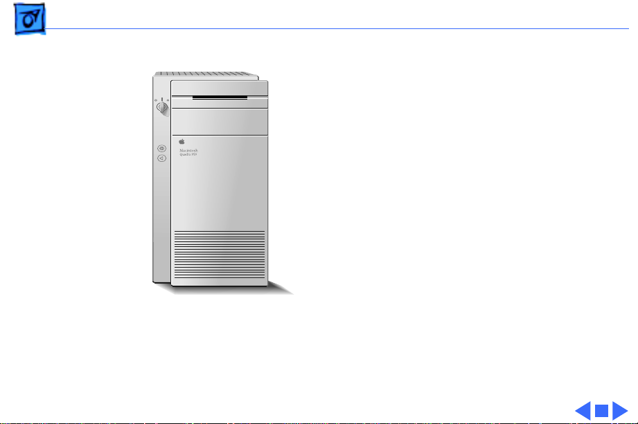
Basics Overview - 2
Overview
This manual includes
complete repair procedures
for the Quadra 900/950 and
the Apple Workgroup Server
95, pictured at left.
Figure: Macintosh Quadra 900/950 and AWS 95
Page 4

K
Service Source
Specifications
Macintosh Quadra 900/950/AWS
95
Page 5

Specifications Processor - 1
Processor
CPU
Quadra 900:
Quadra 950 and AWS
95:
Addressing
Motorola 68040 microprocessor
Built-in paged memory management unit (PMMU), floating-point
unit (FPU), and 8K memory cache
25 MHz
33 MHz
32-bit registers
32-bit address bus
32-bit data bus
Page 6

Specifications Memory - 2
Memory
RAM
Quadra 900
Quadra 950
AWS 95
ROM
PRAM
4 MB standard, expandable to 256 MB (80 ns or faster
SIMMs)
8 MB standard, expandable to 256 MB (80 ns or faster
SIMMs)
16 MB, 32 MB, or 48 MB parity RAM standard, expandable to
256 MB (80 ns or faster 9-bit SIMMs)
1 MB, using two 150 ns, 256K by 16-bit chips
256 bytes of parameter memory
Page 7

Specifications Memory - 3
VRAM
Clock/Calendar
1 MB, expandable to 2 MB (100 ns or faster VRAM SIMMs) by
installing four 256K or two 512K SIMMs
ASIC clock chip with PRAM and DFAC support and seven-year
lithium battery
Page 8

Specifications Disk Storage - 4
Disk Storage
Floppy Drive
Hard Drive
Quadra 900 and 950
AWS 95
Internal, 1.4 MB Apple SuperDrive
230, 500, or 1000 MB hard drive (optional)
230, 500, 1000, or 2000 MB hard drive; comes in either a two-
drive or five-drive configuration
Note
: Refer to Take Apart for more information on the twodrive configuration and to Additional Procedures for more
information on the five-drive configuration.
Page 9

Specifications Disk Storage - 5
DDS-DC Drive
2 GB digital data storage-data compression drive for 4 mm tape
backup; available as an upgrade on the Quadra 900 and 950;
optional on the AWS 95
Page 10

Specifications I/O Interfaces - 6
I/O Interfaces
SCSI
Quadra 900
AWS 95 and Quadra
900/950 (with PDS
card upgrade)
Apple Desktop Bus
One external SCSI port; DB-25 connector
One internal SCSI port with 50-pin IDC connector; Supports a
maximum of eight devices (including the computer, which is
always device 7)
Two internal SCSI ports with 50-pin IDC connectors; Two
external SCSI ports with DB-25 connectors; Supports a
theoretical limit of 20 devices (including the computer, which
is always device 7) on four separate SCSI buses (two internal
and two external); Macintosh Operating System supports only
7 devices
One Apple Desktop Bus (ADB) port; low-speed, synchronous
serial interface
Page 11

Specifications I/O Interfaces - 7
NuBus
Expansion
Serial
Sound
Five slots support standard and oversize cards, burst-mode
transfers, a processor write buffer, and NuBus '90; 96-pin
Euro-DIN connectors
One 68040 processor-direct slot (PDS) with 140-pin connector
Two RS-232/RS-422 ports with mini DIN-8 connectors;
230.4 Kbits/sec. maximum; 0.920 Mbits/sec. if external clock
source is provided (modem interface only)
Asynchronous, synchronous (modem only), and AppleTalk
(printer only) protocols supported
8-bit stereo output; 8-bit monoaural input
Supports electret-type microphone
Page 12

Specifications I/O Interfaces - 8
Video
Ethernet
Supports Apple monitors (8-bit), VGA monitors, and NTSC and
PAL video standards
One Ethernet port, AUI-15 connector
Page 13

Specifications Sound and Video - 9
Sound and Video
Video Display
Sound Generator
Microphone
Built-in 8-bit video circuitry (upgradeable to 24-bit)
Supports Apple 8-bit monitors and many non-Apple monitor
types (NTSC, PAL, VGA)
Four-voice, wavetable synthesis
Stereo sampling generator
Electret, omnidirectional; output voltage is 4 mV, peak to peak,
at normal value
Page 14

Specifications Electrical - 10
Electrical
Line V oltage
Line Frequency
Maximum Power
100–240 VAC (RMS), self-configuring power supply
50–60 Hz, single phase
303 W (not including monitor)
Page 15

Specifications Physical - 11
Physical
Dimensions
Weight
Height: 16.8 in. (473 mm)
Width: 8.9 in. (224 mm)
Depth: 20.6 in. (523 mm)
36 lb., 12 oz. (16.7 kg) without hard drive
Page 16

Specifications Environmental - 12
Environmental
Operating Temp
Storage Temp
Relative Humidity
Altitude
50–104° F (10–40° C)
–40 to 116.6° F (–40 to 47° C)
20–80% noncondensing
0–10,000 ft. (0–3048 m)
Page 17

K
Service Source
Troubleshooting
Macintosh Quadra 900/950/AWS
95
Page 18

Troubleshooting General - 1
General
The Symptom Charts included in this chapter will help you
diagnose specific symptoms related to your product. Because cures
are listed on the charts in the order of most likely solution, try
the first cure first. Verify whether or not the product continues to
exhibit the symptom. If the symptom persists, try the next cure.
(Note: If you have replaced a module, reinstall the original module
before you proceed to the next cure.)
If you are not sure what the problem is, or if the Symptom Charts
do not resolve the problem, refer to the Flowchart for the product
family.
For additional assistance, contact Apple Technical Support.
Page 19

Troubleshooting General - 2
Error Chords
One-part error
chord sounds during
startup sequence
Two-part error chord
sounds during
startup sequence
1 Disconnect SCSI data cable from logic board and reboot
system. If startup sequence is normal, initialize hard drive.
If error chord still sounds, replace hard drive.
2 Disconnect floppy drive cable connector and reboot system. If
startup sequence is normal, replace floppy drive.
3 Replace logic board. Retain customer's SIMMs.
Perform SIMM verification. Refer to Memory manual.
Page 20

Troubleshooting General - 3
System Problems
Does not power on;
screen is black, fan is
not running, and LED
is not lit
Clicking, chirping,
or thumping
1 Check power cables.
2 Plug monitor directly into wall socket and verify that
monitor has power.
3 Replace power cord.
4 Replace power supply.
5 Replace logic board. Retain customer's SIMMs.
1 Replace power supply.
2 Replace logic board. Retain customer's SIMMs.
3 Replace floppy drive cable.
4 Replace floppy drive.
Page 21

Troubleshooting General - 4
System shuts down
intermittently
System Problems
1 Make sure air vents on side and rear of computer are clear.
Thermal protection circuitry may shut down system. After
30 to 40 minutes, system should be OK.
2 Replace power cord.
3 Check battery. Refer to "Battery Verification" in Additional
Procedures.
4 Replace power supply.
5 Replace logic board. Retain customer's SIMMs.
(Continued)
Page 22

Troubleshooting General - 5
System
intermittently
crashes or hangs
System Problems
1 Verify that system software is correct version.
2 Verify that software is known-good.
3 Verify that software is System 7 compatible.
4 Clear parameter RAM. Hold down <Command> <Option> <P>
<R> during startup but before "Welcome To Macintosh"
appears.
5 Replace SIMMs. Refer to Memory manual.
6 Replace logic board. Retain customer's SIMMs.
7 Replace power supply.
(Continued)
Page 23

Troubleshooting General - 6
Video
Screen is black, audio
and drive operate, fan
is running, and LED is
lit
1 Adjust brightness on monitor.
2 Replace monitor. Refer to appropriate monitor manual to
troubleshoot defective monitor.
3 Replace video cable.
4 If a video interface card is installed, move it to a different
slot.
5 Replace video interface card, if installed.
6 Clear parameter RAM. Hold down <Command> <Option> <P>
<R> during startup but before "Welcome To Macintosh"
appears.
7 Replace SIMMs. Refer to Memory manual.
8 Replace logic board. Retain customer's SIMMs.
9 Replace power supply.
Page 24

Troubleshooting General - 7
Screen is black, audio
and drive do not
operate, but fan is
running and LED is lit
Video
1 Replace video cable.
2 If a video interface card is installed move it to a different
3 Replace video interface card, if installed.
4 Replace SIMMs. Refer to Memory manual.
5 Replace logic board. Retain customer's SIMMs.
6 Replace power supply.
(Continued)
slot.
Page 25

Troubleshooting General - 8
Partial or whole
screen is bright and
audio is present, but
no video information
is visible
Video
1 Replace monitor. Refer to appropriate monitor manual to
2 Replace video cable.
3 If a video interface card is installed, move it to a different
4 Replace video interface card, if installed.
5 Clear parameter RAM. Hold down <Command> <Option> <P>
6 Replace logic board. Retain customer's SIMMs.
(Continued)
troubleshoot defective monitor.
slot.
<R> during startup but before "Welcome To Macintosh"
appears.
Page 26

Troubleshooting General - 9
Floppy Drive
Internal floppy drive
does not operate
During system
startup, disk ejects;
display shows icon
with blinking "X"
1 Verify that keyswitch is not set to secure.
2 Replace disk with known-good disk.
3 Replace floppy drive cable.
4 Replace internal floppy drive.
5 Replace logic board. Retain customer's SIMMs.
6 Replace power supply.
1 Replace disk with known-good system disk.
2 Clear parameter RAM. Hold down <Command> <Option> <P>
<R> during startup but before "Welcome To Macintosh"
appears.
3 Replace floppy drive cable.
4 Replace internal floppy drive.
5 Replace logic board. Retain customer's SIMMs.
Page 27

Troubleshooting General - 10
Floppy Drive
Does not eject disk 1 Verify that keyswitch is not set to secure.
2 Switch off computer. Hold mouse button down while you
switch computer on.
3 Replace internal floppy drive.
4 Replace floppy drive cable.
5 Replace logic board. Retain customer's SIMMs.
Attempts to eject
disk, but doesn't
1 Push disk completely in.
2 Reseat floppy drive bezel and drive so bezel slot aligns
correctly with drive.
3 Eject disk manually.
4 Replace floppy drive.
(Continued)
Page 28

Troubleshooting General - 11
Internal floppy drive
runs continuously
MS-DOS drive does
not recognize a disk
formatted on a 1.4 MB
drive
Floppy Drive
1 Replace disk with known-good system disk.
2 Replace floppy drive cable.
3 Replace internal floppy drive.
4 Replace logic board. Retain customer's SIMMs.
To read and write files with either MS-DOS or 1.4 MB drive,
format all disks with MS-DOS drive first.
(Continued)
Page 29

Troubleshooting General - 12
Hard Drive
Single internal hard
drive will not
operate; drive doesn't
spin
No internal hard
drives operate
1 Replace hard drive data cable.
2 Replace hard drive power cable.
3 Replace hard drive.
1 Verify there are no duplicate SCSI device addresses.
2 Replace hard drive data cable.
3 Replace power supply.
4 Replace logic board. Retain customer's SIMMs.
Page 30

Troubleshooting General - 13
Drive does not appear
on the desktop
Works with internal
or external SCSI
devices but not with
both
Hard Drive
1 Verify there are no duplicate SCSI device addresses.
2 Update the SCSI device driver using Apple HD SC Setup. Run
Disk First Aid to verify the condition of the drive's directory
structure.
3 Replace the SCSI hard drive cable.
4 If drive is not initialized, use HD SC Setup to initialize.
5 Replace with known good hard drive. If the hard drive still
doesn't work, switch back to the original hard drive and
replace the logic board.
1 Verify there are no duplicate SCSI device addresses.
2 Replace terminator on external device.
3 Make sure internal hard drives are not terminated.
4 Refer to appropriate manual to troubleshoot defective
external device.
(Continued)
Page 31

Troubleshooting General - 14
Peripheral
Cursor does not move 1 Verify that keyswitch is not set to secure.
2 Check mouse connection.
3 Inspect inside of mouse for buildup of dirt or other
contaminants. Clean mouse if necessary.
4 If mouse was connected to keyboard, connect it to a computer
ADB port instead. If mouse works, replace keyboard.
5 If mouse does not work in any ADB port on computer, replace
mouse.
6 Replace logic board. Retain customer's SIMMs.
Cursor moves, but
clicking mouse
button has no effect
1 Replace mouse.
2 Replace logic board. Retain customer's SIMMs.
Page 32

Troubleshooting General - 15
Double-click doesn't
open application,
disk, or server
Peripheral
1 Remove duplicate system files from hard drive.
2 Clear parameter RAM. Hold down <Command> <Option> <P>
<R> during startup but before "Welcome To Macintosh"
appears. Reset mouse controls.
3 If mouse was connected to keyboard, connect mouse to
computer ADB port instead. If mouse works, replace
keyboard.
4 If mouse does not work in any ADB port on computer, replace
mouse.
5 Replace logic board. Retain customer's SIMMs.
(Continued)
Page 33

Troubleshooting General - 16
No response to any
key on keyboard
Known-good serial
printer will not print
Known-good printer
on AppleTalk network
will not print
Peripheral
1 Verify that keyswitch is not set to secure.
2 Check keyboard connection to ADB port.
3 Replace keyboard cable.
4 Replace keyboard.
5 Replace logic board. Retain customer's SIMMs.
1 Verify that system software is 7.0.1 or later.
2 Make sure Chooser and Control Panel settings are correct.
3 Replace printer interface cable.
4 Replace logic board. Retain customer's SIMMs.
1 Verify that system software is 7.0.1 or later.
2 Make sure Chooser and Control Panel settings are correct.
(Continued)
Page 34

Troubleshooting General - 17
Miscellaneous
No sound from
speaker
1 Verify that volume setting in Control Panel is 1 or above.
2 Replace speaker.
3 Replace logic board. Retain customer's SIMMs.
Page 35

K
Service Source
T ak e Apart
Macintosh Quadra 900/950/AWS
95
Page 36

Take Apart Cover - 1
Cover
No preliminary steps are
required before you begin
this procedure.
1 Press the two latches,
lift the cover, and
remove it from the
computer.
Note
: You must place the
system on its side.
Attempting to remove the
cover with the system
standing may cause
damage to the cover.
Page 37

Take Apart Drive Shelf - 2
Drive Shelf
Drive Shelf
Before you begin, remove
the cover.
Caution:
precautions in Bulletins/
Safety.
Note
Five-Drive configuration,
refer to Additional
Procedures.
Review the ESD
: For information on the
Page 38

Take Apart Drive Shelf - 3
SCSI Power Cable
Floppy Drive
Cable
SCSI Data
Cable
1 Disconnect the floppy
drive cable and SCSI
data cable from the logic
board.
Note
: The SCSI data cable
is connected to the PDS
card in the Apple
Workgroup Server 95.
2 Disconnect the SCSI
power cable from the
power supply.
Page 39

Take Apart Drive Shelf - 4
3 Remove the two drive
Drive Shelf
Screws
shelf screws.
4 Slide the drive shelf
toward the rear of the
computer.
Page 40

Take Apart Drive Shelf - 5
5 Grasp the cable tie and
Cable Tie
the metal tab and lift the
drive shelf out of the
computer, being careful
that none of the cables
catch on the case.
Metal
Tab
Page 41

Take Apart Floppy Drive - 6
Floppy Drive
Floppy Drive
Before you begin, remove
the following:
• Cover
• Drive shelf
Page 42

Take Apart Floppy Drive - 7
1 Disconnect the floppy
drive cable from the
Screw
Floppy Drive
Cable
floppy drive.
2 Remove the floppy drive
mounting screw and
spacer.
Spacer
Page 43

Take Apart Floppy Drive - 8
3 Lift the rear of the
floppy drive and slide it
off the drive shelf.
Replacement Note
recommends using dust
shields on 1.4 MB
SuperDrives in Quadra 900
computers. All 1.4 MB
replacement drives ship
with the dust shield already
installed. If you plan to
install a dust shield on the
current drive, you must
first clean the drive.
: Apple
Page 44

Take Apart Hard Drive - 9
Hard Drive
Hard Drive
Before you begin, remove
the following:
• Cover
• Drive shelf
• Floppy drive
Page 45

Take Apart Hard Drive - 10
Drive Carrier
Carrier
Mounting Screw
SCSI
Data Cable
SCSI Power
Cable
1 Disconnect the SCSI data
cable and power cable
from the hard drive.
2 Remove the hard drive
mounting screw.
3 Lift the hard drive, along
with its carrier, from
the drive shelf.
Replacement Note:
For
information on removing the
hard drive from the carrier
and returning drives,
cables, and carriers to
Apple, refer to the Parts
chapter in this manual.
Page 46

Take Apart DDS-DC Tape Drive - 11
DDS-DC Tape Drive
DDS-DC Tape
Drive
Before you begin, remove
the following:
• Cover
• Drive shelf
• Floppy drive
Page 47

Take Apart DDS-DC Tape Drive - 12
Drive Carrier
Carrier Mounting Screw
SCSI Data Cable
Power
Cable
1 Disconnect the SCSI data
cable and power cable
from the tape drive.
2 Remove the carrier
mounting screw.
Page 48

Take Apart DDS-DC Tape Drive - 13
Drive Carrier
Carrier Mounting Screw
SCSI Data Cable
Power
Cable
3 Lift the tape drive,
along with its carrier,
from the drive shelf.
Replacement Note:
For
information on removing the
tape drive from the carrier
and returning drives,
cables, and carriers to
Apple, refer to the Parts
chapter in this manual.
Page 49

Take Apart Speaker Bezel and Speaker - 14
Speaker
Speaker Bezel and Speaker
Before you begin, remove
the following:
• Cover
• Drive shelf
Page 50

Take Apart Speaker Bezel and Speaker - 15
1 Disconnect the speaker
Speaker Cable Speaker Bezel
cable from the logic
board.
2 Release the four plastic
latches on the inside of
the speaker bezel.
3 Remove the speaker
bezel and speaker from
the computer.
Power
Supply
Page 51

Take Apart Speaker Bezel and Speaker - 16
4 Remove the two screws
and lift the speaker off
the speaker bezel.
Page 52

Take Apart Power Supply - 17
Power Supply
Power Supply
Before you begin, remove
the following:
• Cover
• Drive shelf
• Speaker bezel
Page 53

Take Apart Power Supply - 18
1 Disconnect the power
supply cable from the
Power Supply Cable
logic board.
2 Remove the three power
supply mounting screws.
Power Supply
Page 54

Take Apart Power Supply - 19
Bezel
3 Release the two plastic
latches on the inside of
the blank bezel and
remove the bezel.
Latch
Latch
Page 55

Take Apart Power Supply - 20
4 Grasp the two handles
Handles
and, pulling evenly, lift
the power supply
straight up out of the
computer.
Page 56

Take Apart Fan - 21
Fan
Fan
Before you begin, remove
the following:
• Cover
• Drive shelf
• Speaker bezel
• Power supply
Page 57

Take Apart Fan - 22
Fan Cable
Fan
1 Disconnect the fan cable
from the power supply.
2 Remove the four fan
mounting screws.
3 Remove the fan and fan
grill from the power
supply.
Power Supply
Fan Grill
Page 58

Take Apart Workgroup Server PDS Card - 23
Workgroup Server PDS Card
Workgroup Server
PDS Card
Before you begin, remove
the cover
Caution:
the computer prior to
removing or installing the
Workgroup Server 95 PDS
card. Failure to unplug the
computer could cause damage
to the logic board and/or
card.
You must unplug
Page 59

Take Apart Workgroup Server PDS Card - 24
1 Disconnect the SCSI data
cable from the
Workgroup Server PDS
card.
SCSI Data
Cable
Page 60

Take Apart Workgroup Server PDS Card - 25
2
Caution
on both sides of the card
to avoid bending the
connector pins and
remove the card.
Note
the card by the metal
bracket.
: Pull up evenly
: Grasp the rear of
Replacement Caution:
replacing the card, do not
force it into the expansion
slot. If the card does not seat
properly, remove it and try
again.
When
Page 61

Take Apart Logic Board - 26
Logic Board
Before you begin, remove
the following:
• Cover
• Drive shelf
• Speaker bezel
• Power supply
• Expansion cards
Note
: The Quadra 900
contains a 25 MHz logic
board; the Quadra 950 and
AWS 95 contain a 33 MHz
board. Be sure to install the
Logic Board
correct board.
Page 62

Take Apart Logic Board - 27
Reset
Switch
Interrupt
Switch
Caution:
You must unplug
the computer prior to
removing expansion cards.
Failure to unplug the
computer could cause damage
to the logic board and/or
cards.
1 Press in on the sides of
the interrupt and reset
switches and push them
out of the case.
Page 63

Take Apart Logic Board - 28
2 Disconnect the
keyswitch cable from the
logic board.
3 Press down on the latch
and slide the logic board
toward the front of the
computer.
Latch
4 Lift the logic board,
front first, from the
computer.
Logic Board
Keyswitch
Cable
Replacement Note:
Remove
the SIMMs from the
defective logic board and
install them on the
replacement logic board.
(See the Memory manual.)
Page 64

K
Service Source
Upgrades
Macintosh Quadra 900/950/AWS
95
Page 65

Upgrades Expansion Cards - 1
Expansion Cards
Expansion Card
Before you begin, remove
the cover.
Caution:
the computer prior to
removing or installing
expansion cards. Failure to
unplug the computer could
cause damage to the logic
board and/or cards.
You must unplug
Page 66

Upgrades Expansion Cards - 2
1
Caution:
on both sides of the card
to avoid bending the
connector pins and
remove the card.
Note:
the card by the metal
bracket.
Pull up evenly
Grasp the rear of
Replacement Caution:
When replacing the card,
do not force it into the
expansion slot. If the
card does not seat
properly, remove it and
try again.
Page 67

Upgrades CD-ROM Upgrade - 3
CD-ROM
Drive
CD-ROM Upgrade
Before you begin, remove
the following:
• Cover
• Drive shelf
• Floppy drive
• Speaker bezel
Note:
Before installing the
CD-ROM drive, be sure to
remove any SCSI device
installed beneath the floppy
drive.
Page 68

Upgrades CD-ROM Upgrade - 4
1 Remove the blank bezel.
2 Install the slotted CD-
ROM drive bezel.
3 Reinstall the speaker
bezel.
Bezel
Latch
Latch
Page 69

Upgrades CD-ROM Upgrade - 5
4 Connect the audio and
Audio Cable
CD-ROM drive power
cables to the CD-ROM
drive.
Power Cable
Page 70

Upgrades CD-ROM Upgrade - 6
5 Install the CD-ROM
drive on the drive shelf
in the front position.
Floppy
Drive
Note
: Set the SCSI ID
number on the CD-ROM
drive. Make sure the ID
SCSI ID Select
Switch
CD-ROM
Drive
number is unique from
any other internal SCSI
device. Apple
recommends SCSI ID
number 5.
6 Reinstall the floppy
drive on the CD-ROM
drive carrier.
Drive
Shelf
7 Reinstall the drive shelf
and drives into the
computer.
Page 71

Upgrades CD-ROM Upgrade - 7
8 Remove the jumper at
connector J16 and
connect the audio cable to
Audio Cable
the logic board at that
location.
9 Reconnect the SCSI data
cable to all SCSI devices
10 Reconnect the SCSI
power cables to the
power supply.
Page 72

Upgrades Quadra 950 Upgrade - 8
Quadra 950 Upgrade
Before you begin, remove
the following:
• Cover
• Drive shelf
• Speaker bezel
• Power supply
• Expansion cards
• Logic board
Page 73

Upgrades Quadra 950 Upgrade - 9
Note:
A Macintosh Quadra
950 upgrade kit upgrades a
Macintosh Quadra 900 to a
Macintosh Quadra 950. The
upgrade kit includes a
Macintosh Quadra 950 logic
board and product labels.
Note
: After you perform a
Quadra 950 upgrade, the
system information
displayed by About This
Macintosh under the Apple
menu will still indicate a
Macintosh Quadra 900. You
must reinstall system
software to display the
correct system information.
Page 74

Upgrades Quadra 950 Upgrade - 10
1 Install the Macintosh
Quadra 950 logic board.
2 Replace all modules.
Logic Board
Page 75

Upgrades Quadra 950 Upgrade - 11
3 Peel off the backing from
the product label and
place the label on the
speaker bezel.
Label
Placement
Speaker
Bezel
Page 76

Upgrades Quadra 950 Upgrade - 12
4 Peel off the backing from
the product label and
place the label on the
rear bezel.
Label
Placement
Page 77

Upgrades AWS 95 Upgrade - 13
AWS 95 Upgrade
Workgroup
Server 95
PDS Card
Before you begin, remove
the cover.
Note
: A Workgroup Server
95 upgrade kit upgrades a
Macintosh Quadra 900 or
950 to a Workgroup Server
95. The upgrade kit
includes a processor-direct
slot (PDS) card and A/UX
3.0.1 and Retrospect
backup software on CDROM.
Caution:
the computer prior to
You must unplug
Page 78

Upgrades AWS 95 Upgrade - 14
installing or removing the
Workgroup Server 95 PDS
card. Failure to unplug the
computer could cause damage
to the logic board and/or
card.
1 Remove the plastic cover
plate behind the
processor-direct slot.
Plastic
Cover
Plate
Page 79

Upgrades AWS 95 Upgrade - 15
2 Disconnect the SCSI data
cable from the logic
board.
SCSI Data Cable
Page 80

Upgrades AWS 95 Upgrade - 16
3 Install the Workgroup
Workgroup Server 95
PDS Card
Server 95 PDS card in
the PDS slot.
PDS Slot
Replacement Caution
:
When installing the
card, do not force it into
the PDS slot. If the card
does not seat properly,
remove it and try again.
Page 81

Upgrades AWS 95 Upgrade - 17
4 Connect the SCSI data
cable to the 50-pin
connector at the top of
the Workgroup Server
SCSI Data
Cable
95 PDS card.
5 Install the A/UX 3.01
and Retrospect software.
Page 82

Upgrades AWS Cache Upgrade - 18
AWS Cache
Workgroup
Server 95
PDS Card
Upgrade
Before you begin, remove
the following:
• Cover
• WGS 95 PDS card
Note:
A Workgroup Server
PDS card cache upgrade
increases the amount of RAM
cache from 128K to 256K
or 512K.
Page 83

Upgrades AWS Cache Upgrade - 19
Workgroup
Server 95
PDS Card
Caution:
You must unplug
the computer prior to
removing or installing the
Workgroup Server 95 PDS
card. Failure to unplug the
computer could cause damage
to the logic board and/or
card.
Page 84

Upgrades AWS Cache Upgrade - 20
Install SIMMs as indicated.
• Upgrade from 128K to
256K:
– One 128K SRAM SIMM
– One TAG SIMM
• Upgrade from 128K to
TAG SIMM
128K SRAM SIMM
256K SRAM SIMM
512K:
– One 128K SRAM SIMM
– One 256K SRAM SIMM
– One TAG SIMM
Page 85

Upgrades Tape Drive Upgrade - 21
DDS-DC
Tape Drive
Tape Drive Upgrade
Before you begin, remove
the following:
• Cover
• Drive shelf
• Floppy drive
• Speaker bezel
Page 86

Upgrades Tape Drive Upgrade - 22
Note
: A DDS-DC drive
DDS-DC
Tape Drive
upgrade kit adds a digital
data storage–data
compression drive to a
Workgroup Server 95 or to
a Quadra 900 or Quadra 950
with the Workgroup Server
PDS card.
Note:
Before installing the
DDS-DC drive, be sure to
remove any SCSI device
installed beneath the floppy
drive.
Page 87

Upgrades Tape Drive Upgrade - 23
1 Install the DDS-DC tape
drive on the drive shelf
in the front position.
Note
: Set the SCSI ID
DDS-DC
Tape Drive
SCSI ID Switch
number on the DDS-DC
drive. Make sure the ID
number is unique from
any other internal SCSI
device. Apple
recommends SCSI ID
number 5.
Drive
Shelf
Page 88

Upgrades Tape Drive Upgrade - 24
2 Attach the floppy drive
on the carrier for the
DDS-DC tape drive.
Floppy
Drive
DDS-DC
Drive
Drive
Shelf
3 Reinstall the drive shelf
and drives into the
computer.
Page 89

Upgrades Tape Drive Upgrade - 25
4 Squeeze the two plastic
latches on the inside of
the blank bezel.
5 Remove the blank bezel
from the front of the
Blank Bezel
computer.
Latch
Latch
6 Install the DDS-DC drive
bezel.
7 Replace the speaker
bezel and cover.
Page 90

Upgrades Five-Drive Upgrade - 26
Five-Drive
Carrier
Hard Drive
Power
Cables
SCSI ID
Switch
SCSI Cable
Five-Drive Upgrade
Before you begin, remove
the existing drive shelf.
Page 91

Upgrades Five-Drive Upgrade - 27
Five-Drive
Carrier
Hard Drive
Power
Cables
SCSI ID
Switch
SCSI Cable
You will need the following
to ready the AWS 95 to hold
five drives:
• Five-drive carrier kit
• Five SCSI ID select
switches (part number
depends on drive type)
• Five-drive SCSI cable
with terminator
• Two hard drive power
cables with two drive
connectors each (each
cable connects up to two
hard drives)
• One hard drive power
cable with one drive
connector (already in
existing unit)
Page 92

Upgrades Five-Drive Upgrade - 28
1 Remove the two screws
that secure the top of the
new drive carrier to the
bottom piece.
2 Remove the top piece of
the drive carrier.
Page 93

Upgrades Five-Drive Upgrade - 29
There are five openings in
the bottom panel of the drive
SCSI ID
Switch
carrier for the SCSI ID
switches. The openings are
labeled A-E.
Note
: The type of SCSI ID
switch you install will
depend on the drive type.
3 To install the SCSI ID
switch for the first
drive, feed the
connector end of the SCSI
ID cable through the
opening labeled A on the
drive carrier.
EB DAC
Page 94

Upgrades Five-Drive Upgrade - 30
4 Push in on the SCSI ID
switch until it clicks
SCSI ID
Switch
into place.
5 Repeat this procedure to
install the remaining
SCSI ID switches.
EB DAC
Page 95

Upgrades Five-Drive Upgrade - 31
6 Connect the free end of
the first SCSI ID switch
cable to the first hard
drive, which you will be
E
D
C
B
A
installing in drive slot A.
Note
: When setting the
SCSI ID switches, make
sure no two peripherals,
including the DAT
player, are using the
same SCSI ID. Also, do
not set any of the SCSI ID
switches to 7.
Hard drives must be
installed in the fivedrive carrier in the
order shown (A–E).
Page 96

Upgrades Five-Drive Upgrade - 32
Note:
If you install
fewer than five drives,
you must still install the
drives in the order
E
D
C
B
A
shown.
Page 97

Upgrades Five-Drive Upgrade - 33
7 Remove the hard drives’
terminating resistors
before installation.
8 Install the first hard
drive in slot A (the
lower right slot) of the
drive carrier.
9 Insert the four screws
that secure the hard
drive to the drive
carrier. Tighten the
screws.
Follow this procedure to
install up to four additional
hard drives in the order
shown on the previous page.
Page 98

Upgrades Five-Drive Upgrade - 34
10 Once you have installed
all the hard drives,
replace the top of the
drive carrier.
11 Replace the two screws
that secure the top of the
drive carrier to the
bottom of the drive
carrier.
Caution
to pinch the cables that
run from the SCSI ID
select switches.
: Be careful not
Page 99

Upgrades Five-Drive Upgrade - 35
Drive B
Tape
Drive
Terminator
Drive D
Drive E
Not Used
Drive A
Drive C
PDS Connector
The SCSI cable connects up
to five hard drives and one
tape drive. The illustration
on this page indicates which
connectors attach to which
peripherals. The pull tabs
on the cable are marked as
illustrated.
Note
: Connect the tape drive
first. (See next page.)
Note
: If fewer than six
peripherals are present,
leave the connectors for the
missing peripherals
disconnected.
Page 100

Upgrades Five-Drive Upgrade - 36
Tape Drive
Connector
12 Attach the end of the SCSI
cable to the connector on
the tape drive (if
present).
13 Pull through the cable
that connects the floppy
drive (if present) to the
logic board so that the
cable will not obstruct
the insertion of the drive
carrier.
 Loading...