

Page 1

K
Service Source
Macintosh Portable
Page 2
K
Service Source
Basics
Macintosh Portable
Page 3
Basics Overview - 1
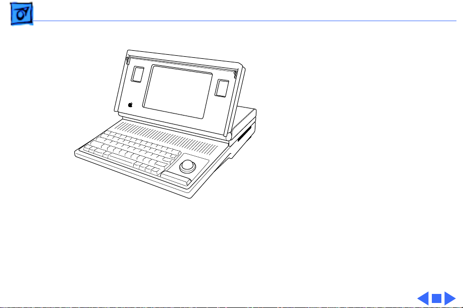
Overview
This manual contains
complete repair procedures
for the Macintosh Portable
shown at left.
Figure: Macintosh Portable
Page 4

K
Service Source
Specifications
Macintosh Portable
Page 5

Specifications Processor - 1
Processor
CPU
Addressing
Wait States
Motorola 68HC000, 16-bit CMOS microprocessor
15.6672 MHz
32-bit internal registers
24-bit address bus
16-bit data bus
1 (static logic board)
10 (pseudostatic logic board)
Page 6

Specifications Memory - 2
Memory
RAM
ROM
PRAM
VRAM
1 MB using thirty-two 32K by 8-bit static RAM chips; 100 ns
access time; addressing supports up to 9 MB
Expandable to 2 MB with optional 1 MB RAM expansion card
Expandable to 4 MB with optional 3 MB RAM expansion card
(backlit model)
256K using two 128K by 8-bit devices; 150 ns access time;
addressing supports up to 4 MB
128 bytes of system parameter memory
32K of static video display memory
Page 7

Specifications Disk Storage - 3
Disk Storage
Floppy Drive
Hard Drive
Internal 1.4 MB floppy drive
Internal 40 MB hard drive (optional)
Page 8

Specifications I/O Interfaces - 4
I/O Interfaces
Floppy Drive
SCSI
Apple Desktop Bus
Serial
Modem
DB-19 connector
Supports Macintosh 800K Disk Drive, Apple 3.5 Drive, Apple
SuperDrive, and Apple Hard Disk 20
1.5 MB/second transfer rate
Supports a maximum of eight devices
Low-speed serial interface
Supports optional low-power mouse
Two RS-422 serial ports; mini DIN-8 connectors
Phone jack for optional external modem
Page 9

Specifications I/O Interfaces - 5
Power Adapter
Sound
Video
Power adapter port
Stereo sound-in port
DA-15 connector
Supports the connection of external video devices
Page 10

Specifications I/O Devices - 6
I/O Devices
Keyboard
Low-Power ADB Mouse
Trackball
63 keys
N-key rollover
Apple Desktop Bus (ADB) interface
US, British, French Canadian, Japanese, German, Spanish,
French, Swedish, and Italian versions available
Low-power version of the ADB mouse
Opto-mechanical type
ADB interface
ADB interface
Page 11

Specifications I/O Devices - 7
Numeric Keypad (Optional)
18 keys
ADB interface
US, Pacific, and European versions available
Page 12

Specifications Sound and Video - 8
Sound and Video
Sound Generator
Video Display
Apple Sound Chip
One-or four-voice mono (one or two voices in stereo) with 4-bit
digital-to-analog conversion using a 22-kHz sampling rate
Filtered by two Sony sound chips
10-in. (diagonal) screen
Reflective, active-matrix, liquid crystal, flat-panel display
640 by 400 pixels, 75 dpi
.28 mm dot size; .33 mm dot pitch; 80% active area
Variable tilt
Contrast (nonbacklit display) and brightness (backlit display) is
software adjustable using the Control Panel.
Page 13

Specifications Electrical - 9
Electrical
Main Battery
Backup Battery
Power Adapter
Input voltage:
Output voltage:
Sealed lead-acid
6.5 V
Up to 10 hours (fully charged battery); time depends on system
configuration and power management settings
9 V transistor
85–270 VAC (100/240 nominal), 48–62 Hz (50/60 nominal)
7.0–7.6 V (7.5 nominal), 5 mA–2.0 A (1.5 nominal)
US, Japanese, United Kingdom, Australian, and European versions
Page 14

Specifications Electrical - 10
Battery Recharger (Optional)
Input voltage: 7.5 VAC
Battery recharger output voltage: 6.5 VDC
Page 15

Specifications Physical - 11
Physical
Dimensions (Display Open)
Weight (With Battery)
Width: 15.25 in. (387.35 mm)
Height: 11.0 in. (279.4 mm)
Depth: 14.83 in. (365.25 mm)
Height at rear panel: 4.05 in. (102.87 mm)
Height at front panel: 2.10 in. (53.34 mm)
13.75 lb. (6.25 kg) without hard drive
15.75 lb. (7.16 kg) with hard drive
Page 16

K
Service Source
Troubleshooting
Macintosh Portable
Page 17

Troubleshooting General - 1
General
The Symptom Charts included in this chapter will help you
diagnose specific symptoms related to your product. Because cures
are listed on the charts in the order of most likely solution, try
the first cure first. Verify whether or not the product continues to
exhibit the symptom. If the symptom persists, try the next cure.
(Note: If you have replaced a module, reinstall the original module
before you proceed to the next cure.)
If you are not sure what the problem is, or if the Symptom Charts
do not resolve the problem, refer to the Flowchart for the product
family.
For additional assistance, contact Apple Technical Support.
Page 18

Troubleshooting Symptom Charts/Power - 2
Symptom Charts
Power
Screen is blank;
computer is not
responding
1 If computer is new, remove plastic sheet from between
battery and contacts.
2 Reset power manager.
3 Connect power adapter and restart computer in three or four
minutes.
4 Replace main battery.
5 Check keyboard cable connections.
6 Replace keyboard.
7 Replace keyboard cable.
8 Replace logic board. Retain customerÕs SIMMs.
Page 19

Troubleshooting Symptom Charts/Power
(Continued)
- 3
After main battery is
removed, some
Control Panel settings
are different
Power adapter is
plugged in and
connected; battery DA
does not indicate
charger is connected
Power
1 Did you replace battery cover after removing main battery?
2 Replace backup battery.
1 Verify that charger is connected properly.
2 Replace main battery.
3 Replace power adapter.
4 Replace logic board. Retain customerÕs SIMMs.
(Continued)
If so, power interruption destroyed settings. Restore
contents of Control Panel.
Page 20

Troubleshooting Symptom Charts/Power
(Continued)
- 4
Low-power warning
appears soon after
you start to use
computer
Battery does not
retain charge, even
when computer is not
in use
Power
1 Attach power adapter.
2 Make sure peripherals display low-power icon.
3 Reduce use of power-consuming devicesÑfor example, floppy
1 Upgrade to system software 6.0.5 or later.
2 Replace battery.
3 Replace keyboard.
4 Replace wire harness assembly.
5 Replace logic board.
(Continued)
drive, hard drive, modem, and speakerÑor connect power
adapter.
Page 21

Troubleshooting Symptom Charts/Video - 5
Video
Some pixels never
come on; no pattern
Some pixels are
always black; no
pattern
Row of pixels is
always black
Row of pixels never
blackens
If display contains six or more voids, replace LCD display.
Maximum of five permanently OFF pixels (voids) is acceptable.
If any pixel is on constantly, replace LCD display.
1 Replace LCD display.
2 Replace display cable.
3 Replace logic board. Retain customerÕs SIMMs.
1 Replace LCD display.
2 Replace display cable.
3 Replace logic board. Retain customerÕs SIMMs.
Page 22

Troubleshooting Symptom Charts/Video
(Continued)
- 6
Video
Display is blurred 1 Adjust angle of display.
2 Use Control Panel to adjust screen contrast.
Display is too dark 1 Move computer closer to direct light or move light source
2 Use Control Panel to adjust screen contrast.
3 Replace LCD display.
4 Replace logic board. Retain customerÕs SIMMs.
Display is too light 1 Adjust angle of display.
2 Use Control Panel to adjust screen contrast.
3 Replace LCD display.
(Continued)
closer to computer.
Page 23

Troubleshooting Symptom Charts/Video
(Continued)
- 7
Backlight level cannot
be changed
Backlight does not
operate
Display is blank,
though computer
appears to operate
correctly
Video
Use version 1.3 of Portable CDEV.
1 Use version 1.3 of Portable CDEV.
2 Check inverter PCA connections.
3 Replace inverter PCA. Refer to ÒLCD Display (Backlit)Ó in
4 Replace LCD Display.
5 Replace logic board. Retain customerÕs SIMMs.
1 Check display cable connection.
2 Replace LCD display.
3 Replace display cable.
4 Replace logic board. Retain customerÕs SIMMs.
(Continued)
Take Apart.
Page 24

Troubleshooting Symptom Charts/Floppy Drive - 8
Floppy Drive
Audio and video are
present, but internal
drive does not operate
Disk ejects while
booting; display
shows Mac icon with
blinking ÒXÓ
1 Replace floppy disk.
2 Replace floppy drive.
3 Replace floppy drive cable.
4 Replace logic board. Retain customerÕs SIMMs.
1 Replace bad system disk with known good.
2 Replace floppy drive.
3 Replace floppy drive cable.
4 Replace logic board. Retain customerÕs SIMMs.
Page 25

Troubleshooting Symptom Charts/Floppy Drive
(Continued)
- 9
Floppy Drive
Disk does not eject 1 Shut down computer, press and hold trackball or mouse
button, and switch on computer.
2 Eject disk manually by pushing opened paper clip into hole
near drive.
3 Replace floppy drive.
4 Replace floppy drive cable.
5 Replace logic board. Retain customerÕs SIMMs.
Disk initialization
fails
1 Verify that disk is Apple-certified.
2 Replace floppy disk.
3 Replace floppy drive.
4 Replace logic board. Retain customerÕs SIMMs.
(Continued)
Page 26

Troubleshooting Symptom Charts/Hard Drive - 10
Hard Drive
Internal hard drive
does not operate
1 Switch on external SCSI devices connected to Portable.
2 Check hard drive cable connection.
3 Use HD SC Setup to see whether drive is visible. If it is,
reinitialize drive.
4 Replace hard drive.
5 Replace logic board. Retain customerÕs SIMMs.
Page 27

Troubleshooting Symptom Charts/Peripherals - 11
Peripherals
After external SCSI
device is connected,
computer no longer
boots
Cursor does not move
when you use
trackball
1 Switch on external SCSI device before starting computer.
2 Verify that cable termination is correct.
3 Verify that no two SCSI devices have same device address.
4 Replace logic board. Retain customerÕs SIMMs.
1 Reset power manager.
2 Check cable connections between trackball and logic board.
3 Replace trackball cable.
4 Replace trackball.
5 Replace logic board. Retain customerÕs SIMMs.
Page 28

Troubleshooting Symptom Charts/Peripherals
(Continued)
- 12
Cursor intermittently
does not move or
moves erratically
Cursor does not move
when you use mouse.
Cursor moves, but
clicking button has no
effect
Peripherals
1 Clean trackball ball and internal rollers.
2 Replace trackball.
1 Check mouse connection to ADB port.
2 Reset power manager.
3 Clean mouse ball and inside mouse.
4 Replace mouse.
5 Replace logic board. Retain customerÕs SIMMs.
1 If trackball button isnÕt working, replace trackball cable. If
mouse button doesnÕt work, replace mouse.
2 Replace trackball ball.
3 Replace logic board. Retain customerÕs SIMMs.
(Continued)
Page 29

Troubleshooting Symptom Charts/Peripherals
(Continued)
- 13
No response to any
key on keyboard
Known-good
ImageWriter,
ImageWriter II, or LQ
doesnÕt print
Known-good
LaserWriter doesnÕt
print
Peripherals
1 Reset power manager by pressing reset and interrupt
switches simultaneously.
2 Check keyboard connection to logic board.
3 Replace keyboard.
4 Replace logic board. Retain customerÕs SIMMs.
1 Verify that System is 6.0.5 or later.
2 Verify Chooser settings.
3 Replace printer cable.
4 Replace logic board. Retain customerÕs SIMMs.
1 Verify that System is 6.0.5 or later.
2 Verify Chooser settings.
3 Replace printer. If new printer works, computer is OK.
4 Replace logic board. Retain customerÕs SIMMs.
(Continued)
Page 30

Troubleshooting Symptom Charts/Peripherals
(Continued)
- 14
Device connected to
modem port doesnÕt
work
Serial devices are
unrecognized or
garbage is
transmitted and/or
received
Peripherals
1 Verify that External Modem is selected in the Portable CDEV.
2 Verify that System is 6.0.5 or later.
3 Replace logic board. Retain customerÕs SIMMs.
1 Use version 1.0 of Portable INIT.
2 Upgrade to system software 6.0.5 or later.
(Continued)
Page 31

Troubleshooting Symptom Charts/Peripherals
(Continued)
- 15
When using an
external modem: after
exiting a
communication
application and
putting the computer
to sleep three or four
times, the computer
freezes when it comes
out of system sleep
Peripherals
Upgrade to system software 6.0.5 or later.
(Continued)
Page 32

Troubleshooting Symptom Charts/Internal Modem - 16
Internal Modem
Internal modem
options do not appear
in Portable CDEV
when modem is
installed
Modem does not
respond properly to
AT instructions
Modem interferes
with system sound
1 Reseat modem card.
2 Replace modem card.
3 Replace logic board. Retain customerÕs SIMMs.
1 Verify that baud rate and data format settings of
communications application are compatible with Portable
Data Modem 2400 and remote modem.
2 Replace modem card.
1 Replace modem card.
2 Replace logic board. Retain customerÕs SIMMs.
Page 33

Troubleshooting Symptom Charts/Internal Modem
(Continued)
- 17
Modem does not
respond to incoming
call
Modem has no sound
output
Internal Modem
1 If system doesnÕt respond to incoming call during sleep mode,
select When Phone Rings option in Automatic Wake-up
section of Portable CDEV .
2 Replace modem card.
3 Replace logic board. Retain customerÕs SIMMs.
Replace modem card.
(Continued)
Page 34

Troubleshooting Symptom Charts/Miscellaneous - 18
Miscellaneous
Screen goes blank and
computer shuts down
every few minutes
Some applications
seem to run slower
after few seconds
Hard disk is slow to
respond, or screen
goes blank too often
Adjust sleep delay in Control Panel or connect power adapter.
Disable system rest.
Adjust sleep delay in Control Panel or connect power adapter.
Page 35

Troubleshooting Symptom Charts/Miscellaneous
(Continued)
- 19
Miscellaneous
Speaker doesnÕt work 1 Verify that volume setting in Control Panel is 1 or above.
2 Check speaker connection to logic board.
3 Replace speaker.
4 Replace logic board. Retain customerÕs SIMMs.
Screen suddenly goes
blank
Error chords sound
during startup
Press any key except Caps Lock.
Replace logic board. Retain customerÕs SIMMs.
(Continued)
Page 36

Troubleshooting Symptom Charts/Macintosh Portable Startup Problems
Macintosh Portable Startup Problems Flowchart 1
START
Reset power
manager.
Turn on system without
startup disk (press any key
except <Caps Lock>).
Do
startup tones
sound?
Yes
Is
startup tone
normal?
Yes
Is gray
pattern
displayed?
Yes
1
No
No
No
Is any
video
displayed?
1. Replace speaker.
2. Replace logic board.
Replace logic board.
1. Verfiy that display
cable is connected.
2. Replace LCD display.
3. Replace display cable.
4. Replace logic board.
Yes
No
1. Replace keyboard.
2. Replace keyboard cable.
3. Replace logic board.
Go to Start
Page 37

Troubleshooting Symptom Charts/Macintosh Portable Startup Problems
Macintosh Portable Startup Problems Flowchart 2
1
Is
disk icon
with question
mark
displayed?
Yes
Insert System Tools
in floppy drive.
No
Replace logic board.
Go to Start
Does
desktop
appear?
Yes
Do
trackball and
button function
correctly?
Yes
END
Do
No
No
you hear
sounds from
disk drive?
Yes
1. Use known-good startup disk.
2. Replace disk drive.
3. Replace disk drive cable.
4. Replace logic board.
1. Reset power manager.
2. Replace trackball.
3. Replace trackball cable.
4. Replace logic board.
1. Replace keyboard.
No
2. Replace keyboard cable.
3. Replace logic board.
Go to Start
Page 38

K
Service Source
T ak e Apart
Macintosh Portable
Page 39

Take Apart Rear Cover - 1
Rear Cover
No preliminary steps are
required before you begin
this procedure.
Rear Cover
Review the ESD precautions
in Bulletins/Safety.
Page 40

Take Apart Rear Cover - 2
Press the two plastic cover
latches, pivot the rear of the
cover up, and lift off the
rear cover.
Rear Cover
Page 41

Take Apart Keyboard Cover - 3
Keyboard Cover
No preliminary steps are
required before you begin
Keyboard
Cover
this procedure.
Review the ESD precautions
in Bulletins/Safety.
1 Push the carrying handle
toward the computer and
open the display.
Page 42

Take Apart Keyboard Cover - 4
2 Position the computer
upright on the rear
panel.
3 Insert the tip of a
screwdriver under the
center of each foot;
gently lift the foot away
from the case and
Foot
remove it.
Page 43

Take Apart Keyboard Cover - 5
4 Insert a jeweler’s
screwdriver into the
center hole at the topright corner of the
bottom case. Push in the
screwdriver and unsnap
the corner of the
keyboard cover.
5 Repeat this step to
unsnap the left corner
of the keyboard cover.
Page 44

Take Apart Keyboard Cover - 6
6 Place the computer flat
on the grounded surface.
7 Starting at the edges and
working toward the
center, slide your index
fingers between the
bottom case and the
keyboard cover until the
cover releases.
Note:
Two latches attach the
center of the cover to the
bottom case, so you’ll feel
some resistance as you lift
the center cover.
Page 45

Take Apart Main Battery - 7
Main Battery
Before you begin, remove
the rear cover.
Review the ESD precautions
in Bulletins/Safety.
Main Battery
Caution:
is a sealed, lead-acid battery
that contains toxic
materials. Review battery
handling and disposal
instructions in Bulletins/
Safety.
The main battery
Page 46

Take Apart Main Battery - 8
1 Press the two plastic
tabs at the front of the
battery cover and slide
the battery cover
toward the rear of the
computer.
2 Lift out the main
battery.
Battery Cover
Main Battery
Caution:
You must reinstall
the battery cover if you are
doing anything other than
replacing the main battery.
Failure to reinstall the
cover leaves power
connected to the logic board
and could damage new and old
modules.
Page 47

Take Apart Backup Battery - 9
Backup Battery
Before you begin, remove
the following:
• Rear cover
• Main battery cover
Caution: Review the ESD
precautions in Bulletins/
Safety.
Backup Battery
Page 48

Take Apart Backup Battery - 10
Note:
Removing the backup
battery erases the contents
of parameter RAM. Before
removing the backup
battery, be sure to note all
the Control Panel settings
so you can restore them
after completing your
repairs.
Page 49

Take Apart Backup Battery - 11
1 Using the tip of a
jeweler’s screwdriver,
lift the edge of the
backup battery far
enough to grab the
battery with your
fingers. Remove the
battery from its
compartment.
2 Disconnect the battery
cable from the battery.
Backup Battery
Component
Page 50

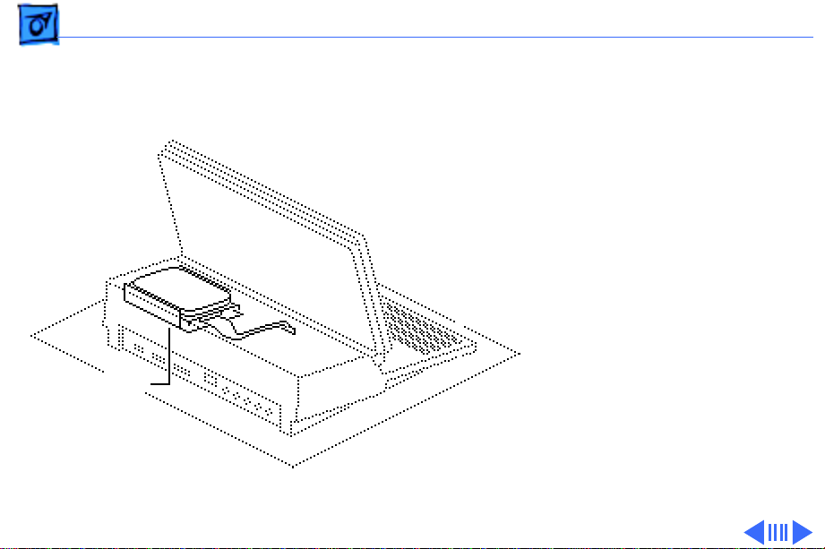
Take Apart Hard Drive - 12
Hard Drive
Before you begin, remove
the following:
• Rear cover
• Main battery
• Keyboard cover
• All option cards
Hard Drive
Caution:
precautions in Bulletins/
Safety.
Review the ESD
Page 51

Take Apart Hard Drive - 13
Caution:
replace the battery cover
after removing the main
battery. Failure to put the
cover on leaves power
connected to the logic board.
Removing and replacing
modules with power
available could damage any
module.
Remember to
Page 52

Take Apart Hard Drive - 14
1 Disconnect the following
cable connectors from
the logic board:
• Display cable from
J19
• Hard drive cable from
J18
Hard
Drive
Page 53

Take Apart Hard Drive - 15
2 Close the display and
move the hard drive
cable toward the rear of
the computer.
3
Caution:
Do not loosen
or remove the Torx
screws that attach the
hard drive to the drive
shield. Doing so could
Plastic Latch
irreparably damage the
hard drive.
Hard
Drive
Plastic Latch
Hard Drive
Cable
Unsnap the two plastic
latches and remove the
hard drive (with
shield) from the
subframe.
Page 54

Take Apart Hard Drive - 16
Replacement Note:
information on removing the
hard drive form the carrier
and returning drives,
cables, and carriers to
Apple, refer to Additional
Procedures in the Hard
Drives Manual.
For
Page 55

Take Apart Upper Floppy Drive - 17
Upper Floppy Drive
Before you begin, remove
the following:
• Rear cover
• Main battery
• All option cards
Upper Floppy Drive
Caution:
precautions in Bulletins/
Safety.
Review the ESD
Page 56

Take Apart Upper Floppy Drive - 18
Caution:
replace the battery cover
after removing the main
battery. Failure to
reinstall the cover leaves
power connected to the logic
board. Removing and
replacing modules with
power available could
damage any modules.
Remember to
Page 57

Take Apart Upper Floppy Drive - 19
1 Disconnect the floppy
drive cable from the
floppy drive.
2 Unsnap the two plastic
latches and remove the
floppy drive (with
retainer) from the
subframe.
3 Depress the two metal
Plastic Latch
tabs and remove the
floppy drive mechanism
Upper
Floppy
Drive
Floppy Drive
Cable
Plastic Latch
from the retainer.
Page 58

Take Apart Upper Floppy Drive - 20
Replacement Note:
you install a replacement
1.4 MB SuperDrive, you
must remove the dust shield.
Before
Page 59

Take Apart Lower Floppy Drive - 21
Lower Floppy Drive
Before you begin, remove
the following:
• Rear cover
• Main battery
• All option cards
• Upper floppy drive (if
installed)
• Hard drive (if installed)
Lower Floppy
Drive
Caution:
precautions in Bulletins/
Safety.
Review the ESD
Page 60

Take Apart Lower Floppy Drive - 22
Caution:
replace the battery cover
after removing the main
battery. Failure to
reinstall the cover leaves
power connected to the logic
board. Removing and
replacing modules with
power available could
damage any modules.
Remember to
Page 61

Take Apart Lower Floppy Drive - 23
1 Disconnect the floppy
drive cable from the
floppy drive.
2 Remove the floppy drive
from the subframe.
Lower
Floppy
Drive
Floppy Drive
Cable
Replacement Note:
Before
you install a replacement
1.4 MB SuperDrive, you
must remove the dust shield.
Page 62

Take Apart Keyboard Components - 24
Keyboard Components
Before you begin, remove
the following:
• Rear cover
Trackball/Keypad
Keyboard
• Main battery
• Keyboard cover
Caution:
precautions in Bulletins/
Safety.
Review the ESD
Page 63

Take Apart Keyboard Components - 25
Caution:
replace the battery cover
after removing the main
battery. Failure to
reinstall the cover leaves
power connected to the logic
board. Removing and
replacing modules with
power available could
damage any modules.
Remember to
Page 64

Take Apart Keyboard Components - 26
Note:
The take apart
procedure is the same for
Input Device Cable
the keyboard, trackball, and
numeric keypad.
1 Disconnect the flat cable
from the device you want
to remove.
• Keyboard
• Trackball
• Numeric keypad
Page 65

Take Apart Keyboard Components - 27
2 Starting at one side of
the device, pull or pry
up the frame of the
device while releasing
each plastic retainer
clip.
3 After you release all the
clips, lift the back end of
the device up and out of
the computer.
Page 66

Take Apart Speaker - 28
Speaker
Before you begin, remove
the following:
• Rear cover
• Main battery
• Keyboard cover
Speaker
Caution:
precautions in Bulletins/
Safety.
Review the ESD
Page 67

Take Apart Speaker - 29
Caution:
replace the battery cover
after removing the main
battery. Failure to
reinstall the cover leaves
power connected to the logic
board. Removing and
replacing modules with
power available could
damage any modules.
Remember to
Page 68

Take Apart Speaker - 30
1 Disconnect the speaker
Speaker
cable from connector
J16 on the logic board.
2 Push out the two latches
and remove the speaker
from the subframe.
Page 69

Take Apart Display Assembly - 31
Display Assembly
Before you begin, remove
Display Assembly
the following:
• Rear cover
• Main battery
• Keyboard cover
Caution:
precautions in Bulletins/
Safety.
Review the ESD
Page 70

Take Apart Display Assembly - 32
Caution:
replace the battery cover
after removing the main
battery. Failure to
reinstall the cover leaves
power connected to the logic
board. Removing and
replacing modules with
power available could
damage any modules.
Remember to
Page 71

Take Apart Display Assembly - 33
1 Disconnect the display
cable from connector
J19 on the logic board.
Display Cable
Page 72

Take Apart Display Assembly - 34
2 Twist the left clutch
cover back and forth and
Left Clutch
Retainer
pull it away from the
display.
3 Lift and remove the left
clutch retainer.
Left Clutch
Cover
Page 73

Take Apart Display Assembly - 35
4 Pull the display with
your right hand while
maintaining slight
outward pressure on the
computer with your left
Left Clutch
Mechanism
hand. This movement
pulls off the left clutch
mechanism (1).
5 Disengage and remove
the display assembly
from the right clutch
mechanism (2).
Page 74

Take Apart LCD Display (Nonbacklit) - 36
LCD Display (Nonbacklit)
Before you begin, remove
the following:
LCD Display
(nonbacklit)
• Rear cover
• Main battery
• Keyboard cover
• Display assembly
Page 75

Take Apart LCD Display (Nonbacklit) - 37
Caution:
extremely susceptible to
ESD damage. Review the ESD
precautions in Bulletins/
Safety. Handle the display
by the edges and do not touch
the component side or
remove the tape.
The LCD display is
Page 76

Take Apart LCD Display (Nonbacklit) - 38
Caution:
replace the battery cover
after removing the main
battery. Failure to
reinstall the cover leaves
power connected to the logic
board. Removing and
replacing modules with
power available could
damage any modules.
Remember to
Page 77

Take Apart LCD Display (Nonbacklit) - 39
Mounting Screw Mounting Screw
Display Bezel
Carrying Handle
Center Pivot Cover
1 Slide the carrying handle
from the display to its
fully extended position.
Note:
Later model Portables
and replacement displays
have two Phillips screws
securing the bezel to the
housing.
2 Remove the two bezel
mounting screws, if
present.
Page 78

Take Apart LCD Display (Nonbacklit) - 40
3 Turn the opening of the
center pivot cover
toward the display. Pull
the cover from the
display housing.
Center Pivot Cover
Page 79

Take Apart LCD Display (Nonbacklit) - 41
4 Insert a jeweler’s
screwdriver into the
display latch opening on
the right side of the
display housing. Push
the screwdriver into the
opening until you hear a
click.
5 Pull the display bezel
toward you with your
fingers while you push
the display housing with
Display Latch Opening
your thumb. The two
parts separate about 1/8
inch.
6 Repeat for the left side.
Page 80

Take Apart LCD Display (Nonbacklit) - 42
Display Bezel
7 Lift the display bezel and
the carrying handle off
the display housing.
Carrying Handle
Page 81

Take Apart LCD Display (Nonbacklit) - 43
8 Disconnect the display
cable.
9 Pull out the two display
mounting clips with
your thumbs and lift the
Display
Mounting
Clip
Display
Cable
Display Assembly
Display
Mounting
Clip
display with your index
fingers.
10 Slide the display up and
out of the housing.
Page 82

Take Apart LCD Display (Backlit) - 44
LCD Display (Backlit)
Before you begin, remove
the following:
LCD Display
(backlit)
• Rear cover
• Main battery
• Keyboard cover
• Display assembly
Page 83

Take Apart LCD Display (Backlit) - 45
Caution:
extremely susceptible to
ESD damage. Review the ESD
precautions in Bulletins/
Safety. Handle the display by
the edges and do not touch the
component side or remove
the tape.
The LCD display is
Page 84

Take Apart LCD Display (Backlit) - 46
Caution: Remember to
replace the battery cover
after removing the main
battery. Failure to
reinstall the cover leaves
power connected to the logic
board. Removing and
replacing modules with
power available could
damage any modules.
Page 85

Take Apart LCD Display (Backlit) - 47
Carrying Handle
Mounting Screw
Display Bezel Center Pivot Cover
Mounting Screw
1 Slide the carrying handle
from the display to its
fully extended position.
Note: Later model Portables
and replacement displays
have two Phillips screws
securing the bezel to the
housing.
2 Remove the two bezel
mounting screws, if
present.
Page 86

Take Apart LCD Display (Backlit) - 48
3 Turn the opening of the
center pivot cover
toward the display. Pull
the cover from the
display housing.
Center Pivot Cover
Page 87

Take Apart LCD Display (Backlit) - 49
4 Insert a jeweler’s
screwdriver into the
display latch opening on
the right side of the
display housing. Push
the screwdriver into the
opening until you hear a
click.
5 Pull the display bezel
toward you with your
fingers while you push
the display housing with
Display Latch Opening
your thumb. The two
parts separate about 1/8
inch.
6 Repeat for the left side.
Page 88

Take Apart LCD Display (Backlit) - 50
Display Bezel
7 Lift the display bezel and
the carrying handle off
the display housing.
Carrying Handle
Page 89

Take Apart LCD Display (Backlit) - 51
8 Press the tab and
disconnect the CCFL-toinverter cable.
Inverter Board-to-LCD
Display Cable
Inverter Board
CCFL-to-Inverter
Cable
9 Slide out the release
latch and remove the
cable that connects the
inverter board to the
LCD display.
10 Note: Skip this step if
you are replacing only
the display.
Using a jeweler’s
screwdriver, gently pry
the inverter board from
the display housing.
Page 90

Take Apart LCD Display (Backlit) - 52
11 Pull out the two display
mounting clips with
your thumbs and lift the
display with your index
fingers.
12 Slide the display up and
out of the housing.
Display
Mounting
Clip
Display Assembly
Display
Mounting
Clip
Page 91

Take Apart LCD Display (Backlit) - 53
13 Turn over the display
assembly.
14 Slide out the release
latch and remove the
display cable from the
connector.
Connector
Display Assembly
(Upside Down)
Latch
Display Cable
Page 92

Take Apart Logic Board - 54
Logic Board
Before you begin, remove
the following:
• Rear cover
• Main battery
• Keyboard cover
• Display assembly
• Keyboard
• Trackball/numeric
keypad
• All option cards
Caution: Review the ESD
Logic Board
precautions in Bulletins/
Safety.
Page 93

Take Apart Logic Board - 55
Caution: Remember to
replace the battery cover
after removing the main
battery. Failure to
reinstall the cover leaves
power connected to the logic
board. Removing and
replacing modules with
power available could
damage any modules.
Page 94

Take Apart Logic Board - 56
1 Disconnect the following
Outline of Logic Board
cable connectors from
the logic board:
• Input device cable
from J13
• Input device cable
from J20
• Battery cable from
J17
• Hard drive cable from
J18
• Lower floppy drive
cable from J14
• Upper floppy drive
cable from J15
• Speaker cable from
J16
Page 95

Take Apart Logic Board - 57
Caution: Do not lift the
subframe too far. Lifting too
far puts excess strain on the
subframe and logic board and
could damage both.
2 Using a flat-blade
screwdriver, pull the
latch from the subframe.
When the latch is clear,
lift the left side of the
Left Subframe Latch
frame.
Page 96

Take Apart Logic Board - 58
Right
Subframe
Latch
3 Hold the left side of the
subframe up—far enough
to keep it from being
held by the clip—and
press in the clip at the
right front of the
subframe. Lift the
subframe a little
further.
4 Using a flat-blade
screwdriver, release the
plastic latch at the right
side of the subframe.
Page 97

Take Apart Logic Board - 59
Subframe
(Upside Down)
5 To remove the subframe
from the bottom case,
lift the front of the
subframe and pull it
toward you.
6 Place the subframe
upside down.
Page 98

Take Apart Logic Board - 60
7 Release each of the
plastic clips that secure
the logic board to the
subframe. Release the
clips in the order shown.
Logic Board
As you release each clip,
gently lift the logic
board and proceed to the
next clip.
8 Remove the logic board
from the subframe.
Typical Securing Clip
Page 99

K
Service Source
Upgrades
Macintosh Portable
Page 100
Upgrades Hard Drive Installation - 1
Hard Drive Installation
Before you begin, do the
following:
• Disconnect the power
adapter
• Remove the rear cover
• Remove the main battery
• Remove the keyboard
cover
• Remove any option cards
Hard Drive
Caution:
precautions in Bulletins/
Safety.
Review the ESD
 Loading...