

Page 1

K
Service Source
Network Server 500 and
700 Series
Network Server 500/132, Network Server 700/150,
and Network Server 700/200
Page 2
K
Service Source
Basics
Network Server 500 and
700 Series
Page 3
Basics Overview - 1
Overview
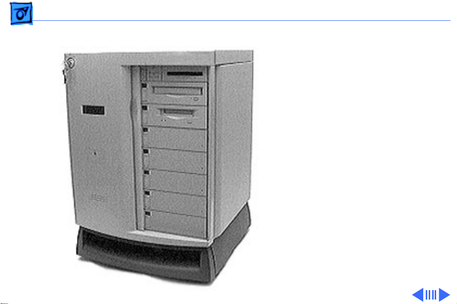
The Network Server 500
Series and Network Server
700 Series are a family of
high-performance servers
based on the PowerPC 604
or 604e Reduced Instruction
Set Computer (RISC)
microprocessor. Designed
around an innovative
architecture, the servers
provide high performance
and scalability for medium
to large workgroups running
AIX-based applications.
Page 4

Basics Overview - 2
Network Server 500 Series Features
Features of the Network Server 500 Series include the
following:
• 132-MHz PowerPC 604 microprocessor
• 32K on-chip cache
• 512K Level 2 cache
• 32 MB main DRAM memory, expandable to 512 MB
• Six PCI expansion slots
• Seven drive bays for internal, redundant drives that are
hot-swappable with RAID
• Total disk capacity with RAID: 368 GB
• Built-in Ethernet interface using the Apple Ethernet
Cable System (AAUI)
• One SCSI-1 channel with external port
• Two Fast/Wide SCSI-2 channels for internal devices
Page 5

Basics Overview - 3
• Built-in 1024 x 768, 800 x 600, 640 x 480 video
support for 14-inch, 15-inch, 17-inch, and 20-inch
multi-sync monitors
• CD, floppy bays (DAT is optional)
• An LCD display that monitors server activity and can be
used for diagnostic tests
Network Server 700 Series Features
Features of the Network Server 700 Series include the
following:
• 150-MHz PowerPC 604 microprocessor (Network
Server 700/150) or 200-MHz PowerPC 604e
microprocessor (Network Server 700/200) or two
200-MHz PowerPC 604e microprocessors (Network
Server 700/200SMP)
• 32K on-chip cache (Network Server 700/150) or 64K
on-chip cache (Network Server 700/200)
Page 6

Basics Overview - 4
• 1 MB Level 2 cache
• 48 MB main DRAM memory, expandable to 512 MB
• Six PCI expansion slots
• Seven drive bays in the front for internal, redundant
drives that are hot-swappable with RAID
• Two drive bays in the rear for internal fixed drives
• Total disk capacity with RAID: 368 GB
• Built-in Ethernet interface using the Apple Ethernet
Cable System (AAUI)
• One SCSI-1 channel with external port
• Two Fast/Wide SCSI-2 channels for internal devices
• Redundant, hot-swappable power supplies
• Built-in 1024 x 768, 800 x 600, 640 x 480 video
support for 14-inch, 15-inch, 17-inch, and 20-inch
multi-sync monitors
• CD, floppy bays (DAT or 8 mm tape drive is optional)
• An LCD display that monitors server activity and can be
used for diagnostic tests
Page 7

Basics Configurations - 5
Configurations
At product introduction, the following was the standard
configuration for the Network Server 500/132:
• 132-MHz PowerPC 604 processor card
• 512 KB Level 2 cache
• 32 MB parity DRAM minimum
• 2 GB Fast/Wide hard drive
• DAT2 tape drive
• AppleCD 600i CD-ROM drive
• Floppy disk drive
• AppleTalk administration utilities
• 325 watt power supply
At product introduction, the standard configuration for the
Network Server 700/150 was
• 150-MHz PowerPC 604 processor card
• 1 MB Level 2 cache
Page 8

Basics Configurations - 6
• 48 MB parity DRAM minimum
• 4 GB Fast/Wide hard drive
• DAT2 tape drive
• AppleCD 600i CD-ROM drive
• Floppy disk drive
• AppleTalk administration utilities
• 425 watt power supply
At product introduction, the standard configuration for the
Network Server 700/200 was
• 200-MHz PowerPC 604e processor card
• 1 MB Level 2 cache
• 48 MB parity DRAM minimum
• Two 4 GB Fast/Wide hard drives
• AppleCD 1200i CD-ROM drive
• Floppy disk drive
• AppleTalk administration utilities
• 425 watt power supply
Page 9

Basics Configurations - 7
Note:
AIX software does not come preinstalled in standard
configurations of the Network Server 500 and 700 Series.
The AIX software must be purchased separately.
Page 10

Basics Options and Upgrades - 8
Options and Upgrades
Apple offers the following options and upgrades to enhance
the operation and performance of the Network Server 500
and 700 Series.
• Processor Upgrade
Card with One 200-MHz 604e PowerPC Processor
M5177Z/A
• Main Memory
16 MB Parity Memory Kit M4017Z/A
32 MB Parity Memory Kit M4018Z/A
64 MB Parity Memory Kit M4019Z/A
Page 11

Basics Options and Upgrades - 9
• Hard Drives
2 GB Fast/Wide SCSI Hard Drive w/ Tray M4022Z/A
4 GB Fast/Wide SCSI Hard Drive w/ Tray M4023Z/A
9 GB Fast/Wide SCSI Hard Drive w/ Tray M5178Z/A
• Rear Hard Drives and Bracket
2 GB Fast/Wide SCSI Hard Drive & Bracket M4818Z/A
Two 4 GB Fast/Wide SCSI Hard Drives & Bracket
M4819Z/A
• CD-ROM and Tape Drives
4-X CD-ROM Drive w/ Tray M4024Z/A
DAT-2 SCSI Tape Drive w/ Tray M4025Z/A
8 mm Tape Drive (20/40 GB) w/ Tray M4026Z/A
Page 12

Basics Options and Upgrades - 10
• Storage Bay Accessories
SCSI Drive Adapter Kit (68 and 50-Pin) M4028Z/A
SCSI Front Drive Bezel Kit M4029Z/A
• Redundant Power Supply (NS 700 Series Only)
425 W Hot-swappable Power Supply M4035Z/A
• PCI Expansion Cards
PCI RAID Disk Array Card M4030Z/A
RAID External SCSI Cable (68-Pin to 68-Pin)
M4031Z/A
PCI Fast Ethernet Card (100Base-TX) M3906Z/A
PCI Ethernet Card (10Base2/10Base-T/AAUI)
M4709Z/A
• 19-inch Rack Mount Accessory Kit M4036Z/A
Page 13

Basics Options and Upgrades - 11
• AIX Accessory Kit
AIX Accessory Kit, Version 4.1.4 M4525Z/A
AIX Accessory Kit, Version 4.1.4.1 M4525Z/B
AIX Accessory Kit, Version 4.1.5 M4525Z/C
AIX Update Kit, Version 4.1.4 to Version 4.1.4.1
M5494Z/A
AIX Upgrade Kit, Unlimited User M4891Z/A
Note:
Third-party manufacturers also offer a wide variety
of products that can be installed to enhance the server.
Page 14

Basics Service Strategy - 12
Service Strategy
Service the Network Server 500 and 700 Series through
module exchange and parts replacement. Customers can
request on-site service from an Apple Authorized Service
Provider Plus (AASP+) or carry-in service from an AASP,
or they can choose service from the Apple Assurance
program.
Ordering
Apple service providers planning to support the Network
Server 500 and 700 Series may purchase Service modules
and parts to develop servicing capability. To order parts,
use the AppleOrder system or refer to the “Service Price
Pages.”
Large businesses, universities, and K-12 accounts must
Page 15

Basics Service Strategy - 13
provide a purchase order on all transactions, including
orders placed through the AppleOrder system. Service
providers not enrolled in AppleOrder may fax their orders
to Service Provider Support (512-908-8125) or mail
them to
Apple Computer, Inc.
Service Provider Support
MS 212-SPS
Austin, TX 78714-9125
If you have further questions, please call Service Provider
Support at 800-919-2775 and select option #1.
Page 16

Basics Service Strategy - 14
Warranty and AppleCare
Both the Network Server 500 Series and Network Server
700 Series are covered under the Apple One-Year Limited
Warranty. The AppleCare Service Plan is also available for
these systems. For part number and pricing information,
refer to the AppleCare CPU “Service Price Pages.” Service
providers are reimbursed for warranty and AppleCare
repairs made to these systems.
Diagnostics
Use the Network Server Diagnostic Utility on the Service
Source companion disc (or on its own floppy disk) to test the
new servers. Refer to the Troubleshooting chapter for more
information on the Network Server Diagnostic Utility.
Page 17

Basics Safety Issues - 15
Safety Issues
See Bulletins/Safety for general safety information.
Skills and Tools
Knowledge of the AIX operating system and RAID technology
is helpful. Familiarity with the Network Server Diagnostics
Utility is a plus.
No additional tools are required for the Network Server 500
and 700 Series above and beyond what the service technician
already has.
Page 18

Basics Compatibility Issues - 16
Compatibility Issues
The following are compatibility issues associated with
upgrading memory or installing PCI expansion cards for
video, graphics applications, and networking and
communications:
• The Network Server uses 72-bit-wide, 168-pin parity
DRAM Dual Inline Memory Modules (DIMMs), which
should be installed in matched pairs (for example, two 8
MB DIMMs). Your server’s DIMMs are fast-paged mode,
parity DRAM, with an access time of 60-nanoseconds or
faster. Nonparity DIMMs with 70-nanosecond or faster
access time DRAM will work; however, if there is any
nonparity DRAM installed, all server parity checking is
disabled.
Page 19

Basics Compatibility Issues - 17
• Some DIMMs and all Single Inline Memory Modules
(SIMMs) from older Macintosh computers are not
compatible. For more detailed information, see
“Appendix B: DRAM Configurations” of “Setting up the
Network Server.”
• The Network Server uses cards designed according to the
Peripheral Component Interconnect (PCI) standard.
Your server cannot accommodate NuBus cards, which
were designed for older Macintosh computers.
• The combined power consumption of PCI expansion cards
must not exceed the limits specified for the Network
Server 500 and 700 Series.
• The Network Servers support only multisynchronous
displays.
• The 8 mm tape drive can read from but not write to
standard metal particle tapes. The tape heads must be
cleaned after reading from a standard metal particle tape
before an AME tape can be used.
Page 20

Basics Setup and Operation - 18
Setup and Operation
Refer to “Chapter 5: Starting Up Your Server” of “Setting
up the Network Server” and “Chapter 3: System Startup,
Logging In, Shutting Down, and Rebooting” of “Using AIX,
AppleTalk Services and Macintosh OS Utilities on the
Network Server” for information on how to
• Install AIX on the server
• Start up, log in, shut down, and restart the server
• Use AIX Windows and the Common Desktop Environment
• Use InfoExplorer
• Use system administration tools
• Set up AppleTalk and AppleTalk Services
• Use Disk Management Utility
• Access the server remotely with CommandShell
Note:
You can find these manuals on the Service Source
Companion CD.
Page 21

Basics Setup and Operation - 19
Turning the Server On
To turn on the server you must perform the following steps:
• Turn on the monitor.
• Turn on all the external devices.
• Turn the key in the rear drawer lock to the locked
position.
• Turn the front lock key to the unlocked or locked position.
• Turn the server on by pressing the Power On button
(next to the floppy drive).
The server will run the power-on self test and then clear
the LCD display and display the ROM version and power
supply status. During the startup process, messages will
appear on the third line of the LCD display. Under normal
circumstances, these messages will clear quickly, but if
there is a startup problem, one of the messages may be
displayed continuously.
Page 22
Basics Setup and Operation - 20
Shutting Down the Server
Note: You must have root privileges to shut down the server.
To shut down the server always use the Shutdown command
as it is the safest and most thorough way to halt the server.
Log in to the server as root and enter
You can notify the users that the system is about to stop
operations, terminate all existing processes, and unmount
all filesystems by using the appropriate options provided in
the Shutdown command. By default, the system waits one
minute before stopping the user processes and the init
process.
shutdown -F
Page 23

Basics Setup and Operation - 21
Restarting the Server
You must have root privileges to restart the server. Use the
command
the system is running and other users are logged in.
shutdown -r
instead of the Reboot command when
Page 24

Basics Front View - 22
Front View
The following figure illustrates the front view of the
Network Server 500 and 700 Series. Note that the monitor
and keyboard must be purchased separately.
Page 25
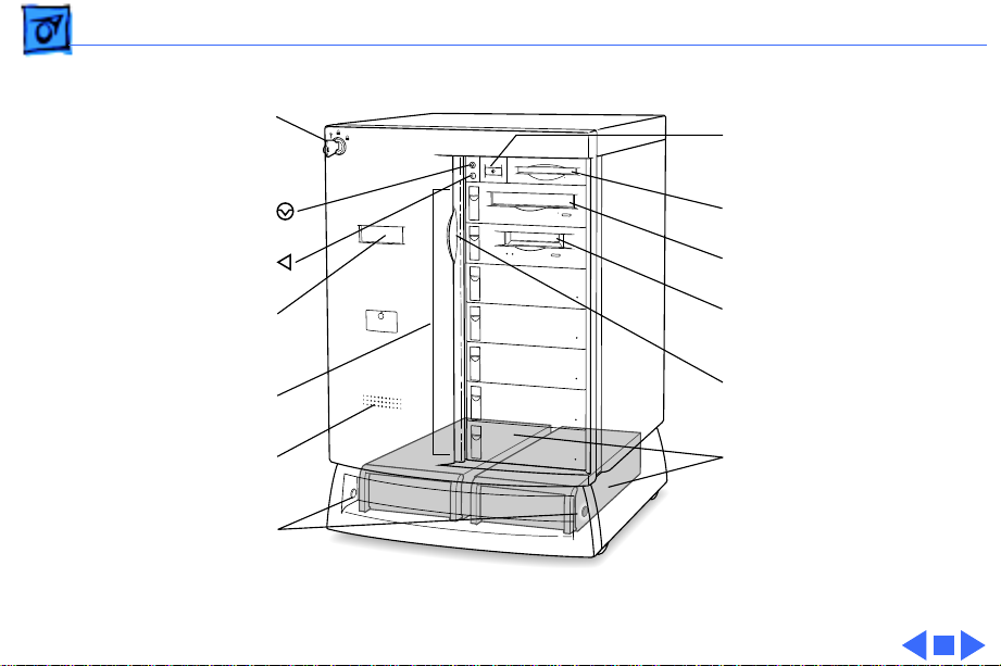
Basics Front View - 23
Front key switch
locks sliding security
door and base cover
Power button
Interrupt button
Reset button
LCD displays system
diagnostics and
status messages
Front internal
drive bays
Speaker
Release buttons to
remove base cover
Figure: Network Server 500 and 700 Series Front View
Floppy disk drive
CD-ROM drive
Optional tape
drive
Sliding security
door
Power supplies
NS500 Series includes a
single power supply
NS700 Series offers an
optional second
power supply
Page 26

Basics Back View - 24
Back View
The Network Server 500 Series and Network Server 700
Series offer the following external ports: SCSI, AAUI
Ethernet, serial printer, serial modem, Apple Desktop Bus
(ADB), sound input, and sound output.
The figures on the next pages illustrate the rear panel of the
Network Server 500 and 700 Series.
Page 27
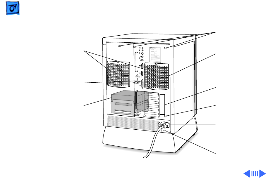
Basics Back View - 25
Thumbscrews
Replaceable, hot-
swappable fans
Rear drawer lock
Optional rear bracket-
mounted drives
(NS700 Series only)
Figure: Network Server 500 and 700 Series Back View
Hot-swappable
fans
PCI card
connection ports
Thumbscrews
Power cord
protector
Security lock
Page 28
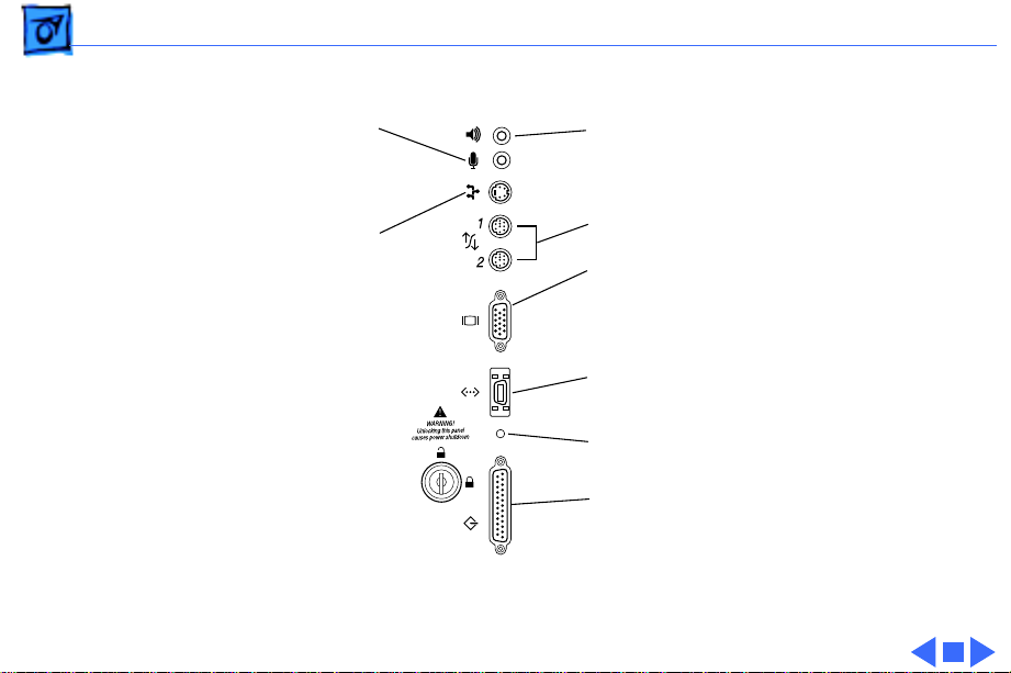
Basics Back View - 26
Sound input port
ADB port
Sound output port
Serial connection ports
Monitor port
VGA HD-IS video
connects your monitor to
your server
Ethernet port
Status light
SCSI port
Figure: Network Server 500 and 700 Series Ports
Page 29

Basics Logic Board - 27
Logic Board
The following figure illustrates the connectors, battery
holder, cache and DRAM DIMM sockets, PCI slots, processor
card slot, Cuda reset button, and the power on/off button on
the Network Server 500 and 700 Series logic board.
Page 30
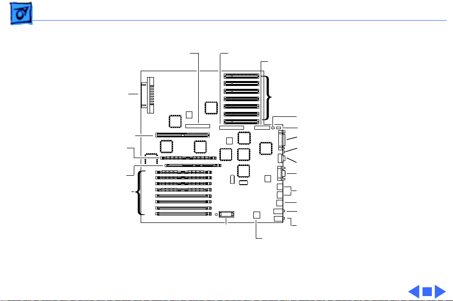
Basics Logic Board - 28
SCSI
Battery
Battery
Holder
Holder
SCSI
Bus 0
Bus 0
Control Bus
Control Bus
PCI Slots
PCI Slots
Key
Key
Fan
Fan
External SCSI-1
External SCSI-1
Power on & Activity LED
Power on & Activity LED
AAUI Ethernet
AAUI Ethernet
Video
Video
Serial Ports
Serial Ports
ADB
ADB
Microphone
Microphone
Audio Output
Audio Output
Cuda Reset Button
Cuda Reset Button
Power Supply
Power Supply
Processor Card Slot
Processor Card Slot
ROM SIMM
ROM SIMM
Cache DIMM
Cache DIMM
DRAM DIMM Slots
DRAM DIMM Slots
Figure: Network Server 500 and 700 Series Logic Board Connectors
SCSI
SCSI
Bus 1
Bus 1
Page 31

Basics Overview of Core Technologies - 29
Overview of Core Technologies
This section provides information on core technologies built
into the Network Server 500 and 700 Series.
PowerPC 604 and 604e Microprocessor
The Network Server 500 Series and Network Server 700
Series are powered by a PowerPC 604 or 604e
microprocessor. An implementation of the PowerPC family
of RISC microprocessors, the PowerPC 604 or 604e uses
RISC technology to deliver high performance at the lowest
possible cost. Features include the following:
• Full RISC processing architecture
• 64-bit external data bus and a 32-bit address bus
Page 32

Basics Overview of Core Technologies - 30
• Five execution units that can operate in parallel (one
load-store unit, three integer units, and one three-stage
floating-point unit)
• Separate built-in caches for data and instructions, 16K
each for the 604 and 32K each for the 604e
• Advanced branching techniques for improved throughput
• Advanced 3.3-volt CMOS process technology (fully
compatible with TTL)
• Bus multiplier up to 3:1 for the 604 and up to 5:1 for
the 604e
The PowerPC 604 and 604e microprocessor is installed by
way of a processor card that plugs into the logic board,
allowing for maximum flexibility for future upgrades. The
Network Server 500 Series uses the 132-MHz version of
the PowerPC 604 microprocessor and the Network Server
700 Series uses the 150 MHz or 200 MHz version.
Page 33

Basics Overview of Core Technologies - 31
Memory Configurations
The Network Server 500 Series and Network Server 700
Series provide parity memory protection by using DRAM
Dual Inline Memory Modules (DIMMs) with parity instead
of DRAM Single Inline Memory Modules (SIMMs).
The server logic board has eight DRAM DIMM slots (each
with a 64-bit wide data bus) that allow a maximum of 512
MB of main memory.
Although single DIMMs may be added, to take advantage of
memory interleaving, the DIMMs should be installed in
matched pairs (for example, two 16 MB DIMMs).
Memory interleaving allows the computer to read or write
to its memory while other memory reads or writes are
occurring, thus providing maximum performance.
Page 34

Basics Overview of Core Technologies - 32
Important:
pin fast-paged mode, 60-nanosecond (ns) RAM access time
or faster. DRAM must support byte writes. SIMMs and some
DIMMs from older Macintosh computers will not work in the
Network Server. The parity DIMMS should be installed in
matched pairs (for example, two 16 MB DIMMs, one in slot
1A, the other in slot 1B). Nonparity DRAM with 70nanosecond DRAM access time or faster will work, however
if there is any nonparity DRAM installed, all server parity
checking is disabled.
Important:
are NOT compatible with the Network Server 500 and 700
Series.
The parity DIMMs should be 72-bit-wide 168-
The SIMMs used in previous Macintosh models
Page 35

Basics Overview of Core Technologies - 33
1A
1B
DRAM
DIMM Slots
Figure: Network Server 500 and 700 Series Memory Locations
2A
2B
3A
3B
4A
4B
Page 36

Basics Overview of Core Technologies - 34
Ethernet Support
The Network Server 500 Series and Network Server 700
Series come with a built-in Ethernet port (AAUI) for
connecting to a high-speed Ethernet network. The AAUI
connector supports the Apple Ethernet Network Cable
System (which supports thicknet, thinnet, or 10BaseT
cable systems). To connect the server to an Ethernet
network, you must have one of the following Ethernet Media
adapters (depending on the type of network cabling used):
• Apple Ethernet Thin Coax Transceiver
• Apple Ethernet Twisted-Pair Transceiver
• Apple Ethernet AUI Adapter
With the appropriate communications card and software, the
server also can be connected to other network types.
Page 37

Basics Overview of Core Technologies - 35
Peripheral Component Interconnect (PCI)
PCI (Peripheral Component Interconnect) is a highperformance architectural standard designed to eliminate
bottlenecks between a computer’s processor and its high
bandwidth peripherals (such as video graphics and network
components). The PCI Local Bus is a high-performance, 32bit or 64-bit bus with multiplexed address and data lines. It
is intended for use as an interconnect mechanism between
highly integrated peripheral controller components,
peripheral add-in boards, and the processor/memory
systems.
The Network Server 500 Series and Network Server 700
Series provide six 64-bit, universal (5 volt + 3.3 volt)
PCI expansion slots that are compliant with PCI 2.0
specifications.
Page 38

Basics Overview of Core Technologies - 36
The expansion slots can be used to install cards for video and
graphics applications and for networking and
communications purposes.
The Cuda Chip
The Cuda is a microcontroller chip. Its function is to
• Turn on and off system power
• Manage system resets from various commands
• Maintain PRAM
• Manage the ADB
• Manage the real-time clock
Many system problems can be resolved by resetting the Cuda
chip (see the Troubleshooting chapter for examples). Press
the Cuda reset button on the logic board to reset the Cuda
chip. (See the Logic Board Diagram earlier in this chapter to
locate the Cuda reset button.)
Page 39

Basics Overview of Core Technologies - 37
If you continue to experience system problems after
resetting the Cuda chip, refer to the following section
“Resetting the Logic Board.”
Resetting the Logic Board
Resetting the logic board can resolve many system problems
(refer to the Troubleshooting chapter in this manual for
examples).
Whenever you have a unit that fails to power up, you should
follow this procedure before replacing any modules:
1 Unplug the computer.
2 Slide the rear drawer out. (Refer to the Take Apart
chapter for more instructions.)
Page 40

Basics Overview of Core Technologies - 38
3 Using a small, flat-blade screwdriver, pry open the
latch at the end of the battery holder, and lift off the
battery holder cover.
4 Remove the battery from its holder.
5 Make sure that the unit is not connected to any external
devices such as SCSI or serial port devices.
6 Wait at least 10 minutes before replacing the battery.
Be sure the battery is installed in the correct positive/
negative (+/-) direction.
7 Reassemble the computer and test the unit.
Note:
This procedure resets the computer’s parameter RAM
(PRAM). Be sure to check the computer’s time/date and
other system parameter settings afterwards.
Page 41

Basics Overview of New Technologies - 39
Overview of New Technologies
This section discusses new technologies being introduced
with the Network Server 500 and 700 Series.
AIX
The Network Server 500 Series and Network Server 700
Series are designed to run IBM AIX. The Network Servers
are shipped with the following software:
• AIX version 4.1.4 or 4.1.4.1 operating system
• AppleTalk and AppleTalk administration utilities.
AppleTalk allows remotely connected Macintosh
computers to access the AIX server without using TCP/IP
or other networking protocols.
Page 42

Basics Overview of New Technologies - 40
• Two symbiotic applications, Discus and CommandShell,
created by Apple Computer, Inc., and engineered for use
with AIX on the Network Server 500 and 700 Series.
CommandShell is a terminal emulator that runs multiple
windows on a system, while Discus is a diskmanagement system that allows users to manage all
aspects of disk storage. Discus provides a graphical user
interface and offers various views of disk-storage
structure, as well as management commands.
Note:
Applications that use a Macintosh interface for
handling UNIX tasks are called “symbiotic applications.”
Page 43

Basics Overview of New Technologies - 41
SCSI IDs and Drive Termination
The Network Server 500 Series and Network Server 700
Series each include three separate SCSI buses: two internal
SCSI buses and one external bus. The buses accommodate
four, five, and seven SCSI devices, respectively. Thus, a
total of 16 SCSI devices can be connected to the server
without adding PCI cards. The internal buses handle the
built-in startup hard drive, CD-ROM drive, tape drive, and
up to four additional SCSI drives on the Network Server 500
Series and six on the Network Server 700 Series. The
external bus accommodates up to seven external SCSI devices
in a chain (such as hard drives, CD-ROM drives, scanners,
printers, and tape-backup drives).
Page 44

Basics Overview of New Technologies - 42
To make installing SCSI devices as straightforward as
possible, and to reduce the potential for SCSI bus problems,
the internal SCSI cable has built-in termination. Before
installing a SCSI device, make sure that SCSI termination is
disabled on the device. To disable the SCSI termination, refer
to the installation manual of that device.
Note: The Fast/Wide SCSI-2 channels support only internal
drives used in the Network Server 500 and 700 Series.
Note: The server automatically assigns SCSI ID numbers to
internal drives as shown in the diagram on the next page.
Page 45

Basics Overview of New Technologies - 43
0
Bus 0
Server automatically
assigns these
SCSI IDs
Bus 1
1
2
3
4
5
6
0
Bus 1
1
Rear internal bracketmounted hard drives.
Available on Network
Server 700 Series
only
Figure: Network Server 500 and 700 Series SCSI IDs
Page 46

Basics Overview of New Technologies - 44
Fast/Wide SCSI
Designed to be I/O intensive, the Network Server 500
Series and Network Server 700 Series achieve enhanced
data throughput by providing two Fast/Wide SCSI-2
channels that support internal devices. The internal SCSI
buses on the Network Servers support transfer rates up to
40 MB/sec.
Note: The Fast/Wide SCSI-2 channels support only internal
drives used in the Network Server 500 and 700 Series.
Page 47

Basics Overview of New Technologies - 45
Network Server PCI RAID Card
The Network Server 500 Series and Network Server 700
Series offer six PCI expansion slots each, but due to a
limitation in the PCI Redundant Array of Independent Disks
(RAID) implementation, only four Network Server PCI
RAID cards can be installed in a single Network Server 500
or 700 Series computer.
The first or a single PCI RAID card is designed to be
connected to the server’s two internal SCSI-2 buses. In that
case, the two SCSI-2 controller chips on the logic board are
disabled and all internal SCSI devices (for example, hard
drives, CD-ROM, DAT tapes, and so on) are controlled by the
controller on the PCI RAID card.
Any other RAID card(s) in the system will provide external
Fast/Wide SCSI-2 connectors for connection of external
SCSI disk arrays.
Page 48

Basics Overview of New Technologies - 46
Hot-Swappable Drives
The Network Server 500 and Network Server 700 contain a
flexible SCSI backplane that allows the physical hotswapping and hot-removal of SCSI wide and narrow devices.
This ability to gracefully handle the logical addition and
removal of drives is operating-system dependent. The
optional Network Server PCI RAID Card allows the AIX
operating system to be buffered from the logical
consequences of drive addition and removal when setup in a
RAID configuration. Hence, hot plug and removal is only
recommended for RAID configurations.
An optional PCI RAID card must be installed to ensure
Note:
that data will not be lost when drives are hot-swapped.
Page 49

Basics Overview of New Technologies - 47
Hot-Swappable, Redundant Power Supplies
The Network Server 700 Series has two bays for two power
supplies. Although the server is shipped with only one
power supply installed in the left bay, when a second power
supply is installed in the other bay (right), the server
power supplies become hot-swappable. When one of the
installed power supplies fails, its LED will turn off. The
failed power supply can then be replaced without shutting
down the server. (A message will display on the LCD
indicating that it is safe to shutdown the server.)
Hot-swappable, redundant power supplies are not
Note:
available for the Network Server 500 Series.
Page 50

Basics Overview of New Technologies - 48
Display and Diagnostics
On startup, the server executes the power-on self test, and
then displays the ROM version and copyright information on
the LCD. It then starts a series of tests, during which the
ROM version and the parity DRAM size remain on the
display.
During the test phase of the startup process, the server
displays startup progress messages on the LCD display.
Table 1 lists the progress messages along with the system
module(s) in use.
Page 51

Basics Overview of New Technologies - 49
Table 1: Progress Messages
LCD
Message
DRAM test #1 Begins 3 DIMMs, logic board
ROM SIMM Test Begins 3 ROM SIMM, logic
DRAM test #2 Begins 3 DIMMS, logic
LONG DRAM test Begins 3 DIMMS, logic
Line
System Module(s)
in Use
board, processor
card
board, processor
card
board, processor
card
Page 52

Basics Overview of New Technologies - 50
Table 1: Progress Messages (Continued)
LCD
Message
Turning on Caches 3 Cache DIMM,
Jumping to RAM Prog 3 DIMMS, logic board
Testing Parity DIMMs 3 DIMMs, logic board
MainLBU Enet Setup 3 Logic board
Sounding Boot Beep 3 Logic board
Sizing RAM DIMMs 3 DIMMs
ROM SIMM Data Access 3 ROM SIMM
Line
System Module(s)
in Use
processor card,
logic board
Page 53

Basics Overview of New Technologies - 51
Table 1: Progress Messages (Continued)
LCD
Message
Allocating RAM DIMMs 3 DIMMS, logic
MainLBUNVRAM Setup 3 Processor card,
CPU Card Info Setup 3 Processor card,
L2 Cache SIMM Setup 3 L2Cache SIMM,
Testing L2 Cache SIMM 3 L2Cache SIMM,
Line
System Module(s)
in Use
board, processor
card
logic board
logic board
processor card,
logic board
processor card,
logic board
Page 54

Basics Overview of New Technologies - 52
Table 1: Progress Messages (Continued)
LCD
Message
RAM/ROM/NVRAM:
PASSED
If the server stops (“freezes” or “hangs”) with one of the
progress messages displayed, the information indicated may
be used to identify the module(s) in use. The module(s)
might have failed, be incorrectly installed, or be
incompatible.
Line
3
System Module(s)
in Use
Page 55

Basics Overview of New Technologies - 53
After all the tests are complete, the LCD will display
something similar to this:
ROM ver.1.1.20.1
0048 MB Parity DRAM
150 MHz 604, 50 MHz Bus
1024 KB Level 2 Cache
If the server is unable to load the operating system from a
CD or hard drive, a problem may have been found during
startup. Problem messages displayed by the server are
listed in Table 2.
Note: The module(s) identified in the problem message
might have failed, be incorrectly installed, or be
incompatible.
Page 56

Basics Overview of New Technologies - 54
Table 2: Problem Messages
LCD
Message
L2 Cache SIMM Failed 1
ROM SIMM Failed 1
MainLBUNVRAM Failed 1 Located on logic
Line Module(s)
board.
RAM DIMM 1A failed at
Address xxxxxxxx
1 RAM DIMMS
identified as 1A-4A
and 1B-4B.
Addresses are in
hexadecimal.
Page 57

Basics Overview of New Technologies - 55
Table 2: Problem Messages (Continued)
LCD
Message
MainLBUVideo ID Bad 1 Video subsystem is
MainLBU825#1 Failed 1 SCSI controller #1
MainLBU825#2 Failed 1 SCSI controller #2
Drive Fan Failed! 1 Fan on right when
Line Module(s)
located on logic
board.
is located on logic
board.
is located on logic
board.
facing rear of server
unit.
Page 58

Basics Overview of New Technologies - 56
Table 2: Problem Messages (Continued)
LCD
Message
Processor Fan Failed 1 Fan on left when
Temperature Too Hot! 1 Internal cabinet is
Temperature Warning! 1 Internal cabinet
Left Power Fail! 1 Power supply on left
Line Module(s)
facing server unit.
unsafe. Shut down
system immediately.
temperature is
becoming unsafe.
when facing front of
server unit.
Page 59

Basics Overview of New Technologies - 57
Table 2: Problem Messages (Continued)
LCD
Message
Right Power Fail! 1 Power supply on
Left Power Hot! 1 Power supply on left
Right Power Hot! 1 Power supply on
CudaNotResponding!!! 1 Logic board.
Line Module(s)
right when facing
front of server unit
(Network Server
700 Series only).
when facing front of
server unit.
right when facing
front of server unit
(Network Server
700 Series only).
Page 60

Basics Overview of New Technologies - 58
Table 2: Problem Messages (Continued)
LCD
Message
ParityAddrAtAddrFail 1 Logic board.
During long memory test, the server provides additional
information by placing consecutive dashes on line 4 of the
LCD display. Should the system freeze during the long
memory test, use the dash count to identify the DIMM last
tested. Table 3 lists the dash count and the DIMM slot tested.
Line Module(s)
Page 61

Basics Overview of New Technologies - 59
Table 3: DIMM Slot Testing
Number of
Dashes
Displayed DIMM Slot
1 Main board logic unit DRAM
(reserved for future use)
2 Main board logic unit DRAM
(reserved for future use)
31A
41B
51A
61B
72A
Page 62

Basics Overview of New Technologies - 60
Table 3: DIMM Slot Testing (Continued)
Number of
Dashes
Displayed DIMM Slot
82B
92A
10 2B
11 3A
12 3B
13 3A
14 3B
15 4A
16 4B
Page 63

Basics Overview of New Technologies - 61
Table 3: DIMM Slot Testing (Continued)
Number of
Dashes
Displayed DIMM Slot
17 4A
18 4B
Page 64

Basics Configuring the SCSI ID Cable - 62
Configuring the SCSI ID Cable
When you install a drive in a
SCSI
Connector
on Hard Drive
SCSI Cable
Connector
to Hard Drive
drive carrier, the way you
connect the SCSI ID cable to
the drive depends on which
type of drive you’re
installing. This section
describes how to connect the
SCSI ID cable for the 2
gigabyte (GB) and 4 GB IBM
and Seagate hard drives,
which are provided by
Apple for the Network
Server 500 and 700
Series. If you install a
Quantum drive or other
drive with an active high
LED signal, you need to
rewire the SCSI cable as
described later in this
section.
The figure on this page
shows the location of the
SCSI ID cable.
Page 65

Basics Configuring the SCSI ID Cable - 63
Connecting IBM and
Seagate Drives (2, 4,
and 9 GB)
Configuring SCSI
ID Cable
Rotate connector
to change connector
configuration
End view of connector
Wire
Open Connector
IBM 2 GB model #DFHS-S2W,
IBM 4 GB model #DFHS-S4W,
Seagate 9 GB model #ST19171,
and Quantum or other drives
with active high LED signal
Seagate 2 GB model #ST32550W
drive and Seagate 4 GB model
#ST15150W drive
The IBM and Seagate drives
(2, 4, and 9 GB) use a Type
1 cable. This cable connects
to the drive board at the back
of the drive tray and to the
SCSI connector on the hard
drive. The Type 1 SCSI cable
includes a six-pin connector
and a four-pin connector.
Check which kind of drive
you have, then connect the
cable to the drive according
to the figure on this page.
Page 66

Basics Configuring the SCSI ID Cable - 64
Rewiring Quantum
Drives and Drives with
Active High LEDs
To install a Quantum drive
or other drive with an active
high LED, you must remove
6
6
5
4
3
2
1
5
4
3
2
1
the wire that connects to pin
3 on the drive tray
connector, then insert the
wire at pin 1. After you
rewire the SCSI ID cable,
connect the cable to the
drive.
Page 67

Basics SCSI ID Cable Connector Matrix - 65
SCSI ID Cable Connector Matrix
SCSI Drive Cables Connectors
Type 1
Type 2
Type 3
Type 4
Drives
2, 4, and 9 GB
Hard Drives
and
8mm Tape Drive
DAT Drive
CD-ROM Drives
1.2 GB Hard Drive
The SCSI ID Cable Matrix on
this page shows the different
kinds of SCSI ID connectors
used in the Network Server
500 and 700 Series. You
must use the correct
“type” cable with each
drive listed.
Page 68

Basics Keylock Positions - 66
Keylock Positions
Left Position:
Service
• Front Door
• Base Door
• Power Supply
• Top Shelf
• Bottom Shelf
Upright Position:
Unlocked
A c c e s s A v a i l a b l e :
• Front Door
• Base Door
• Rear Drawer
• Power Supply
• Front Bezel Assembly
• Top Shelf
• Bottom Shelf
Right Position:
Locked
• Drive Trays
( If the front door
is positioned
properly)
The figure on this page
shows the three different
keylock positions (service,
unlocked, and locked) used
in the Network Server 500
and 700 Series. It also
indicates the modules that
may be accessed from each
position.
Page 69

K
Service Source
Specifications
Network Server 500 and
700 Series
Page 70

Specifications Processor - 1
Processor
CPU
Network Server 500/ 132
Network Server 700/ 150
Network Server 700/ 200
PowerPC 604 RISC microprocessor running at 132 MHz
Built-in FPU
32 KB of on-chip cache
Requires AIX version 4.1.4 or higher
PowerPC 604 RISC microprocessor running at 150 MHz
Built-in FPU
32 KB of on-chip cache
Requires AIX version 4.1.4 or higher
PowerPC 604e RISC microprocessor running at 200 MHz
Built-in FPU
64 KB of on-chip cache
Requires AIX version 4.1.4.1 or higher recommended
Page 71

Specifications Memory - 2
Memory
DRAM
Network Server 500/ 132
Network Server 700 Series
ROM
Clock/Calendar
Uses 168-pin, 72-bit, 60 ns (parity) or 70ns (non-parity)
DRAM DIMMs
32 MB standard expandable to 512 MB
48 MB standard expandable to 512 MB
4 MB ROM
CMOS custom circuitry with long-life lithium battery
Page 72

Specifications Memory - 3
Memory
Cache
Network Server 500/ 132
Network Server 700 Series
512 KB of Level 2 cache
1 MB of Level 2 cache
Page 73

Specifications I/O Interfaces - 4
I/O Interfaces
SCSI
Network Server 500/ 132
Network Server 700 Series
Serial
ADB
Two Fast/Wide SCSI-2 channels (which support internal devices)
and one SCSI-1 channel (which supports external devices).
A total of 14 SCSI devices (seven internal and seven external) can
be connected to the server without adding additional PCI cards.
A total of 16 SCSI devices (nine internal and seven external) can
be connected to the server without adding additional PCI cards.
Two RS-232/RS-422 serial ports compatible with LocalTalk
and GeoPort cables; mini DIN-8 connectors
One Apple Desktop Bus port for a keyboard, mouse, or a three-
button mouse.
Page 74

Specifications I/O Interfaces - 5
I/O Interfaces
Ethernet
Video
PCI
Built-in Ethernet (AAUI port)
SuperVGA (SVGA) port requires an HDI-15 cable.
Six PCI expansion slots, compatible with all PCI 2.0
specifications-compliant cards (not NuBus-compatible)
Page 75

Specifications Sound and Video - 6
Sound and Video
Sound
Video
16-bit stereo sound input and output ports.
Built-in 1024 x 768, 800 x 600, 640 x 480 video support for
14-inch, 15-inch, 17-inch, and 20-inch monitors.
The following table shows the image size for monitors connected to
the monitor port, along with the number of colors or grays
supported:
Page 76

Specifications Sound and Video - 7
Video
Colors
Hz Resolution
60 640 x 480 256
70 640 x 480 256
72 640 x 480 256
60 800 x 600 256
72 800 x 600 256
75 800 x 600 256
60 1024 x 768 256
72 1024 x 768 256
75 1024 x 768 256
or Grays
Page 77

Specifications I/O Devices - 8
I/O Devices
Keyboard
Mouse
Supports Apple ADB keyboards (AIX requires an extended
keyboard for installation)
Supports all models of the Apple ADB
Page 78

Specifications Disk Storage - 9
Disk Storage
Hard Drive
Floppy Drive
CD-ROM Drive
Network Server 500/ 700 Series
Network Server 700 Series
DDS-2 DAT Drive
1.2, 2, 4, or 9 GB Fast/Wide SCSI internal hard drives
One Apple SuperDrive 1.4 MB floppy drive
One internal AppleCD 600i 4X-speed CD-ROM drive
One internal AppleCD 1200i 8X-speed CD-ROM drive
Optional 3.5-inch DDS-2 DAT drive
Page 79

Specifications Disk Storage - 10
8 mm Tape Drive
Data capacity
Maximum data trasfer rate
Tape compatibility
Optional 8 mm tape drive
22 meter tape: 5 GB compressed, 2.5 GB uncompressed
170 meter tape: 40 GB compressed, 20 GB uncompressed
6 MB/sec compressed, 3 MB/sec uncompressed
Advanced metal evaporated (AME) tapes
Note: The 8 mm tape drive can read from but not write to standard
metal particle tapes. The tape heads must be cleaned after
reading from a standard metal particle tape before an AME tape
can be used.
Page 80

Specifications Electrical - 11
Electrical
Line V oltage
Frequency
Maximum Power
Power Supply
Network Server 500/ 132
Network Server 700 Series
100–240 V AC, RMS single phase (automatically configured)
50–60 Hz, single phase
AC Power: 708W maximum (not including monitor)
Single, 325 W
One or two 425 W, hot-swappable, supply(ies)
Page 81

Specifications Electrical - 12
Network Server
Current Type
+3.3 V* 25.0 A 50.0 A
+5 V* 28.0 A 44.0 A
+12 V (normal) 11.0 A 13.0 A
+12 V (start up) 18.0 A (12 seconds maximum)
–12 V 100 mA 100 mA
*+3.3 and +5.5 power outputs are traded off; total power for both
not to exceed 180 watts for the LE, 260 watts for the HE
500 Series
+12 V 2.0 A
Network Server
700 Series
Page 82

Specifications Electrical - 13
Power Requirements
Apple Desktop Bus
Expansion Cards and Devices
Maximum power draw for all ADB devices: 500 milliampere
(mA)
Apple mouse draws up to 10 mA
Keyboard draws 25–80 mA (varies with keyboard model used)
Note:
It is recommended that you connect no more than three ADB
devices to the Network Server.
If you add a PCI expansion card, or an internal SCSI device to your
server, make sure the component doesn’t exceed its maximum
power allowance from the different voltage sources. Note that no
single PCI card should exceed the 25 watt limit of the PCI Revision
2.1 specification. Follow the guidelines outlined in the following
table:
Page 83

Specifications Electrical - 14
Network Server
Model Voltage Current Total Power
Network Server
500/132
Network Server
700 Series
For SCSI devices, the average (thermal) power consumption per
+3.3 V 10.0 A Not to exceed 50.0
+5 V10.0 A watts in
any combination
+5 V 10.0 A
+12 V 2.0 A
+3.3 V 18.0 A Not to exceed 90.0
watts in any
combination
+5 V 18.0 A
+12 V 2.0 A
Page 84

Specifications Electrical - 15
drive bay is1.1 amps at +5 volts and 1.3 amps at +12 volts. Apple
recommends that drives be configured for spin-up on command.
Page 85

Specifications Physical - 16
Physical
Dimensions
Weight
Height: 24.5 inch
Width: 16.5 inch
Depth: 18 inch
84–92 lb. (exact weight varies depending on number and type of
internal SCSI devices installed)
Page 86

Specifications Environmental - 17
Environmental
Operating Temperature
Storage T emperature
Relative Humidity
Maximum Altitude
50° to 95° F (10° to 35° C)
-40° to 116.6° F (-40° to 47° C)
20% to 80% noncondensing
10,000 ft. (3,048 meters)
Page 87

K
Service Source
Troubleshooting
Network Server 500 and
700 Series
Page 88

Troubleshooting General - 1
General
The Symptom Charts included in this chapter will help you
diagnose specific symptoms related to your product. Because cures
are listed on the charts in the order of most likely solution, try
the first cure first. Verify whether or not the product continues to
exhibit the symptom. If the symptom persists, try the next cure.
(Note: If you have replaced a module, reinstall the original module
before you proceed to the next cure.)
If you are not sure what the problem is, or if the Symptom Charts
do not resolve the problem, refer to the Flowchart for the product
family.
For additional assistance, contact Apple Technical Support.
Page 89

Troubleshooting Cleaning Procedure for Card Connectors - 2
Cleaning Procedure for Card Connectors
A small number of cards for the Network Server may contain
residue on the gold edge connector pins, which may cause a variety
of intermittent symptoms.
To correct the problem, inspect the connector pins with a
magnifying glass. If you find residue, use a pencil eraser to gently
clean the pins.
Page 90

Troubleshooting Symptom Charts/Power - 3
Symptom Charts
Power
System does not
power up, screen is
blank, fan is not
running, power LED
is not lit
1 Verify that system is properly connected to a power source:
• Check for the presence of power cable.
• If the server is plugged into a power strip, verify that the
power strip is turned on.
• Check power cable connection. It should be firmly
connected to the server and the power source.
• Plug the monitor directly into wall socket and then verify
that the monitor has power.
2 Verify that key in rear drawer is in horizontal (locked)
position.
3 Verify that power supply is installed and properly seated.
4 Verify that power LED is on.
5 Verify that rear drawer is properly installed.
6 Verify that toggle bolts on rear of logic board are fully
Page 91

Troubleshooting Symptom Charts/Power - 4
tightened.
7 Check to see if server frame is bent slightly, preventing
micro switch in rear of server from making contact. (Note:
When facing rear of network server, micro switch is located
near lower left edge of logic board face plate.There is a
plastic protrusion that inserts into a slot in the chassis. The
micro switch is visible through the grill.)
8 Verify that metal ground strip is properly installed on logic
board.
9 Reseat processor card.
10 Reseat other PCI cards.
11 Reseat cache DIMM.
12 Verify that all DRAM DIMMs are properly installed. Remove
all DRAM DIMMs and replace them one at a time to test.
Replace any bad DIMMs.
13 Plug in keyboard and press power-on switch on keyboard. If
system does not power on, replace power supply. If system
does power on, try turning off system from front panel
Page 92

Troubleshooting Symptom Charts/Power - 5
switch. If machine does not power down, replace NMI reset
switch cable.
14 Reset Cuda chip. (Refer to “The Cuda Chip” in Basics chapter
for instructions.)
15 Reseat logic board and make sure logic board interconnect is
making fully connection.
16 Reset logic board. (Refer to “Resetting the Logic Board” in
Basics chapter for instructions.)
17 Replace power cord.
18 Replace rear micro switch.
19 Replace power supply.
20 Replace on/off switch.
21 Replace front keyswitch.
22 Replace powerplane interconnect board.
23 Replace logic board. Retain customer’s DIMMs.
Page 93

Troubleshooting Symptom Charts/Startup - 6
Startup
Cannot boot system
from hard drive
1 Verify system software is installed on the hard drive. If not,
refer to “Using AIX, AppleTalk Services, and Mac OS
Utilities on the Network Server” for information about
installing and using the operating system.
2 Verify that the server successfully booted from this hard
drive before. If not, refer to “Using AIX, AppleTalk Services,
and Mac OS Utilities on the Network Server” for information
about installing and using the operating system.
3 Using Open Firmware, verify system startup path is
configured for the correct hard drive.
4 If a problem message is displayed on the LCD during the
startup process, refer to “LCD Panel and Diagnostics” in
Basics chapter to determine the problem component.
Page 94

Troubleshooting Symptom Charts/Startup - 7
5 If a three-digit error code is displayed on the LCD, refer to
“Chapter 10: Troubleshooting” of “Using AIX, AppleTalk
Services, and Mac OS Utilities on the Network Server” for
information on error codes and recommended action.
6 Run Network Server Diagnostic Utility and follow the
instructions provided with the utility to verify core system
operations.
7 If the internal rear hard drive is the boot drive (Network
Server 700 Series only), verify that the hard drives are
properly connected and terminated. If the server does not
boot,
• Replace the rear drives SCSI cable
• Replace the rear drives SCSI ID Cable
• Replace the rear drives power cable
• Replace the power backplane-to-SCSI backplane cable
• Replace SCSI backplane
• Replace power backplane
• Replace hard drive
Page 95

Troubleshooting Symptom Charts/Startup - 8
8 If the boot drive is in the front drive bay, move the hard
drive to another front drive bay slot and try starting up the
server.
startup path using Open Firmware. If the server does not
boot,
• Replace the 68-pin SCSI hard drive cable
• Replace SCSI ID cable
• Replace hard drive power cable
• Replace SCSI backplane
• Replace hard drive
9 Replace logic board. Retain customer’s DIMMs.
10 Replace processor card.
Note:
You may have to reconfigure the system
Long DRAM test never
completes
Verify that each DRAM DIMM is properly seated.
Page 96

Troubleshooting Symptom Charts/Startup - 9
System will not boot
and a memory failure
is indicated on lines 1
and 2 of the LCD with
ECCBEBAD as the
failed address
Server does not beep
at startup or when
“beep” command is
issued in AIX
Verify DIMM specifications. ECC memory DIMMs with non-quad
CAS logic are not supported.
Disable ROM checksum in Power-On-Self-Test (POST).
Note:
For details, see Technical Information Library, article
number 19814, “Network Server 500 or 700 No Sound at
Startup or in AIX.”
Page 97

Troubleshooting Symptom Charts/System - 10
System
Clicking, chirping,
or thumping
Note:
Noises may not necessarily require a replacement of
component. For example, a noisy fan may be more annoying than
a cause of concern.
1 Verify that fan unit(s) is not loose. Replace if necessary. Fan
unit(s) is hot-swappable and can be replaced without
shutting down server.
2 Verify that power supply is properly seated. Replace if
necessary. Network Server 700 Series power supply is hot-
swappable and may be replaced without shutting down server.
3 Verify that all front drive trays are completely inserted.
4 Check hard drive(s). Replace if necessary.
5 Check DAT drive. Replace if necessary.
6 Check floppy drive. Replace if necessary.
7 Replace logic board. Retain customer’s DIMMs.
8 Replace processor card.
Page 98

Troubleshooting Symptom Charts/System - 11
System shuts down
intermittently
1 Verify that power cord is firmly plugged in.
2 Verify that fans are working. Replace if necessary.
3 Verify that all front drive trays are completely inserted.
Improper installation may disrupt air flow.
4 Verify that air vents are clear. Thermal-protection circuit
may shut down system. After 30 – 40 minutes, system
should be OK.
5 Run Network Server Diagnostic Utility and follow the
instructions provided with the utility to verify core system
operations.
6 Check battery.
7 Reset Cuda chip. (Refer to “The Cuda Chip” in Basics chapter
for instructions.)
8 Reset logic board. (Refer to “Resetting the Logic Board” in
Basics chapter for instructions.)
9 Replace power cord.
10 Replace power supply.
11 Replace powerplane interconnect board.
Page 99

Troubleshooting Symptom Charts/System - 12
12 Replace logic board. Retain customer’s DIMMs.
13 Replace processor card.
System
intermittently
crashes or hangs
1 Verify that power cord is firmly connected.
2 Verify that power supply is properly seated.
3 Verify that rear drawer is properly seated.
4 Verify that all front drive trays are properly seated.
5 Verify system software is version 4.1.4 or later. (Refer to
“Using AIX, AppleTalk Services, and Mac OS Utilities on the
Network Server” for information on installing and using the
operating system).
6 Run Network Server Diagnostic Utility and follow the
instructions provided with the utility to verify core system
operations.
7 Verify that system is using fast-paged mode, 60ns or faster
RAM access time DIMMs.
8 Reseat processor card.
9 Reseat cache DIMM.
Page 100

Troubleshooting Symptom Charts/System - 13
10 Remove all DRAM DIMMs and replace them one at a time to
test. Replace any bad DIMMs.
11 Remove all PCI cards and test unit. If problem does not occur
with cards removed, replace them one at a time to determine
which card is causing the problem. Replace problem card
with known-good card.
12 Replace logic board. Retain customer’s DIMMs.
13 Replace processor card.
System is inactive 1 Verify that power LED is on.
2 Check for three-digit error code on LCD panel. If display is
not blank, refer to “Chapter 10: Troubleshooting” in “Using
AIX, AppleTalk Services, and Mac OS Utilities on the Network
Server” for possible error codes and recommended actions.
3 Verify that all cables are properly connected and secure.
4 Adjust brightness on monitor.
5 Use Control-D or Control-C to cancel any stalled processes.
 Loading...