


 Loading...
Instruction Manual
COMMERCIAL GAS WATER HEATER

 R
R


 D
D
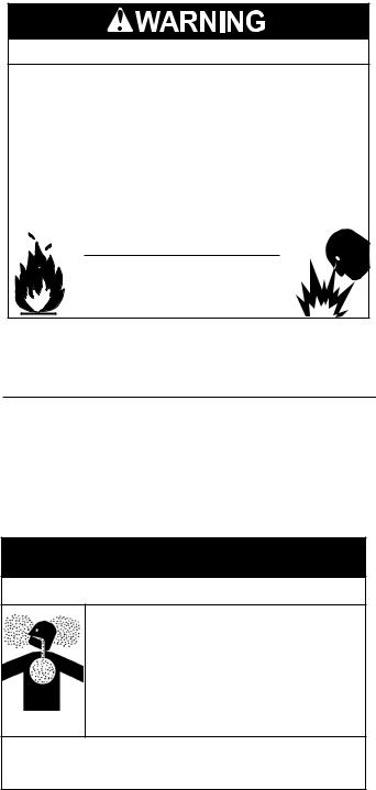
WARNING: If the information in these instructions is not followed exactly, a fire or explosion may result causing property damage, personal injury or death.
Do not store or use gasoline or other flammable vapors and liquids in the vicinity of this or any other appliance.
WHAT TO DO IF YOU SMELL GAS:
•Do not try to light any appliance.
•Do not touch any electrical switch; do not use any phone in your building.
•Immediately call your gas supplier from a neighbor’s phone. Follow the gas supplier’s instructions.
•If you cannot reach your gas supplier, call the fire department.
Installation and service must be performed by a qualified installer, service agency or the gas supplier.
Thank you for buying this energy efficient water heater. We appreciate your confidence in our products.
MODELS (A/S/M) TX-199 SERIES 100 & 101 INSTALLATION - OPERATION - SERVICE - MAINTENANCE
Read and understand this instruction manual and the safety messages herein before installing, operating or servicing this water heater.
Failure to follow these instructions and safety messages could result in death or serious injury.
This manual must remain with the water heater.
• For Your Safety •
AN ODORANT IS ADDED TO THE GAS USED
BY THIS WATER HEATER.
KEEP THIS MANUAL IN THE POCKET ON HEATER FOR FUTURE REFERENCE WHENEVER MAINTENANCE ADJUSTMENT OR SERVICE IS REQUIRED.
PRINTED 0118 |
100298175 2000544629 (Rev. B) |

TABLE OF CONTENTS |
GENERAL SAFETY INFORMATION 4
Precautions 4 Grounding Instructions 4 Hydrogen Gas Flammable 4
INTRODUCTION 6
Abbreviations Used 6 Qualifications 6 Preparing for the Installation 6
FEATURES AND COMPONENTS 7 Basic Operation 7 INSTALLATION CONSIDERATIONS 10
Rough-In Dimensions 10 Locating the Water Heater 11 Vent Piping Options 12 Hard Water 12 Circulation Pumps 12
INSTALLATION REQUIREMENTS 13
Gas Supply Pressure Requirements 13 Supply Gas Regulator 14 Power Supply 14 Mixing Valves 14 Dish-washing Machines 15 Closed Water Systems 15 Thermal Expansion 15 Safety Valve Requirements 16 Condensate Drain 17 Combustible Material Storage 17 Ventilation Requirements 18 Direct Vent Installations 22 Single-Vent Installations 23 Stainless Steel Vent Installations 24 Common Direct Venting Requirements 26 Common Direct-Venting System 26
Concentric Termination Installation Preparation 28
Air Requirements 30
INSTALLATION REQUIREMENTS - COMMONWEALTH OF MASSACHUSETTS 32
Installing Carbon Monoxide Detectors 32 Approved Carbon Monoxide Detectors 32 Signage 32 Inspection 32 Exemptions 32
Manufacturer Requirements - Gas Equipment Venting System Provided 32
Manufacturer Requirements - Gas Equipment Venting System Not Provided 32
HIGH-ALTITUDE INSTALLATIONS 33
Termination Clearances for Sidewall Installations 34
Clearances For Rooftop Terminations 36
WATER HEATER INSTALLATION 37
Water Heating Unit Condensate Drain 37 Supply Gas Line Installation 39 Measuring Inlet Gas Pressure 42 Supply Gas Pressure Adjustment 42 Gas Line Connection 43 Gas Line Leak Testing 43 Purging 43 Electrical Connections 43 Water Line Connections 44 T&P Valve Discharge Pipe 44
TEMPERATURE REGULATION 46
High Temperature Limit Control (ECO) 46
Thermostat Control 46 Firing Rate Modulation 46 High Temperature Applications 46
CONTROL SYSTEM OPERATION 47 Temperature Remote Controller 47 START UP 49
Prior to Start up 49 Initial Operation 49 Flow Rates 49 Lighting the Water Heater 50 Normal Operation 52 Setting the Outlet Water Temperature 52 Default Outlet Temperature 53 Setting Units of Measure 53 Freeze Protection System 53
TROUBLESHOOTING 54
Installation Checklist 54 Operational Problems 54 Replacement Parts 56 General Fault and Alert Conditions 56 Troubleshooting Chart 57 Error Codes 58
Water Heating Unit Controller Fault and Alert Conditions 59 MAINTENANCE 61
General 61 Precautions 61
Water heating unit Maintenance and Service 61
Drain Valve 63 Vent System Maintenance 63
DIAGRAMS 64
Wiring Diagram 64 Circulation Pump Wiring Diagrams 65 Water Piping Diagrams 66
2
SAFE INSTALLATION, USE, AND SERVICE |
The proper installation, use, and servicing of this water heater is extremely important to your safety and the safety of others.
Many safety-related messages and instructions have been provided in this manual and on your own water heater to warn you and others of a potential injury hazard. Read and obey all safety messages and instructions throughout this manual. It is very important that the meaning of each safety message is understood by you and others who install, use, or service this water heater.
This is the safety alert symbol. It is used to alert you to potential personal injury hazards. Obey all safety messages that follow this symbol to avoid possible injury or death.
DANGER indicates an imminently
DANGER hazardous situation which, if not avoided, will result in injury or death.
WARNING indicates a potentially hazardous
WARNING situation which, if not avoided, could result in injury or death.
CAUTION indicates a potentially hazardous
CAUTION situation which, if not avoided, could result in minor or moderate injury.
CAUTION used without the safety alert CAUTION symbol indicates a potentially hazardous
situation which, if not avoided, could result in property damage.
All safety messages will generally tell you about the type of hazard, what can happen if you do not follow the safety message, and how to avoid the risk of injury.
APPROVALS

 R
R


 D
D
3
GENERAL SAFETY INFORMATION |
PRECAUTIONS
DO NOT USE THIS WATER HEATER IF ANY PART HAS BEEN EXPOSED TO FLOODING OR WATER DAMAGE.
Immediately call a qualified service agency to inspect the water heater and to make a determination on what steps should be taken next.
If the unit is exposed to the following, do not operate heater until all corrective steps have been made by a qualified service agency.
1.External fire.
2.Damage.
3.Firing without water.
GROUNDING INSTRUCTIONS
This water heater must be grounded in accordance with the National Electrical Code and/or local codes. These codes must be followed in all cases. Failure to ground this water heater properly may also cause erratic control system operation.
This water heater must be connected to a grounded metal, permanent wiring system; or an equipment grounding conductor must be run with the circuit conductors and connected to the equipment grounding terminal or lead on the water heater.
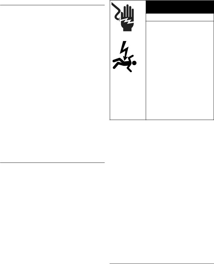
HYDROGEN GAS FLAMMABLE
Explosion Hazard
 Flammable hydrogen gases may be present.
 Keep all ignition sources away from faucet when turning on hot water.
Hydrogen gas can be produced in a hot water system served by this water heater that has not been used for a long period of time (generally two weeks or more). Hydrogen gas is extremely flammable. To reduce the risk of injury under these conditions, it is recommended that a hot water faucet served by this water heater be opened for several minutes before using any electrical appliance connected to the hot water system. If hydrogen is present there will probably be an unusual sound such as air escaping through the pipe as the water begins to flow. THERE SHOULD BE NO SMOKING OR OPEN FLAME NEAR THE FAUCET AT THE TIME IT IS OPEN.
Verify the power to the water heater is turned off before performing any service procedures. The Enable /Disable switch on front panel disables the 24-volt gas valve. Electrical supply must be turned off at circuit breaker serving water heater.
Read and understand this instruction manual and the safety messages herein before installing, operating or servicing this water heater.
Failure to follow these instructions and safety messages could result in death or serious injury.
This manual must remain with the water heater.
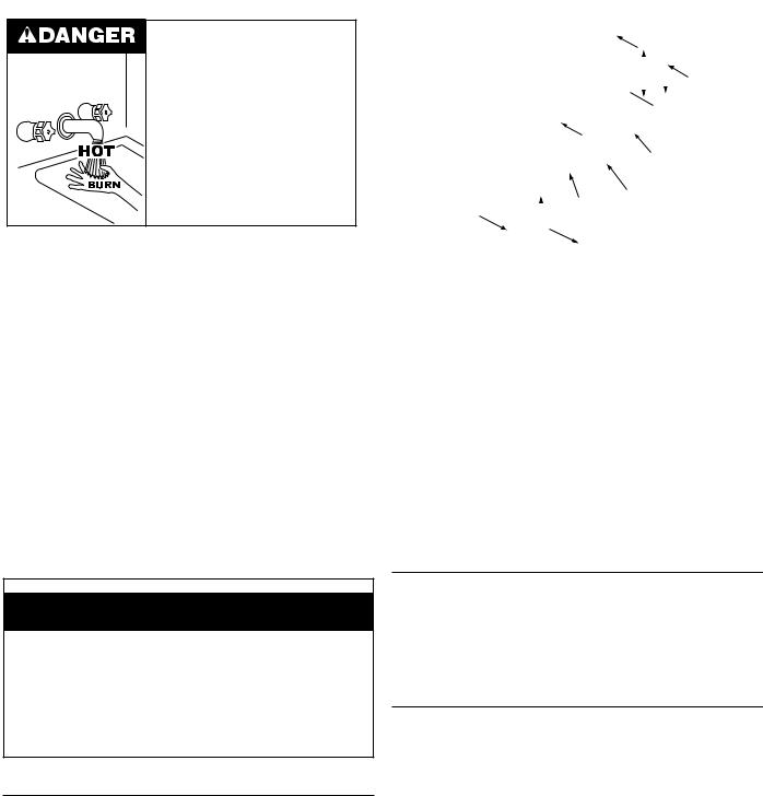
Water temperature over 125°F (52°C) can cause severe burns instantly resulting in severe injury or death.
Children, the elderly and the physically or mentally disabled are at highest risk for scald injury.
Feel water before bathing or showering.
Temperature limiting devices such as mixing valves must be installed when required by codes and to ensure safe temperatures at fixtures.
Explosion Hazard
 Overheated water can cause water tank explosion.
 Properly sized temperature and pressure relief valve must be installed in the opening provided.
CAUTION
Improper installation, use and service may result in property damage.
•Do not operate water heater if exposed to flooding or water damage.
•Inspect anode rods regularly, replace if damaged.
•Install in location with drainage.
•Fill tank with water before operation.
•Properly sized thermal expansion tanks are required on all closed water systems.
Refer to this manual for installation and service.
4

Fire or Explosion Hazard
 Do not store or use gasoline or other flammable vapors and liquids in the vicinity of this or any other appliance.
 Avoid all ignition sources if you smell gas.
 Do not expose water heater controls to excessive gas pressure.
 Use only the gas shown on the water heater rating label.
 Maintain required clearances to combustibles.
 Keep ignition sources away from faucets after extended periods of non-use.
Read instruction manual before installing, using or servicing water heater.
Breathing Hazard - Carbon Monoxide Gas
 Do not obstruct water heater air intake
with insulating blanket.
 Gas and carbon monoxide detectors
are available.
 Install water heater in accordance with
the instruction manual.
Breathing carbon monoxide can cause brain damage or death. Always read and understand instruction manual.
CAUTION
Property Damage Hazard
•All water heaters eventually leak.
•Do not install without adequate drainage.
Electrical Shock Hazard
•Turn off power at the branch circuit breaker serving the water heater before performing any service.
•Label all wires prior to disconnecting when performing service. Wiring errors can cause improper and dangerous operation.
•Verify proper operation after servicing.
•Failure to follow these instructions can result in personal injury or death.
5
Fire Hazard
For continued protection against risk of fire:
 Do not install water heater on carpeted floor.
 Do not operate water heater if exposed to flooding or water damage.
Fire and Explosion Hazard
 Use joint compound or Teflon tape compatible with propane gas.
 Leak test gas connections before placing water heater in operation.
 Disconnect gas piping at main gas shutoff valve before leak testing heater.
 Install sediment trap in accordance with NFPA 54 or CAN/CSA B149.1.
Fire and Explosion Hazard
 Do not use water heater with any gas other than the gas shown on the rating label.
 Excessive gas pressure to gas valve can cause serious injury or death.
 Turn off gas lines during installation.
 Contact a qualified installer or service agency for installation and service.
Jumping out control circuits or components can result in property damage, personal injury or death.
•Service should only be performed by a qualified service technician using proper test equipment.
•Altering the water heater controls and/or wiring in any way could result in permanent damage to the controls or water heater and is not covered under the limited warranty.
Any bypass or alteration of the water heater controls and/or wiring will result in voiding the appliance warranty.

INTRODUCTION
Thank You for purchasing this water heater. Properly installed and maintained, it should give you years of trouble free service.
ABBREVIATIONS USED
Abbreviations found in this Instruction Manual include :
•ANSI - American National Standards Institute
•ASME - American Society of Mechanical Engineers
•AHRI - Air Conditioning, Heating and Refrigeration
Institute
•NEC - National Electrical Code
•NFPA - National Fire Protection Association
•UL - Underwriters Laboratory
•CSA - Canadian Standards Association
QUALIFICATIONS
Installation and service of this water heater requires ability equivalent to that of a Qualified Agency (as defined by ANSI below) in the field involved. Installation skills such as plumbing, air supply, venting, gas supply and electrical supply are required in addition to electrical testing skills when performing service.
ANSI Z223.1 2015 Sec. 3.3.81: “Qualified Agency” - “Any individual, firm, corporation or company that either in person or through a representative is engaged in and is responsible for (a) the installation, testing or replacement of gas piping or (b) the connection, installation, testing, repair or servicing of appliances and equipment; that is experienced in such work; that is familiar with all precautions required; and that has complied with all the requirements of the authority having jurisdiction.”
If you are not qualified (as defined by ANSI above) and licensed or certified as required by the authority having jurisdiction to perform a given task do not attempt to perform any of the procedures described in this manual. If you do not understand the instructions given in this manual do not attempt to perform any procedures outlined in this manual.
PREPARING FOR THE INSTALLATION
1.Read the entire manual before attempting to install or operate the water heater. Pay close attention to the
General Safety Information (page 4). If you don’t follow the safety rules, the water heater may not operate safely. It could cause property damage, injury and/or death.
•This manual contains instructions for the installation, operation, and maintenance of the water heater. It also contains warnings throughout the manual that you must read and be aware of. All warnings and all instructions are essential to the proper operation of the water heater and your safety.
•Detailed installation diagrams are also found in this manual. These diagrams will serve to provide the installer with a reference. It is essential that all venting, water piping, gas piping, and wiring be installed as shown.
•Particular attention should be given to the installation of thermometers at the locations indicated in the piping diagrams as these are necessary for checking the operation of the water heater.
•The principal components of the water heater are identified in Features and Components (page
7)in this manual. Use this reference to locate and identify various components on the water heater.
•See Troubleshooting (page 54). By using this checklist the user may be able to make minor operational adjustments and avoid unnecessary service calls. However, service and diagnostic procedures should be performed only by a Qualified Service Agency.
NOTE: Costs to correct installation errors are not covered under the limited warranty. See the
Commercial Water Heater Limited Warranty provided with this water heater.
2.Be sure to turn off power when working on or near the electrical system of the water heater. Never touch electrical components with wet hands or when standing in water.
3.The installation must conform to all instructions contained in this manual and the local code authority having jurisdiction.These shall be carefully followed in all cases. Authorities having jurisdiction should be consulted before installation begins if there are any questions regarding compliance with local, state or national codes.
•In the absence of local codes, the installation must comply with the current editions of the National Fuel Gas Code, ANSI Z223.1/NFPA 54 and the National Electrical Code, NFPA 70 or CAN/CSA-B149.1, the Natural Gas and Propane Installation Code, and CSA C22.1, the Canadian Electrical Code.
All documents are available from the Canadian Standards Association, Corporate Head Office 178 Rexdale Blvd.Toronto, ONCanada M9W 1R3.
•NFPAdocuments are also available from the National Fire Protection Association, 1 Batterymarch Park, Quincy, MA 02269.
4.After reading this manual, if you have any questions or do not understand any portion of the instructions, call the toll free number on the back cover of this manual for technical assistance. In order to expedite your request, please have the full Model, Serial and Series numbers of the water heater you are working with available for the technician. This information is located on the water heater’s rating label.
5.Carefully plan the placement of the water heater. Examine the location to ensure that it complies with the requirements in Locating the Water Heater (page 11) and the Rough-In Dimensions (page 10).
6
6.For installation in California this water heater must be braced or anchored to avoid falling or moving during an earthquake. See instructions for correct installation procedures. Instructions may be obtained from California Office of the State Architect, 1102 Q Street, Suite 5100, Sacramento, CA 95811.
7.Massachusetts Code requires this water heater to be installed in accordance with Massachusetts 248-CMR 2.00: State Plumbing Code and 248-CMR 5. See Installing Carbon Monoxide Detectors (page 32).
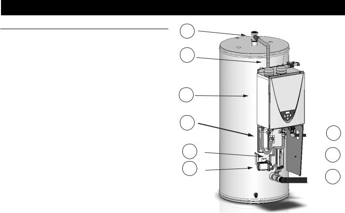
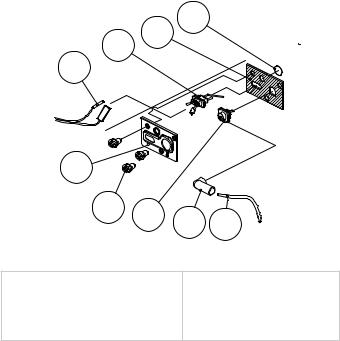
FEATURES AND COMPONENTS
BASIC OPERATION
This gas water heater combines features of a conventional tank water heater and a tankless water heater to achieve high efficiency as well as high-volume on-demand availability.
When hot water is being used, hot water is drawn from the top of the storage tank. As the tank water is used, it is replenished by cold water from the water supply through the cold water inlet at the bottom of the tank. When the temperature of the water in the storage tank falls below a set point, the controller runs the pump, which draws cold water from either the bottom of the tank or the supply (depending on the hot water draw flow), sends it through the tankless heater, and then to the hot water outlet fitting at the top of the tank.
If hot water is being used, the heated water moves through the outlet fitting to the faucet or appliance. If demand for hot water is high enough, additional hot water is drawn from the top of the tank. If hot water is not being used, the heated water from the tankless unit recirculates back into the tank at the top until the temperature in the tank reaches the set point. See Figure 3.
1
2
3
2
4
5
 8
8  7
7
 6
6
Figure 1. TX1 Components
1. |
Hot Water Outlet Fitting |
5. |
Pump |
2. |
Piping from Water Heating Unit to Tank |
6. |
Cold Water Inlet |
3. |
Water Heating Unit |
7. |
Controller |
4. |
Piping from Tank to Pump |
8. |
Gas Supply |
7
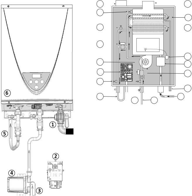
WATER HEATING UNIT COMPONENTS |
|
|
|
|
||||||||
|
1 |
|
|
|
|
|
|
|
|
|
|
18 |
|
|
|
|
|
|
|
|
|
|
|
||
|
|
|
|
|
|
|
|
|||||
|
2 |
|
|
|
|
|
|
|
|
|
|
|
|
3 |
|
|
|
|
|
|
|
|
17 |
||
|
|
|
|
|
|
|
|
|
|
16 |
||
|
|
|
|
|
|
|
|
|
||||
|
4 |
|
|
|
|
|
|
|
15 |
|||
|
|
|
|
|
|
|
|
|||||
|
|
|
|
|
|
|
|
|
||||
|
5 |
|
|
|
|
|
|
|
14 |
|||
|
|
|
|
|
|
|
|
|||||
|
|
|
|
|
|
|
|
|
||||
|
6 |
|
|
|
|
|
|
|
13 |
|||
|
|
|
|
|
|
|
|
|||||
|
7 |
|
|
|
|
|
|
|
||||
|
|
|
|
|
|
|
|
12 |
||||
|
|
|
|
|
|
|
|
|||||
|
|
|
|
|
|
|
|
|
||||
|
8 |
|
|
|
|
|
|
10 |
11 |
|
|
|
|
|
|
|
|
|
|
|
|||||
|
9 |
|
|
|
|
|
|
|||||
|
|
|
|
Figure 3. Water Heating Unit |
||||||||
1. |
Combustion Air Intake Port |
10. |
Cold Water Inlet |
|||||||||
2. |
Exhaust Thermistor |
11. |
Gas Supply Inlet |
|||||||||
3. |
Heated Water Thermistor |
12. |
Condensate Drain Port |
|||||||||
4. |
Bypass Valve |
13. |
Fan Motor |
|||||||||
5. |
Water Control Valve |
14. |
Gas Control Valve |
|||||||||
6. |
Computer Board |
15. |
Igniter |
|||||||||
7. |
Hot Water Outlet Thermistor |
16. |
Primary Heat Exchanger |
|||||||||
8. |
Piping to Outlet Fitting |
17. |
Secondary Heat Exchanger |
|||||||||
9. |
Cold Water Inlet Thermistor |
18. |
Exhaust Port |
|||||||||
Figure 2. Water Heater Function
1. |
Gas Supply Valve |
4. |
Pump |
2. |
Controller |
5. |
Piping to Outlet Fitting |
3. |
Cold Water from Bottom of Tank |
6. |
Water Heating Unit |
8
MODULATION
The water heaters covered by this manual are capable of modulating their firing rate. The function of the water heating unit is controlled by a computer printed circuit board. The computer monitors the water temperature measured by the cold water inlet thermistor and hot water outlet thermistor.
Another controller monitors the temperature in the tank. If the tank temperature falls below the set point, this controller runs the pump. As cold water from the bottom of the tank runs into the water heating unit, the thermistors will detect the change in temperature. When the temperatures fall below the set point, the burner is ignited, heating it until the thermistors in the water heating unit and in the tank warm to their set points.
BURNER ASSEMBLY Spark Igniter
The control system energizes the spark ignition transformer with 120 VAC during the ignition cycle. The spark ignition transformer then sends a high-voltage current to the spark igniter which in turn ignites the main burner air/gas mixture.
1
3 2
4
|
5 |
|
|
|
|
6 |
7 |
8 |
9 |
|
|
|||
|
|
|
||
|
Figure 4. Igniter Assembly |
|||
1. |
Burner Window |
|
6. |
Pan screw M4x8 MFZN |
2. |
Rod holder gasket |
|
7. |
Igniter rod |
3. |
Flame rod |
|
8. |
Rod cap |
4. |
Flame rod wire |
|
9. |
Igniter assembly |
5. |
Rod holder |
|
|
|
Flame Sensor
The control system also monitors the flame sensor to confirm a flame is present at the main burner. If a flame is not verified during the ignition trial period (3-5 seconds) the control system will immediately close the gas valve.
9
INSTALLATION CONSIDERATIONS
ROUGH-IN DIMENSIONS
Hot Water Outlet
Combustion Air Inlet |
T&P Valve |
and Exhaust Outlet |
|
|
|
|
|
|
|
|
|
|
|
|
|
|
C |
|
A |
F |
B |
||
|
|
|
|
|
|
|
 Supply Gas Connection
|
|
|
|
|
|
|
|
|
|
|
|
|
|
|
|
|
|
|
|
|
|
|
|
|
|
|
|
|
|
|
G |
|
|
|
|
|
|
|
|
|
|
|
|
||||
|
|
|
|
|
|
|
|
|
|
|
|
|
|
|
|
ValveDrain |
|
E |
|
|
|
|
|
|
|
|
|
|
|
|
|
|
|
|
|
|
|
|
|
|
|
|
|
||||
|
|
|
|
|
|
|
|
|
|
|
|
|
|
|
|
|
|
|
|
|
|
|
|
|
|
|
|
|
|
|
|
|
|
|
|
|
|
|
|
|
|
||||||
|
|
|
|
|
|
|
|
|
|
|
|
|
|
|
|
|
|
|
|
|
|
|
|
|
|
|
|
|
|
|
|
|
|
|
|
|
|
|
|
|
|
||||||
|
|
|
|
|
|
|
|
|
|
|
|
|
|
|
|
|
|
|
|
|
|
|
|
|
|
|
|
|
|
|
|
|
|
|
|
|
|
|
|
|
|
||||||
|
|
|
|
|
|
D |
|
|
|
|
|
|
|
|
|
|
|
|
|
|
|
|
|
Cold Water |
|
|
|
|
|
|
|
|
|
||||||||||||||
|
|
|
|
|
|
|
|
|
|
|
|
|
|
|
|
|
|
|
|
|
|
|
|
|
|
|
|
|
|
|
|
|
|
|
|
|
|
|
|
|
|
||||||
|
|
|
|
|
|
|
|
|
|
|
|
|
|
|
|
|
|
|
|
|
|
|
|
|
|
|
|
|
|
|
|
|
Inlet |
|
|
|
|
|
|
|
|
|
|||||
|
|
|
|
|
|
|
|
|
|
|
|
|
|
|
|
|
|
|
|
|
|
|
|
|
|
|
|
|
|
|
|
|
|
|
|
|
|
|
|
|
|
||||||
|
|
|
|
|
|
|
|
|
|
|
|
|
|
|
|
|
|
|
|
Figure 5. Rough-in Dimensions |
|
|
|
|
|
|
|
|
|
|
|
|
|||||||||||||||
|
|
|
|
|
|
|
|
|
|
|
|
|
|
|
|
|
|
|
|
|
|
|
|
|
|
|
|
|
|
|
|
|
|
|
|
|
|
|
|
|
|
|
|
|
|||
|
|
|
|
|
|
|
|
|
|
|
|
|
|
|
|
|
|
|
|
Table 1. Dimensions |
|
|
|
|
|
|
|
|
|
|
APPROX. |
|
|
|
|
|
|||||||||||
|
|
|
|
|
|
|
|
|
|
|
|
A |
|
B |
|
|
C |
|
|
D |
|
E |
F |
|
|
|
|
|
G |
SHIP WEIGHT |
|
|
|
|
|
||||||||||||
|
|
|
|
|
|
|
|
|
|
|
|
|
|
|
|
|
|
|
|
|
|
|
|
|
|
|
|
|
|
|
|
||||||||||||||||
|
|
|
|
|
|
|
|
|
|
Inches (cm) |
Inches (cm) |
Inches (cm) |
Inches (cm) |
Inches (cm) |
Inches (cm) |
Inches (cm) |
|
LBS (KG) |
|
|
|
|
|
||||||||||||||||||||||||
|
|
|
|
|
|
|
|
|
|
|
|
|
|
|
|
|
|
|
|
|
|
|
|
|
|
|
|
|
|
|
|
|
|
|
|
|
|
|
|
|
|
|
|
||||
|
|
|
|
|
|
|
|
|
|
72 (183) |
|
58.7 (149) |
|
|
41 (104) |
|
11.8 (30) |
4.3 (11) |
|
61.38 |
|
|
|
|
30 (76) |
|
520(236) |
|
|
|
|
|
|||||||||||||||
|
|
|
|
|
|
|
|
|
|
|
|
|
|
|
|
|
|
|
|
|
|
|
|
|
|
|
|
|
|
|
|
|
|
|
|
|
|
|
|
|
|||||||
|
|
|
|
|
|
|
|
|
|
|
|
|
|
|
|
Table 2. GAS PRESSURE REQUIREMENTS |
|
|
|
|
|
|
|
|
|
||||||||||||||||||||||
|
|
|
|
|
|
|
|
|
|
|
|
|
|
|
|
|
|
|
|
|
|
|
|
|
|
|
|
|
|
|
|
|
|
|
|||||||||||||
|
|
|
|
|
|
*Manifold Pressure |
|
|
|
|
|
|
|
Minimum Supply Pressure |
|
|
|
|
|
Maximum Supply Pressure |
|
|
|
||||||||||||||||||||||||
|
|
|
NATURAL GAS |
|
PROPANE GAS |
|
NATURAL GAS |
|
PROPANE GAS |
|
|
|
|
NATURAL GAS |
PROPANE GAS |
|
|
||||||||||||||||||||||||||||||
|
|
2.95" W.C. (0.73 kPa) |
|
3.3" W.C. (0.82 kPa) |
|
4.0” W. C. (1.00 kPa) |
|
8.0” W. C. (1.99 kPa) |
10.5” W. C. (2.61 kPa) |
14” W. C. (3.49 kPa) |
|
|
|||||||||||||||||||||||||||||||||||
|
|
|
|
|
|
|
|
|
|
|
|
|
|
|
|
|
|
|
|
Table 3. RECOVERY CAPACITIES |
|
|
|
|
|
|
|
|
|
|
|
|
|||||||||||||||
|
|
|
|
|
|
|
|
|
|
|
|
|
|
|
|
|
|
|
|
|
|
|
|
|
|
|
|
|
|
|
|
|
|
|
|
|
|||||||||||
|
|
|
|
|
|
|
|
|
|
|
|
|
|
|
|
|
|
|
|
|
|
|
|
|
|
U. S. Gallons/hr & liters/hr at temperature rise indicated |
|
|
|
||||||||||||||||||
Type of |
|
|
|
|
Input |
|
|
Thermal |
°F |
|
|
30°F |
|
40°F |
50°F |
|
60°F |
|
70°F |
|
80°F |
|
90°F |
|
100°F |
|
110°F |
120°F* |
130°F* |
140°F* |
|||||||||||||||||
Gas |
|
|
Btu/hr |
|
kW |
|
Efficiency% |
°C |
|
|
17°C |
|
22°C |
28°C |
|
33°C |
|
39°C |
|
44°C |
|
50°C |
|
56°C |
|
61°C |
67°C |
72°C |
78°C |
||||||||||||||||||
Natural |
|
|
199000 |
|
58.32 |
|
96 |
|
GPH |
|
|
772 |
|
|
579 |
463 |
|
386 |
|
331 |
|
289 |
|
257 |
|
232 |
|
211 |
|
193 |
178 |
|
165 |
||||||||||||||
Propane |
|
|
|
|
LPH |
|
|
2922 |
|
|
2192 |
1753 |
|
1461 |
|
1253 |
|
1094 |
|
973 |
|
878 |
|
799 |
|
731 |
674 |
|
625 |
||||||||||||||||||
|
|
|
|
|
|
|
|
|
|
|
|
|
|
|
|
|
|
|
|
|
|
|
|
||||||||||||||||||||||||
* inlet water 40° F |
(22° C) |
|
|
|
|
|
|
|
|
|
|
|
|
|
|
|
|
|
|
|
|
|
|
|
|
|
|
|
|
|
|
|
|
|
|
|
|
|
|
|
|||||||
Water Connection Size: Inlet/Outlet 2" Female NPT
Supply Gas Connection: 3/4" Male NPT
10
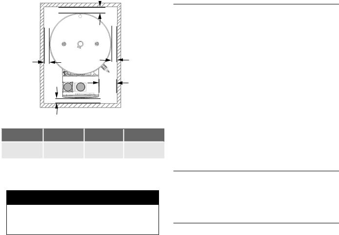
LOCATING THE WATER HEATER
Carefully choose a location for the new water heater. The placement is a very important consideration for the safety of the occupants in the building and for the most economical use of the water heater.
CAUTION
Property Damage Hazard
•All water heaters eventually leak.
•Do not install without adequate drainage.
Whether replacing an existing water heater or installing the water heater in a new location observe the following critical points:
1.The water heater must not be located in an area where it will be subject to freezing temperatures.
2.Locate the water heater so it is protected and not subject to physical damage by a moving vehicle.
3.Locate the water heater on a level surface.
4.Locate the water heater near a floor drain. The water heater should be located in an area where leakage of the tank or connections will not result in damage to the area adjacent to the water heater or to lower floors of the structure. When such locations cannot be avoided, it is recommended that a metal drain pan, adequately drained, be installed under the water heater.
5.Locate the water heater close to the point of major hot water usage.
6.Locate the water heater close to a 120 VAC power supply. See Power Supply (page 14) for requirements.
7.Locate the water heater where an adequate supply of fresh air for combustion and ventilation can be obtained.
See Air Requirements (page 30).
8.Locate the water heater where the vent and intake air piping, when installed, will remain within the maximum equivalent lengths allowed. See Maximum Equivalent Pipe Lengths and Elbows (page 21).
Fire or Explosion Hazard
 Do not store or use gasoline or other flammable vapors and liquids in the vicinity of this or any other appliance.
 Avoid all ignition sources if you smell gas.
 Do not expose water heater controls to excessive gas pressure.
 Use only the gas shown on the water heater rating label.
 Maintain required clearances to combustibles.
 Keep ignition sources away from faucets after extended periods of non-use.
Read instruction manual before installing, using or servicing water heater.
9.There is a risk in using fuel burning appliances such as gas water heaters in rooms, garages or other areas where gasoline, other flammable liquids or engine driven equipment or vehicles are stored, operated or repaired. Flammable vapors are heavy and travel along the floor and may be ignited by the water heater’s igniter or Main Burner flames causing fire or explosion.
10.Flammable items, pressurized containers or any other potential fire hazardous articles must never be placed on or adjacent to the water heater.
CLEARANCE TO COMBUSTIBLE MATERIALS
The water heaters covered in this manual are approved for installation on combustible flooring. The clearance to combustible and non combustible construction materials is zero inches on the back and sides of the water heater. These water heaters are also approved for installation in an alcove.
There is a three inch (76 mm) clearance from the left and right sides of the water heating unit to combustible and non-combustible surfaces.
11
 0” Min.
|
0” Min. |
|
0” Min. |
|
|
|
|
|
|
3” Min. |
|
|
4” Min. |
|
|
|
Figure 6. Clearances |
|
|
Top |
Bottom |
Front |
Sides |
4 in. (102 mm) |
0 in. (0 mm) |
4 in. (102 mm) |
0 in. (0 mm) |
Note: Adequate clearance for servicing should be maintained on all installations.
See Service Clearance.
 WARNING
Maintain all clearances around the water heater. Failure to do so could create a fire hazard, potentially leading to death, serious injury, and/or property damage.
When the water heater is installed directly on carpeting, the water heater shall be installed on a metal or wood panel extending beyond the full width and depth of the water heater by at least three inches (76.2 mm) in any direction or, if the water heater is installed in an alcove or closet, the entire floor shall be covered by the panel. The panel must be strong enough to carry the weight of the heater when full of water.
SERVICE CLEARANCE
A service clearance of 24 inches (61 cm) should be maintained from serviceable parts such as the T&P valve, control system components, gas valve, drain valve. A service clearance of 50 inches (127 cm) should be maintained from top for anode replacement.
INTAKE AIR AND VENT PIPE CLEARANCES
The minimum clearance from combustible materials for the vent (exhaust) and intake air piping shall be 0 inches. Vent or intake air piping passing through a combustible wall or ceiling must be a continuous run (no joints).
VENT PIPING OPTIONS
EXTENDED VENT LENGTH
The water heaters covered by this manual can be installed using four-inch pipe for the intake air and/or vent piping up to a maximum of 120 equivalent feet (15.2 m).
Vent terminations are supplied with the heater. All runs must comply with Table 7 (page 21).
Contact your local supplier or the parts department to order vent terminals.
OPTIONAL DIRECT VENT TERMINATIONS
The water heaters covered in this manual can be installed in a direct vent configuration using optional concentric terminations. See Concentric Termination Installation Preparation (page 28).
Concentric terminations must be ordered separately. Contact your local distributor or call the parts department phone number listed on the back cover of this manual to order.
HARD WATER
Where hard water conditions exist, water softening or the threshold type of water treatment is recommended. This will protect the dishwashers, coffee urns, water heaters, water piping and other equipment. See Maintenance (page 61) for sediment and lime scale removal procedures.
CIRCULATION PUMPS
A circulating pump is used when a system requires a circulating loop or there is a storage tank used in conjunction with the water heater. See Water Piping Diagrams (page 66) for installation location of circulating pumps.
When the water heater is used with a building recirculation system, the building recirculation flow should be no greater than 1 GPM. Also, for maximum energy efficiency, the recirculation system should be on a timer so that it won’t run continuously without actual hot water usage.
See Circulation Pump Wiring Diagrams (page 65) for electrical hookup information. Install in accordance with the current edition of the National Electrical Code, NFPA 70 or the Canadian Electrical Code, CSA C22.1.
Stainless steel circulating pumps are recommended for use with commercial water heaters.
Refer to the circulating pump manufacturer’s instructions for its operation, lubrication, and maintenance instructions.
12
INSTALLATION REQUIREMENTS
GAS SUPPLY PRESSURE REQUIREMENTS
Low-pressure gas supply systems are defined as those systems that cannot under any circumstances exceed 14” W.C. (1/2 PSI Gauge). These systems do not require pressure regulation. Measurements should be taken to insure that gas pressures are stable and fall within the requirements stated on the water heater rating plate. Take the measurements with all gas burning equipment off (static pressure) and with all gas burning equipment running at maximum rate (dynamic pressure).The gas supply pressure must be stable within 1.5” W.C. from static to dynamic pressure for best performance. Pressure drops that exceed 1.5” W.C. may cause rough starting, noisy combustion or nuisance outages. Increases or spikes in static pressure during off cycles may cause failure to ignite or in severe cases damage to appliance gas valves. If your low-pressure system does NOT meet these requirements, the installer is responsible for the corrections.
High Pressure supply systems use pressures that exceed 14” W.C. (1/2 PSI Gauge). These systems must use fieldsupplied regulators to lower the gas pressure to less than 14” W.C. (1/2 PSI Gauge). Water heaters require gas regulators that are properly sized for the water heater input and deliver the rating-plate specified pressures. Gas supply systems in which the pressure exceeds 5 PSI often require multiple regulators to achieve desired pressures. Systems in excess of 5 PSI pressure should be designed by gas delivery professionals for best performance. Water heaters connected to gas supply systems that exceed 14” W.C. (1/2 PSI Gauge) at any time must be equipped with a gas supply regulator.
 WARNING
Breathing, Fire, and
Explosion Hazard
Do not use this water heater with any gas other than the one listed on the rating plate.
Ensure that any and all gas regulators used are operating properly and providing gas pressures within the specified range shown below. Excess gas inlet pressure may cause serious accidents.
Conversion of this unit from natural gas to propane or vice versa will void all warranties. Contact your local distributor to get the correct unit for your gas type. The manufacturer is not liable for any property and/or personal damage resulting from gas conversions.
Failure to observe these warnings could result in severe personal injury, carbon monoxide poisoning, or death.
The following are the minimum and maximum gas pressures required by all models of this appliance:
Table 4. Gas Pressure Parameters by Gas Type
Gas type |
Inlet Gas Pressure |
|
|
|
|
Natural Gas |
Min. 4.0” W.C. (1.00 kPa) |
|
Max. 10.5” W.C. (2.61 kPa) |
||
|
||
Propane |
Min. 8.0” W.C. (1.99 kPa) |
|
Max. 14.0” W.C. (3.48 kPa) |
||
|
Note: Fuel conversions are not allowed on this product.
The gas valve has minimum gas supply pressure limits specified in Table 4. The minimum supply pressure is measured while gas is flowing (dynamic pressure). The supply pressure should never fall below the minimum specified in the table for each type of gas.
The supply pressure should be measured with all gas fired appliances connected to the common main firing at full capacity. If the supply pressure drops more than 1.5” W.C. as gas begins to flow to the water heater, then the supply gas system, including the gas line and/or the gas regulator may be restricted or undersized. SeeSupply Gas Regulator (page 14).
The gas valve has maximum gas supply pressure limits specified in Table 4. The maximum supply pressure is measured while gas is not flowing (static pressure).
Until testing of the main gas line supply pressure is completed, ensure the gas line to the water heater is disconnected to avoid any damage to the water heater.
13
SUPPLY GAS REGULATOR
1.The maximum allowable gas supply pressure for this water heater using either natural gas or propane is specified in Table 4. Install a positive lock-up gas pressure regulator in the gas supply line if inlet gas pressure can exceed these pressures at any time.
2.If a positive lock-up regulator is required, follow these instructions:
a.Positive lock-up gas pressure regulators must be capable of going low enough to support the unit at its lowest firing rate.
b.Positive lock-up gas pressure regulators must be rated at or above the input Btu/hr rating of the water heater they supply.
c.Supply gas regulators shall have inlet and outlet connections not less than the minimum supply gas line size for the water heater they supply. See Table 19 (page 41) and Table 20 (page 41).
d.Positive lock-up gas pressure regulator(s) should be installed no closer than 3 feet (1 meter) and no farther than 8 feet (2.4 meters) from the water heater’s inlet gas connection.
e.After installing the positive lock-up gas pressure regulator(s), an initial nominal supply pressure setting of 7.0” W.C. for natural gas and 10"w.c. for propane gas while the water heater is operating is recommended and will generally provide good water heater operation. Some additional adjustments may be required later to maintain a steady gas supply pressure.
f.When installing multiple water heaters in the same gas supply system, it is recommended that individual positive lock-up gas pressure regulators be installed at each unit from the supply gas connection on the water heater.
POWER SUPPLY
The water heaters covered in this manual require a 120 VAC, 1Ø (single phase), 60 Hz, 15 amp power supply and must also be electrically grounded in accordance with local codes or, in the absence of local codes, with the
National Electrical Code, ANSI/NFPA 70 or the Canadian Electrical Code, CSA C22.1.
 WARNING
Shock or Electrocution Hazard
Follow the electrical code requirements of the local authority having jurisdiction. In the absence of such requirements, follow the current edition of the National Electrical Code ANSI/NFPA 70 in the U.S. or the current edition of CSA C22.1
Canadian Electrical Code Part 1 in Canada.
When servicing or replacing parts within the water heater, label all wires prior to disconnection to facilitate an easy and error-free reconnection. Wiring errors can cause improper and dangerous operation. Verify proper operation after servicing.
Failure to observe these warnings could result in personal injury or death.
DEDICATED POWER WIRING AND BREAKERS
Dedicated power supply wires, neutral wires, ground wiring, and dedicated circuit breakers, often prevent electrical line noise and are required when installing the water heater.
NOTE: This water heater should not be connected to an electrical supply with a Ground Fault Circuit Interrupter (GFCI) or Arc Fault Circuit Interrupter (AFCI) with Integral GFCI protection as defined in NFPA 70, CSA C22.1 and
UL 943.
POWER FLUCTUATIONS AND ELECTRICAL NOISE
The water heater’s control system requires a source of stable clean electricity for proper operation. Connecting the water heater to a branch circuit that is subject to fluctuations in voltage level or electrical line noise such as electromagnetic interference (EMI) or radio frequency interference (RFI) may cause erratic control system operation and malfunction.
A high-quality power supply filter/suppressor must be installed if the above conditions exist. Call the technical support phone number listed on the back cover of this manual or contact a local power filter/suppressor supplier for more information.
NOTE: Malfunctions caused by the power supply and costs to install power supply filters are not covered under the limited warranty. See the Commercial Water Heater Limited Warranty provided with this water heater.
MIXING VALVES
Water heated to a temperature which will satisfy clothes washing, dish washing, and other sanitizing needs can scald and cause permanent injury upon contact. Short repeated heating cycles caused by small hot water uses can cause temperatures at the point of use to exceed the water heater’s
14
temperature setting by up to 20°F (11°C).
Water temperature over 125°F (52°C) can cause severe burns instantly resulting in severe injury or death.
Children, the elderly and the physically or mentally disabled are at highest risk for scald injury.
Feel water before bathing or showering.
Temperature limiting devices such as mixing valves must be installed when required by codes and to ensure safe temperatures at fixtures.
Some people are more likely to be permanently injured by hot water than others. These include the elderly, children, the infirm and the physically/mentally disabled. Table 5 shows the approximate time-to-burn relationship for normal adult skin. If anyone using hot water provided by the water heater being installed fits into one of these groups or if there is a local code or state law requiring a certain water temperature at the point of use, then special precautions must be taken.
In addition to using the lowest possible temperature setting that satisfies the demand of the application, a mixing valve should be installed at the water heater or at the hot water taps to further reduce system water temperature. See
Figure 7 (page 15).
Mixing valves are available at plumbing supply stores. Consult a Qualified Installer or Service Agency. Follow mixing valve manufacturer’s instructions for installation of the valves.
Table 5. Burn Time At Various Temperatures
Water Temperature |
Time for 1st Degree Burn |
imeBurns |
|
2nd & 3rd Degree |
|||
°F (°C) |
(Less Severe Burns) |
||
(Most Severe Burns) |
|||
|
|
||
110 (43) |
(normal shower temp.) |
|
|
116 (47) |
(pain threshold) |
|
|
116 (47) |
35 minutes |
45 minutes |
|
122 (50) |
1 minute |
5 minutes |
|
131 (55) |
5 seconds |
25 seconds |
|
140 (60) |
2 seconds |
5 seconds |
|
149 (65) |
1 second |
2 seconds |
|
154 (68) |
instantaneous |
1 second |
(U.S. Government Memorandum, C.P.S.C., Peter L. Armstrong, Sept. 15, 1978)
DISH-WASHING MACHINES
All dish-washing machines meeting theNational Sanitation Foundation requirements are designed to operate with water flow pressures between 15 and 25 pounds per square inch (103 kPa and 173 kPa). Flow pressures above 25 pounds per square inch (173 kPa), or below 15 pounds per square inch (103 kPa), will result in improperly sanitized dishes. Where pressures are high, a water pressure reducing or flow regulating control valve should be used in the 180°F (82°C) line to the dish-washing machine and should be adjusted to deliver water pressure between these limits.
|
|
HOT WATER |
|||
|
|
OUTLET |
|
|
|
|
|
|
|
||
|
|
|
|
|
|
|
|
|
12” TO 15” |
||
TEMPERED WATER |
(30-38 cm) |
|
|||
|
|
|
|||
|
|
|
|||
|
OUTLET |
|
|
|
|
COLD |
|
|
CHECK |
||
WATER |
|
|
VALVE |
||
INLET |
|
|
MIXING |
||
|
|
CHECK |
|||
|
|
VALVE |
|||
|
|
VALVE |
|||
|
|
|
|
|
|
|
|
TO TANK |
|||
|
|
INLET |
|||
Figure 7. Mixing Valve
The National Sanitation Foundation also recommends circulation of 180°F (82°C) water. The circulation should be just enough to provide 180°F (82°C) water at the point of take-off to the dish-washing machine.
Adjust flow by throttling a full-port ball valve installed in the circulating line on the outlet side of the pump. Never throttle flow on the suction side of a pump. See the Water Piping Diagrams (page 66).
NOTE: To comply with NSF Standard 5 installation requirements, the bottom of the water heater must be sealed to the floor with a silicone based sealant or elevated 6 inches above the floor.
CLOSED WATER SYSTEMS
Water supply systems might have pressure reducing valves, check valves, or back flow preventers installed to meet code requirements or to adapt to such conditions as high line pressure, among others. Devices such as these cause the water system to be a closed system. If the water system is closed, thermal expansion can occur.
THERMAL EXPANSION
As water is heated, it expands (thermal expansion). In a closed system, as the volume of water grows, a corresponding increase in water pressure occurs. The increased pressure caused by the thermal expansion can cause premature tank failure (leakage). This type of failure is not covered under the limited warranty. Thermal expansion can also cause intermittent water discharge from the Temperature-Pressure Relief Valve: water discharged from the valve due to excessive pressure build up. This condition is not covered under the limited warranty. See the Commercial Water Heater Limited Warranty provided with this water heater.
The Temperature-Pressure Relief Valve is not intended for the constant relief of thermal expansion.
15
Athermal expansion tank provides a way to absorb excess pressure caused by thermal expansion.Aproperly sized and pressurized thermal expansion tank must be installed on all closed systems to control the harmful effects of thermal expansion. Contact a local plumbing service agency to have a thermal expansion tank installed.
See Water Line Connections (page 44) and the Water Piping Diagrams (page 66).
SAFETY VALVE REQUIREMENTS
The water heaters covered by this manual require the following safety valves:
•A pressure-only relief valve between the water heating unit outlet fitting and the outlet fitting at the top of the storage tank
•ATemperature and Pressure Relief valve on the storage tank in the customary position
WATER HEATING UNIT PRESSURE-ONLY RELIEF VALVE
The water heater has a high-temperature shutoff switch built in as a standard safety feature (called a Hi-Limit switch) therefore a “pressure only” relief valve is required.
This unit does not come with an approved pressure relief valve, so this must be field supplied.
An approved pressure relief valve must be installed on the water heating unit hot water outlet. The pressure relief valve must conform to ANSI Z21.22 or CAN 1-4.4 and installation must follow local codes. The discharge capacity must be at least 199,000 BTU/h. The pressure relief valve needs to be rated for a maximum of 150 psi (1 MPa).
The discharge piping for the pressure relief valve must be directed so that the hot water cannot splash outward and cause damage or personal injury.
Attach the discharge tube to the pressure relief valve and run the end of the tube to within 6 in (152 mm) from the floor. This discharge tube must allow free and complete drainage without any restrictions.
If the pressure relief valve discharges periodically, this may be due to thermal expansion in a closed water supply system. See Thermal Expansion (page 15) and/or contact the water supplier or a local plumbing professional on how to correct this situation.
Do not plug the pressure relief valve.
The pressure relief valve must be manually operated periodically to check for correct operation. Before operating the valve manually, check that it will discharge in a place for secure disposal.
No valve must be placed between the relief valve and the water heating unit.
TEMPERATURE-PRESSURE RELIEF VALVE
This water heater is provided with a properly rated/sized and certified combination Temperature-Pressure Relief Valve (T&P valve) by the manufacturer. The valve is certified by
a nationally recognized testing laboratory that maintains periodic inspection of production of listed equipment of materials as meeting the requirements for Relief Valves for Hot Water Supply Systems, ANSI Z21.22 • CSA 4.4, and the code requirements of ASME.
Explosion Hazard
 Temperature-Pressure Relief Valve must comply with ANSI Z21.22CSA 4.4 and ASME code.
 Properly sized temperaturepressure relief valve must be installed in opening provided.
 Can result in overheating and excessive tank pressure.
 Can cause serious injury or death.
If replaced, the new T&P valve must meet the requirements of local codes, but not less than a combinationTemperaturePressure Relief Valve rated/sized and certified as indicated in the above paragraph. The new valve must be marked with a maximum set pressure not to exceed the marked hydrostatic working pressure of the water heater (150 psi = 1,035 kPa) and a discharge capacity not less than the water heater Btu/hr or kW input rate as shown on the water heater’s model rating label.
NOTE: In addition to the factory installed TemperaturePressure Relief Valve on the water heater, each remote storage tank that may be installed and piped to a water heating appliance must also have its own properly sized, rated and approved Temperature-Pressure Relief Valve installed. Call the toll free technical support phone number listed on the back cover of this manual for technical assistance in sizing a Temperature-Pressure Relief Valve for remote storage tanks.
For safe operation of the water heater, the TemperaturePressure Relief Valve must not be removed from its designated opening nor plugged. The TemperaturePressure Relief Valve must be installed directly into the fitting of the water heater designed for the relief valve. Install discharge piping so that any discharge will exit the pipe within 6 inches (15.2 cm) above an adequate floor drain, or external to the building. In cold climates, it is recommended that it be terminated at an adequate drain inside the building. Be certain that no contact is made with any live electrical part.The discharge opening must not be blocked or reduced in size under any circumstances. Excessive length, over 30 feet (9.14 m), or use of more than four elbows can cause restriction and reduce the discharge capacity of the valve.
No valve or other obstruction is to be placed between the Temperature-Pressure Relief Valve and the tank. Do not
16
connect discharge piping directly to the drain unless a 6” (15.2 cm) air gap is provided.To prevent bodily injury, hazard to life, or property damage, the relief valve must be allowed to discharge water in adequate quantities if circumstances demand. If the discharge pipe is not connected to a drain or other suitable means, the water flow may cause property damage.
CAUTION
Water Damage Hazard
•Temperature-Pressure Relief Valve discharge pipe must terminate at adequate drain.
T&P VALVE DISCHARGE PIPE REQUIREMENTS
•Shall not be smaller in size than the outlet pipe size of the valve, or have any reducing couplings or other restrictions.
•Shall not be plugged or blocked.
•Shall not be exposed to freezing temperatures.
•Shall be of material listed for hot water distribution.
•Shall be installed so as to allow complete drainage of both the Temperature-Pressure Relief Valve and the discharge pipe.
•Must terminate a maximum of six inches above a floor drain or external to the building. In cold climates, it is recommended that the discharge pipe be terminated at an adequate drain inside the building.
•Shall not have any valve or other obstruction between the relief valve and the drain.

 Burn hazard.
 Hot water discharge.


 Keep clear of TemperaturePressure Relief Valve discharge outlet.
The Temperature-Pressure Relief Valve must be manually operated at least twice a year. Caution should be taken to ensure that (1) no one is in front of or around the outlet of the Temperature-Pressure Relief Valve discharge line, and (2) the water manually discharged will not cause any bodily injury or property damage because the water may be extremely hot. If after manually operating the valve, it fails to completely reset and continues to release water, immediately close the cold water inlet to the water heater,
follow the draining instructions in this manual, and replace theTemperature-Pressure Relief Valve with a properly rated/ sized new one.
NOTE: The purpose of aTemperature-Pressure Relief Valve is to prevent excessive temperatures and pressures in the storage tank. The T&P valve is not intended for the constant relief of thermal expansion. A properly sized thermal expansion tank must be installed on all closed systems to control thermal expansion, see Thermal Expansion and
Closed Water Systems (page 15).
If you do not understand these instructions or have any questions regarding theTemperature-Pressure Relief Valve, call the toll free number listed on the back cover of this manual for technical assistance.
CONDENSATE DRAIN
The water heaters covered in this manual require a drain near the water heater to allow the condensate to drain safely. The condensate accumulates as a by-product of combustion. Condensate drains from the water heating unit through a drain tube to the drain. The condensate drain tube must leave an air gap of two inches and must not be elevated above the condensate drain connection.
If the condensate does not drain properly, it will build up in the water heating unit and interfere with its function.
CONDENSATE PH LEVEL
The condensate that drains from the water heater’s covered in this manual have pH levels between 4.3 and 5.0. Install a commercially available neutralizing kit if required by local codes.
NOTE: Lower pH levels are acidic. Do not connect a metal drain line, such as copper, to the water heater for this reason. See Water Heating Unit Condensate Drain
(page 37).
COMBUSTIBLE MATERIAL STORAGE
Remove any combustible materials, gasoline or any flammable vapors and liquids.
17
Fire or Explosion Hazard
 Do not store or use gasoline or other flammable vapors and liquids in the vicinity of this or any other appliance.
 Avoid all ignition sources if you smell gas.
 Do not expose water heater controls to excessive gas pressure.
 Use only the gas shown on the water heater rating label.
 Maintain required clearances to combustibles.
 Keep ignition sources away from faucets after extended periods of non-use.
Read instruction manual before installing, using or servicing water heater.
Keep water heater area clear and free of combustible materials, gasoline, and other flammable vapors and liquids.
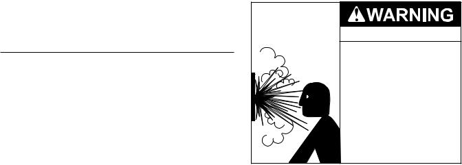
VENTILATION REQUIREMENTS
COMBUSTION AIR SUPPLY
Before installing the water heater, you must determine the amount of air needed to supply this water heater and any other gas appliances in the same area and provide adequate air for combustion and ventilation. Consult a qualified person if you’re unsure of the proper way to supply air to your water heater.
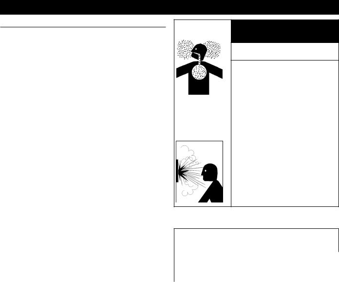
 WARNING
Breathing Hazard
This gas water heater requires an adequate source of clean air for combustion and ventilation. Without sufficient air, your water heater may not operate properly and may emit excessive and abnormal amounts of carbon monoxide which may result in carbon monoxide poisoning or death.
Breathing carbon monoxide can cause brain damage or death. Always read and understand the instruction manual.
The guidelines in this section apply to installations within the United States.All U.S. installations must conform to the
National Fuel Gas Code, ANSI Z223.1/NFPA 54 (current edition) and local codes.
Canadian requirements differ from the guidelines in this section. In Canada, follow the requirements of B149.1
(Natural Gas and Propane Installation Code, current edition) as well as local and provincial codes. Contact your local code enforcement agency for direction.
Check for Chemicals
Air for combustion and ventilation must be clean and free of corrosive chemicals. If corrosive chemicals, such as sulfur, flourine, or chlorine are present, the water heater must be direct vented. Failure of the water heater due to these corrosive chemicals is not covered by the warranty.
WARNING!: In all cases, ensure that corrosive chemicals are not present at the air intake. Presence of such chemicals at the air intake could result in death, personal injury, or property damage. Examples of locations that require outside air due to chemicals include:
•Beauty salons
•Photo processing labs
•Indoor pools
•Laundry, hobby, or craft rooms
•Chemical storage areas
Products such as aerosol sprays, detergents, bleaches, cleaning solvents, gasoline, air fresheners, paint and varnish removers, and refrigerants should not be stored or used near the water heater.
Does your installation space have sufficient combustion air?
Ventilation with outside air is recommended for all installations. Even if the water heater is installed in a large, open room inside the house, outdoor air is usually needed because modern homes are very tightly sealed and often do not supply enough air to the water heater. However, when installed in a large indoor space, it may be possible to provide enough air without outside ventilation. If you are unsure if your installation location has enough ventilation, contact your local gas utility company or code officials for a safety inspection or direct vent the water heater
The following instructions will help determine if it may be possible to install the water heater without outside ventilation.
Calculate Total BTU/h Rating of All Appliances
To calculate the combustion air and ventilation required, add up the total BTU/h ratings of all gas burning appliances (e.g., water heaters, furnaces, clothes dryers) in the same area. Do not include appliances that are direct vented. Refer to the following example.
Your water heater’s BTU/h rating is on the rating plate. The BTU/h ratings should be on the other appliances’ rating plates. If you have trouble determining the BTU/h ratings, contact the manufacturer or have a qualified person determine the ventilation requirements.
NOTICE: If you are replacing your old water heater with one that has a higher BTU/h rating, the amount of ventilation required may be greater.
18

Example:
Gas Burning Appliance |
BTU/h Rating |
|
|
Gas Water Heater |
199,000 |
Furnace |
75,000 |
|
|
Dryer |
20,000 |
|
|
|
|
|
|
Total 294,000
Worksheet for Your Appliances:
Gas Burning Appliance |
BTU/h Rating |
Gas Water Heater
Total
Calculate the Air Volume of the Room
Air requirements depend on the size of the room. Room Volume (ft3) = Floor Area (ft2) X Ceiling Height (ft)
If there are large objects in the room (e.g., refrigerator, furnace, car), subtract their volume from the volume of the room to get a better estimate of the air available.
Air Volume = Room Volume - Object Volume
NOTE: Adjoining rooms with permanently opened doorways can be counted as part of the calculation.
Calculate Required Air Volume
A water heater installed in an unconfined attic, garage, or space requires that the space be at least 50 ft3 (1.42 m3) per 1,000 BTU/h of the total input for all gas burning appliances in the same area.
Required Air Volume (ft3) =Total Appliance Energy Rating (btu/h) X 50 ft3 / 1000 (btu/h)
Example:
(294,000 / 1000) x 50 = 14,700 ft3
If the air volume of the room is less than the required air volume, you must direct vent the water heater or provide permanent outside air openings that draw in sufficient air.
See Install with Outside Ventilation (page 19) if you want to provide combustion air with outside ventilation.
If the air volume of the room is greater than the required air volume, it may be possible to install the water heater without outside ventilation. However, be sure to consider the effects of exhaust fans.
Exhaust fans can affect the amount of combustion air that is available in your home. Appliances such as furnaces, whole house fans, and clothes dryers draw air out of your home. If they draw air out faster than it can be replaced, your water heater may not have enough oxygen to fire properly. Back-drafting may also result, which is when negative air
pressure pulls air backwards through chimneys or appliance vents. These events can cause unsatisfactory water heater performance. The best solution is to direct vent the water heater or install an adequate number of make-up air vents.
See Install with Outside Ventilation (page 19). For more information, consult a qualified technician or your local gas utility.
Install with Outside Ventilation
Ventilation with outside air is recommended, and, for most installations, is needed. There may be existing ventilation that is adequate, or you may need to add more ventilation.
Supplying outside air to the water heater typically requires two openings. One opening must be within 12 in (305 mm) from the floor and the second opening must be within 12 in (305 mm) from the ceiling. Although a single opening is not preferred, you may use a single opening to outside air if the minimum free area is sized according to Table 6. Two openings must be used when ventilating with air from another room.
The outside air can be taken from a crawl space or attic open to the outdoors and adequately ventilated. You may use vertical or horizontal ducts.
Determine Type of Ventilation
There are several types of ventilation that can be used. The following are the various ventilation options.
1.Direct to outdoors
2.Vertical ducts
3.Horizontal ducts
4.Single opening (not recommended; must be at least 100 in2 (6.5 cm2) . Not appropriate for confined spaces smaller than 50 ft3 (1.42 m3) per 1,000 BTU/h or when getting air from another room.)
5.From a larger room inside the house (not recommended
– refer to "Calculate the air volume of the room" above to determine if the combined volume of the rooms may be adequate).
See also the illustrations on the next page.
Determine Minimum Free Area Required for Each Vent Opening
The size of the vent openings depends on the total BTU/h rating of all appliances in the space (use your calculation from “Before beginning”) and the type of vent used. Table 6 provides the minimum free area for each vent opening depending on the type of ventilation.
Calculate Minimum Size of Vent Openings and Ducts
The vent cross-sectional area needed to provide the free area depends on the covering on the vent openings. Typical vents use louvers or grilles to protect the opening. The louver or grill itself blocks some of the free area, so the opening may need to be larger to meet the minimum free area requirements.
19
Use the following formula to calculate the required crosssectional area:
Cross-sectional area = minimum free area required ÷ percent free area of covering (in decimals – e.g., 60 % = 0.6)
For example, an installation area that requires openings with 100 in2 (645 cm2) of free area would need 134 in2 (865 cm2) openings if using metal louvers rated at 75% free area (100 in2 ÷ 0.75 = 134 in2).
If you do not know the % free area for your louver or grill, use the following values:
•For wood louvers or grilles: 25%
•For metal louvers or grilles: 75%
Follow these rules to ensure that vents and ducts provide adequate air flow:
•Each vent opening must be no smaller than 100 in2 (645 cm2).
•Ducts must have the same cross-sectional area as free area of the opening.
•Rectangular ducts must have a minimum dimension of no less than 3 in (76 mm).
•All screens must have mesh ¼” or larger.
•Moveable louvers must be locked open or interconnected with the equipment so that they open automatically during operation.
•Keep louvers and grills clean and free of debris or other obstructions.
Check that Air Source is Clean and Free of Chemicals
Air for combustion and ventilation must be clean and free of corrosive or flammable chemicals. A failure due to corrosive chemicals in the air is not covered by the warranty. Combustion air must be free of acid-forming chemicals such as sulfur, fluorine, and chlorine. Be sure that air at the vent inlets is free of such chemicals.
Table 6 shows the minimum free area of permanent openings for ventilation and combustion air supply with air from outdoor or indoor spaces. The values are based on the total BTU/h input rating for all gas burning appliances within a confined space.
Table 6. Minimum Free Area by Ventilation Type
Opening Source |
Minimum Free Area |
Direct to outdoors* |
1 in2 (6.5 cm2) per 4,000 BTU/hr (See |
|
Figure 8 and Figure 9.) |
Vertical ducts |
1 in2 (6.5 cm2) per 4,000 BTU/hr (See |
|
Figure 13.) |
Horizontal ducts |
1 in2 (6.5 cm2) per 2,000 BTU/hr (See |
|
Figure 10.) |
Single Opening |
1 in2 (6.5 cm2) per 3,000 BTU/hr (See |
|
Figure 11.) |
Two permanent |
1 in2 (6.5 cm2) per 1,000 Btu/hr (See |
openings |
Figure 12.) |
to another room** |
Opening: 100 in2 (645 cm2) MIn |
|
Minimum dimension of air openings: |
|
no less than 3 in (76 mm) |
*These openings connect directly with the outdoors through a ventilated attic, a ventilated crawl space, or through an outside wall.
**United States: For direction on combining spaces in different stories within the structure, refer to the current edition of the National Fuel Gas Code ANSI Z223.1/NFPA 54. In Canada, contact your local code enforcement agency for direction.
Combustion Air Supply Options
Figure 8 through Figure 12 illustrate the range of methods available for ensuring adequate combustion air for the water heater.
|
|
|
|
|
|
|
|
|
|
|
Gable vent |
|||||||
|
|
|
|
|
|
|
|
|
|
|
to outdoors |
|||||||
|
|
|
|
|
|
|
|
|
|
|
|
Install above |
||||||
|
|
|
|
|
|
|
|
|
|
|
|
|||||||
|
|
|
|
|
|
|
|
|
||||||||||
|
|
|
|
|
|
|
|
|
|
|
|
insulation |
||||||
|
|
|
|
|
|
|
|
|
|
|
|
|
|
|
|
|
|
|
|
|
|
|
|
|
|
|
|
|
|
|
|
|
|
|
|
|
|
|
Confined |
|
|
|
|
|
|
|
|
Outlet air to |
|
|
||||||
|
|
|
|
|
|
|
|
|
attic1in2 (6.5cm2) |
|
|
|||||||
|
Space |
|
|
|
|
|
|
|
|
|
|
|||||||
|
|
|
|
|
|
|
|
|
per 4,000 btu/h |
|
|
|||||||
|
|
|
|
|
|
|
|
|
|
|
|
|
|
|||||
|
Alternate |
|
|
|
|
|
|
|
|
Inlet air from |
|
|
||||||
|
Air Inlet |
|
|
|
|
|
|
|
|
|
|
|||||||
|
|
|
|
|
|
|
|
|
|
|
|
the crawl space |
|
|
||||
|
|
|
|
|
|
|
|
|
|
|
|
|
|
|||||
|
|
|
|
|
|
|
|
|
|
|
|
|
|
|
|
|
|
|
|
|
|
|
|
|
|
|
|
|
|
|
|
|
|
|
|
|
|
|
|
|
|
|
|
|
|
|
|
|
|
|
|
|
|
|
|
|
|
|
|
|
|
|
|
|
|
|
|
|
|
|
|
|
|
|
|
|
|
|
|
|
|
|
|
|
|
|
|
|
|
|
|
|
|
|
|
1 in2 (6.5 |
cm2) |
|
|
|
|
|
|
Open |
|
foundation vent |
|||||||
|
|
|
|
|
|
|
|
|||||||||||
|
per 4,000 btu/h |
|
|
|
|
|
|
|
|
|||||||||
|
|
|
|
|
|
|
|
|
||||||||||
Figure 8. Air from Outdoors Openings
|
|
|
12” (305 mm) |
Confined |
|
|
|
|
|
|
|
|
|
||
Two permanent |
|
|
maximum |
Space |
|
|
|
|
|
|
|
|
|
|
|
Openings |
|
|
|
|
|
|
|
1 in2 (6.5 cm2) |
|
|
|
|
|
|
|
per 4,000 btu/h |
|
|
12” (305 mm) |
|
|
|
|
|
|
|
|
|
|
|
|
|
|
|
maximum |
|
|
|
|
|
|
|
|
|
|
|
|
|
|
|
|
|
|
|
|
|
|
|
|
|
|
|
|
Figure 9. Outdoor Air Through Two Openings
20
|
|
|
|
|
|
|
|
|
|
|
|
|
|
Gable vent |
||
|
|
|
|
|
|
|
|
|
|
|
|
|
|
to outdoors |
||
|
|
|
|
|
|
|
|
|
|
|
|
|
|
Install above |
||
|
|
|
|
|
|
|
|
|
|
|
|
|
|
|||
|
|
|
|
|
|
|
|
|
|
|
|
|
|
|||
|
|
|
|
|
|
|
|
|
|
|
|
|
|
insulation |
||
|
|
|
|
|
|
|
|
|
||||||||
|
|
|
|
|
|
|
|
|
||||||||
|
|
|
|
|
|
|
|
|
|
|
|
|
|
|
|
|
|
|
|
|
|
|
|
|
|
|
|
|
|
|
|
|
|
|
|
|
|
|
|
|
|
|
|
|
|
|
|
|
Outlet air to |
|
|
|
|
|
|
|
|
|
|
|
|
|
|
|
|
attic 1 in2(6.5cm2) |
|
|
Confined |
|
|
|
|
|
|
|
|
|
|
|
|
|
per 4,000 btu/h |
|
|
Space |
|
|
|
|
|
|
|
|
|
|
|
|
|
Inlet air duct |
|
|
|
|
|
|
|
|
|
|
|
|
|
|
|
|
|
|
|
|
|
|
|
|
|
|
|
|
|
|
|
|
|
1 in2 (6.5cm2) |
|
|
|
12”(305mm) |
|
|
|
|
|
|
|
|
per 4,000 btu/h |
|
||||
|
|
|
|
|
|
|
|
|
|
|||||||
|
|
|
|
|
|
|
|
|
|
|||||||
|
|
maximum |
|
|
|
|
|
|||||||||
|
|
|
|
|
|
|||||||||||
|
|
|
|
|
|
|
|
|
|
|
|
|
|
|
|
|
|
|
|
|
|
|
|
|
|
|
|
|
|
|
|
|
|
Figure 10. Vertical Duct Openings
1 in2 (6.5 cm2) per 2,000 btu/h
Outlet
Confined
Space 
 Outdoor
Air Ducts
Inlet
1 in2 (6.5 cm2) per 2,000 btu/h
Figure 11. Horizontal Duct Openings
Alternative
Opening
Location
Confined
Space  1 in2 (6.5 cm2) per 3,000 btu/h
Figure 12. Outdoor Air Through One Opening
12” (305 mm) |
|
|
maximum |
|
|
Confined |
Two permanent |
1 in2 per |
Space |
Openings |
1,000 btu/h |
|
12” (305 mm) maximum |
|
Figure 13. Indoor Air Through Two Permanent Openings MAXIMUM EQUIVALENT PIPE LENGTHS AND ELBOWS
The maximum length of exhaust vent piping must not exceed 70 ft (21.3 m) for 3” venting, which depends on the elevation where the water heater is installed, and 100 ft (30.5 m) for 4” venting (deducting 5 ft (1.5 m) for each elbow used in the venting system). Do not use more than 5 elbows. See Table 7.
When the horizontal vent run exceeds 5 ft (1.5 m), support the vent run at 3 ft (0.9 m) intervals with overhead hangers.
Table 7. Equivalent Lengths and Maximum Number of Elbows
|
|
3" (76 mm) Venting |
4" (102 mm) |
|
No. of |
|
Venting |
||
|
|
|
||
|
|
|
|
|
Elbows |
|
|
|
|
|
0 to 3,000 ft |
3,001 to 6,000 ft |
6,001 to 10,100 ft |
0 to 10,100 ft |
|
(0 to 914 m) |
(915 to 1,829 m) |
(1,830 to 3,078 m) |
(0 to 3,078 m) |
0 |
70 ft (21.3 m) |
40 ft (12.2 m) |
25 ft (7.6 m) |
100 ft (30.5 m) |
1 |
65 ft (19.8 m) |
35 ft (10.7 m) |
20 ft (6.1 m) |
95 ft (29.0 m) |
2 |
60 ft (18.3 m) |
30 ft (9.1 m) |
15 ft (4.6 m) |
90 ft (27.4 m) |
3 |
55 ft (16.8 m) |
25 ft (7.6 m) |
10 ft (3.0 m) |
85 ft (25.9 m) |
4 |
50 ft (15.2 m) |
20 ft (6.1 m) |
N/A |
80 ft (24.4 m) |
5 |
45 ft (13.7 m) |
N/A |
N/A |
75 ft (22.9 m) |
Excludes vent terminators, termination elbows, or rain caps.
Diameter |
Max. No. of Max. Vertical and Horizontal |
||
Elbows |
(Total) Vent Length |
||
|
|||
3 in. (76 mm) |
5 |
70 ft (21.3 m) |
|
4 in. (102 |
5 |
100 ft (30.5 m) |
|
mm) |
|||
|
|
||
*For each elbow added, deduct 5 ft. (1.5 m) from max. vent length.
21
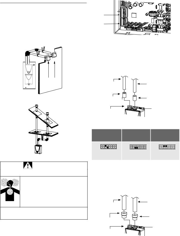
DIRECT VENT INSTALLATIONS
TWO-PIPE, DIRECT-VENT INSTALLATION
For details of the optional items, refer to the Installation manual for each optional item.
HOW TO INSTALL A TWO-PIPE, DIRECT-VENT SYSTEM
Install as shown in the following figures. See Clearances For Rooftop Terminations (page 36) for the proper clearances.
Hanger

 Wall
Wall
Hanger
Sidewall Vent
Terminations
Figure 14. Two-Pipe Horizontal Installation
Upper DIP
Switch
Bank
Lower DIP
Switch Bank
Figure 16. Location of DIP Switches Installing a Three-Inch (76 mm) Direct Vent Connection
1.Connect 3" (76 mm) couplings directly on the exhaust and intake vent collar of the water heater.
2.Connect 3" (76 mm) straight pipes to the couplings.
3.Locate lower bank of DIP switches and set the appropriate switches for this configuration. See the appropriate settings below.
3"(76 mm) |
3" (76 mm) |
|
straight pipe |
straight pipe |
|
3" (76 mm) coupling |
3" (76 mm) coupling |
|
(included) |
||
(included) |
||
|
||
|
Exhaust vent collar |
|
Intake vent collar |
(Female) |
|
(Female) |
|
Figure 17. 3" (76 mm) Vent Connection
Table 8. DIP Switch Settings: Three-Inch Direct Vent
5 to 20 ft |
21 to 40 ft |
41 to 70 ft |
(1.5 to 6.1m) |
(6.2 to 12.2 m) |
(12.3 to 21.3 m) |
(DEFAULT) |
ON 1 2 3 4 5 6 7 8 |
ON 1 2 3 4 5 6 7 8 |
ON 1 2 3 4 5 6 7 8 |
OFF |
OFF |
OFF |
Figure 15. Two-Pipe Vertical Installation |
No. 3 : O N |
No. 3 : OFF |
No. 3 : O N |
No. 4 : OFF |
No. 4 : OFF |
No. 4 : O N |
WARNING |
1. Connect 3"x 4" (76 x 102 mm) adaptors directly on the |
|
Installing a Four-Inch (102 mm) Direct Vent Connection |
|
|
|
|
Breathing Hazard |
exhaust and intake vent collar of the water heater. |
•Adjust the appropriate DIP switches according to 2. Connect 4" (102 mm) straight pipes to the adaptors.
model and vent length as shown. DO NOT adjust |
3. Locate lower bank of DIP switches and set the |
|
the other DIP switches. |
appropriate switches for this configuration. See the |
|
• Turn off the power supply to the water heater |
appropriate settings below. |
|
before changing the DIP switch settings. |
|
|
• Failure to observe these warnings could lead to |
|
4" (102 mm) |
carbon monoxide poisoning or death. |
|
|
|
4" (102 mm) |
straight pipe |
Breathing carbon monoxide can cause brain damage |
straight pipe |
|
|
|
|
or death. Always read and understand the instruction |
|
3"x 4" |
manual. |
3"x 4" |
(76 x 102 mm) |
|
adaptor |
|
|
(76 x 102 mm) |
|
|
adaptor |
Exhaust vent collar |
|
Intake vent collar |
(Female) |
|
|
|
|
(Female) |
|
|
Figure 18. Four-Inch (102 mm) Two-Pipe Vent Connection |
|
22
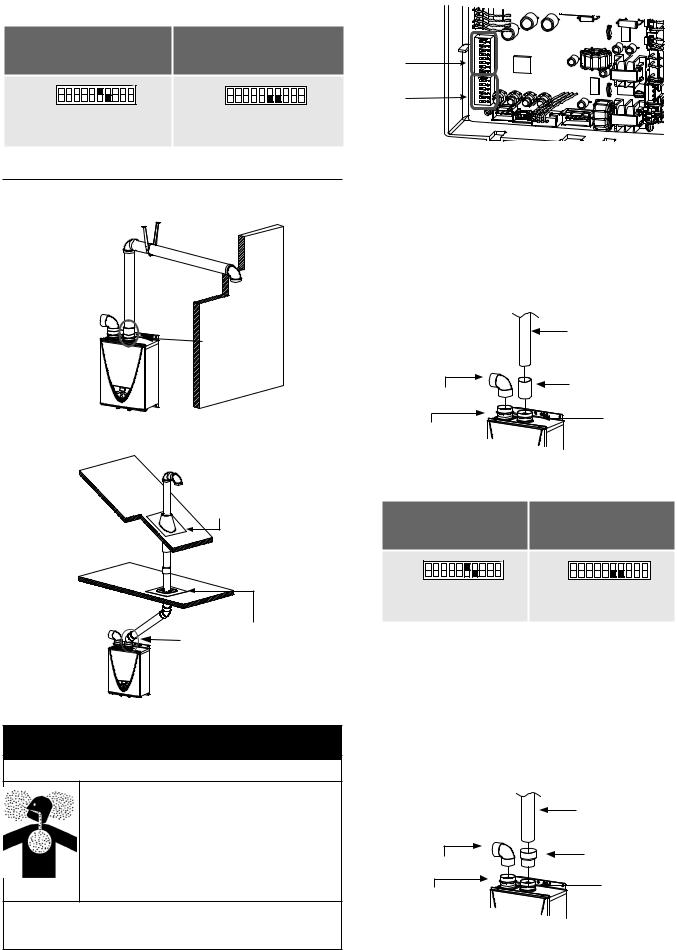
Table 9. DIP Switch Settings: Four-Inch Direct Vent
5 to 50 ft |
51 to 100 ft |
|
(1.5 to 15.2m) |
||
(15.3 to 30.5 m) |
||
(DEFAULT) |
||
|
ON 1 2 3 4 5 6 7 8 9 10 |
ON 1 2 3 4 5 6 7 8 9 10 |
OFF |
OFF |
No. 6 : O N |
No. 6 : OFF |
No. 7 : OFF |
No. 7 : OFF |
SINGLE-VENT INSTALLATIONS
HOW TO INSTALL A SINGLE-PIPE WITH ROOM-AIR INTAKE INSTALLATION
Hanger |
Wall |
|
Elbow |
Connect between |
|
exhaust vent |
|
collar and piping. |
Figure 19. Single-Pipe Horizontal Installation
Roof
Roof Flashing
Elbow |
Fire Stop |
|
Connect between |
||
|
||
|
exhaust vent collar |
|
|
and piping. |
Figure 20. Single-Pipe Vertical Installation
 WARNING
Breathing Hazard
•Adjust the appropriate DIP switches according to model and vent length as shown below. DO NOT adjust the other DIP switches.
•Turn off the power supply to the water heater before changing the DIP switch settings.
•Failure to observe these warnings could lead to carbon monoxide poisoning or death.
Breathing carbon monoxide can cause brain damage or death. Always read and understand the instruction manual.
Upper DIP
Switch
Bank
Lower DIP
Switch Bank
Figure 21. Location of DIP Switches How to Install a Three-Inch Single-Vent Installation
1.Connect a 3" (76 mm) elbow directly on the intake vent collar of the water heater.
2.Connect a 3" (76 mm) coupling directly on the exhaust vent collar of the water heater.
3.Connect a 3" (76 mm) straight pipe to the coupling.
4.Locate lower bank of DIP switches and set the appropriate switches for this configuration. See the appropriate settings below.
|
3"(76 mm) |
|
straight pipe |
|
3" (76 mm) coupling |
3” (76 mm) elbow |
(included) |
with bird screen |
Exhaust vent |
|
|
Intake vent collar |
collar |
(Female) |
(Female) |
Figure 22. Three-Inch (76 mm) Vent Connection |
||
Table 10. DIP Switch Settings: Three-Inch Single- |
||
Vent Pipe |
||
5 to 45 ft |
46 to70 ft |
|
(1.5 to 13.7m) |
||
(13.8 to 21.3 m) |
||
(DEFAULT) |
||
|
||
ON 1 2 3 4 5 6 7 8 9 10 |
ON 1 2 3 4 5 6 7 8 9 10 |
|
OFF |
OFF |
|
No. 6 : O N |
No. 6 : OFF |
|
No. 7 : OFF |
No. 7 : OFF |
|
How to Install a Four-Inch Single-Vent Installation
1.Connect a 3" (76 mm) elbow directly on the intake vent collar of the water heater.
2.Connect a 3" x 4" (76 x 102 mm) adaptor directly on the exhaust vent collar of the water heater.
3.Connect a 4" (102 mm) straight pipe to the adaptor.
4.Locate lower bank of DIP switches and set the appropriate switches for this configuration. See the appropriate settings below.
|
4" (102 mm) |
|
|
straight pipe |
|
|
3"x 4" |
|
3” (76 mm) elbow |
(76 x 102 mm) |
|
increaser |
||
with bird screen |
||
Exhaust vent |
||
|
||
Intake vent collar |
collar |
|
(Female) |
(Female) |
Figure 23. Four-Inch (102 mm) Vent Connection
23
Loading...