

Page 1
Site Master is the preferred cable and antenna analyzer of
wireless providers, contractors and installers.
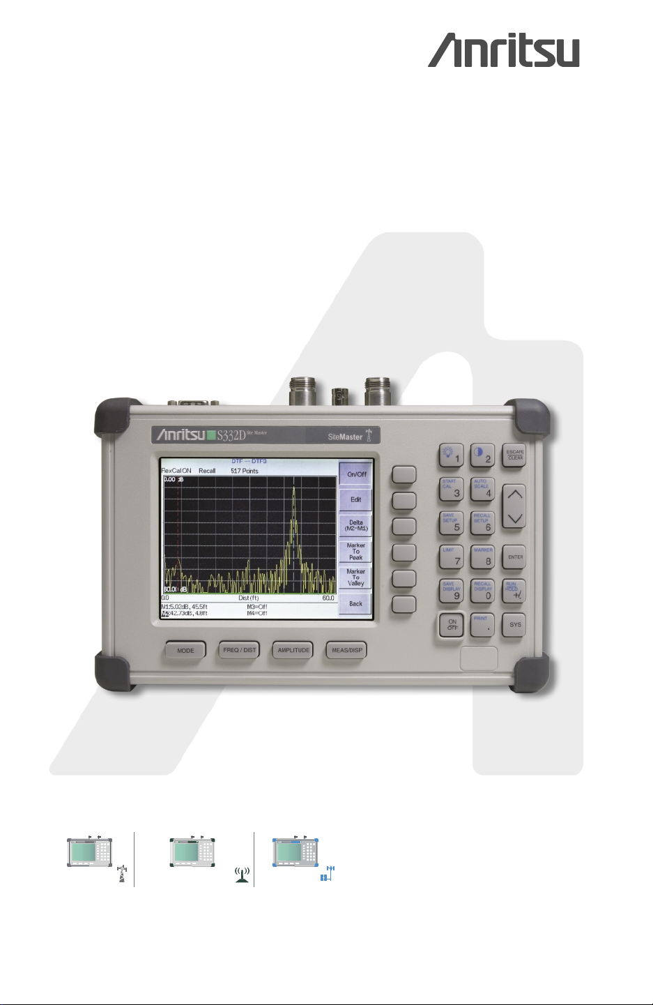
Site Master
™
S331D/S332D
Cable and Antenna Analyzer
MS2712
MS2712
MS2712
SiteMaster
SpectrumMaster
CellMaster
MS2711D
Spectrum Master
S331D
Site Master
SiteMaster
SpectrumMaster
MT8212A
Cell Master
CellMaster
Color display option shown
Programming Manual
Page 2

WARRANTY
The Anritsu product(s) listed on the title page is (are) warranted against defects in materi
als and workmanship for one year from the date of shipment.
Anritsu’s obligation covers repairing or replacing products which prove to be defective
during the warranty period. Buyers shall prepay transportation charges for equipment re
turned to Anritsu for warranty repairs. Obligation is limited to the original purchaser.
Anritsu is not liable for consequential damages.
LIMITATION OF WARRANTY
The foregoing warranty does not apply to Anritsu connectors that have failed due to nor
mal wear. Also, the warranty does not apply to defects resulting from improper or inade
-
quate maintenance by the Buyer, unauthorized modification or misuse, or operation
outside the environmental specifications of the product. No other warranty is expressed or
implied, and the remedies provided herein are the Buyer’s sole and exclusive remedies.
TRADEMARK ACKNOWLEDGEMENTS
Site Master is a trademark of Anritsu Company.
NOTICE
Anritsu Company has prepared this manual for use by Anritsu Company personnel and
customers as a guide for the proper installation, operation, and maintenance of Anritsu
Company equipment and computer programs. The drawings, specifications, and information contained herein are the property of Anritsu Company, and any unauthorized use or
disclosure of these drawings, specifications, and information is prohibited; they shall not
be reproduced, copied, or used in whole or in part as the basis for manufacture or sale of
the equipment or software programs without the prior written consent of Anritsu Company.
-
UPDATES
Updates to this manual, if any, may be downloaded from the Anritsu internet site at:
http://www.us.anritsu.com.
March 2004 10580-00100
Copyright ã 2003-2004 Anritsu Co. Revision: B
Page 3

Table of Contents
Programming Overview . . . . . . . . . . . . . . . . . . . . . . . . . ............1
Control Byte Summary. . . . . . . . . . . . . . . . . . . . . . ................3
Control Byte Descriptions . . . . . . . . . . . . . . . . . . . . ................7
Setup System – Control Byte #1 (01h) ....................................7
Set Site Master VNA Frequency – Control Byte #2 (02h) ..........................7
Select Measurement Mode – Control Byte #3 (03h) .............................8
Set Site Master VNA Scale – Control Byte #4 (04h) .............................8
Set Site Master VNA Marker – Control Byte #5 (05h)............................9
Set Site Master VNA Single Limit – Control Byte #6 (06h) .........................9
Set DTF Parameter – Control Byte #7 (07h) ................................10
Set Time/Date – Control Byte #8 (08h) ...................................11
Set Reference Number – Control Byte #9 (09h) ..............................11
Serial Port Echo On/Off – Control Byte #10 (0Ah) .............................11
Site Master VNA Single Sweep Mode On/Off – Control Byte #11 (0Bh) .................12
Watch-Dog Timer On/Off – Control Byte #12 (0Ch) ............................12
Sequence Site Master Calibration – Control Byte #13 (0Dh) ........................13
Set Site Master Data Points – Control Byte #14 (0Eh) ...........................13
Set Site Master Calibration Mode – Control Byte #15 (0Fh) ........................13
Store Sweep Trace – Control Byte #16 (10h) ................................14
Recall Sweep Trace – Control Byte #17 (11h) ...............................14
Save System Setup – Control Byte #18 (12h) ................................20
Recall System Setup – Control Byte #19 (13h) ...............................21
Query System Status – Control Byte #20 (14h) ...............................21
Trigger Self-Test – Control Byte #21 (15h) .................................28
Read Fail Counter – Control Byte #22 (16h) ................................29
Query Trace Names – Control Byte #24 (18h) ...............................29
Delete Sweep Trace – Control Byte #25 (19h) ...............................29
Upload SPA Sweep Trace – Control Byte #26 (1Ah) ............................30
Query Sweep Memory – Control Byte #27 (1Bh)..............................33
Upload Site Master VNA Sweep Trace – Control Byte #28 (1Ch) .....................33
Query System Status – Control Byte #29 (1Dh) ..............................36
Select Printer Type – Control Byte #30 (1Eh)................................48
Select DTF Windowing – Control Byte #31 (1Fh) .............................49
Set Site Master VNA Trace Math – Control Byte #32 (20h) ........................49
Recall Sweep Trace – Control Byte #33 (21h) ...............................49
Set Site Master VNA Trace Overlay – Control Byte #34 (22h) ......................61
Set SPA A/B Trace – Control Byte #35 (23h) ...............................61
Site Master PM i
Page 4

Upload Sweep Trace – Control Byte #36 (24h) ..............................62
Get Options – Control Byte #37 (25h) ...................................71
Query Power Level – Control Byte #39 (27h) (Option 29 only) ......................72
Set Power Meter Units – Control Byte #40 (28h) (Option 29 only) ....................72
Power Meter Relative Mode On/Off – Control Byte #41 (29h) (Option 29 only) .............73
Power Meter Offset Mode On/Off – Control Byte #42 (2Ah) (Option 29 only) ..............73
Power Meter Zero Mode On/Off – Control Byte #43 (2Bh) (Option 29 only) ...............73
Power Meter RMS Averaging On/Off – Control Byte #44 (2Ch) (Option 29 only) ............73
Power Meter Center Freq and Span Setup – Control Byte #45 (2Dh) (Option 29 only) ..........74
Trigger Sweep – Control Byte #48 (30h) ..................................74
Trigger Sweep – Control Word (AA30h) ..................................74
Check Battery Status – Control Byte #50 (32h) ...............................74
Set SPA Minimum Sweep Time - Control Byte #53 (35h) .........................75
Set Trigger Position - Control Byte #54 (36h) ...............................75
Set Video Trigger Level - Control Byte #55 (37h) .............................75
Automatically Save Runtime Setup – Control Byte #64 (40h) .......................76
Enter Remote Mode – Control Byte #69 (45h) ...............................76
Enter Remote Mode Immediately – Control Byte #70 (46h) ........................76
Write Custom Cable – Control Byte #80 (50h) ...............................77
Recall Custom Cable – Control Byte #81 (51h)...............................77
Write Antenna – Control Byte #82 (52h) ..................................78
Recall Antenna – Control Byte #83 (53h) .................................78
Set Field Strength Measurement – Control Byte #84 (54h) .........................79
Set Channel Power – Control Byte #85 (55h) ................................79
Read Channel Power – Control Byte #86 (56h) ...............................80
Set Adjacent Channel Power Ratio (ACPR) – Control Byte #87 (57h)...................80
Read Adjacent Channel Power Ratio (ACPR) – Control Byte #88 (58h)..................80
Read Signal Standard Name – Control Byte #89 (59h) ...........................81
Measure OCC BW % of Power – Control Byte #96 (60h) .........................81
Measure OCC BW dB Down – Control Byte #97 (61h) ..........................82
Set Bias Tee Function - Control Byte #98 (62h) (Option 10 only) .....................82
Set Spectrum Analyzer Start/Stop Frequency – Control Byte #99 (63h) ..................83
Set Spectrum Analyzer Center Freq./Span – Control Byte #100 (64h) ...................83
Set Spectrum Analyzer Scale – Control Byte #101 (65h) ..........................83
Set Spectrum Analyzer Marker – Control Byte #102 (66h).........................84
Set Spectrum Analyzer Single Limit – Control Byte #103 (67h) ......................84
Set Spectrum Analyzer Peak Hold – Control Byte #105 (69h) .......................85
Set Spectrum Analyzer Resolution Bandwidth – Control Byte #106 (6Ah) ................85
Set Spectrum Analyzer Video Bandwidth – Control Byte #107 (6Bh) ...................85
Set Spectrum Analyzer Sweep Mode – Control Byte #108 (6Ch) .....................86
ii Site Master PM
Page 5

Set Spectrum Analyzer Marker to Peak – Control Byte #109 (6Dh) ....................86
Set Spectrum Analyzer Marker to Center – Control Byte #110 (6Eh) ...................86
Set Spectrum Analyzer Attenuation – Control Byte #111 (6Fh) ......................87
Set Site Master VNA Segmented Limit Lines – Control Byte #112 (70h) .................87
Set Spectrum Analyzer Multiple Limit – Control Byte #113 (71h) ....................88
Set Return Spectrum Analyzer Sweep Time – Control Byte #114 (72h) ..................89
Set Reference Level Offset – Control Byte #115 (73h) ...........................89
Read Marker Value – Control Byte #117 (75h) ...............................90
Set Sweep Averaging – Control Byte #118 (76h) ..............................90
Field InstaCal – Control Byte #120 (78h) ..................................90
Read InstaCal Module ASCII Serial Number – Control Byte #124 (7Ch) .................91
Set Site Master Marker (Peak/Valley) – Control Byte #129 (81h) .....................91
Set / Reset Spectrum Analyzer External Reference – Control Byte #133 (85h) ..............91
Check Spectrum Analyzer External Reference – Control Byte #134 (86h).................92
Set SPA Preamp State (On/Off/Auto) – Control Byte #136 (88h) .....................92
Set Spectrum Analyzer Units – Control Byte #140 (8Ch) .........................92
Set Spectrum Analyzer Resolution Bandwidth – Control Byte #141 (8Dh) ................93
Set Spectrum Analyzer Video Bandwidth – Control Byte #142 (8Eh) ...................93
Set Spectrum Analyzer Attenuation – Control Byte #143 (8Fh) ......................93
Set AM/FM Demodulation – Control Byte #145 (91h) ...........................94
Set Baud Rate – Control Byte #197 (C5h) .................................95
Set Language – Control Byte #198 (C6h) ..................................95
Query Time – Control Byte #208 (D0h) ..................................95
Read ASCII Serial Number – Control Byte #225 (E1h) ..........................96
Exit Remote Mode – Control Byte #255 (FFh) ...............................96
Set T1 Transmission Level – Control Word (A001h) (Option 50 only) ..................96
Set T1/E1 Clock Source – Control Word (A002h) (Option 50 only) ....................96
Set T1/E1 Pattern – Control Word (A003h) (Option 50 only) .......................97
Set T1/E1 Error Insert Type/Value – Control Word (A004h) (Option 50 only) ..............97
Set T1/E1 Framing Mode – Control Word (A005h) (Option 50 only) ...................98
Start and Stop T1/E1 Measurement – Control Word (A006h) (Option 50 only) ..............98
Insert Error for T1/E1 Measurement – Control Word (A007h) (Option 50 only)..............98
Get T1/E1 Pattern – Control Word (A008h) (Option 50 only) .......................98
Get T1/E1 Frame Sync Status – Control Word (A009h) (Option 50 only) .................99
Get T1/E1 Pattern Sync Status – Control Word (A00Ah) (Option 50 only) ................99
Get T1/E1 Carrier Status – Control Word (A00Bh) (Option 50 only) ...................99
Get T1/E1 Error Type and Number – Control Word (A00Ch) (Option 50 only) ..............99
Set T1/E1 Line Coding Options – Control Word (A00Dh) (Option 50 only) ...............100
Set E1 Impedance Options – Control Word (A00Eh) (Option 50 only) ..................100
Read T1/E1 Volts Peak-to-Peak – Control Word (A00Fh) (Option 50 only) ...............100
Site Master PM iii
Page 6

Set T1/E1 Receive Input Configuration Options - Control Word (A013h) (Option 50 only) .......101
Set T1/E1 Measurement Duration - Control Word (A014h) (Option 50 only) ..............101
Set T1/E1 Data Logging - Control Word (A015h) (Option 50 only) ...................101
Read T1/E1 dBdsx - Control Word (A016h) (Option 50 only) ......................102
Read T1/E1 Frequency - Control Word (A017h) (Option 50 only) ....................102
Read T1/E1 Frequency Cal - Control Word (A018h) (Option 50 only) ..................102
Set T1/E1 Frequency Cal - Control Word (A019h) (Option 50 only) ...................102
Select SPA/Power Meter Signal Standard - Control Word (A103h)....................103
Select SPA/Power Meter Channel - Control Word (A104h)........................103
Read External Module Name – Control Word (A201h) (Option 6 only) .................103
Read External Module Serial Number – Control Word (A202h) (Option 6 only).............104
Read External Module Frequency Range – Control Word (A203h) (Option 6 only) ...........104
Read Module Fail Counter – Control Word (A204h) (Option 6 only)...................104
Clear Module Fail Counter – Control Word (A205h) (Option 6 only) ..................105
Remote Self Test - Control Word (AA15h) ................................105
Programming Examples. . . . . . . . . . . . . . . . . . . . . . . . . . . . . . . .....108
Examples in C ...............................................108
Example in Visual Basic ..........................................117
Parameter Definitions .....................................119
Spectrum Analyzer Signal Standards . . . . . . . . . . . . . . . .............120
VNA Signal Standards.....................................123
iv Site Master PM
Page 7

Programming Overview
NOTE: This programming manual is written exclusively for Anritsu Site Master Models S331D and
S332D. For information on firmware upgrades, contact your local Anritsu Service Center. Commands
listed in this manual are not all backward-compatible with earlier Anritsu models.
General Description
The Site Master must first be set into “remote” mode for communication with a computer. Remote mode differs from normal
repetitive sweep and single-sweep modes. During remote mode, the Site Master suspends normal operations and attends to
the serial port. The front panel display indicates when the Site Master is in remote mode.
Once in remote mode, a series of control bytes and associated data are sent to the Site Master to perform various functions
and activities. The serial port supports virtually all features accessible from the keypad with the exception of the printer. The
printer requires connection to the same 9-pin connector on the Site Master rear panel used for remote communication.
To complete the communication session, send the control byte to exit remote mode and the Site Master will resume normal
operations. You may also exit the remote mode by pressing the ESCAPE/CLEAR key on the Site Master front panel.
Interface Cable Installation
The Site Master is a DTE-type serial device. Communication between the Site Master and a PC is accomplished over a null
modem serial cable provided with the Site Master (Anritsu part number 800-441). Connect the cable to the Serial Interface
connector on the Site Master test connector panel and to the appropriate COM port connector on the PC.
Serial Communication Parameters
The Site Master begins communication at 9600 bps when first powered on. It uses no parity bits, 8 data bits, and 1 stop bit
(N-8-1). No hardware handshaking is used. The Set Baud Rate Control Byte #197 (C5h) serial command can be used to
change the baud rate to 19,200, 38,400, 56,000 or 115,200. An invalid setting returns the rate to 9600.
Communications Error Checking
Since there is no hardware handshaking, byte level error handling must be done by the controlling program. Use the expected
number of response bytes (listed in the control byte description section of this manual) when waiting for feedback from the
Site Master. For data streams going to the Site Master, the “watch dog timer” protects against interrupted transmissions by
aborting a control byte sequence if the inter-byte time limit is exceeded.
Parameter Validation
The Site Master validates input parameters for each control byte sequence. If the input parameters are out of range or invalid,
the Site Master notifies the computer by sending Parameter Error Byte #224 (E0h). The Site Master discards the received
data and waits for the next control byte.
Entering Remote Mode
Send the Enter Remote Mode Byte #69 (45h) to the Site Master to enter remote mode at the end of the current sweep. Send
the Enter Remote Mode Immediately byte #70 (46h) to enter remote mode in the middle of a sweep.
The Site Master serial port buffer is one byte wide. No internal buffer exists, so waiting for the response from the unit is es
sential. If the Site Master is not in remote mode, sending a second byte overwrites the original byte commanding it to enter
remote mode. If control byte #69 is sent, the Site Master will enter remote mode at the end of the current sweep. If control
byte #70 is sent, the unit will enter remote mode as soon as it receives the byte. This means that data stored for the current
sweep may be incomplete. Once a response string is received from the Site Master, the unit is ready to accept additional con
trol bytes.
-
-
Site Master PM 1
Page 8

Exiting Remote Mode
To exit remote mode, send the Exit Remote Control byte #255 (FFh) to the Site Master. The Site Master sends a response
byte of 255 (FFh) then exits remote mode. Remote mode can also be exited by pressing the ESCAPE/CLEAR front panel
key.
Remote Mode Changes to Site Master Operating Parameters
System parameters changed during remote mode remain changed for normal operation after the unit exits remote mode.
However, the changes are not automatically written to the non-volatile EEPROM. Turning off the Site Master power erases
the changed settings.
To retain the changes, the setup must be saved to one of the setup memory locations. Use either the run-time setup location 0,
(which holds the power-on defaults) or one of the nine other setup locations. Control byte #64 (40h) sets the auto-save flag
which commands the Site Master to automatically save the changes to the run-time setup location upon exiting remote mode.
See the Site Master User’s Guide or information in this manual on control byte #18 (12h) for further details.
Write Cycle Limitation of EEPROM
The EEPROM, used to store calibrations, setups and traces has a guaranteed lifetime of at least 100,000 write cycles and an
unlimited number of read cycles. The write cycle limitation is for a specific location. For example, setup #1 can be stored
100,000 times and setup #2 can be stored 100,000 times, etc. Because of this, the Site Master does not automatically store the
changed system parameters to the EEPROM. Be aware of the EEPROM write cycle limitation when programming the Site
Master and keep the number of write cycles to a minimum.
Documentation Conventions
Throughout this manual, the following conventions will be observed:
Numeric Representation
Hexadecimal numbers are represented with the suffix h. For example, the decimal number 255 is represented in hexadecimal
as FFh.
Binary numbers are represented with the suffix b. For example, the decimal number 2 is represented in binary as 10b.
Decimal numbers are represented with the prefix # when referring to a control byte (command byte) and without a prefix or
suffix in all other cases.
Bit Positions
When enumerating bits in a byte, bit 0 will always be the least significant bit (LSB).
Mode References
The term “VNA” in reference to a command denotes Return Loss, SWR, Cable Loss and DTF modes. The term “SPA” in
reference to a command denotes Spectrum Analyzer mode. All other modes are referenced individually.
2 Site Master PM
Page 9

Control Byte Summary
Control Byte
#
1 (01h) Setup System Sets system status flags and switches Yes
2 (02h) Set VNA Frequency Sets Site Master VNA frequency range Yes
3 (03h) Select Measurement Mode Sets current Site Master measurement mode Yes
4 (04h) Set VNA Scale Sets Site Master VNA scale values Yes
5 (05h) Set VNA Marker Sets position and on/off status of Site Master markers in VNA modes Yes
6 (06h) Set VNA Single Limit Sets position and on/off status of the Site Master single limit in VNA modes Yes
7 (07h) Set DTF Parameters Sets Distance to Fault parameters Yes
8 (08h) Set Time/Date Sets time and date of the Site Master Yes
9 (09h) Set Reference Number Sets reference number (trace name) for a sweep trace Yes
10 (0Ah) Serial Port Echo On/Off Allows synchronization of Site Master and request from computer for sweep trace Yes
11 (0Bh) VNA Single Sweep On/Off Enables or disables single sweep operation in VNA modes Yes
12 (0Ch) Watch-dog Timer On/Off Enables or disables the watch-dog timer —-
13 (0Dh) Sequence SM Calibration Triggers a calibration step Yes
14 (0Eh) Set Site Master Data Points Sets number of measurement data points for Site Master VNA modes Yes
15 (0Fh) Set SM Calibration Mode Sets the Site Master calibration mode to OSL Cal (standard) or FlexCal Yes
16 (10h) Store Sweep Trace Saves current trace data to EEPROM —-
17 (11h) Recall Sweep Trace Site Master sends the sweep data associated with a trace (obsolete) Yes
18 (12h) Save System Setup Saves system setup parameters to EEPROM Yes
19 (13h) Recall System Setup Recalls system setup parameters from EEPROM Yes
20 (14h) Query System Status Gets the current system settings (obsolete) —-
21 (15h) Trigger Self-Test Triggers a self test —-
22 (16h) Read Fail Counters Returns the values of the lock-fail and integrator counters —-
24 (18h) Query Trace Names Returns list of all saved traces —-
25 (19h) Delete Sweep Trace Deletes single or all stored sweep traces Yes
26 (1Ah) Upload SPA Sweep Trace Uploads a spectrum analyzer sweep trace to Site Master (obsolete) Yes
27 (1Bh) Query Sweep Memory Queries Site Master for percentage of memory that is available for trace storage —-
28 (1Ch) Upload VNA Sweep Trace Uploads a Site Master VNA mode sweep trace to the Site Master (obsolete) Yes
29 (1Dh) Query System Status Queries the Site Master for current system settings Yes
30 (1Eh) Select Printer Type Selects printer type Yes
31 (1Fh) Select DTF Windowing Selects DTF Windowing Methods Yes
32 (20h) Set VNA Trace Math Selects Trace Math operation for VNA modes Yes
33 (21h) Recall Sweep Trace Queries the Site Master for sweep trace data Yes
34 (22h) Set VNA Trace Overlay Sets trace overlay operation and trace for VNA modes Yes
35 (23h) Set SPA A/B Trace Defines traces “A” and “B” for SPA mode Yes
36 (24h) Upload Sweep Trace Uploads a sweep trace to the Site Master Yes
37 (25h) Get Options Returns an ASCII string listing installed options —-
39 (27h) Query Power Level Returns power level at RF In in Power Meter mode —-
40 (28h) Set Power Meter Units Sets Power Meter displaying unit Yes
41 (29h) Power Meter Relative Mode Enables or disables Power Meter Relative Mode Yes
Name Description
Watchdog
Timer
Site Master PM 3
Page 10

Control Byte
#
42 (2Ah) Power Meter Offset Mode Enables or disables Power Meter offset Yes
43 (2Bh) Power Meter Zero Mode Enables or disables Power Meter zeroing mode Yes
44 (2Ch)
45 (2Dh)
48 (30h) Trigger Sweep Starts the next sweep —-
50 (32h) Check Battery Status Returns smart battery status —-
53 (35h)
54 (36h) Set Trigger Position Sets the trigger position for the SPA when the span is 0 Yes
55 (37h) Set Video Trigger Level Sets the trigger level for the SPA in video trigger mode Yes
64 (40h) Auto Save Runtime Setup Automatically save the runtime setup when exiting remote mode Yes
69 (45h) Enter Remote Mode
70 (46h)
80 (50h) Write Custom Cable Writes Custom Cable data to Site Master Yes
81 (51h) Recall Custom Cable Recalls Custom Cable data from Site Master Yes
82 (52h) Write Antenna Writes custom antenna data to the Site Master via the serial port Yes
83 (53h) Recall Antenna Recalls custom antenna data from the Site Master via the serial port Yes
84 (54h)
85 (55h) Set Channel Power Sets the Channel Power measurement state and the setup parameters Yes
86 (56h) Read Channel Power Reads the current channel power or the channel power of a stored trace Yes
87 (57h) Set ACPR Sets the ACPR measurement state and parameters Yes
88 (58h) Read ACPR
89 (59h)
96 (60h)
97 (61h)
98 (62h) Set Bias Tee Function Set the Bias Tee function On/Off (Option 10 only) Yes
99 (63h)
100 (64h)
101 (65h)
102 (66h)
103 (67h)
105 (69h)
Power Meter RMS
Averaging On/Off
Power Meter Center
Frequency and Span
Set SPA Minimum Sweep
Time
Enter Remote Mode
Immediately
Set Field Strength
Measurement
Read Signal Standard
Name
Measure OCC BW % of
Power
Measure OCC BW dB
Down
Set Spectrum Analyzer
Start/Stop Frequency
Set Spectrum Analyzer
Center Freq./Span
Set Spectrum Analyzer
Scale
Set Spectrum Analyzer
Marker
Set Spectrum Analyzer
Single Limit
Set Spectrum Analyzer Max
Hold
Name Description
Sets Power Meter RMS Averaging. Yes
Sets the center frequency and span frequency for the Power Meter mode Yes
Sets the min sweep time for the SPA when the span is 0 Yes
Enters remote mode at the end of the sweep and returns model number and
firmware version
Enters remote mode immediately and returns model number and firmware
version
Sets the field strength measurement state and the antenna index Yes
Reads the current adjacent channel power or the adjacent channel power of a
stored trace
Returns the signal standard name in English Yes
Measures OCC BW with % of Power method Yes
Measures OCC BW with dB down method Yes
Sets the Spectrum Analyzer Start and Stop frequencies Yes
Sets the Spectrum Analyzer center frequency and frequency span Yes
Sets the Spectrum Analyzer reference level and scale value Yes
Sets position and on/off status of a Spectrum Analyzer marker Yes
Sets position and on/off status of Spectrum Analyzer single limit line Yes
Enables or disables the Spectrum Analyzer Max Hold feature Yes
Watchdog
Timer
—-
—-
Yes
4 Site Master PM
Page 11

Control Byte
#
106 (6Ah)
107 (6Bh)
108 (6Ch)
109 (6Dh)
110 (6Eh)
111 (6Fh)
112 (70h)
113 (71h)
114 (72h)
115 (73h) Set Reference Level Offset Sets the value of the reference level offset Yes
117 (0x75) Read Marker Value
118 (76h Set Sweep Averaging Sets the number of sweeps to average Yes
120 (78h) Field InstaCal Initiates an InstaCal calibration —-
124 (7Ch)
129 (81h)
133 (85h)
134 (86h)
136 (88h) Set SPA Preamp State Sets the state of the SPA preamp Yes
140 (8Ch) Set SPA Units Sets the scale type (logarithmic or linear) and the units Yes
141 (8Dh)
142 (8Eh) Set SPA Video Bandwidth Sets the video BW frequency for the Spectrum Analyzer Yes
143 (8Fh) Set SPA Attenuation Sets the attenuation for the Spectrum Analyzer Yes
145 (91h) Set AM/FM Demod Sets the AM/FM/SSB Demodulation state Yes
197 (C5h) Set Baud Rate Sets the serial communication baud rate for this session Yes
198 (C6h) Set Language Sets the Site Master display language Yes
208 (D0h) Query Time Queries the Site Master for the current time in ASCII format —-
221 (DDh) Read Main Serial Number Returns the Main (External) Serial Number as four bytes Yes
255 (FFh) Exit Remote Mode Ends serial communications —-
A001h Set T1 Transmission Level Sets the transmission level of T1 measurement mode Yes
A002h Set T1/E1 Clock Source Sets the Clock Source of T1/E1 measurement mode Yes
A003h Set T1/E1 Pattern Sets the data pattern of T1/E1 measurement mode Yes
Set Spectrum Analyzer
Resolution Bandwidth Freq
Set Spectrum Analyzer
Video Bandwidth Freq
Set Spectrum Analyzer
Sweep Mode
Set Spectrum Analyzer
Marker to Peak
Set Spectrum Analyzer
Marker to Center
Set Spectrum Analyzer
Attenuation
Set VNA Segmented Limit
Lines
Set Spectrum Analyzer
Multiple Limit
Set Return Spectrum
Analyzer Sweep Time
Read InstaCal Module
ASCII Serial Number
Set Site Master Marker
(Peak/Valley)
Set/Reset SPA External
Reference
Check External SPA
Reference
Set SPA Resolution
Bandwidth
Name Description
Sets the Spectrum Analyzer resolution BW frequency (obsolete) Yes
Sets the Spectrum Analyzer video BW frequency (obsolete) Yes
Sets the Spectrum Analyzer sweep mode Yes
Sets specified marker to peak value of the sweep Yes
Sets the center frequency equal to the frequency of the specified marker Yes
Sets the attenuation for the Site Master Spectrum Analyzer mode (obsolete) Yes
Sets the position and On/Off status of the segmented limit lines for the VNA
modes
Sets the position and On/Off Status of a limit segment for the SPA mode Yes
If this is enabled, the duration of the current sweep (in milliseconds) will be
returned as 4 bytes via the serial port at the end of the sweep
Returns the frequency location of the specified marker, and the value at that
location
Returns the InstaCal Module serial number in ASCII Yes
Sets an individual marker in current measurement mode to either peak
(maximum) signal or valley (minimum) signal
Sets the external reference frequency for the spectrum analyzer Yes
Returns the state of the SPA external reference —-
Sets the resolution BW frequency for the Spectrum Analyzer Yes
Watchdog
Timer
Yes
Yes
Yes
Yes
Site Master PM 5
Page 12

Control Byte
#
A004h
A005h Set T1/E1 Framing Mode Sets the Framing Mode of T1/E1 measurement Yes
A006h
A007h
A008h Get T1/E1 Pattern Returns the current pattern for T1 and E1 modes —-
A009h
A00Ah
A00Bh Get T1/E1 Carrier Status Returns the carrier status for T1 and E1 modes —-
A00Ch
A00Dh
A00Eh Set E1 Impedance Options Sets the impedance for the E1 mode Yes
A00Fh
A013h
A014h
A015h Set T1/E1 Data Logging Enables/disables data logging in T1/E1 modes Yes
A016h Read T1/E1 dBdsx Initiates a voltage measurement and returns the result in dBdsx —-
A017h Read T1/E1 Frequency Returns the last T1/E1 frequency measurement result in Hz if available —-
A018h Read T1/E1 Freq Cal Returns the current T1/E1 frequency calibration setting —-
A019h Set T1/E1 Frequency Cal Sets the T1/E1 frequency calibration value Yes
A103h
A201h
A202h
A203h
A204h Read Module Fail Counter Returns the value of the module lock fail counter (Option 6 only) —-
A205h Clear Module Fail Counter Sets the module lock fail counter to 0 (Option 6 only) —-
A104h
AA30h Trigger Sweep Causes the Site Master to perform a sweep if it is in single sweep mode —-
AA15h Remote Self Test Trigger the equivalent of a "key press" selftest. —-
Set T1/E1 Error Insert
Type/Value
Start and Stop T1/E1
Measurement
Insert Error for T1/E1
Measurement
Get T1/E1 Frame Sync
Status
Get T1/E1 Pattern Sync
Status
Get T1/E1 Error Type and
Number
Set T1/E1 Line Coding
Options
Read T1 Volts
Peak-to-Peak
Set T1/E1 Receive Input
Configuration Options
Set T1/E1 Measurement
Duration
Select SPA/Power Meter
Signal Standard
Read External Module
Name
Read External Module
Serial Number
Read External Module
Frequency Range
Select SPA/Power Meter
Channel
Name Description
Sets the Insertion Error type and the number of errors Yes
Toggles state of T1 and E1 measurements —-
Inserts the error defined into the data flow —-
Returns the current frame sync status for T1 and E1 modes —-
Returns the current pattern sync status for T1 and E1 modes —-
Returns the error type and numbers for T1 and E1 modes —-
Sets line coding options for T1 and E1 modes Yes
Returns the Vpp measurement result —-
Sets the Rx input configuration for T1 and E1 modes Yes
Sets T1 and E1 measurement duration Yes
Selects a Signal Standard Yes
Returns the name of the attached external block converter module (Option 6
only)
Returns the serial number of the attached external block converter module
(Option 6 only)
Returns the frequency range of the attached external block converter module
(Option 6 only)
Selects a channel within the range of the currently selected signal standard Yes
Watchdog
Timer
—-
—-
—-
NOTES: T1/E1 commands are available with Option 50 only. Power Meter commands are available with
Option 29 only.
6 Site Master PM
Page 13

Control Byte Descriptions
Setup System – Control Byte #1 (01h)
Description: Sets system status flags and switches. The current value of the flags can be obtained by executing command
#29, Query System Setup, and parsing the values from the appropriate bytes. The Site Master acts on the entire byte. So, the
state of each of the bits must be defined every time the command is issued. See control byte #29 (1Dh) response byte 170
(VNA mode) or response bytes 275 and 276 (SPA mode) for current Site Master configuration.
Bytes to Follow: 2 bytes
1) Status Byte 1
bit 0: Fixed CW Mode On/Off (1b = On, 0b = Off)
bit 1: Not Used
bit 2: LCD Back Light On/Off (1b = On, 0b = Off)
bit 3: Measurement Unit Metric/English (0b = English, 1b = Metric)
bits 4-7: Not Used
2) Status Byte 2
bit 0: RBW Coupling (to span) (1b = Auto 0b = Manual)
bit 1: VBW Coupling (to RBW) (1b = Auto 0b = Manual)
bit 2: Not Used
bits 3-4: Amplitude Units (00b = dBm 01b = dBV 10b = dBmV 11b = dBuV)
bits 5-6: Detection Algorithm (00b = Positive Peak 01b = RMS Average 10b = Negative Peak
11b = Sampling Mode)
bit 7: Attenuation Coupling (to ref level) (1b = Auto 0b = Manual)
Site Master Returns:1 byte
1) 255 (FFh) Operation Complete Byte
238 (EEh) Time-out Error
1
Set Site Master VNA Frequency – Control Byte #2 (02h)
Description: Sets the Site Master frequency range. Start and stop frequencies are given in terms of 1 Hz steps. (e.g. 1000.3
MHz would be sent as 1000300000 = 1,000,300,000 Hz.)
Valid range is 25 MHz – 4000 MHz.
See control byte #29 (1Dh) response bytes 28 to 35 for current Site Master start and stop frequencies.
Bytes to Follow: 8 bytes
1) Start Frequency (highest byte)
2) Start Frequency
3) Start Frequency
4) Start Frequency (lowest byte)
5) Stop Frequency (highest byte)
6) Stop Frequency
7) Stop Frequency
8) Stop Frequency (lowest byte)
Site Master Returns: 1 byte
1) 255 (FFh) Operation Complete Byte
224 (E0h) Parameter Error : Invalid frequency range
238 (EEh) Time-out Error
1 Set the Metric/English flag to the proper value before sending distance information.
Site Master PM 7
Page 14

Select Measurement Mode – Control Byte #3 (03h)
Description: Sets the measurement mode of the Site Master. The response byte will not be sent until the mode change is
complete.
See control byte #29 (1Dh) response byte 3 for the current Site Master measurement mode.
Bytes to Follow: 1 byte
1) Measurement Mode
00h: RL Frequency
01h: SWR Frequency
02h: Cable Loss Frequency
10h: RL Distance
11h: SWR Distance
30h: Spectrum Analyzer Mode
31h: Transmission Mode (Option 21 only)
40h: Power Meter Mode (Option 29 only)
60h: T1 Tester Mode (Option 50 only)
70h: E1 Tester Mode (Option 50 only)
Site Master Returns: 1 byte
1) 255 (FFh) Operation Complete Byte
224 (E0h) Parameter Error : Invalid measurement mode
238 (EEh) Time-out Error
Set Site Master VNA Scale – Control Byte #4 (04h)
Description: Sets the top and bottom value of the current measurement mode.
Return Loss & Cable Loss:
Unit is dB/1000.
Maximum value sent is 60000 which represents 60.00 dB,
Minimum value sent is 0 which represent 0.00 dB,
Start value < Stop value
SWR:
Unit is 1/1000 (of ratio)
Maximum value sent is 65535 which represents 65.53
Minimum value sent is 1000 which represents 1.00
Start value < Stop value
See control byte #29 (1Dh) response bytes 36 to 43 for current Site Master scaling.
Bytes to Follow: 8 bytes
1) Scale Start (highest byte)
2) Scale Start
3) Scale Start
4) Scale Start (lowest byte)
5) Scale Stop (highest byte)
6) Scale Stop
7) Scale Stop
8) Scale Stop (lowest byte)
Site Master Returns: 1 byte
1) 255 (FFh) Operation Complete Byte
224 (E0h) Parameter Error : Invalid scale range
238 (EEh) Time-out Error
8 Site Master PM
Page 15

Set Site Master VNA Marker – Control Byte #5 (05h)
Description: Sets an individual marker position and status in the current VNA measurement mode. See Control Byte #102 to
set markers in Spectrum Analyzer mode.
The Site Master sets the position of a marker by its relative position on the graph. The lowest position is 0 at the start
frequency (or distance). The highest position is the data point number at the stop frequency (or distance). For example, for a
resolution of 130, the first frequency is at position 0. The last frequency is at 129.
To calculate the data point from a frequency (or distance):
point = ( resolution–1)*(marker freq – start freq)/(stop freq – start freq )
See control byte #29 (1Dh) response bytes 44 to 55 for current frequency markers.
See control byte #29 (1Dh) response bytes 138 to 149 for current distance markers.
See control byte #29 (1Dh) response byte 162 for current marker on/off status.
Bytes to Follow: 5 bytes
1) Marker Number (01h = marker 1, 02h = marker 2, 03h = marker 3, 04h = marker 4, 05h = marker 5,
06h = marker 6)
2) Marker Line On/Off (01h = On, 00h = Off)
3) Marker Delta On/Off (01h = On, 00h = Off)
4) Marker Value (higher byte)
5) Marker Value (lower byte)
Site Master Returns: 1 byte
1) 255 (FFh) Operation Complete Byte
224 (E0h) Parameter Error : Invalid marker, marker status, or marker position
238 (EEh) Time-out Error
2
Set Site Master VNA Single Limit – Control Byte #6 (06h)
Description: Sets the position and On/Off status of the Single Limit Line for the VNA modes. See control byte #103 to set
the single limit for spectrum analyzer mode.
The single limit is a single, horizontal line. It can be set to On/Off in any Site Master mode. If Limit Beep is set to ON, the
Site Master will give an error beep when sweep data appears above the limit line in SWR or Return Loss mode, or when
sweep data appears below the limit line in Cable Loss mode.
The single limit and multiple limit types are mutually exclusive. That is, setting the single limit ON automatically turns
multiple limit lines OFF. See control byte #112 (70h) for information about multiple limits. See control byte #29 (1Dh)
response bytes 56-59, and byte 164 for current Site Master configuration.
Bytes to Follow: 6 bytes
1) Limit Line On/Off (01h = On, 00h = Off)
2) Beep at Limit On/Off (01h = On, 00h = Off)
3) Limit Value (highest byte)
4) Limit Value
5) Limit Value
6) Limit Value (lowest byte)
Site Master Returns: 1 byte
1) 255 (FFh) Operation Complete Byte
224 (E0h) Parameter Error : Invalid limit status, limit beep status, or limit value
238 (EEh) Time-out Error
2 This byte is not applicable for markers 5 and 6. It will be ignored by the Site Master.
Site Master PM 9
Page 16

Notes:
Return Loss & Cable Loss:
Limit should be sent as ( dB * 1000 )
Maximum value sent is 60000 which represents 60.00 dB
Minimum value sent is 0 which represents 0.0 dB
SWR:
Limit is in thousandths (of ratio), so it should be sent as ( ratio * 1000 )
Maximum value sent is 65530 which represents 65.53
Minimum value sent is 1000 which represents 1.00
Set DTF Parameter – Control Byte #7 (07h)
Description: Sets Distance to Fault parameters.
Be aware using this control byte. The distance to fault parameters are all inter-related. Consequently, the control byte must
change all of those parameters at the same time to properly set them.
Enter Start and Stop distances in hundred-thousandths of a meter or foot (12.34m would be sent as 1234000).
Relative Propagation Velocity is in hundred-thousandths (a Relative Propagation Velocity of 0.850 will be sent as 85000).
Cable Loss is in hundred-thousandths of dB/m or dB/ft (–0.345 dB/m would be sent as 34500).
See control byte #29 (1Dh) response bytes 130-137 (Distance), 150-157 (Propagation Velocity & Cable Loss) for current Site
Master configuration.
Bytes to Follow: 16 bytes
1) Start Distance (highest byte)
2) Start Distance
3) Start Distance
4) Start Distance (lowest byte)
5) Stop Distance (highest byte)
6) Stop Distance
7) Stop Distance
8) Stop Distance (lowest byte)
9) Relative Propagation Velocity (highest byte)
10) Relative Propagation Velocity
11) Relative Propagation Velocity
12) Relative Propagation Velocity (lowest byte)
13) Cable Loss (highest byte)
14) Cable Loss
15) Cable Loss
16) Cable Loss (lowest byte)
Site Master Returns: 1 byte
1) 255 (FFh) Operation Complete Byte
224 (E0h) Parameter Error : Parameter(s) out of range
238 (EEh) Time-out Error
10 Site Master PM
Page 17

Set Time/Date – Control Byte #8 (08h)
Description: Sets the current time and date.
This Time/Date is stamped into all stored sweeps (for users’ reference).
The Site Master stores bytes as ASCII text. Recommended time form is “hh:mm:ss” (hour:minute:sec). Recommended date
format is “mm/dd/yyyy” (month/day/year).
The current time setting can be found by using control byte #33 to recall trace 0 and examining response bytes 31-38.
The current date setting can be found by using control byte #33 to recall trace 0 and examining response bytes 21-30.
Bytes to Follow: 7 bytes
1) Hour
2) Minute
3) Month
4) Day
5) Year (Higher byte)
6) Year (Lower byte)
7) Daylight Saving (01h=ON, 00h=OFF)
Site Master Returns: 1 byte
1) 255 (FFh) Operation Complete Byte
238 (EEh) Time-out Error
Set Reference Number – Control Byte #9 (09h)
Description: Stores a Reference Number with the sweep trace.
The reference number is also known as the trace name. It is any combination of 16 letters, numbers and the characters “-“,
“,”, “.” and “+”. This command stores a trace name with the sweep trace.
The current reference number is found by recalling trace 0 and examining response bytes 39 to 54.
Bytes to Follow: 16 bytes (ASCII text string)
Site Master Returns: 1 byte
1) 255 (FFh) Operation Complete Byte
238 (EEh) Time-out Error
Serial Port Echo On/Off – Control Byte #10 (0Ah)
Description: Sets the serial port echo mode On/Off.
Serial Port Echo Mode uses the single sweep mode (see control byte #11 (0Bh)). At the end of each sweep cycle, the Site
Master sends a Sweep Complete Byte #192 (C0h) to the serial port.
This mode activates once the Site Master exits from the remote mode. Serial Port Echo status can’t be saved to or recalled
from saved setups. Cycling power resets the Serial port echo status to Off.
The Serial Port Echo Mode allows run-time handshaking between the Site Master and computer by doing the following:
1) Enter remote mode. Set Serial Port Echo Mode On. Exit remote mode.
2) The Site Master sweeps once and then sends the Sweep Complete Byte.
3) After you receive it. Enter remote mode. Recall sweep 0 (last sweep trace in RAM).
4) Exit remote mode. Send Sweep Triggering Byte #48 (30h) and wait for the next sweep cycle.
5) Repeat steps 2-4
Site Master PM 11
Page 18

Bytes to Follow: 1 byte
1) Serial Port Echo Status
00h = Off
01h=On
Site Master Returns: 1 byte
1) 255 (FFh) Operation Complete Byte
224 (E0h) Parameter Error : Invalid serial port echo status
238 (EEh) Time-out Error
Site Master VNA Single Sweep Mode On/Off – Control Byte #11 (0Bh)
Description: Enables or disables the Single Sweep Mode during Site Master VNA modes of operation. For Single Sweep
Mode during Spectrum Analyzer mode of operation, see control byte #108 (6Ch). Single Sweep Mode activates once the Site
Master exits from the remote mode.
When the Site Master returns to local mode, the Site Master stops sweeping, waits for either the Run/Hold Key of the Site
Master keypad or triggering byte #48 (30h).
Site Master also checks for the Enter Remote byte #69 (45h) at the end of each sweep. If present in the buffer, Site Master
returns to remote mode.
Bytes to Follow: 1 byte
1) Single Sweep Mode Status
00h = Off
01h=On
Site Master Returns: 1 byte
1) 255 (FFh) Operation Complete Byte
224 (E0h) Parameter Error : Invalid single sweep mode status
238 (EEh) Time-out Error
Watch-Dog Timer On/Off – Control Byte #12 (0Ch)
Description: Enables or disables the Watch-dog timer. Default is Disabled.
The Site Master incorporates a watch-dog timer for higher reliability in serial communication. In selected control bytes (see
Control Byte Summary), the Site Master checks for the time interval between each byte received from the computer. If the
time interval exceeds the set time limit (0.5 sec), the Site Master notifies the computer by sending Time-out Byte #238 (EEh).
The Site Master discards the data it just received and then waits for the next control byte sequence.
Bytes to Follow: 1 byte
1) Watch-dog timer On/Off
00h = Off
01h=On
Site Master Returns: 1 byte
1) 255 (FFh) Operation Complete Byte
224 (E0h) Parameter Error : Invalid watch-dog timer status
12 Site Master PM
Page 19

Sequence Site Master Calibration – Control Byte #13 (0Dh)
Description: Initiates a calibration step. The Site Master must be calibrated to give accurate measurements.
The command sequence must be sent in correct order. i.e. Open -> Short -> Load. You can also abort the calibration by
command – “Abort” before the command - “Load” is sent. Once command - “Load” is sent, calibration is completed, and the
old calibration data is lost.
The unit under test returns #255(FFh) upon receiving the command, and return #240 (F0h) when the calibration of the
connected component is completed, then waits for further commands to complete the whole calibration process.
This command is designed to be executed step by step: open, short, load. Issuing any other command during this command
sequence will cause undesired results.
Bytes to Follow: 1 byte
1) Calibration Step to trigger
01h = Open
02h = Short
03h = Load
04h = Not Used
05h = Abort
Site Master Returns: 2 bytes
1) 255 (FFh) Operation Complete Byte
224 (E0h) Error : Invalid Cal Operation or Cal Incomplete
238 (EEh) Time-out Error
2) 240 (F0h) Calibration step is completed
Set Site Master Data Points – Control Byte #14 (0Eh)
Description: Set number of measurement data points for Site Master VNA modes.
Bytes to Follow: 1 byte
1) Number of Data Points
00h = 130 Points
01h = 259 Points
02h = 517 Points
Site Master Returns: 1 byte
1) 255 (FFh) Operation Complete Byte
224 (E0h) Parameter Error : Invalid number of data points
238 (EEh) Time-out Error
Set Site Master Calibration Mode – Control Byte #15 (0Fh)
Description: Set the Site Master calibration mode to OSL Cal (standard) or FlexCal.
Bytes to Follow: 1 byte
1) Calibration Mode
00h = OSL Calibration (standard)
01h = FlexCal Calibration
Site Master Returns: 1 byte
1) 255 (FFh) Operation Complete Byte
224 (E0h) Parameter Error : Invalid calibration mode
238 (EEh) Time-out Error
Site Master PM 13
Page 20

Store Sweep Trace – Control Byte #16 (10h)
Description: Saves current trace to the next available memory location. Trace name can be set using control byte #9, “Set
Reference Number” before executing this command.
Bytes to Follow: 0 bytes
Site Master Returns: 5 bytes
1-4) Time/Date Stamp (In long integer format)
5) Operation result:
255 (FFh) Operation Complete Byte
224 (E0h) Out of memory (Memory full)
238 (EEh) Time-out Error
Recall Sweep Trace – Control Byte #17 (11h)
NOTE: This command exists for backward compatibility with the S33xC models. Features new to the
S33xD models are not available here. To access the new features, use Control Byte #33 (21h). This
command cannot be used with a frequency converter module attached (Option 6 required).
Description: Queries the Site Master for sweep trace data.
Note: Before you can recall a sweep stored in non-volatile memory (trace numbers 1-200) you must build a trace table in the
Site Master’s RAM. Use Control Byte #24 to build the trace table. Since the trace table exists in RAM, Control Byte #24
must be executed every time the Site Master’s power is cycled.
Bytes to Follow: 1 byte
0 = Last sweep trace before entering remote mode (sweep trace in RAM)
1- 200 = Specific saved sweep number (stored sweeps in Flash memory)
Site Master Returns:
1-2) # of following bytes (total length - 2)
3-4) Not Used
5-11) Model Number (7 bytes in ASCII)
12-15) Software Version (4 bytes ASCII)
16) Measurement Mode
3
17-20) Time/Date (in Long Integer4)
21-30) Date in String Format (mm/dd/yyyy)
31-38) Time in String Format (hh:mm:ss)
39-54) Reference number stamp (16 bytes in ASCII)
55-56) # data points (130, 259, 517 or 400)
For all Site Master Modes:
57) Start Frequency
5
(highest byte)
58) Start Frequency
59) Start Frequency
60) Start Frequency (lowest byte)
61) Stop Frequency (highest byte)
62) Stop Frequency
3 Refer to Control Byte #3 “Select Measurement Mode” for detailed value.
4 Time/Date long integer representation is in seconds since January 1, 1970
5 Frequency units are Hz
14 Site Master PM
Page 21

63) Stop Frequency
64) Stop Frequency (lowest byte)
65) Minimum Frequency Step Size (highest byte)
66) Minimum Frequency Step Size
67) Minimum Frequency Step Size
68) Minimum Frequency Step Size (lowest byte)
69) Scale Top
6
(highest byte)
70) Scale Top
71) Scale Top
72) Scale Top (lowest byte)
73) Scale Bottom (highest byte)
74) Scale Bottom
75) Scale Bottom
76) Scale Bottom (lowest byte)
77) Frequency Marker 1
7
(highest byte)
78) Frequency Marker 1 (lowest byte)
79) Frequency Marker 2 (highest byte)
80) Frequency Marker 2 (lowest byte)
81) Frequency Marker 3 (highest byte)
82) Frequency Marker 3 (lowest byte)
83) Frequency Marker 4 (highest byte)
84) Frequency Marker 4 (lowest byte)
85) Frequency Marker 5 (highest byte)
86) Frequency Marker 5 (lowest byte)
87) Frequency Marker 6 (highest byte)
88) Frequency Marker 6 (lowest byte)
89) Single Limit
8
(highest byte)
90) Single Limit
91) Single Limit
92) Single Limit (lowest byte)
93) Multiple Limit Segment # (1)
94) Multiple Limit Segment Status
95) Multiple Limit Start X
9
(highest byte)
96) Multiple Limit Start X
97) Multiple Limit Start X
98) Multiple Limit Start X (lowest byte)
99) Multiple Limit Start Y (highest byte)
100) Multiple Limit Start Y (lowest byte)
101) Multiple Limit End X (highest byte)
102) Multiple Limit End X
103) Multiple Limit End X
104) Multiple Limit End X (lowest byte)
105) Multiple Limit End Y (highest byte)
106) Multiple Limit End Y (lowest byte)
107–162) Repeat bytes 93-106 for segments 2-5
163) Start Distance
10
(highest byte)
6 See Control Byte #4 “Set Site Master Scale” for data format
7 marker point = (# of data points–1)*(marker freq – start freq)/(stop freq – start freq ) where # of data points can
be found in bytes 55-56, start freq is in bytes 57-60, and stop freq is in bytes 61-64.
8 See Control Byte #6 “Set Site Master Single Limit” for data format.
9 See Control Byte #112 “Set Site Master Segmented Limit Lines” for data format.
10 Distance data uses units 1/100,000m (or feet)
Site Master PM 15
Page 22

164) Start Distance
165) Start Distance
166) Start Distance (lowest byte)
167) Stop Distance (highest byte)
168) Stop Distance
169) Stop Distance
170) Stop Distance (lowest byte)
171) Distance Marker 1
11
(highest byte)
172) Distance Marker 1 (lowest byte)
173) Distance Marker 2 (highest byte)
174) Distance Marker 2 (lowest byte)
175) Distance Marker 3 (highest byte)
176) Distance Marker 3 (lowest byte)
177) Distance Marker 4 (highest byte)
178) Distance Marker 4 (lowest byte)
179) Distance Marker 5 (highest byte)
180) Distance Marker 5 (lowest byte)
181) Distance Marker 6 (highest byte)
182) Distance Marker 6 (lowest byte)
183) Relative Propagation Velocity
12
(highest byte)
184) Relative Propagation Velocity
185) Relative Propagation Velocity
186) Relative Propagation Velocity (lowest byte)
187) Cable Loss
13
(highest byte)
188) Cable Loss
189) Cable Loss
190) Cable Loss (lowest byte)
191) Status Byte 1: ( 0b = Off , 1b = On)
(LSB) bit 0 : Marker 1 On/Off
bit 1 : Marker 2 On/Off
bit 2 : Marker 3 On/Off
bit 3 : Marker 4 On/Off
bit 4 : Marker 5 On/Off
bit 5 : Marker 6 On/Off
bits 6-7 : Not Used
192) Status Byte 2: (0b = Off, 1b = On)
(LSB) bit 0 : Not Used
bit 1 : Marker 2 Delta On/Off
bit 2 : Marker 3 Delta On/Off
bit 3 : Marker 4 Delta On/Off
bits 4-7 : Not Used
193) Status Byte 3: ( 0b = Off , 1b = On)
(LSB) bit 0 : Single Limit On/Off
bit 1: CW On/Off
bit 2-3 : Not Used
bit 4 : InstaCal On/Off
14
bit 5 : Cal On/Off
bit 6 : Limit Type ( 0b = Single; 1b = Multiple)
11 Marker Point=(#data points–1)*(marker dist – start dist)/(stop dist – start dist )
12 Relative Propagation Velocity uses units 1/100,000
13 Cable Loss uses units 1/100,000 dB/m or 1/100,000 dB/ft.
14 Bits (4,5) are as follows: (0,0) = Cal Off, (0,1) = OSL Cal (1,1) = InstaCal On, (1,0) = Impossible.
16 Site Master PM
Page 23

bit 7 : Unit of Measurement (1b = Metric, 0b = English)
194) Status Byte 4:
(LSB) bit0-1:DTFWindowing Mode
bit: 1 0
||
0 0 - Rectangular (No Windowing)
0 1 - Nominal Side Lobe
1 0 - Low Side Lobe
1 1 - Minimum Side Lobe
bits2–7:NotUsed
195-228) Not Used
229-1268) Sweep Data (130 points * 8 bytes/point = 1040 bytes)
229-2300) Sweep Data (259 points * 8 bytes/point = 2072 bytes)
229-4364) Sweep Data (517 points * 8 bytes/point = 4136 bytes)
8 bytes for each data point
1. gamma
15
MSB
2. gamma
3. gamma
4. gamma LSB
5. phase
16
MSB
6. phase
7. phase
8. phase LSB
Note: return loss = - 20* (log(gamma) / log(10))
VSWR = (1+gamma)/(1-gamma)
phase compares the reflected to the incident (reference)
For Spectrum Analyzer Mode:
57) Start Frequency
17
(highest byte)
58) Start Frequency
59) Start Frequency
60) Start Frequency (lowest byte)
61) Stop Frequency (highest byte)
62) Stop Frequency
63) Stop Frequency
64) Stop Frequency (lowest byte)
65) Center Frequency (highest byte)
66) Center Frequency
67) Center Frequency
68) Center Frequency (lowest byte)
69) Frequency Span (highest byte)
70) Frequency Span
71) Frequency Span
72) Frequency Span (lowest byte)
73) Minimum Frequency Step Size (highest byte)
74) Minimum Frequency Step Size
75) Minimum Frequency Step Size
76) Minimum Frequency Step Size (lowest byte)
15 Gamma data uses 1/1000 units.
16 Phase data uses 1/10 degree unit.
17 Frequency in Hz
Site Master PM 17
Page 24

77) Ref Level18(highest byte)
78) Ref Level
79) Ref Level
80) Ref Level (lowest byte)
81) Scale per div
19
(highest byte)
82) Scale per div
83) Scale per div
84) Scale per div (lowest byte)
85) Frequency Marker 1
20
(highest byte)
86) Frequency Marker 1 (lowest byte)
87) Frequency Marker 2 (highest byte)
88) Frequency Marker 2 (lowest byte)
89) Frequency Marker 3 (highest byte)
90) Frequency Marker 3 (lowest byte)
91) Frequency Marker 4 (highest byte)
92) Frequency Marker 4 (lowest byte)
93) Frequency Marker 5 (highest byte)
94) Frequency Marker 5 (lowest byte)
95) Frequency Marker 6 (highest byte)
96) Frequency Marker 6 (lowest byte)
97) Single Limit
21
(highest byte)
98) Single Limit
99) Single Limit
100) Single Limit (lowest byte)
101) Multiple Upper Limit 1 Start X (Frequency in Hz) (highest byte)
102) Multiple Upper Limit 1 Start X (Frequency in Hz)
103) Multiple Upper Limit 1 Start X (Frequency in Hz)
104) Multiple Upper Limit 1 Start X (Frequency in Hz) (lowest byte)
105) Multiple Upper Limit 1 Start Y (Power Level
22
) (highest byte)
106) Multiple Upper Limit 1 Start Y (Power Level)
107) Multiple Upper Limit 1 Start Y (Power Level)
108) Multiple Upper Limit 1 Start Y (Power Level) (lowest byte)
109) Multiple Upper Limit 1 End X (Frequency in Hz) (highest byte)
110) Multiple Upper Limit 1 End X (Frequency in Hz)
111) Multiple Upper Limit 1 End X (Frequency in Hz)
112) Multiple Upper Limit 1 End X (Frequency in Hz) (lowest byte)
113) Multiple Upper Limit 1 End Y (Power Level) (highest byte)
114) Multiple Upper Limit 1 End Y (Power Level)
115) Multiple Upper Limit 1 End Y (Power Level)
116) Multiple Upper Limit 1 End Y (Power Level) (lowest byte)
117-260) Multiple Upper Limits 2-5, Multiple Lower Limits 1-5 (see bytes 101-116 for format)
261) RBW Setting (Frequency in Hz) (highest byte)
262) RBW Setting (Frequency in Hz)
263) RBW Setting (Frequency in Hz)
264) RBW Setting (Frequency in Hz) (lowest byte)
265) VBW Setting (Frequency in Hz) (highest byte)
18 Value sent as ( Value in dBm * 1000 ) + 270,000
19 Value sent as ( Value * 1000 )
20 Value sent as data point on display. Freq = ( Point * Span / ( Total Data Points–1))+Start Freq
21 Value sent as (value in dBm * 1000) + 270,000
22 Value sent as (value in dBm * 1000) + 270,000
18 Site Master PM
Page 25

266) VBW Setting (Frequency in Hz)
267) VBW Setting (Frequency in Hz)
268) VBW Setting (Frequency in Hz) (lowest byte)
269) OCC BW Method (0b if % of power, 1b = dB down)
270) OCC BW % Value
23
(highest byte)
271) OCC BW % Value
272) OCC BW % Value
273) OCC BW % Value (lowest byte)
274) OCC BW dBc
24
(highest byte)
275) OCC BW dBc
276) OCC BW dBc
277) OCC BW dBc (lowest byte)
278) Attenuation
25
(highest byte)
279) Attenuation
280) Attenuation
281) Attenuation (lowest byte)
282-297)Antenna Name(16 bytes in ASCII)
298) Status Byte 1: ( 0b = Off , 1b = On)
(LSB) bit 0 : Marker 1 On/Off
bit 1 : Marker 2 On/Off
bit 2 : Marker 3 On/Off
bit 3 : Marker 4 On/Off
bit 4 : Marker 5 On/Off
bit 5 : Marker 6 On/Off
bits 6-7 : Not Used
299) Status Byte 2: ( 0b = Off , 1b = On)
(LSB) bit 0 : Not Used
bit 1 : Marker 2 Delta On/Off
bit 2 : Marker 3 Delta On/Off
bit 3 : Marker 4 Delta On/Off
bits 4-7: Not Used
298) Status Byte 3: (0b = Off, 1b = On)
(LSB) bit 0 : Antenna Factor Correction On/Off
bits 1-2 : Detection Alg (00b = pos. peak 01b = average 10b = neg. peak)
bits 3-4 : Amplitude Units (00b = dBm 01b = dBV 10b = dBmV 11b = dBuV)
bit 5 : Channel Power On/Off
bit 6 : Adjacent Channel Power On/Off
bit 7 : Not Used
299) Status Byte 4
26
(0b = Off/Beep if data is BELOW line, 1b = On/Beep if data is ABOVE line)
(LSB) bit 0 : Limit Type (0b = Single, 1b = Multiple)
bit 1 : Not Used
bit 2 : Single Limit On/Off
bit 3 : Single Limit Beep Level ABOVE/BELOW
bit 4 : Multiple Limit Upper Segment 1 Status On/Off
bit 5 : Multiple Limit Upper Segment 1 Beep Level ABOVE/BELOW
bit 6 : Multiple Limit Upper Segment 2 Status On/Off
bit 7 : Multiple Limit Upper Segment 2 Beep Level ABOVE/BELOW
27
23 % value is 0-99
24 dBc value 0 – 120 dBc
25 Value sent as ( value in dB * 1000 )
26 For bits 2 and 0, 00=no limit, 10=single limit, 01=multiple limit, 11=multiple limit.
27 Upper limits always trigger an error beep if data is ABOVE the limit segment, for example, this bit is always 1b.
Site Master PM 19
Page 26

300) Status Byte 5
( 0b = Off/Beep if data is below line, 1b = On/Beep if data is above line)
(LSB) bit 0 : Multiple Limit Upper Segment 3 Status On/Off
bit 1 : Multiple Limit Upper Segment 3 Beep Level ABOVE/BELOW
bit 2 : Multiple Limit Upper Segment 4 Status On/Off
bit 3 : Multiple Limit Upper Segment 4 Beep Level ABOVE/BELOW
bit 4 : Multiple Limit Upper Segment 5 Status On/Off
bit 5 : Multiple Limit Upper Segment 5 Beep Level ABOVE/BELOW
bit 6 : Multiple Limit Lower Segment 1 Status On/Off
bit 7 : Multiple Limit Lower Segment 1 Beep Level ABOVE/BELOW
303) Status Byte 6
(0b = Off/Beep if data is BELOW line, 1b = On/Beep if data is ABOVE line)
(LSB) bit 0 : Multiple Limit Lower Segment 2 Status On/Off
bit 1 : Multiple Limit Lower Segment 2 Beep Level ABOVE/BELOW
bit 2 : Multiple Limit Lower Segment 3 Status On/Off
bit 3 : Multiple Limit Lower Segment 3 Beep Level ABOVE/BELOW
bit 4 : Multiple Limit Lower Segment 4 Status On/Off
bit 5 : Multiple Limit Lower Segment 4 Beep Level ABOVE/BELOW
bit 6 : Multiple Limit Lower Segment 5 Status On/Off
bit 7 : Multiple Limit Lower Segment 5 Beep Level ABOVE/BELOW
304) Status Byte 7
bits 0-6: Number of sweeps to average (1-25, 1 implies no averaging)
bit 7: Not Used
305) Reference Level Offset
29
(highest byte)
306) Reference Level Offset
307) Reference Level Offset
308) Reference Level Offset (lowest byte)
309-338) Not Used
339-1938) Sweep Data
(400 points * 4 bytes/point= 1600 bytes)
4 bytes for each data point
1. dBm
30
MSB
2. dBm
3. dBm
4. dBm LSB
28
Site Master Returns (For invalid sweeps/empty stored sweep locations): 11 bytes
1-2) Number of following bytes (9 bytes for invalid sweep recall)
3-4) Model # (unsigned integer, 14h for Site Master S33xD)
5-11) Extended Model # (7 bytes in ASCII)
Site Master Returns (Invalid sweep location): 1 byte
1) 224 (E0) Parameter Error: Invalid sweep location
Save System Setup – Control Byte #18 (12h)
Description: Saves current system setup parameters to a specific setup store location.
The Site Master saves all parameters described in Query System Status - control byte #29 (1Dh), (except Serial Port Echo
Status) to the specified store location. Store location 0 is the run-time setup of the Site Master. It holds the power-on defaults
of the Site Master.
28 LOWER limits always trigger an error beep if data is BELOW the limit segment, for example, this bit is always 0b.
29 Value sent as ( value in dBm * 1000 ) + 270,000
30 Value sent as ( value in dBm * 1000 ) + 270,000
20 Site Master PM
Page 27

Bytes to Follow: 1 byte
1) Location to save system setup parameters:
0 – 10 for SWR Mode, Return Loss Mode, Cable Loss Mode and DTF Mode
0 – 5 for Spectrum Analyzer Mode, Transmission Mode (Option 21) and Power Meter Mode (Option 29)
0 – 5 for T1/E1 Modes (Option 50)
Site Master Returns: 1 byte
1) 255 (FFh) Operation Complete Byte
224 (E0h) Parameter Error : Invalid store location
238 (EEh) Time-out Error
Recall System Setup – Control Byte #19 (13h)
Description: Recalls system setup parameters from a specific store location. Storage locations depend on the measurement
mode of the current setup. When the current mode is Spectrum Analyzer, Spectrum Analyzer setups (1-5) can be recalled.
When the current mode is one of the Site Master VNA modes (SWR, RL, CL, DTF), one of the 10 VNA mode setups can be
recalled. When the current mode is T1/E1, one of the T1/E1 setups can be recalled (1-5).
The Site Master recalls all parameters described in Query System Status - control byte #29 (1Dh), (except Serial Port Echo
Status) from the specified store location. The recalled setup does not automatically become the power-on runtime setup when
exiting remote.
You may want to save the recalled setup as the run-time setup by saving it to setup location 0 (which holds the power-on
runtime setup). See control byte #18 (12h) for details.
Bytes to Follow: 1 byte
1) Location from which to recall system setup parameters:
0 = Run time setup for all measurement modes
1 – 10 = Saved setups for Site Master VNA modes SWR, RL, CL, DTF
1 – 5 = Saved setups for SPA Mode, Transmission Mode (Option 21) and Power Meter Mode (Option 29)
1 – 5 = Saved setups for T1/E1 modes (Option 50)
255 = Default setup
Site Master Returns: 1 byte
1) 255 (FFh) Operation Complete Byte
224 (E0h) Parameter Error : Invalid store location or no saved setup
238 (EEh) Time-out Error
Query System Status – Control Byte #20 (14h)
NOTE: This command exists for backward compatibility with the S33xC models. Features new to the
S33xD models are not available here. To access the new features, use Control Byte #33 (21h). This
command cannot be used with a frequency converter module attached (Option 6 required).
Description: Queries the Site Master for current system settings.
The current state of the Site Master represents the state after the last successful remote control operation. For example,
change the start frequency to another valid frequency while in remote mode, then execute control byte #20. The new start
frequency will be returned in bytes 4-7, even though no sweep has been performed with that frequency.
Bytes to Follow: 0 bytes
Site Master Returns:434 bytes
1) Measurement Mode
2) Site Master Mode Data Points (higher byte)
31 Refer to Control Byte #3 “Select Measurement Mode” for valid measurement modes.
31
Site Master PM 21
Page 28

3) Site Master Mode Data Points (lower byte)
4) Start Frequency (Frequency in Hz) (highest byte)
5) Start Frequency
6) Start Frequency
7) Start Frequency (lowest byte)
8) Stop Frequency (Frequency in Hz) (highest byte)
9) Stop Frequency
10) Stop Frequency
11) Stop Frequency (lowest byte)
12) Scale Start (highest byte)
32
13) Scale Start
14) Scale Start
15) Scale Start (lowest byte)
16) Scale Stop (highest byte)
17) Scale Stop
18) Scale Stop
19) Scale Stop (lowest byte)
20) Frequency Marker 1 (higher byte)
33
21) Frequency Marker 1(lower byte)
22) Frequency Marker 2 (higher byte)
23) Frequency Marker 2 (lower byte)
24) Frequency Marker 3 (higher byte)
25) Frequency Marker 3 (lower byte)
26) Frequency Marker 4 (higher byte)
27) Frequency Marker 4 (lower byte)
28) Frequency Marker 5 (higher byte)
29) Frequency Marker 5 (lower byte)
30) Frequency Marker 6 (higher byte)
31) Frequency Marker 6 (lower byte)
32) Site Master Single Limit (highest byte)
34
33) Site Master Single Limit
34) Site Master Single Limit
35) Site Master Single Limit (lowest byte)
36) Multiple Limit Segment # (1)
37) Multiple Limit Segment Status (0h = Off, 01h = On )
38) Multiple Limit Segment Start X (highest byte)
35
39) Multiple Limit Segment Start X
40) Multiple Limit Segment Start X
41) Multiple Limit Segment Start X (lowest byte)
42) Multiple Limit Segment Start Y (higher byte)
43) Multiple Limit Segment Start Y (lower byte)
44) Multiple Limit Segment End X (highest byte)
45) Multiple Limit Segment End X
46) Multiple Limit Segment End X
47) Multiple Limit Segment End X (lowest byte)
48) Multiple Limit Segment End Y (higher byte)
49) Multiple Limit Segment End Y (lower byte)
50-105) Repeat bytes 36 – 49 for segments2-5
32 See “Set Site Master Scale” Control Byte #4 for data format.
33 Marker Point=(#data points–1)*(marker freq – start freq) / ( stop freq – start freq)
34 See Control Byte #6, “Set Site Master Single Limit” for data format.
35 See Control Byte #112, “Set Site Master Segmented Limit Lines” for data format.
22 Site Master PM
Page 29

106) Start Distance (highest byte)
36
107) Start Distance
108) Start Distance
109) Start Distance (lowest byte)
110) Stop Distance (highest byte)
111) Stop Distance
112) Stop Distance
113) Stop Distance (lowest byte)
114) Distance Marker 1 (higher byte)
37
115) Distance Marker 1 (lower byte)
116) Distance Marker 2 (higher byte)
117) Distance Marker 2 (lower byte)
118) Distance Marker 3 (higher byte)
119) Distance Marker 3 (lower byte)
120) Distance Marker 4 (higher byte)
121) Distance Marker 4 (lower byte)
122) Distance Marker 5 (higher byte)
123) Distance Marker 5 (lower byte)
124) Distance Marker 6 (higher byte)
125) Distance Marker 6 (lower byte)
126) Relative Propagation Velocity (highest byte)
38
127) Relative Propagation Velocity
128) Relative Propagation Velocity
129) Relative Propagation Velocity (lowest byte)
130) Cable Loss (highest byte)
39
131) Cable Loss
132) Cable Loss
133) Cable Loss (lowest byte)
134) Spectrum Analyzer Mode Data Points (higher byte)
135) Spectrum Analyzer Mode Data Points (lower byte)
136) Spectrum Analyzer Start Frequency
40
(highest byte)
137) Spectrum Analyzer Start Frequency
138) Spectrum Analyzer Start Frequency
139) Spectrum Analyzer Start Frequency (lowest byte)
140) Spectrum Analyzer Stop Frequency (highest byte)
141) Spectrum Analyzer Stop Frequency
142) Spectrum Analyzer Stop Frequency
143) Spectrum Analyzer Stop Frequency (lowest byte)
144) Spectrum Analyzer Center Frequency (highest byte)
145) Spectrum Analyzer Center Frequency
146) Spectrum Analyzer Center Frequency
147) Spectrum Analyzer Center Frequency (lowest byte)
148) Spectrum Analyzer Frequency Span (highest byte)
149) Spectrum Analyzer Frequency Span
150) Spectrum Analyzer Frequency Span
151) Spectrum Analyzer Frequency Span (lowest byte)
36 Distance data uses units 1/100,000 m or 1/100,000 ft
37 Marker Point=(#data points–1)*(marker dist – start dist)/(stop dist – start dist )
38 Relative Propagation Velocity uses units 1/100,000.
39 Cable loss uses units 1/100,000 dB/m or 1/100,000 dB/ft.
40 Frequency unit is Hz.
Site Master PM 23
Page 30

152) Spectrum Analyzer Minimum Frequency Step Size (highest byte)
153) Spectrum Analyzer Minimum Frequency Step Size
154) Spectrum Analyzer Minimum Frequency Step Size
155) Spectrum Analyzer Minimum Frequency Step Size (lowest byte)
156) Ref Level (highest byte)
41
157) Ref Level
158) Ref Level
159) Ref Level (lowest byte)
160) Scale per div (highest byte)
42
161) Scale per div
162) Scale per div
163) Scale per div (lowest byte)
164) Spectrum Analyzer Frequency Marker 1 (higher byte)
43
165) Spectrum Analyzer Frequency Marker 1 (lower byte)
166) Spectrum Analyzer Frequency Marker 2 (higher byte)
167) Spectrum Analyzer Frequency Marker 2 (lower byte)
168) Spectrum Analyzer Frequency Marker 3 (higher byte)
169) Spectrum Analyzer Frequency Marker 3 (lower byte)
170) Spectrum Analyzer Frequency Marker 4 (higher byte)
171) Spectrum Analyzer Frequency Marker 4 (lower byte)
172) Spectrum Analyzer Frequency Marker 5 (higher byte)
173) Spectrum Analyzer Frequency Marker 5 (lower byte)
174) Spectrum Analyzer Frequency Marker 6 (higher byte)
175) Spectrum Analyzer Frequency Marker 6 (lower byte)
176) Spectrum Analyzer Single Limit (highest byte)
44
177) Spectrum Analyzer Single Limit
178) Spectrum Analyzer Single Limit
179) Spectrum Analyzer Single Limit (lowest byte)
180) Multiple Upper Limit 1 Start X (Frequency in Hz) (highest byte)
181) Multiple Upper Limit 1 Start X (Frequency in Hz)
182) Multiple Upper Limit 1 Start X (Frequency in Hz)
183) Multiple Upper Limit 1 Start X (Frequency in Hz) (lowest byte)
184) Multiple Upper Limit 1 Start Y (Power Level) (highest byte)
45
185) Multiple Upper Limit 1 Start Y (Power Level)
186) Multiple Upper Limit 1 Start Y (Power Level)
187) Multiple Upper Limit 1 Start Y (Power Level) (lowest byte)
188) Multiple Upper Limit 1 End X (Frequency in Hz) (highest byte)
189) Multiple Upper Limit 1 End X (Frequency in Hz)
190) Multiple Upper Limit 1 End X (Frequency in Hz)
191) Multiple Upper Limit 1 End X (Frequency in Hz) (lowest byte)
192) Multiple Upper Limit 1 End Y (Power Level) (highest byte)
46
193) Multiple Upper Limit 1 End Y (Power Level)
194) Multiple Upper Limit 1 End Y (Power Level)
195) Multiple Upper Limit 1 End Y (Power Level) (lowest byte)
196-339) Multiple Upper Limits 2-5, Multiple Lower Limits 1-5 (see bytes 180-195 for format)
41 Value sent as (value in dBm * 1000) + 270,000)
42 Value sent as (value * 1000)
43 Value sent as data point on the display. Equivalent frequency = (point * span/(#data points–1))+start frequency.
44 Value sent as ( value in dBm * 1000 ) + 270000
45 Value sent as ( value in dBm * 1000 ) + 270000
46 Value sent as ( value in dBm * 1000 ) + 270000
24 Site Master PM
Page 31

340) RBW Setting (highest byte)
47
341) RBW Setting
342) RBW Setting
343) RBW Setting (lowest byte)
344) VBW Setting (highest byte)
48
345) VBW Setting
346) VBW Setting
347) VBW Setting (lowest byte)
348) OCC BW Method
349) OCC BW % Value (highest byte)
49
50
350) OCC BW % Value
351) OCC BW % Value
352) OCC BW % Value (lowest byte)
353) OCC BW dBc (highest byte)
51
354) OCC BW dBc
355) OCC BW dBc
356) OCC BW dBc (lowest byte)
357) Attenuation (highest byte)
52
358) Attenuation
359) Attenuation
360) Attenuation (lowest byte)
361) Antenna Index (0-14)
362-377) Antenna Name (16 bytes in ASCII)
246) Status Byte 1: ( 0b = Off , 1b = On)
(LSB) bit 0 : Site Master Marker 1 On/Off
bit 1 : Site Master Marker 2 On/Off
bit 2 : Site Master Marker 3 On/Off
bit 3 : Site Master Marker 4 On/Off
bit 4 : Site Master Marker 5 On/Off
bit 5 : Site Master Marker 6 On/Off
bits 6- 7 : Not Used
247) Status Byte 2: (0b = Off, 1b = On)
(LSB) bit 0 : Not Used
bit 1 : Site Master Marker 2 Delta On/Off
bit 2 : Site Master Marker 3 Delta On/Off
bit 3 : Site Master Marker 4 Delta On/Off
bits 4-7: Not Used
248) Status Byte 3: ( 0b = Off , 1b = On)
(LSB) bit 0 : Spectrum Analyzer Mode Marker 1 On/Off
bit 1 : Spectrum Analyzer Mode Marker 2 On/Off
bit 2 : Spectrum Analyzer Mode Marker 3 On/Off
bit 3 : Spectrum Analyzer Mode Marker 4 On/Off
bit 4 : Spectrum Analyzer Mode Marker 5 On/Off
bit 5 : Spectrum Analyzer Mode Marker 6 On/Off
47 0000h = 10 kHz, 0001h = 30 kHz, 0002h = 100 kHz, 0003h=1MHz
48 0000h = 100 Hz, 0001h = 300 Hz, 0002h = 1 kHz, 0003h = 3 kHz, 0004h = 10 kHz, 0005h = 30 kHz,
0006h = 100 kHz, 0007h = 300 kHz
49 00h=%ofpower, 01h = dB down
50 0 – 99%
51 0 – 120 dBc
52 00h = 0 dB, 01h = 10 dB, 02h = 20 dB, 03h = 30 dB, 04h = 40 dB, 05h = 50dB
Site Master PM 25
Page 32

bits6-7:NotUsed
249) Status Byte 4: (0b = Off, 1b = On)
(LSB) bit 0 : Not Used
bit 1 : Spectrum Analyzer Mode Marker 2 Delta On/Off
bit 2 : Spectrum Analyzer Mode Marker 3 Delta On/Off
bit 3 : Spectrum Analyzer Mode Marker 4 Delta On/Off
bits 4-7: Not Used
250) Status Byte 5: ( 0b = Off , 1b = On)
(LSB) bit 0 : Site Master Limit Type (0b = Single, 1b = Multiple)
bit 1 : Site Master Limit Beep ON/OFF
bit 2 : FREQ-SWR Multiple Limit Segment 1 Status On/Off
bit 3 : FREQ-SWR Multiple Limit Segment 2 Status On/Off
bit 4 : FREQ-SWR Multiple Limit Segment 3 Status On/Off
bit 5 : FREQ-SWR Multiple Limit Segment 4 Status On/Off
bit 6 : FREQ-SWR Multiple Limit Segment 5 Status On/Off
bit 7 : Not Used
251) Status Byte 6: (0b = Off, 1b = On)
(LSB) bits 0-1: Not Used
bit 2 : FREQ-RL Multiple Limit Segment 1 Status On/Off
bit 3 : FREQ-RL Multiple Limit Segment 2 Status On/Off
bit 4 : FREQ-RL Multiple Limit Segment 3 Status On/Off
bit 5 : FREQ-RL Multiple Limit Segment 4 Status On/Off
bit 6 : FREQ-RL Multiple Limit Segment 5 Status On/Off
bit 7 : Not Used
252) Status Byte 7: (0b = Off, 1b = On)
(LSB) bits 0-1: Not Used
bit 2 : FREQ-CL Multiple Limit Segment 1 Status On/Off
bit 3 : FREQ-CL Multiple Limit Segment 2 Status On/Off
bit 4 : FREQ-CL Multiple Limit Segment 3 Status On/Off
bit 5 : FREQ-CL Multiple Limit Segment 4 Status On/Off
bit 6 : FREQ-CL Multiple Limit Segment 5 Status On/Off
bit 7 : Not Used
253) Status Byte 8: (0b = Off, 1b = On)
(LSB) bits 0-1: Not Used
bit 2 : DIST-SWR Multiple Limit Segment 1 Status On/Off
bit 3 : DIST-SWR Multiple Limit Segment 2 Status On/Off
bit 4 : DIST-SWR Multiple Limit Segment 3 Status On/Off
bit 5 : DIST-SWR Multiple Limit Segment 4 Status On/Off
bit 6 : DIST-SWR Multiple Limit Segment 5 Status On/Off
bit 7 : Not Used
254) Status Byte 9: (Ob = Off, 1b = On)
(LSB) bits 0-1: Not Used
bit 2 : DIST-RL Multiple Limit Segment 1 Status On/Off
bit 3 : DIST-RL Multiple Limit Segment 2 Status On/Off
bit 4 : DIST-RL Multiple Limit Segment 3 Status On/Off
bit 5 : DIST-RL Multiple Limit Segment 4 Status On/Off
bit 6 : DIST-RL Multiple Limit Segment 5 Status On/Off
bit 7 : Not Used
255) Status Byte 10: (0b = Off/Beep if data is BELOW line , 1b = On/Beep if data is ABOVE line)
(LSB) bit 0 : SPA Limit Type (0b = Single, 1b = Multiple)
bit 1 : SPA Single Limit Beep On/Off
bit 2 : SPA Single Limit Status On/Off
bit 3 : SPA Single Limit Beep Level ABOVE/BELOW
bit 4 : SPA Multiple Limit Upper Segment 1 Status On/Off
26 Site Master PM
Page 33

bit 5 : SPA Multiple Limit Upper Segment 1 Beep Level ABOVE/BELOW
53
bit 6 : SPA Multiple Limit Upper Segment 2 Status On/Off
bit 7 : SPA Multiple Limit Upper Segment 2 Beep Level ABOVE/BELOW
256) Status Byte 11 : (0b = Off/Beep if data is BELOW line , 1b = On/Beep if data is ABOVE line)
(LSB) bit 0 : SPA Multiple Limit Upper Segment 3 Status On/Off
bit 1 : SPA Multiple Limit Upper Segment 3 Beep Level ABOVE/BELOW
bit 2 : SPA Multiple Limit Upper Segment 4 Status On/Off
bit 3 : SPA Multiple Limit Upper Segment 4 Beep Level ABOVE/BELOW
bit 4 : SPA Multiple Limit Upper Segment 5 Status On/Off
bit 5 : SPA Multiple Limit Upper Segment 5 Beep Level ABOVE/BELOW
bit 6 : SPA Multiple Limit Lower Segment 1 Status On/Off
bit 7 : SPA Multiple Limit Lower Segment 1 Beep Level ABOVE/BELOW
54
257) Status Byte 12 : (0b = Off/Beep if data is BELOW line , 1b = On/Beep if data is ABOVE line)
(LSB) bit 0 : SPA Multiple Limit Lower Segment 2 Status On/Off
bit 1 : SPA Multiple Limit Lower Segment 2 Beep Level ABOVE/BELOW
bit 2 : SPA Multiple Limit Lower Segment 3 Status On/Off
bit 3 : SPA Multiple Limit Lower Segment 3 Beep Level ABOVE/BELOW
bit 4 : SPA Multiple Limit Lower Segment 4 Status On/Off
bit 5 : SPA Multiple Limit Lower Segment 4 Beep Level ABOVE/BELOW
bit 6 : SPA Multiple Limit Lower Segment 5 Status On/Off
bit 7 : SPA Multiple Limit Lower Segment 5 Beep Level ABOVE/BELOW
394) Status Byte 13:
(LSB) bits0-1:DTFWindowing Mode
bit: 1 0
||
0 0 - Rectangular (No Windowing)
0 1 - Nominal Side Lobe
1 0 - Low Side Lobe
1 1 - Minimum Side Lobe
bits2–7:NotUsed
395) Status Byte 14: (0b = Off, 1b = On )
(LSB) bit 0 : Fixed CW Mode On/Off
bit 1 : Site Master Cal On/Off
bit 2 : LCD Back Light On/Off
bit 3 : Measurement Unit Metric/English (0b = English, 1b = Metric)
bit 4 : InstaCal On/Off
bits 5 -7 : Not Used
396) Status Byte 15: (0b = Off, 1b = On)
(LSB) bit 0 : Antenna Factors Correction On/Off
bit 1 : Not Used
bit 2 : SPA Cal Status On/Off
bits 3-4 : Amplitude Units (00b = dBm 01b = dBV 10b = dBmV 11b = dBuV)
bits 5-6 : Detection alg (00b = pos. peak 01b = average 10b = neg. peak, 11b= sampling mode)
bit 7 : Not Used
397) Status Byte 16: (0b = Off, 1b = On)
(LSB) bit 0: Serial Port Echo Status On/Off
bit 1: Return Sweep Time On/Off
bit 2: RBW Coupling (1b = auto, 0b = manual)
bit 3: VBW Coupling (1b = auto, 0b = manual)
bit 4: Attenuation Coupling (1b = auto, 0b = manual)
53 Beep level is always 1b for upper segmented limit line
54 Beep level is always 0b for lower segmented limit line
Site Master PM 27
Page 34

bit 5: Channel Power On/Off
bit 6: Adjacent Channel Power On/Off
bit 7: Not Used
398) Printer Type
55
399) Current Language
(0 = English, 1 = French, 2 = German, 3 = Spanish, 4 = Chinese, 5 = Japanese)
400) LCD Contrast Value (0-255)
401) RTC battery
402) RTC battery (lower byte)
403) PC board revision
404) PC board revision (lower byte)
405) Reference Level Offset
56
(higher byte)
57
(higher byte)
58
(highest byte)
406) Reference Level Offset
407) Reference Level Offset
408) Reference Level Offset (lowest byte)
409-434) Not Used
Trigger Self-Test – Control Byte #21 (15h)
Description: Triggers a self test on the Site Master.
Bytes to Follow: 0 bytes
Site Master Returns: 12 bytes
1) Self-test report: (0b = Fail, 1b = Pass)
(LSB) bit 0 : Phase Lock Loop
bit 1 : Integrator
bit 2 : Battery
bit 3 : Temperature
bit 4 : EEPROM read/write
bit 5 : RTC Battery
bits 6- 7 : Not Used
2) Self-test report: (0b = Fail, 1b = Pass)
(LSB) bit 0 : Spectrum Analyzer Lock
bits 1–7 : Not Used
3) Battery Voltage (higher byte)
4) Battery Voltage (lower byte)
5) Temperature (higher byte)
6) Temperature (lower byte)
7) Lock Fail Counter (higher byte)
8) Lock Fail Counter (lower byte)
9) Integrator Fail Counter (higher byte)
10) Integrator Fail Counter (lower byte)
11) Spectrum Analyzer Lock Fail Counter (higher byte)
12) Spectrum Analyzer Lock Fail Counter (lower byte)
55 See Control Byte #30 for supported printers.
56 Value sent as Volts * 10. For example, 2.7V = 27.
57 This value is for internal use only.
58 Value sent as (value in dBm * 1000) + 270,000
28 Site Master PM
Page 35

Notes:
Battery Voltage in 1/10th of a Volt (e.g. 124 = 12.4 Volts)
Temperature in 1/10th of degree Celsius (e.g., 362 = 36.2°C) or degree Fahrenheit (e.g., 934 = 93.4°F), depending on the
current measurement unit (Metric or English) selected
Read Fail Counter – Control Byte #22 (16h)
Description: Reads the Fail Counter. Values are integer numbers of failures.
Bytes to Follow: 0 bytes
Site Master Returns: 8 bytes
1) Value of SM Lock Fail Counter (higher byte)
2) Value of SM Lock Fail Counter (lower byte)
3) Value of Integration Fail Counter (higher byte)
4) Value of Integration Fail Counter (lower byte)
5) Value of SA Lock Fail Counter (higher byte)
6) Value of SA Lock Fail Counter (lower byte)
7) Value of SA Fatal Error Counter (higher byte)
8) Value of SA Fatal Error Counter (lower byte)
Query Trace Names – Control Byte #24 (18h)
Description: Returns a list of all saved traces.
Bytes to Follow: 0 bytes
Site Master Returns: 3 + (41 x number of saved traces) bytes
1-2) # of saved traces
For each trace:
1-2) Trace Index
3) Measurement Mode (refer to Control Byte #3)
4-21) Date/Time in string format (“MM/DD/YYYYHH:MM:SS”)
22-25) Date/Time as Unsigned Long Integer (Seconds Since January 1, 1970)
26-41) Trace Name (16 bytes)
255 (FFh) Operation Complete Byte
Delete Sweep Trace – Control Byte #25 (19h)
Description: Delete single trace or all stored sweep traces in Site Master.
Bytes to Follow: 1 byte
1) 0 - Delete all traces
X - Delete single trace #X
Site Master Returns: 1 byte
1) 255 (FFh) Operation Complete Byte
Site Master PM 29
Page 36

Upload SPA Sweep Trace – Control Byte #26 (1Ah)
NOTE: This command exists for backward compatibility with the S33xC models. Features new to the
S33xD models are not available here. To access the new features, use Control Byte #33 (21h). This
command cannot be used with a frequency converter module attached (Option 6 required).
Description: Uploads a spectrum analyzer sweep trace to Site Master.
For data formats, refer to the footnotes listed beside the return bytes.
Bytes to Follow: 1921 bytes
1-2) # of following bytes (1919)
3) Measurement Mode
4-7) Time/Date (long integer format60)
8-17) Date in String Format (mm/dd/yyyy)
18-25) Time in String Format (hh:mm:ss)
26-41) Reference Number/Trace Name (16 bytes in ASCII)
42-43) # data points (400)
44) Start Frequency (in Hz) (highest byte)
45) Start Frequency (in Hz)
46) Start Frequency (in Hz)
47) Start Frequency (in Hz) (lowest byte)
48) Stop Frequency (in Hz) (highest byte)
49) Stop Frequency (in Hz)
50) Stop Frequency (in Hz)
51) Stop Frequency (in Hz) (lowest byte)
52) Center Frequency (in Hz) (highest byte)
53) Center Frequency (in Hz)
54) Center Frequency (in Hz)
55) Center Frequency (in Hz) (lowest byte)
56) Frequency Span (in Hz) (highest byte)
57) Frequency Span (in Hz)
58) Frequency Span (in Hz)
59) Frequency Span (in Hz) (lowest byte)
60) Ref Level
61
(highest byte)
61) Ref Level
62) Ref Level
63) Ref Level (lowest byte)
64) Scale per div
65) Scale per div
66) Scale per div
67) Scale per div (lowest byte)
68) Marker 1
63
(higher byte)
69) Marker 1 (lower byte)
70) Marker 2 (higher byte)
59
62
(highest byte)
59 See Control Byte #3 “Select Measurement Mode” for measurement modes.
60 Time/Date long integer representation is in seconds since January 1, 1997.
61 Value sent as (value in dBm * 1000) + 270,000
62 Value sent as (value * 1000)
63 Marker values are sent as # of data point on display.
30 Site Master PM
Page 37

71) Marker 2 (lower byte)
72) Marker 3 (higher byte)
73) Marker 3 (lower byte)
74) Marker 4 (higher byte)
75) Marker 4 (lower byte)
76) Marker 5 (higher byte)
77) Marker 5 (lower byte)
78) Marker 6 (higher byte)
79) Marker 6 (lower byte)
80) Single Limit
64
(highest byte)
81) Single Limit
82) Single Limit
83) Single Limit (lowest byte)
84) Multiple Upper Limit 1 Start X (Frequency in Hz) (highest byte)
85) Multiple Upper Limit 1 Start X (Frequency in Hz)
86) Multiple Upper Limit 1 Start X (Frequency in Hz)
87) Multiple Upper Limit 1 Start X (Frequency in Hz) (lowest byte)
88) Multiple Upper Limit 1 Start Y (Power Level) (highest byte)
89) Multiple Upper Limit 1 Start Y (Power Level)
90) Multiple Upper Limit 1 Start Y (Power Level)
91) Multiple Upper Limit 1 Start Y (Power Level) (lowest byte)
92) Multiple Upper Limit 1 End X (Frequency in Hz) (highest byte)
93) Multiple Upper Limit 1 End X (Frequency in Hz)
94) Multiple Upper Limit 1 End X (Frequency in Hz)
95) Multiple Upper Limit 1 End X (Frequency in Hz) (lowest byte)
96) Multiple Upper Limit 1 End Y (Power Level) (highest byte)
97) Multiple Upper Limit 1 End Y (Power Level)
98) Multiple Upper Limit 1 End Y (Power Level)
99) Multiple Upper Limit 1 End Y (Power Level) (lowest byte)
100-243) Multiple Upper Limits 2-5, Multiple Lower Limits 1-5 (see bytes 84-99 for format)
244) RBW Setting
65
(highest byte)
245) RBW Setting
246) RBW Setting
247) RBW Setting (lowest byte)
248) VBW Setting
66
(highest byte)
249) VBW Setting
250) VBW Setting
251) VBW Setting (lowest byte)
252) OCC BW Method (00h = % of power, 01h = dB down)
253) OCC BW % Value (0-99) (highest byte)
254) OCC BW % Value (0-99)
255) OCC BW % Value (0-99)
256) OCC BW % Value (0-99) (lowest byte)
257) OCC BW dBc (0-120) (highest byte)
258) OCC BW dBc (0-120)
259) OCC BW dBc (0-120)
260) OCC BW dBc (0-120) (lowest byte)
261) Attenuation
67
(highest byte)
64 All amplitude values are sent as (value in dBm * 1000) + 270,000
65 Valid frequencies (in Hz) are 10,000 30,000 100,000 1,000,000
66 Valid frequencies (in Hz) are 100, 300, 1,000 3,000 10,000 30,000 100,000 300,000
67 Value sent as (value * 1000)
Site Master PM 31
Page 38

262) Attenuation
263) Attenuation
264) Attenuation (lowest byte)
265-280) Antenna Name (16 bytes in ASCII)
281) Status Byte 1: (0b = Off, 1b = On)
(LSB) bit 0 : Marker 1 On/Off
282) Status Byte 2: (0b = Off, 1b = On)
(LSB) bit 0 : Not Used
283) Status Byte 3: (0b = Off, 1b = On)
(LSB) bit 0 : Antenna Factor Correction On/Off
284) Status Byte 4
(0b = Off/Beep if data is BELOW line, 1b = On/Beep if data is ABOVE line)
(LSB) bit 0 : Limit Type (0b = Single, 1b = Multiple)
285) Status Byte 5
(0b = Off/Beep if data is BELOW line, 1b =On/Beep if data is ABOVE line)
(LSB) bit 0 : Multiple Limit Upper Segment 3 Status On/Off
286) Status Byte 6
(0b = Off/Beep if data is BELOW line, 1b = On/Beep if data is ABOVE line)
(LSB) bit 0 : Multiple Limit Lower Segment 2 Status On/Off
287) Status Byte 7
(LSB) bits 0-6: Number of Sweeps to Average (1-25, 1 implies no averaging)
bit 1 : Marker 2 On/Off
bit 2 : Marker 3 On/Off
bit 3 : Marker 4 On/Off
bit 4 : Marker 5 On/Off
bit 5 : Marker 6 On/Off
bits 6-7: Not Used
bit 1 : Marker 2 Delta On/Off
bit 2 : Marker 3 Delta On/Off
bit 3 : Marker 4 Delta On/Off
bits 4-7: Not Used
bits 1-2 : Detection alg (00b = pos. peak 01b = average 10b= neg. peak)
bits 3-4 : Amplitude Units (00b = dBm 01b = dBV 10b = dBmV 11b = dBuV)
bit 5: Channel Power On/Off
bit 6: Adjacent Channel Power Ratio On/Off
bit 7: Not Used
bit 1 : Single Limit On/Off
bit 2 : Single Limit Beep Level (0b = beep when data is below line 1b = above)
bit 3 : Not Used
bit 4 : Multiple Limit Upper Segment 1 Status On/Off
bit 5 : Multiple Limit Upper Segment 1 Beep Level ABOVE/BELOW
bit 6 : Multiple Limit Upper Segment 2 Status On/Off
bit 7 : Multiple Limit Upper Segment 2 Beep Level ABOVE/BELOW
bit 1 : Multiple Limit Upper Segment 3 Beep Level ABOVE/BELOW
bit 2 : Multiple Limit Upper Segment 4 Status On/Off
bit 3 : Multiple Limit Upper Segment 4 Beep Level ABOVE/BELOW
bit 4 : Multiple Limit Upper Segment 5 Status On/Off
bit 5 : Multiple Limit Lower Segment 5 Beep Level ABOVE/BELOW
bit 6 : Multiple Limit Lower Segment 1 Status On/Off
bit 7 : Multiple Limit Lower Segment 1 Beep Level ABOVE/BELOW
bit 1 : Multiple Limit Lower Segment 2 Beep Level ABOVE/BELOW
bit 2 : Multiple Limit Lower Segment 3 Status On/Off
bit 3 : Multiple Limit Lower Segment 3 Beep Level ABOVE/BELOW
bit 4 : Multiple Limit Lower Segment 4 Status On/Off
bit 5 : Multiple Limit Lower Segment 4 Beep Level ABOVE/BELOW
bit 6 : Multiple Limit Lower Segment 5 Status On/Off
bit 7 : Multiple Limit Lower Segment 5 Beep Level ABOVE/BELOW
bit 7 : Not Used
32 Site Master PM
Page 39

288) Reference Level Offset68(highest byte)
289) Reference Level Offset
290) Reference Level Offset
291) Reference Level Offset (lowest byte)
292-321) Not Used
322-1921) Sweep Data
(400 points * 4 bytes/point = 1600 bytes)
4 bytes for each data point
1. dBm
69
(highest byte)
2. dBm
3. dBm
4. dBm (lowest byte)
Site Master Returns: 1 byte
1) 255 (FFh) Operation Complete Byte
224 (E0h) Parameter Error: Not enough bytes transferred
225 (E1h) Memory Error: Not enough memory to store data
238 (EEh) Time-out Error
Query Sweep Memory – Control Byte #27 (1Bh)
Description: Queries Site Master for percentage of memory that is available for trace storage.
Bytes to Follow: 0 bytes
Site Master Returns: 1 byte
1) % of memory currently available (0 to 100)
Upload Site Master VNA Sweep Trace – Control Byte #28 (1Ch)
NOTE: This command exists for backward compatibility with the S33xC models. Features new to the
S33xD models are not available here. To access the new features use Control Byte #36 (24h).
Description: Uploads a Site Master VNA Mode (SWR, return loss, cable loss, DTF) sweep trace to the Site Master.
Bytes to Follow: 1255, 2287, or 4351 bytes (depending on resolution)
1-2) # of following bytes
3) Measurement Mode
4-7) Time/Date (in Long Integer)
8-17) Date in String Format (mm/dd/yyyy)
18-25) Time in String Format (hh:mm:ss)
26-41) Reference number stamp (16 ASCII bytes)
42-43) # of data points
44) Start Frequency (highest byte)
45) Start Frequency
46) Start Frequency
47) Start Frequency (lowest byte)
68 Value sent as (Value in dBm * 1000 ) + 270,000
69 Value sent as (Value in dBm * 1000 ) + 270,000
70 See Control Byte #3 “Set Measurement Mode” for available measurement modes.
71 Frequency in Hz
70
71
Site Master PM 33
Page 40

48) Stop Frequency (highest byte)
49) Stop Frequency
50) Stop Frequency
51) Stop Frequency (lowest byte)
52) Minimum Frequency Step Size (highest byte)
53) Minimum Frequency Step Size
54) Minimum Frequency Step Size
55) Minimum Frequency Step Size (lowest byte)
56) Scale Top (highest byte)
72
57) Scale Top
58) Scale Top
59) Scale Top (lowest byte)
60) Scale Bottom (highest byte)
61) Scale Bottom
62) Scale Bottom
63) Scale Bottom (lowest byte)
64) Frequency Marker 1 (higher byte)
73
65) Frequency Marker 1 (lower byte)
66) Frequency Marker 2 (higher byte)
67) Frequency Marker 2 (lower byte)
68) Frequency Marker 3 (higher byte)
69) Frequency Marker 3 (lower byte)
70) Frequency Marker 4 (higher byte)
71) Frequency Marker 4 (lower byte)
72) Frequency Marker 5 (higher byte)
73) Frequency Marker 5 (lower byte)
74) Frequency Marker 6 (higher byte)
75) Frequency Marker 6 (lower byte)
76) Single Limit Line Value (highest byte)
74
77) Single Limit Line Value
78) Single Limit Line Value
79) Single Limit Line Value (lowest byte)
80) Multiple Limit Segment # (1)
81) Multiple Limit Segment Status (00h = Off, 01h = On)
82) Multiple Limit Start X (highest byte)
75
83) Multiple Limit Start X
84) Multiple Limit Start X
85) Multiple Limit Start X (lowest byte)
86) Multiple Limit Start Y (higher byte)
87) Multiple Limit Start Y (lower byte)
88) Multiple Limit End X (highest byte)
89) Multiple Limit End X
90) Multiple Limit End X
91) Multiple Limit End X (lowest byte)
92) Multiple Limit End Y (higher byte)
93) Multiple Limit End Y (lower byte)
94-149) Repeat bytes 80-93 for segments 2-5
72 See Control Byte #4, “Set Site Master Scale” for data format.
73 Marker point = (Number of data points – 1) * (marker freq – start freq) / (stop freq – start freq)
74 See Control Byte #6, “Set Site Master Single Limit” for data format
75 See Control Byte #112, “Set Site Master Segmented Limit Lines” for data format.
34 Site Master PM
Page 41

150) Start Distance (highest byte)
76
151) Start Distance
152) Start Distance
153) Start Distance (lowest byte)
154) Stop Distance (highest byte)
155) Stop Distance
156) Stop Distance
157) Stop Distance (lowest byte)
158) Distance Marker 1 (higher byte)
77
159) Distance Marker 1 (lower byte)
160) Distance Marker 2 (higher byte)
161) Distance Marker 2 (lower byte)
162) Distance Marker 3 (higher byte)
163) Distance Marker 3 (lower byte)
164) Distance Marker 4 (higher byte)
165) Distance Marker 4 (lower byte)
166) Distance Marker 5 (higher byte)
167) Distance Marker 5 (lower byte)
168) Distance Marker 6 (higher byte)
169) Distance Marker 6 (lower byte)
170) Relative Propagation Velocity (highest byte)
171) Relative Propagation Velocity
172) Relative Propagation Velocity
173) Relative Propagation Velocity (lowest byte)
174) Cable Loss (highest byte)
79
175) Cable Loss
176) Cable Loss
177) Cable Loss (lowest byte)
178) Status Byte 1: ( 0b = Off , 1b = On)
(LSB) bit 0 : Marker 1 On/Off
bit 1 : Marker 2 On/Off
bit 2 : Marker 3 On/Off
bit 3 : Marker 4 On/Off
bit 4 : Marker 5 On/Off
bit 5 : Marker 6 On/Off
bits 6-7 : Not Used
179) Status Byte 2: (0b = Off, 1b = On)
(LSB) bit 0 : Marker 2 Delta On/Off
bit 1 : Marker 3 Delta On/Off
bit 2 : Marker 4 Delta On/Off
bits 3-7: Not Used
180) Status Byte 3: (0b = Off , 1b = On)
80
(LSB) bit 0 : Single Limit On/Off
bit 1: CW On/Off
bits 2-3: Not Used
bit 4 : InstaCal On/Off
78
76 Distance data uses units 1/100,000m or 1/100,000 ft
77 Marker point=(#ofdata points–1)*(marker dist – start dist)/(stop dist – start dist )
78 Relative Propogation Velocity uses units 1/100,000
79 Cable Loss uses units 1/100,000 dB/m or 1/100,000 dB/ft
80 Bits (4,5) are as follows: (0,0)=Cal Off, (0,1)=OSL Cal, (1,0) = Impossible, (1,1) = InstaCal
Site Master PM 35
Page 42

bit 5 : Cal On/Off
bit 6 : Limit Type ( 0b = Single; 1b = Multiple)
bit 7 : Unit of measurement (1b = Metric, 0b = English)
181) Status Byte 4:
(LSB) bit0-1:DTFWindowing Mode
bit: 1 0
||
0 0 - Rectangular (No Windowing)
0 1 - Nominal Side Lobe
1 0 - Low Side Lobe
1 1 - Minimum Side Lobe
bits2–7:NotUsed
182-215) Not Used
216-1255) Sweep Data (130 points * 8 bytes/point= 1040 bytes)
216-2287) (259 points * 8 bytes/point= 2072 bytes)
216-4351) (517 points * 8 bytes/point= 4136 bytes)
8 bytes for each data point
1. Gamma
81
MSB
2. Gamma
3. Gamma
4. Gamma LSB
5. Phase
82
MSB
6. Phase
7. Phase
8. Phase LSB
Site Master Returns: 1 byte
1) 255 (FFh) Operation Complete Byte
224 (E0h) Parameter Error: Not enough bytes transferred
225 (E1h) Memory Error: Not enough memory to store data
238 (EEh) Time-out Error
Notes:
return loss = - 20* ( log(Gamma) / log(10) )
VSWR = (1+Gamma)/(1-Gamma)
Phase compares the reflected to the incident (reference)
Query System Status – Control Byte #29 (1Dh)
NOTE: This command is new to the S33xD. Use it instead of Control Byte #20 to access new features.
Description: Queries the Site Master for current system settings. Unlike Control Byte #20, this command returns only data
that is valid for the active mode, plus system settings, such as the defined printer.
The current state of the Site Master represents the state after the last successful remote control operation. For example,
change the start frequency to another valid frequency while in remote mode, then execute control byte #29. The new start
frequency will be returned in the defined bytes, even though no sweep has been performed with that frequency.
Bytes to Follow: 0 bytes
Site Master Returns:
For All Modes:
81 Gamma data uses 1/1000 units.
82 Phase data uses 1/10 degree unit.
36 Site Master PM
Page 43

1) Number of Following Bytes (higher byte)
2) Number of Following Bytes (lower byte)
3) Measurement Mode
4) Printer Type
84
83
5) Current Language
(00h = English, 01h = French, 02h = German, 03h = Spanish, 04h = Chinese, 05h = Japanese)
6) LCD Contrast Value (0-255)
7) Date Format
(00h = MM/DD/YYYY, 01h = DD/MM/YYYY, 02h = YYYY/MM/DD)
8) RTC battery
9) RTC battery (lower byte)
10) PC Board Revision
85
(higher byte)
86
(higher byte)
11) PC Board Revision (lower byte)
12-25) Not Used
For Site Master VNA Modes:
26) Site Master VNA Mode Data Points (higher byte)
27) Site Master VNA Mode Data Points (lower byte)
28) VNA Start Frequency (Frequency in Hz) (highest byte)
29) VNA Start Frequency
30) VNA Start Frequency
31) VNA Start Frequency (lowest byte)
32) VNA Stop Frequency (Frequency in Hz) (highest byte)
33) VNA Stop Frequency
34) VNA Stop Frequency
35) VNA Stop Frequency (lowest byte)
36) VNA Scale Start (highest byte)
87
37) VNA Scale Start
38) VNA Scale Start
39) VNA Scale Start (lowest byte)
40) VNA Scale Stop (highest byte)
41) VNA Scale Stop
42) VNA Scale Stop
43) VNA Scale Stop (lowest byte)
44) VNA Frequency Marker 1 (higher byte)
45) VNA Frequency Marker 1(lower byte)
46) VNA Frequency Marker 2 (higher byte)
47) VNA Frequency Marker 2 (lower byte)
48) VNA Frequency Marker 3 (higher byte)
49) VNA Frequency Marker 3 (lower byte)
50) VNA Frequency Marker 4 (higher byte)
51) VNA Frequency Marker 4 (lower byte)
52) VNA Frequency Marker 5 (higher byte)
53) VNA Frequency Marker 5 (lower byte)
54) VNA Frequency Marker 6 (higher byte)
55) VNA Frequency Marker 6 (lower byte)
88
83 Refer to Control Byte #3 “Select Measurement Mode” for valid measurement modes.
84 See Control Byte #30 for supported printers.
85 Value sent as Volts * 10. For example, 2.7V=27.
86 This value is for internal use only.
87 See “Set Site Master VNA Scale” Control Byte #4 for data format.
88 Marker Point=(#data points–1)*(marker freq – start freq) / ( stop freq – start freq)
Site Master PM 37
Page 44

56) Site Master VNA Single Limit (highest byte)
89
57) Site Master VNA Single Limit
58) Site Master VNA Single Limit
59) Site Master VNA Single Limit (lowest byte)
60) VNA Multiple Limit Segment # (1)
61) VNA Multiple Limit Segment Status (0h = Off, 01h = On )
62) VNA Multiple Limit Segment Start X (highest byte)
90
63) VNA Multiple Limit Segment Start X
64) VNA Multiple Limit Segment Start X
65) VNA Multiple Limit Segment Start X (lowest byte)
66) VNA Multiple Limit Segment Start Y (higher byte)
67) VNA Multiple Limit Segment Start Y (lower byte)
68) VNA Multiple Limit Segment End X (highest byte)
69) VNA Multiple Limit Segment End X
70) VNA Multiple Limit Segment End X
71) VNA Multiple Limit Segment End X (lowest byte)
72) VNA Multiple Limit Segment End Y (higher byte)
73) VNA Multiple Limit Segment End Y (lower byte)
74-129) Repeat bytes 60 – 73 for segments2-5
130) Start Distance (highest byte)
91
131) Start Distance
132) Start Distance
133) Start Distance (lowest byte)
134) Stop Distance (highest byte)
135) Stop Distance
136) Stop Distance
137) Stop Distance (lowest byte)
138) Distance Marker 1 (higher byte)
92
139) Distance Marker 1 (lower byte)
140) Distance Marker 2 (higher byte)
141) Distance Marker 2 (lower byte)
142) Distance Marker 3 (higher byte)
143) Distance Marker 3 (lower byte)
144) Distance Marker 4 (higher byte)
145) Distance Marker 4 (lower byte)
146) Distance Marker 5 (higher byte)
147) Distance Marker 5 (lower byte)
148) Distance Marker 6 (higher byte)
149) Distance Marker 6 (lower byte)
150) Relative Propagation Velocity (highest byte)
93
151) Relative Propagation Velocity
152) Relative Propagation Velocity
153) Relative Propagation Velocity (lowest byte)
154) Cable Loss (highest byte)
94
155) Cable Loss
89 See Control Byte #6, “Set Site Master VNA Single Limit” for data format.
90 See Control Byte #112, “Set Site Master VNA Segmented Limit Lines” for data format.
91 Distance data uses units 1/100,000m or 1/100,000 ft
92 Marker Point=(#data points–1)*(marker dist – start dist)/(stop dist – start dist )
93 Relative Propagation Velocity uses units 1/100,000.
94 Cable loss uses units 1/100,000 dB/m or 1/100,000 dB/ft.
38 Site Master PM
Page 45

156) Cable Loss
157) Cable Loss (lowest byte)
158) Average Cable Loss
95
(highest byte)
159) Average Cable Loss
160) Average Cable Loss
161) Average Cable Loss (lowest byte)
162) Status Byte 1: ( 0b = Off , 1b = On)
(LSB) bit 0 : Site Master Marker 1 On/Off
bit 1 : Site Master Marker 2 On/Off
bit 2 : Site Master Marker 3 On/Off
bit 3 : Site Master Marker 4 On/Off
bit 4 : Site Master Marker 5 On/Off
bit 5 : Site Master Marker 6 On/Off
bits 6- 7 : Not Used
163) Status Byte 2: (0b = Off, 1b = On)
(LSB) bit 0 : Not Used
bit 1 : Site Master Marker 2 Delta On/Off
bit 2 : Site Master Marker 3 Delta On/Off
bit 3 : Site Master Marker 4 Delta On/Off
bits 4-7: Not Used
164) Status Byte 3: ( 0b = Off , 1b = On)
(LSB) bit 0 : Site Master Limit Type (0b = Single, 1b = Multiple)
bit 1 : Site Master Limit Beep On/Off
bit 2 : FREQ-SWR Multiple Limit Segment 1 Status On/Off
bit 3 : FREQ-SWR Multiple Limit Segment 2 Status On/Off
bit 4 : FREQ-SWR Multiple Limit Segment 3 Status On/Off
bit 5 : FREQ-SWR Multiple Limit Segment 4 Status On/Off
bit 6 : FREQ-SWR Multiple Limit Segment 5 Status On/Off
bit 7 : Site Master Single Limit Status On/Off
165) Status Byte 4: (0b = Off, 1b = On)
(LSB) bits 0-1: Not Used
bit 2: FREQ-RL Multiple Limit Segment 1 Status On/Off
bit 3: FREQ-RL Multiple Limit Segment 2 Status On/Off
bit 4: FREQ-RL Multiple Limit Segment 3 Status On/Off
bit 5: FREQ-RL Multiple Limit Segment 4 Status On/Off
bit 6: FREQ-RL Multiple Limit Segment 5 Status On/Off
bit 7: Not Used
166) Status Byte 5: (0b = Off, 1b = On)
(LSB) bits 0-1: Not Used
bit 2: FREQ-CL Multiple Limit Segment 1 Status On/Off
bit 3: FREQ-CL Multiple Limit Segment 2 Status On/Off
bit 4: FREQ-CL Multiple Limit Segment 3 Status On/Off
bit 5: FREQ-CL Multiple Limit Segment 4 Status On/Off
bit 6: FREQ-CL Multiple Limit Segment 5 Status On/Off
bit 7: Not Used
167) Status Byte 6: (0b = Off, 1b = On)
(LSB) bits 0-1: Not Used
bit 2 : DIST-SWR Multiple Limit Segment 1 Status On/Off
bit 3 : DIST-SWR Multiple Limit Segment 2 Status On/Off
bit 4 : DIST-SWR Multiple Limit Segment 3 Status On/Off
bit 5 : DIST-SWR Multiple Limit Segment 4 Status On/Off
bit 6: DIST-SWR Multiple Limit Segment 5 Status On/Off
95 Average Cable Loss is dB * 1000.
Site Master PM 39
Page 46

bit 7 : Not Used
168) Status Byte 7: (0b = Off, 1b = On)
(LSB) bits 0-1: Not Used
bit 2: DIST-RL Multiple Limit Segment 1 Status On/Off
bit 3: DIST-RL Multiple Limit Segment 2 Status On/Off
bit 4: DIST-RL Multiple Limit Segment 3 Status On/Off
bit 5: DIST-RL Multiple Limit Segment 4 Status On/Off
bit 6: DIST-RL Multiple Limit Segment 5 Status On/Off
bit 7: Not Used
169) Status Byte 8:
(LSB) bits0-1:DTFWindowing Mode
bit: 1 0
||
0 0 - Rectangular (No Windowing)
0 1 - Nominal Side Lobe
1 0 - Low Side Lobe
1 1 - Minimum Side Lobe
bit 2 : Serial Port Echo Status On/Off
bits3–7:NotUsed
170) Status Byte 9: (0b = Off, 1b = On )
(LSB) bit 0 : Fixed CW Mode On/Off
bit 1 : Site Master VNA Cal On/Off
bit 2 : LCD Back Light On/Off
bit 3 : Measurement Unit Metric/English (0b = English, 1b = Metric)
bit 4 : InstaCal On/Off
bits 5-6: Not Used
bit 7 : Cal Mode (0b = OSL Cal, 1b = FlexCal)
171) VNA Signal Standard
96
(higher byte)
172) VNA Signal Standard (lower byte)
173-300) Not Used
For Spectrum Analyzer and Transmission Measurement (Option 21) Modes:
26) Spectrum Analyzer Mode Data Points (higher byte)
27) Spectrum Analyzer Mode Data Points (lower byte)
28) Spectrum Analyzer Start Frequency
97
(highest byte)
29) Spectrum Analyzer Start Frequency
30) Spectrum Analyzer Start Frequency
31) Spectrum Analyzer Start Frequency (lowest byte)
32) Spectrum Analyzer Stop Frequency (highest byte)
33) Spectrum Analyzer Stop Frequency
34) Spectrum Analyzer Stop Frequency
35) Spectrum Analyzer Stop Frequency (lowest byte)
36) Spectrum Analyzer Center Frequency (highest byte)
37) Spectrum Analyzer Center Frequency
38) Spectrum Analyzer Center Frequency
39) Spectrum Analyzer Center Frequency (lowest byte)
40) Spectrum Analyzer Frequency Span (highest byte)
41) Spectrum Analyzer Frequency Span
42) Spectrum Analyzer Frequency Span
43) Spectrum Analyzer Frequency Span (lowest byte)
44) Spectrum Analyzer Minimum Frequency Step Size (highest byte)
96 Index into Standard List (use control byte #89 to retrieve the ASCII string name). “No Standard” sent as FFFEh
97 Scaled by frequency scale factor (bytes 321-322)
40 Site Master PM
Page 47

45) Spectrum Analyzer Minimum Frequency Step Size
46) Spectrum Analyzer Minimum Frequency Step Size
47) Spectrum Analyzer Minimum Frequency Step Size (lowest byte)
48) Ref Level (highest byte)
98
49) Ref Level
50) Ref Level
51) Ref Level (lowest byte)
52) Scale per div (highest byte)
99
53) Scale per div
54) Scale per div
55) Scale per div (lowest byte)
56) Spectrum Analyzer Frequency Marker 1 (higher byte)
100
57) Spectrum Analyzer Frequency Marker 1 (lower byte)
58) Spectrum Analyzer Frequency Marker 2 (higher byte)
59) Spectrum Analyzer Frequency Marker 2 (lower byte)
60) Spectrum Analyzer Frequency Marker 3 (higher byte)
61) Spectrum Analyzer Frequency Marker 3 (lower byte)
62) Spectrum Analyzer Frequency Marker 4 (higher byte)
63) Spectrum Analyzer Frequency Marker 4 (lower byte)
64) Spectrum Analyzer Frequency Marker 5 (higher byte)
65) Spectrum Analyzer Frequency Marker 5 (lower byte)
66) Spectrum Analyzer Frequency Marker 6 (higher byte)
67) Spectrum Analyzer Frequency Marker 6 (lower byte)
68) Spectrum Analyzer Single Limit (highest byte)
101
69) Spectrum Analyzer Single Limit
70) Spectrum Analyzer Single Limit
71) Spectrum Analyzer Single Limit (lowest byte)
72) SPA Multiple Upper Limit 1 Start X
102
(highest byte)
73) SPA Multiple Upper Limit 1 Start X
74) SPA Multiple Upper Limit 1 Start X
75) SPA Multiple Upper Limit 1 Start X (lowest byte)
76) SPA Multiple Upper Limit 1 Start Y (Power Level) (highest byte)
77) SPA Multiple Upper Limit 1 Start Y (Power Level)
78) SPA Multiple Upper Limit 1 Start Y (Power Level)
79) SPA Multiple Upper Limit 1 Start Y (Power Level) (lowest byte)
80) SPA Multiple Upper Limit 1 End X
104
(highest byte)
81) SPA Multiple Upper Limit 1 End X
82) SPA Multiple Upper Limit 1 End X
83) SPA Multiple Upper Limit 1 End X (lowest byte)
84) SPA Multiple Upper Limit 1 End Y (Power Level) (highest byte)
85) SPA Multiple Upper Limit 1 End Y (Power Level)
86) SPA Multiple Upper Limit 1 End Y (Power Level)
103
105
98 Value sent as (value in dBm * 1000) + 270,000)
99 Value sent as (value * 1000)
100 Value sent as data point on the display. Equivalent frequency = (point * span/(#data points–1))+start frequency.
101 Value sent as ( value in dBm * 1000 ) + 270000
102 Scaled by Frequency Scale Factor (bytes 321-322)
103 Value sent as ( value in dBm * 1000 ) + 270000
104 Scaled by Frequency Scale Factor (bytes 321-322)
105 Value sent as ( value in dBm * 1000 ) + 270000
Site Master PM 41
Page 48

87) SPA Multiple Upper Limit 1 End Y (Power Level) (lowest byte)
88-231) SPA Multiple Upper Limits 2-5, SA Multiple Lower Limits 1-5 (see bytes 72-87 for format)
232) RBW Setting (highest byte)
106
233) RBW Setting
234) RBW Setting
235) RBW Setting (lowest byte)
236) VBW Setting (highest byte)
107
237) VBW Setting
238) VBW Setting
239) VBW Setting (lowest byte)
240) OCC BW Method
241) OCC BW % Value (highest byte)
108
109
242) OCC BW % Value
243) OCC BW % Value
244) OCC BW % Value (lowest byte)
245) OCC BW dBc (highest byte)
110
246) OCC BW dBc
247) OCC BW dBc
248) OCC BW dBc (lowest byte)
249) Attenuation (highest byte)
250) Attenuation
251) Attenuation
252) Attenuation (lowest byte)
253) Antenna Index(0-14)
254-269) Antenna Name (16 bytes in ASCII)
270) Status Byte 1: ( 0b = Off , 1b = On)
(LSB) bit 0 : Spectrum Analyzer Mode Marker 1 On/Off
bit 1 : Spectrum Analyzer Mode Marker 2 On/Off
bit 2 : Spectrum Analyzer Mode Marker 3 On/Off
bit 3 : Spectrum Analyzer Mode Marker 4 On/Off
bit 4 : Spectrum Analyzer Mode Marker 5 On/Off
bit 5 : Spectrum Analyzer Mode Marker 6 On/Off
bits6-7:NotUsed
271) Status Byte 2: (0b = Off, 1b = On)
(LSB) bit 0 : Transmission Mode Cal Status On/Off (Option 21)
bit 1 : Spectrum Analyzer Mode Marker 2 Delta On/Off
bit 2 : Spectrum Analyzer Mode Marker 3 Delta On/Off
bit 3 : Spectrum Analyzer Mode Marker 4 Delta On/Off
bit 4 : Pre Amp Mode (0b = Manual, 1b = Auto)
bit 5 : Pre Amp Status On/Off
bit 6 : Dynamic Attenuation On/Off
bit 7: Reserved
272) Status Byte 3: (0b = Off/Beep if data is BELOW line, 1b = On/Beep if data is ABOVE line)
LSB) bit 0 : SPA Limit Type (0b = Single, 1b = Multiple)
bit 1 : SPA Single Limit Beep On/Off
bit 2 : SPA Single Limit Status On/Off
bit 3 : SPA Single Limit Beep Level ABOVE/BELOW
106 RBW frequency sent in Hz.
107 VBW frequency sent in Hz.
108 00h=%ofpower, 01h = dB down
109 0 – 99%
110 0 – 120 dBc
42 Site Master PM
Page 49

bit 4 : SPA Multiple Limit Upper Segment 1 Status On/Off
bit 5 : SPA Multiple Limit Upper Segment 1 Beep Level ABOVE/BELOW
111
bit 6 : SPA Multiple Limit Upper Segment 2 Status On/Off
bit 7 : SPA Multiple Limit Upper Segment 2 Beep Level ABOVE/BELOW
273) Status Byte 4 : (0b = Off/Beep if data is BELOW line, 1b = On/Beep if data is ABOVE line)
(LSB) bit 0 : SPA Multiple Limit Upper Segment 3 Status On/Off
bit 1 : SPA Multiple Limit Upper Segment 3 Beep Level ABOVE/BELOW
bit 2 : SPA Multiple Limit Upper Segment 4 Status On/Off
bit 3 : SPA Multiple Limit Upper Segment 4 Beep Level ABOVE/BELOW
bit 4 : SPA Multiple Limit Upper Segment 5 Status On/Off
bit 5 : SPA Multiple Limit Upper Segment 5 Beep Level ABOVE/BELOW
bit 6 : SPA Multiple Limit Lower Segment 1 Status On/Off
bit 7 : SPA Multiple Limit Lower Segment 1 Beep Level ABOVE/BELOW
112
274) Status Byte 5 : (0b = Off/Beep if data is BELOW line, 1b = On/Beep if data is ABOVE line)
(LSB) bit 0 : SPA Multiple Limit Lower Segment 2 Status On/Off
bit 1 : SPA Multiple Limit Lower Segment 2 Beep Level ABOVE/BELOW
bit 2 : SPA Multiple Limit Lower Segment 3 Status On/Off
bit 3 : SPA Multiple Limit Lower Segment 3 Beep Level ABOVE/BELOW
bit 4 : SPA Multiple Limit Lower Segment 4 Status On/Off
bit 5 : SPA Multiple Limit Lower Segment 4 Beep Level ABOVE/BELOW
bit 6 : SPA Multiple Limit Lower Segment 5 Status On/Off
bit 7 : SPA Multiple Limit Lower Segment 5 Beep Level ABOVE/BELOW
275) Status Byte 6: (0b = Off, 1b = On)
(LSB) bit 0 : Antenna Factors Correction On/Off
bit 1 : Bias Tee On/Off (Option 10)
bit 2 : SPA Cal Status On/Off
bits 3-4 : Amplitude Units (Log) - 00b = dBm 01b = dBV 10b = dBmV 11b = dBuV
(Linear) – 00b = Watts 01b = Volts
bits 5-6 : Detection Alg (00b = pos. peak 01b = RMS Avg 10b = neg. peak 11b = Sampling Mode)
bit 7: Units Type (0b = Log 1b = Linear)
276) Status Byte 7: (0b = Off, 1b = On)
(LSB) bit 0: Serial Port Echo Status On/Off
bit 1: Return Sweep Time On/Off
bit 2: RBW Coupling (1b = Auto, 0b = Manual)
bit 3: VBW Coupling (1b = Auto, 0b = Manual)
bit 4: Attenuation Coupling (1b = Auto, 0b = Manual)
bit 5: Channel Power On/Off
bit 6: Adjacent Channel Power On/Off
bit 7: Not Used
277) Reference Level Offset
113
(highest byte)
278) Reference Level Offset
279) Reference Level Offset
280) Reference Level Offset (lowest byte)
281) External Reference Frequency
282) Signal Standard
283) Signal Standard (lower byte)
284) Channel Selection
115
(higher byte)
116
(highest byte)
114
285) Channel Selection (lowest byte)
111 Beep level is always 1b for upper segmented limit line
112 Beep level is always 0b for lower segmented limit line
113 Value sent as (value in dBm * 1000) + 270,000
114 1 byte in MHz (i.e. 20 = 20MHz)
115 Index into Standard List (use control byte #89 to retrieve the ASCII string name). “No Standard” sent as FFFEh
116 “No Channel” is sent as FFFEh
Site Master PM 43
Page 50

286) Trigger Type
287) Interference Analysis Frequency
117
118
(highest byte)
288) Interference Analysis Frequency
289) Interference Analysis Frequency
290) Interference Analysis Frequency (lowest byte)
291) Trigger Position (0 – 100%)
292) Min Sweep Time (in ms) (highest byte)
293) Min Sweep Time (in ms)
294) Min Sweep Time (in ms)
295) Min Sweep Time (in ms) (lowest byte)
296) Video Trigger Level
119
(highest byte)
297) Video Trigger Level
298) Video Trigger Level
299) Video Trigger Level (lowest byte)
300) Status Byte 8
(LSB) bit 0: Input Power Status (1b = Input Power Too High, 0b = Input Power Ok)
bits 1-7: Not Used
301) Status Byte 9
(LSB) bits 0-6: Number of sweeps to average (1-25, 1 implies averaging OFF)
bit 7: Not Used
302) Status Byte 10: (0b = Off, 1b = On)
(LSB) bits 0-1: Trace Math Operation (00b = A only, 01b = A-B, 10b = A+B)
bit 2: Max Hold On/Off
bit 3: Min Hold On/Off
bits 4-7: Not Used
303) Impedance (00h = 50W,0Ah=75W Anritsu Adapter, 0Ch = 75W Other Adapter)
304) Impedance Loss
305) Impedance Loss (lower byte)
306) AM/FM Demod Type
120
(higher byte)
121
307) AM/FM Demod Status (01h = On, 00h = Off)
308) AM/FM Demod Volume (0 to 100)
309) AM/FM Demod Frequency (highest byte)
122
310) AM/FM Demod Frequency
311) AM/FM Demod Frequency
312) AM/FM Demod Frequency (lowest byte)
313) AM/FM Demod Time (in ms) (highest byte)
314) AM/FM Demod Time (in ms)
315) AM/FM Demod Time (in ms)
316) AM/FM Demod Time (in ms) (lowest byte)
317) SSB BFO Offset
123
(highest byte)
318) SSB BFO Offset
319) SSB BFO Offset
320) SSB BFO Offset (lowest byte)
117 Trigger Type – 00h = Single, 01h = Free Run, 02h = Video, 03h = External
118 Scaled by Frequency Scale Factor (bytes 321-322)
119 Value sent as ( value in dBm * 1000 ) + 270,000
120 Value sent as (value in dB * 1000), valid values are 0 to 20 dB
121 AM/FM Demod Type: 00h = FM-Wide Band, 01h = FM-Narrow Band, 02h = AM, 03h = SSB Lower, 04h = SSB Upper
122 Scaled by Frequency Scale Factor (bytes 321-322)
123 Value sent as ((value in Hz) – 10,000)
44 Site Master PM
Page 51

321) Frequency Scale Factor
124
322) Frequency Scale Factor (lower byte)
323) Frequency Range Minimum
324) Frequency Range Minimum
325) Frequency Range Minimum
326) Frequency Range Minimum (lowest byte)
327) Frequency Range Maximum
328) Frequency Range Maximum
329) Frequency Range Maximum
330) Frequency Range Maximum (lowest byte)
331) Marker Type
127
332-400) Not Used
For Power Meter Mode (Option 29):
26) Power Meter Start Freq
128
27) Power Meter Start Freq
28) Power Meter Start Freq
29) Power Meter Start Freq (lowest byte)
30) Power Meter Stop Freq
129
31) Power Meter Stop Freq
32) Power Meter Stop Freq
33) Power Meter Stop Freq (lowest byte)
34) Power Meter Center Freq
130
35) Power Meter Center Freq
36) Power Meter Center Freq
37) Power Meter Center Freq (lowest byte)
38) Power Meter Span Freq
131
39) Power Meter Span Freq
40) Power Meter Span Freq
41) Power Meter Span Freq (lowest byte)
42) Signal Standard
43) Signal Standard (lower byte)
44) Channel Selection
132
(higher byte)
133
(higher byte)
45) Channel Selection (lower byte)
46) Power Meter Offset (highest byte)
47) Power Meter Offset
48) Power Meter Offset
49) Power Meter Offset (lowest byte)
50) Power Meter Relative (highest byte)
(higher byte)
125
(highest byte)
126
(highest byte)
(highest byte)
(highest byte)
(highest byte)
(highest byte)
134
124 In number of Hz
125 Scaled by Frequency Scale Factor (bytes 321-322)
126 Scaled by Frequency Scale Factor (bytes 321-322)
127 00h=Regular Marker, 01h=Noise Marker
128 Scaled by Frequency Scale Factor (bytes 59-60)
129 Scaled by Frequency Scale Factor (bytes 59-60)
130 Scaled by Frequency Scale Factor (bytes 59-60)
131 Scaled by Frequency Scale Factor (bytes 59-60)
132 Index into Standard List (use control byte #89 to retrieve the ASCII string name). “No Standard” sent as FFFEh
133 “No Channel” is sent as FFFEh
134 Value as ((value in dBm * 1000) + 100)
Site Master PM 45
Page 52

51) Power Meter Relative
52) Power Meter Relative
53) Power Meter Relative (lowest byte)
54) Power Meter Status (00h = Off, 01h = On)
55) Power Meter Unit (00h = Watts, 01h = dBm)
56) Power Meter Relative Status (00h = Off, 01h = On)
57) Power Meter Offset Status (00h = Off, 01h = On)
58) Power Meter RMS Averaging Level (00h = Off, 01h = Low, 02h = Medium, 03h = High)
59) Frequency Scale Factor
60) Frequency Scale Factor (lower byte)
61) Frequency Range Minimum
135
(higher byte)
136
(highest byte)
62) Frequency Range Minimum
63) Frequency Range Minimum
64) Frequency Range Minimum (lowest byte)
65) Frequency Range Maximum
137
(highest byte)
66) Frequency Range Maximum
67) Frequency Range Maximum
68) Frequency Range Maximum (lowest byte)
69) Zero Status (00h = Off, 01h = On)
70) Zero Value
138
(highest byte)
71) Zero Value
72) Zero Value
73) Zero Value (lowest byte)
74-120) Not Used
For T1 Mode (Option 50):
26) T1 Receive Input (00h: Terminate, 01h: Bridged, 02h: Monitor)
27) T1 Framing Mode (01h: ESF, 02h: D4SF)
28) T1 Line Coding (01h: B8ZS, 02h: AMI)
29) T1 Clock Source (00h: External, 01h: Internal)
30) T1 Tx Level (01h: 0 dB, 02h: -7.5 dB, 03h: -15 dB)
31) T1 Error Insert Type (00h: Frame Error, 01h: BPV, 02h: Bit Errors, 04h: RAI, 05h: AIS)
32) T1 Loop Code (00h: CSU, 01h: NIU, 02h: User 1, 03h: User 2)
33) T1 CRC Method (00h: ANSI CRC, 01h: Japanese CRC)
34) T1 Loop Type (00h: In Band, 01h: Data Link)
35) T1 Pattern (higher byte)
36) T1 Pattern (lower byte) 01h: PRBS-9, 02h: PRBS-11, 03h: PRBS-15, 04h: PRBS-20(O.151), 05h:
PRBS-20(O.153), 06h: PRBS-23, 07h: QRSS, 08h: 1 in 8, 09h: 2 in 8, 0Ah: 3 in 8, 0Bh: All Ones, 0Ch: All
Zeros, 0Dh: T1-DALY, 0Eh: User Defined)
37) T1 Pattern Invert Status (00h: Non-Inverted, 01h: Inverted)
38) T1 Display Type (00h: Histogram, 01h: Raw Data)
39) T1 Impedance
40 - 55) First User Defined Loop Code Down (16 bytes)
56 - 71) Second User Defined Loop Code Down (16 bytes)
72 - 87) First User Defined Loop Code Up (16 bytes)
88 - 103) Second User Defined Loop Code Up (16 bytes)
104 - 135) User Defined Pattern (32 bytes)
136) T1 1
st
User Defined Loop Up (higher byte)
135 In number of Hz
136 Scaled by Frequency Scale Factor
137 Scaled by Frequency Scale Factor
138 Value sent as ((value in dBm * 1000) + 100)
46 Site Master PM
Page 53

137) T1 1stUser Defined Loop Up (lower byte)
138) T1 2
139) T1 2
140) T1 1
141) T1 1
142) T1 2
143) T1 2
nd
User Defined Loop Up (higher byte)
nd
User Defined Loop Up (lower byte)
st
User Defined Loop Down (higher byte)
st
User Defined Loop Down (lower byte)
nd
User Defined Loop Down (higher byte)
nd
User Defined Loop Down (lower byte)
144) T1 User Defined Pattern (highest byte)
145) T1 User Defined Pattern
146) T1 User Defined Pattern
147) T1 User Defined Pattern (lowest Byte)
148) T1 Bit Error Insert Value (1-1000) (higher byte)
149) T1 Bit Error Insert Value (lower byte)
150) T1 Frame Error Insert Value (1-1000) (higher byte)
151) T1 Frame Error Insert Value (lower byte)
152) T1 BPV Error Insert Value (1-1000) (higher byte)
153) T1 BPV Error Insert Value (lower byte)
154) T1 Graph Resolution
155) T1 Measurement Duration
139
140
156) T1 Voltage Measurement Scale (00h = Vpp, 01h = dBdsx)
157) T1 Auto Framing (00h = Fixed Framing, 01h = Auto Framing)
158 – 240) Not Used
For E1 Mode (Option 50):
26) E1 Receive Input (00h: Terminate, 01h: Bridged, 02h: Monitor)
27) E1 Framing Mode (03h: PCM30, 04h: PCM30CRC, 05h: PCM31, 06h: PCM31CRC)
28) E1 Line Coding (02h: AMI, 03h: HDB3)
29) E1 Clock Source (00h: External, 01h: Internal)
30) E1 Tx Level
31) E1 Error Insert Type (00h: Frame Error, 01h: BPV, 02h: Bit Errors, 04h: RAI, 05h: AIS)
32) E1 Loop Code
33) E1 CRC Method
34) E1 Loop Type
35) E1 Pattern (highest byte)
36) E1 Pattern (lowest byte) (01h: PRBS-9, 02h: PRBS-11, 03h: PRBS-15, 04h: PRBS-20(O.151), 05h:
PRBS-20(O.153), 06h: PRBS-23, 07h: QRSS, 08h: 1 in 8, 09h: 2 in 8, 0Ah: 3 in 8, 0Bh: All Ones, 0Ch: All
Zeros, 0Dh: T1-DALY, 0Eh: User Defined)
37) E1 Pattern Invert (00h: Non-Inverted, 01h: Inverted)
38) E1 Display Type (00h: Histogram, 01h: Raw Data)
39) E1 Impedance (01h: 75W, 02h: 120W)
40 - 55) First User Defined Loop Code Down (16 bytes)
56 - 71) Second User Defined Loop Code Down (16 bytes)
72 - 87) First User Defined Loop Code Up (16 bytes)
88 - 103) Second User Defined Loop Code Up (16 bytes)
104 - 135) User Defined Pattern (32 bytes)
136) E1 1
137) E1 1
138) E1 2
139) E1 2
140) E1 1
st
User Defined Loop Up (highest byte)
st
User Defined Loop Up (lowest byte)
nd
User Defined Loop Up (highest byte)
nd
User Defined Loop Up (lowest byte)
st
User Defined Loop Down (highest byte)
139 Graph Resolution: 00h: Auto, 01h: 1 sec, 02h: 15 sec, 03h: 30 sec, 04h 45 sec, 05h 1 min, 06h: 15 min, 07h: 30 min,
08h: 45 min, 09h: 60 min
140 Measurement Duration: 00h: Manual, 01h: 3 min, 02h: 15 min, 03h: 30 min, 04h: 1 hr, 05h: 3 hrs, 06h: 6 hrs, 07h: 12
hrs, 08h: 1 day, 09h: 2 days
Site Master PM 47
Page 54

141) E1 1stUser Defined Loop Down (lowest byte)
142) E1 2
143) E1 2
nd
User Defined Loop Down (highest byte)
nd
User Defined Loop Down (lowest byte)
144) E1 User Defined Pattern (highest byte)
145) E1 User Defined Pattern
146) E1 User Defined Pattern
147) E1 User Defined Pattern (lowest byte)
148) E1 Bit Error Insert Value (1-1000) (higher byte)
149) E1 Bit Error Insert Value (lower byte)
150) E1 Frame Error Insert Value (1-1000) (higher byte)
151) E1 Frame Error Insert Value (lower byte)
152) E1 BPV Error Insert Value (1-1000) (higher byte)
153) E1 BPV Error Insert Value (lower byte)
154) E1 Graph Resolution
155) E1 Measurement Duration
141
142
156) E1 Voltage Measurement Scale (00h = Vpp, 01h = dBdsx)
157-240) Not Used
Select Printer Type – Control Byte #30 (1Eh)
Description: Select Printer Type.
Bytes to Follow: 1 byte
1) Printer ID
0 – Epson Stylus Models
1 – Epson LQ Models
2 – Citizen PN Models
3 – NEC Superscript Models
4 – NEC Silentwriter Models
5 – Seiko DPU 411, 414 Models
6 – Canon BJC 50
7 – Canon BJC 80
8 – Canon BJC 250
9 – Canon BJC 4400
10 – HP DJ 300 Series
11 – HP DJ 400 Series
12 – HP DJ 500 Series
13 – HP DJ 600 Series
14 – HP DJ 800 Series
15 – HP DJ 1120
16 – HP LJ 6L, 6P, 4000
17 – Epson Esc/P Compatible
18 – Epson Esc/P2 Compatible
19 – Epson Esc/P Raster Compatible
20 – HP PCL3 Compatible
Site Master Returns: 1 byte
1) 255 (FFh) Operation Complete Byte
141 Graph Resolution: 00h: Auto, 01h: 1 sec, 02h: 15 sec, 03h: 30 sec, 04h 45 sec, 05h 1 min, 06h: 15 min, 07h: 30 min,
08h: 45 min, 09h: 60 min
142 Measurement Duration: 00h: Manual, 01h: 3 min, 02h: 15 min, 03h: 30 min, 04h: 1 hr, 05h: 3 hrs, 06h: 6 hrs, 07h: 12
hrs, 08h: 1 day, 09h: 2 days
48 Site Master PM
Page 55

Select DTF Windowing – Control Byte #31 (1Fh)
Description: Select DTF Windowing Methods.
DTF windowing allows you to make a trade off between side lobe height and resolution.
Bytes to Follow: 1 byte
1) Windowing Method
00h = Rectangular (finest resolution, highest side lobes)
01h = Nominal Side Lobe (balance between resolution and side lobes)
02h = Low Side Lobe
03h = Minimum Side Lobe
Site Master Returns: 1 byte
1) 255 (FFh) Operation Complete Byte
224 (E0h) Parameter Error: Invalid DTF Windowing Method
238 (EEh) Time-out Error
Set Site Master VNA Trace Math – Control Byte #32 (20h)
Description: Setup trace math operation and trace for VNA modes.
Bytes to Follow: 2 bytes
1) Trace Math Operation
00h = Off
01h = Addition
02h = Subtraction
2) Trace on which to Perform Math Operation (1 to 200)
Site Master Returns: 1 byte
1) 255 (FFh) Operation Complete Byte
224 (E0h) Parameter Error: Invalid Trace Math Operation
238 (EEh) Time-out Error
Recall Sweep Trace – Control Byte #33 (21h)
NOTE: This command is new to the S33xD. Use it instead of Control Byte #17 to access new features.
Description: Queries the Site Master for sweep trace data.
NOTE: Before you can recall a sweep stored in non-volatile memory (trace numbers 1-200) you must
build a trace table in the Site Master’s RAM. Use Control Byte #24 to build the trace table. Since the
trace table exists in RAM, Control Byte #24 must be executed every time the Site Master’s power is cy
cled.
Bytes to Follow: 1 byte
0 = Last sweep trace before entering remote mode (sweep trace in RAM)
1- 200 = Specific saved sweep number (stored sweeps in Flash memory)
Site Master Returns:
1-2) # of following bytes (total length - 2)
-
Site Master PM 49
Page 56

3) Current Instrument Date Format
143
4) Not Used
5-11) Model Number (7 bytes in ASCII)
12-15) Software Version (4 bytes ASCII)
16) Measurement Mode
17-20) Time/Date (in Long Integer
144
145
)
21-30) Date in String Format (mm/dd/yyyy)
31-38) Time in String Format (hh:mm:ss)
39-54) Reference number stamp (16 bytes in ASCII)
55-56) # data points (130, 259 or 517 or 401 or 100)
For all Site Master VNA Modes :
57) Start Frequency
146
(highest byte)
58) Start Frequency
59) Start Frequency
60) Start Frequency (lowest byte)
61) Stop Frequency (highest byte)
62) Stop Frequency
63) Stop Frequency
64) Stop Frequency (lowest byte)
65) Minimum Frequency Step Size (highest byte)
66) Minimum Frequency Step Size
67) Minimum Frequency Step Size
68) Minimum Frequency Step Size (lowest byte)
69) Scale Top
147
(highest byte)
70) Scale Top
71) Scale Top
72) Scale Top (lowest byte)
73) Scale Bottom (highest byte)
74) Scale Bottom
75) Scale Bottom
76) Scale Bottom (lowest byte)
77) Frequency Marker 1
148
(higher byte)
78) Frequency Marker 1 (lower byte)
79) Frequency Marker 2 (higher byte)
80) Frequency Marker 2 (lower byte)
81) Frequency Marker 3 (higher byte)
82) Frequency Marker 3 (lower byte)
83) Frequency Marker 4 (higher byte)
84) Frequency Marker 4 (lower byte)
85) Frequency Marker 5 (higher byte)
86) Frequency Marker 5 (lower byte)
87) Frequency Marker 6 (higher byte)
88) Frequency Marker 6 (lower byte)
143 00h = MM/DD/YYYY, 01h = DD/MM/YYYY, 02h = YYYY/MM/DD
144 Refer to Control Byte #3 “Select Measurement Mode” for detailed value.
145 Time/Date long integer representation is in seconds since January 1, 1970
146 Frequency units are Hz
147 See Control Byte #4 “Set Site Master Scale” for data format
148 marker point = (# of data points–1)*(marker freq – start freq)/(stop freq – start freq ) where # of data points can
be found in bytes 55-56, start freq is in bytes 57-60, and stop freq is in bytes 61-64.
50 Site Master PM
Page 57

89) Single Limit
149
(highest byte)
90) Single Limit
91) Single Limit
92) Single Limit (lowest byte)
93) Multiple Limit Segment # (1)
94) Multiple Limit Segment Status
95) Multiple Limit Start X
150
(highest byte)
96) Multiple Limit Start X
97) Multiple Limit Start X
98) Multiple Limit Start X (lowest byte)
99) Multiple Limit Start Y (higher byte)
100) Multiple Limit Start Y (lower byte)
101) Multiple Limit End X (highest byte)
102) Multiple Limit End X
103) Multiple Limit End X
104) Multiple Limit End X (lowest byte)
105) Multiple Limit End Y (higher byte)
106) Multiple Limit End Y (lower byte)
107–162) Repeat bytes 93-106 for segments 2-5
163) Start Distance
151
(highest byte)
164) Start Distance
165) Start Distance
166) Start Distance (lowest byte)
167) Stop Distance (highest byte)
168) Stop Distance
169) Stop Distance
170) Stop Distance (lowest byte)
171) Distance Marker 1
152
(higher byte)
172) Distance Marker 1 (lower byte)
173) Distance Marker 2 (higher byte)
174) Distance Marker 2 (lower byte)
175) Distance Marker 3 (higher byte)
176) Distance Marker 3 (lower byte)
177) Distance Marker 4 (higher byte)
178) Distance Marker 4 (lower byte)
179) Distance Marker 5 (higher byte)
180) Distance Marker 5 (lower byte)
181) Distance Marker 6 (higher byte)
182) Distance Marker 6 (lower byte)
183) Relative Propagation Velocity
153
(highest byte)
184) Relative Propagation Velocity
185) Relative Propagation Velocity
186) Relative Propagation Velocity (lowest byte)
187) Cable Loss
154
(highest byte)
188) Cable Loss
149 See Control Byte #6 “Set Site Master VNA Single Limit” for data format.
150 See Control Byte #112 “Set Site Master VNA Segmented Limit Lines” for data format.
151 Distance data uses units 1/100,000m (or feet)
152 Marker Point=(#data points–1)*(marker dist – start dist)/(stop dist – start dist )
153 Relative Propagation Velocity uses units 1/100,000
154 Cable Loss uses units 1/100,000 dB/m or 1/100,000 dB/ft.
Site Master PM 51
Page 58

189) Cable Loss
190) Cable Loss (lowest byte)
191) Average Cable Loss
155
(highest byte)
192) Average Cable Loss
193) Average Cable Loss
194) Average Cable Loss (lowest byte)
195) Status Byte 1: ( 0b = Off , 1b = On)
(LSB) bit 0 : Marker 1 On/Off
bit 1 : Marker 2 On/Off
bit 2 : Marker 3 On/Off
bit 3 : Marker 4 On/Off
bit 4 : Marker 5 On/Off
bit 5 : Marker 6 On/Off
bits 6-7 : Not Used
196) Status Byte 2: (0b = Off, 1b = On)
(LSB) bit 0 : Marker 2 Delta On/Off
bit 1 : Marker 3 Delta On/Off
bit 2 : Marker 4 Delta On/Off
bits 3-7 : Not Used
197) Status Byte 3: ( 0b = Off , 1b = On)
(LSB) bit 0 : Single Limit On/Off
bit 1: CW On/Off
bit 2: Trace Math On/Off
bits 3-5 : Not Used
bit 6 : Limit Type ( 0b = Single; 1b = Multiple)
bit 7 : Unit of Measurement (1b = Metric, 0b = English)
198) Status Byte 4:
(LSB) bit0-1:DTFWindowing Mode
bit: 1 0
||
0 0 - Rectangular (No Windowing)
0 1 - Nominal Side Lobe
1 0 - Low Side Lobe
1 1 - Minimum Side Lobe
bits2–7:NotUsed
199) Status Byte 5 (Cal Status):
00h : Calibration Off
01h : Standard Calibration On
02h : InstaCal Calibration On
03h : Standard FlexCal On
04h : InstaCal FlexCal On
200) VNA Signal Standard
156
(higher byte)
201) VNA Signal Standard (lower byte)
202-324) Not Used
325-1364) Sweep Data (130 points * 8 bytes/point = 1040 bytes)
325-2396) Sweep Data (259 points * 8 bytes/point = 2072 bytes)
325-4460) Sweep Data (517 points * 8 bytes/point = 4136 bytes)
8 bytes for each data point
1. gamma
157
(highest byte)
155 Average Cable Loss is dB * 1000.
156 Index into Standard List (use control byte #89 to retrieve the ASCII string name). “No Standard” sent as FFFEh
157 Gamma data uses 1/10,000 units.
52 Site Master PM
Page 59

2. gamma
3. gamma
4. gamma (lowest byte)
5. phase
158
(highest byte)
6. phase
7. phase
8. phase (lowest byte)
Notes:
return loss = –20* (log(gamma) / log(10))
VSWR = (1+gamma)/(1-gamma)
phase compares the reflected to the incident (reference)
For Spectrum Analyzer and Transmission Measurement (Option 21) Modes:
57) Start Frequency
159
(highest byte)
58) Start Frequency
59) Start Frequency
60) Start Frequency (lowest byte)
61) Stop Frequency (highest byte)
62) Stop Frequency
63) Stop Frequency
64) Stop Frequency (lowest byte)
65) Center Frequency (highest byte)
66) Center Frequency
67) Center Frequency
68) Center Frequency (lowest byte)
69) Frequency Span (highest byte)
70) Frequency Span
71) Frequency Span
72) Frequency Span (lowest byte)
73) Minimum Frequency Step Size (highest byte)
74) Minimum Frequency Step Size
75) Minimum Frequency Step Size
76) Minimum Frequency Step Size (lowest byte)
77) Ref Level
160
(highest byte)
78) Ref Level
79) Ref Level
80) Ref Level (lowest byte)
81) Scale per div
161
(highest byte)
82) Scale per div
83) Scale per div
84) Scale per div (lowest byte)
85) Frequency Marker 1
162
(higher byte)
86) Frequency Marker 1 (lower byte)
87) Frequency Marker 2 (higher byte)
88) Frequency Marker 2 (lower byte)
89) Frequency Marker 3 (higher byte)
158 Phase data uses 1/10 degree unit.
159 Scaled by Frequency Scale Factor (bytes 335-336)
160 Value sent as ( Value in dBm * 1000 ) + 270,000
161 Value sent as ( Value * 1000 )
162 Value sent as data point on display. Freq = ( Point * Span / ( Total Data Points–1))+Start Freq
Site Master PM 53
Page 60

90) Frequency Marker 3 (lower byte)
91) Frequency Marker 4 (higher byte)
92) Frequency Marker 4 (lower byte)
93) Frequency Marker 5 (higher byte)
94) Frequency Marker 5 (lower byte)
95) Frequency Marker 6 (higher byte)
96) Frequency Marker 6 (lower byte)
97) Single Limit
163
(highest byte)
98) Single Limit
99) Single Limit
100) Single Limit (lowest byte)
101) Multiple Upper Limit 1 Start X
164
(highest byte)
102) Multiple Upper Limit 1 Start X
103) Multiple Upper Limit 1 Start X
104) Multiple Upper Limit 1 Start X (lowest byte)
105) Multiple Upper Limit 1 Start Y (Power Level
165
) (highest byte)
106) Multiple Upper Limit 1 Start Y (Power Level)
107) Multiple Upper Limit 1 Start Y (Power Level)
108) Multiple Upper Limit 1 Start Y (Power Level) (lowest byte)
109) Multiple Upper Limit 1 End X
166
(highest byte)
110) Multiple Upper Limit 1 End X
111) Multiple Upper Limit 1 End X
112) Multiple Upper Limit 1 End X (lowest byte)
113) Multiple Upper Limit 1 End Y (Power Level) (highest byte)
114) Multiple Upper Limit 1 End Y (Power Level)
115) Multiple Upper Limit 1 End Y (Power Level)
116) Multiple Upper Limit 1 End Y (Power Level) (lowest byte)
117-260) Multiple Upper Limits 2-5, Multiple Lower Limits 1-5 (see bytes 101-116 for format)
261) RBW Setting (Frequency in Hz) (highest byte)
262) RBW Setting (Frequency in Hz)
263) RBW Setting (Frequency in Hz)
264) RBW Setting (Frequency in Hz) (lowest byte)
265) VBW Setting (Frequency in Hz) (highest byte)
266) VBW Setting (Frequency in Hz)
267) VBW Setting (Frequency in Hz)
268) VBW Setting (Frequency in Hz) (lowest byte)
269) OCC BW Method (0b = % of power, 1b = dB down)
270) OCC BW % Value
271) OCC BW dBc
272) Attenuation
167
168
169
(highest byte)
273) Attenuation
274) Attenuation
275) Attenuation (lowest byte)
276-291)Antenna Name(16 bytes in ASCII)
163 Value sent as ( Value in dBm * 1000 ) + 270,000
164 Scaled by Frequency Scale Factor (bytes 335-336)
165 Value sent as ( value in dBm * 1000 ) + 270,000
166 Scaled by Frequency Scale Factor (bytes 335-336)
167 % value is 0-99
168 dBc value 0 – 120 dBc
169 Value sent as ( value in dB * 1000 )
54 Site Master PM
Page 61

292) Status Byte 1: ( 0b = Off , 1b = On)
(LSB) bit 0 : Marker 1 On/Off
bit 1 : Marker 2 On/Off
bit 2 : Marker 3 On/Off
bit 3 : Marker 4 On/Off
bit 4 : Marker 5 On/Off
bit 5 : Marker 6 On/Off
bits 6-7: Not Used
293) Status Byte 2: ( 0b = Off , 1b = On)
(LSB) bit 0 : Not Used
bit 1 : Marker 2 Delta On/Off
bit 2 : Marker 3 Delta On/Off
bit 3 : Marker 4 Delta On/Off
bit 4 : Pre Amp Mode (0b = Manual, 1b = Auto)
bit 5 : Pre Amp Status On/Off
bit 6 : Dynamic Attenuation On/Off
bit 7: Reserved
294) Status Byte 3: (0b = Off, 1b = On)
(LSB) bit 0 : Antenna Factor Correction On/Off
bits 1-2 : Detection alg (00b = pos. peak 01b = RMS avg 10b = neg. peak 11b = sampling mode)
bits 3-4 : Amplitude Units (Log) - (00b = dBm 01b = dBV 10b = dBmV 11b = dBuV)
(Linear) – 00b = Watts 01b = Volts
bit 5 : Channel Power On/Off
bit 6 : Adjacent Channel Power On/Off
bit 7 : Units Type (0b = Log 1b = Linear)
295) Status Byte 4
170
(0b = Off/Beep if data is BELOW line, 1b = On/Beep if data is ABOVE line)
(LSB) bit 0 : Limit Type (0b = Single, 1b = Multiple)
bit 1 : Not Used
bit 2 : Single Limit On/Off
bit 3 : Single Limit Beep Level ABOVE/BELOW
bit 4 : Multiple Limit Upper Segment 1 Status On/Off
bit 5 : Multiple Limit Upper Segment 1 Beep Level ABOVE/BELOW
bit 6 : Multiple Limit Upper Segment 2 Status On/Off
bit 7 : Multiple Limit Upper Segment 2 Beep Level ABOVE/BELOW
296) Status Byte 5
( 0b = Off/Beep if data is below line, 1b = On/Beep if data is above line)
(LSB) bit 0 : Multiple Limit Upper Segment 3 Status On/Off
bit 1 : Multiple Limit Upper Segment 3 Beep Level ABOVE/BELOW
bit 2 : Multiple Limit Upper Segment 4 Status On/Off
bit 3 : Multiple Limit Upper Segment 4 Beep Level ABOVE/BELOW
bit 4 : Multiple Limit Upper Segment 5 Status On/Off
bit 5 : Multiple Limit Upper Segment 5 Beep Level ABOVE/BELOW
bit 6 : Multiple Limit Lower Segment 1 Status On/Off
bit 7 : Multiple Limit Lower Segment 1 Beep Level ABOVE/BELOW
297) Status Byte 6
(0b = Off/Beep if data is BELOW line, 1b = On/Beep if data is ABOVE line)
(LSB) bit 0 : Multiple Limit Lower Segment 2 Status On/Off
bit 1 : Multiple Limit Lower Segment 2 Beep Level ABOVE/BELOW
bit 2 : Multiple Limit Lower Segment 3 Status On/Off
bit 3 : Multiple Limit Lower Segment 3 Beep Level ABOVE/BELOW
bit 4 : Multiple Limit Lower Segment 4 Status On/Off
bit 5 : Multiple Limit Lower Segment 4 Beep Level ABOVE/BELOW
bit 6 : Multiple Limit Lower Segment 5 Status On/Off
bit 7 : Multiple Limit Lower Segment 5 Beep Level ABOVE/BELOW
298) Status Byte 7
(LSB) bits 0-6: Number of sweeps to average (1-25, 1 implies averaging OFF)
171
172
170 For bits 2, 1 and 0 (“X” is “don’t care): 0X0=no limit, 1X0=single limit, 0X1=multiple limit, 1X1=multiple limit.
171 Upper limits always trigger an error beep if data is ABOVE the limit segment, for example, this bit is always 1b.
172 LOWER limits always trigger an error beep if data is BELOW the limit segment, for example, this bit is always 0b.
Site Master PM 55
Page 62

bit 7: Not Used
299) Reference Level Offset
173
(highest byte)
300) Reference Level Offset
301) Reference Level Offset
302) Reference Level Offset (lowest byte)
303) External Reference Frequency
304) Signal Standard
305) Signal Standard (lowest byte)
306) Channel Selection
175
(highest byte)
176
(highest byte)
307) Channel Selection (lowest byte)
308) Interference Analysis Cellular Standard
174
177
309) Interference Analysis Estimated Bandwidth (highest byte)
310) Interference Analysis Estimated Bandwidth
311) Interference Analysis Estimated Bandwidth
312) Interference Analysis Estimated Bandwidth (lowest byte)
313) Interference Analysis Frequency
178
(highest byte)
314) Interference Analysis Frequency
315) Interference Analysis Frequency
316) Interference Analysis Frequency (lowest byte)
317-320) Reserved
321) Trigger Type
179
322) Trigger Position (0 – 100%)
323) Min Sweep Time (in ms) (highest byte)
324) Min Sweep Time (in ms)
325) Min Sweep Time (in ms)
326) Min Sweep Time (in ms) (lowest byte)
327) Video Trigger Level
180
(highest byte)
328) Video Trigger Level
329) Video Trigger Level
330) Video Trigger Level (lowest byte)
331) Status Byte 8 (0b = Off, 1b = On)
(LSB) bits 0-1: Trace Math Operation (00b = A only, 01b = A-B, 10b = A+B)
bit 2: Max Hold On/Off
bit 3: Min Hold On/Off
bit 4: Transmission Calibration On/Off (Option 21 only)
bit 5: Bias Tee On/Off (Option 10 only)
bit 6: Occupied BW Measurement On/Off
bit7: Not Used
332) Impedance (00h = 50W,0Ah=75W Anritsu Adapter, 0Ch = 75W Other Adapter)
333) Impedance Loss
181
(higher byte)
334) Impedance Loss (lower byte)
173 Value sent as ( value in dBm * 1000 ) + 270,000
174 1 byte in MHz (i.e. 20 = 20MHz)
175 Index into Standard List (use control byte #89 to retrieve the ASCII string name). “No Standard” sent as FFFEh
176 “No Channel” is sent as FFFEh
177 4 Standards – 00h = 1250KHZ CDMA, 01h = GSM, 02h = TDMA, 03h = AMPS, 04h = Unknown FFh = Interference
Analysis Measurement OFF
178 Scaled by Frequency Scale Factor (bytes 335-336)
179 Trigger Type – 00h = Single, 01h = Free Run, 02h = Video, 03h = External
180 Value sent as ( value in dBm * 1000 ) + 270,000
181 Value sent as (value in dB * 1000), valid values are 0 to 20 dB
56 Site Master PM
Page 63

335) Frequency Scale Factor
336) Frequency Scale Factor (lower byte)
337) Frequency Range Minimum
182
(higher byte)
183
(highest byte)
338) Frequency Range Minimum
339) Frequency Range Minimum
340) Frequency Range Minimum (lowest byte)
341) Frequency Range Maximum
184
(highest byte)
342) Frequency Range Maximum
343) Frequency Range Maximum
344) Frequency Range Maximum (lowest byte)
345) Linked Trace Number (1-200)
346) Status Byte 9 (0b=Off, 1b=On)
(LSB) bit 0 : C/I Measurement On/Off
bits 1-3 : C/I Carrier Trace/Signal Type
bits 4-7 : Not Used
347) C/I Calculated Power
186
(Carrier or Interference - NB FHSS
185
187
) (highest byte)
348) C/I Calculated Power (Carrier or Interference - NB FHSS) (lowest byte)
349) C/I Calculated Power (Carrier or Interference - NB FHSS) (highest byte)
350) C/I Calculated Power (Carrier or Interference - NB FHSS) (lowest byte)
351) C/I Calculated Power
188
(Interference - WB FHSS
189
) (highest byte)
352) C/I Calculated Power (Interference - WB FHSS) (lowest byte)
353) C/I Calculated Power (Interference - WB FHSS) (highest byte)
354) C/I Calculated Power (Interference - WB FHSS) (lowest byte)
355) C/I Calculated Power
190
(Interference - Broadband
191
) (highest byte)
356) C/I Calculated Power (Interference - Broadband) (lowest byte)
357) C/I Calculated Power (Interference - Broadband) (highest byte)
358) C/I Calculated Power (Interference - Broadband) (lowest byte)
359) Occupied BW Power
192
(highest byte)
360) Occupied BW Power
361) Occupied BW Power
362) Occupied BW Power (lowest byte)
363) Marker Type
193
364-431) Not Used
432-2035) Sweep Data (401 points * 4 bytes/point= 1604 bytes)
4 bytes for each data point
182 In number of Hz
183 Scaled by Frequency Scale Factor (bytes 335-336)
184 Scaled by Frequency Scale Factor (bytes 335-336)
185 000b = NB FHSS, 001b = Carrier - WB FHSS, 010b = Carrier - Broadband, 111b = Interference
186 Value sent as (value in dBm * 1000) + 270,000
187 If Status Byte 9, bits 1-3 equal 111b, then value will be calculated power for the interference trace as a NB FHSS
signal. Otherwise, these bytes represent the calculated carrier power.
188 Value sent as (value in dBm * 1000) + 270,000
189 If Status Byte 9, bits 1-3 equal 111b, then value will be calculated power for the interference trace as a WB FHSS
signal. Otherwise, these bytes should be ignored.
190 Value sent as (value in dBm * 1000) + 270,000
191 If Status Byte 9, bits 1-3 equal 111b, then value will be calculated power for the interference trace as a Broadband
signal. Otherwise, these bytes should be ignored.
192 If Method is % of power, then the value is dB Down * 1000. If the Method is db Down, then the value is %.
193 00h = Regular Marker, 01h = Noise Marker
Site Master PM 57
Page 64

194
1. dBm
(highest byte)
2. dBm
3. dBm
4. dBm (lowest byte)
For Power Meter Mode (Option 29):
57) Power Meter Mode (00h = Off, 01h = On)
58) Power Meter Unit (00h = dBm, 01h = Watts)
59) Start Frequency
195
(highest byte)
60) Start Frequency
61) Start Frequency
62) Start Frequency (lowest byte)
63) Stop Frequency (highest byte)
64) Stop Frequency
65) Stop Frequency
66) Stop Frequency (lowest byte)
67) Center Frequency (highest byte)
68) Center Frequency
69) Center Frequency
70) Center Frequency (lowest byte)
71) Frequency Span (highest byte)
72) Frequency Span
73) Frequency Span
74) Frequency Span (lowest byte)
75) Power Offset Status (00h = Off, 01h = On)
76) Power Offset
196
(highest byte)
77) Power Offset
78) Power Offset
79) Power Offset (lowest byte)
80) Power Relative Status (00h = Off, 01h = On)
81) Power Relative Value
197
(highest byte)
82) Power Relative Value
83) Power Relative Value
84) Power Relative Value (lowest byte)
85) RMS Averaging Level (00h = Off, 01h = Low, 02h = Medium, 03h = High)
86) Power Zero Status (00h = Off, 01h = On)
87) External Reference Status (00h = Off, 01h = On)
88) External Reference Frequency
198
(highest byte)
89) External Reference Frequency
90) External Reference Frequency
91) External Reference Frequency (lowest byte)
92) Signal Standard
93) Signal Standard (lower byte)
94) Channel Selection
199
(higher byte)
200
(higher byte)
194 Value sent as ( value in dBm * 1000 ) + 270,000
195 Scaled by Frequency Scale Factor (bytes 96-97)
196 Value sent as ( value in dB * 1000 ), valid values are 0 to 60 dB
197 Value sent as ( value in dBm * 1000 )
198 Scaled by Frequency Scale Factor (bytes 96-97)
199 Index into Standard List (use control byte #89 to retrieve the ASCII string name). “No Standard” sent as FFFEh
200 “No Channel” is sent as FFFEh
58 Site Master PM
Page 65

95) Channel Selection (lower byte)
96) Frequency Scale Factor
97) Frequency Scale Factor (lower byte)
98) Frequency Range Minimum
201
(higher byte)
202
(highest byte)
99) Frequency Range Minimum
100) Frequency Range Minimum
101) Frequency Range Minimum (lowest byte)
102) Frequency Range Maximum
203
(highest byte)
103) Frequency Range Maximum
104) Frequency Range Maximum
105) Frequency Range Maximum (lowest byte)
106 – 150) Not Used
151) Power Meter Reading
204
(highest byte)
152) Power Meter Reading
153) Power Meter Reading
154) Power Meter Reading (lowest byte)
For T1 Tester / E1 Tester Mode (Option 50):
57) Receive Input (00h: Terminate, 01h: Bridged, 02h: Monitor)
58) Framing Mode
205
59) Line Coding (01h: B8ZS, 02h: AMI, 03h: HDB3)
60) Tx Level (Valid for T1 Only) (01h: 0 dB, 02h: -7.5 dB, 03h: -15 dB)
61) Clock Source (00h: External, 01h: Internal)
62) Error Insert Type (00h: Frame Error, 01h: BPV, 02h: Bit Errors, 04h: RAI, 05h: AIS)
63) Loop Code (Valid for T1 Only) (00h: CSU, 01h: NIU, 02h: User 1, 03h: User 2)
64) Loop Type (Valid for T1 Only) (00h: In Band, 01h: Data Link)
65) CRC Method (Valid for T1 Only) (00h: ANSI CRC, 01h: Japanese CRC)
66) Display Type (00h: Histogram, 01h: Raw Data)
67) Impedance (Valid for E1 Only) (01h: 75W, 02h: 120W)
68) Pattern
206
69) Pattern Invert Status (00h: Non-Inverted, 01h: Inverted)
70) Insert Bit Error Value (1-1000) (higher byte)
71) Insert Bit Error Value (lower byte)
72) Insert BPV Error Value (1-1000) (higher byte)
73) Insert BPV Error Value (lower byte)
74) Insert Frame Error Value (1-1000) (higher byte)
75) Insert Frame Error Value (lower byte)
76) Measurement Duration
77) Histogram Resolution
207
208
78) Frame Sync Status (00h: In Sync, 01h: Out-of-Sync)
201 In number of Hz
202 Scaled by Frequency Scale Factor (bytes 96-97)
203 Scaled by Frequency Scale Factor (bytes 96-97)
204 Power sent as (power in dBm * 1000). Use two’s-complement method to decode negative power levels.
205 T1 Mode: 01h: ESF, 02h: D4SF
E1 Mode: 03h: PCM30, 04h: PCM30CRC, 05h: PCM31, 06h: PCM31CRC
206 Pattern: 01h: PRBS-9, 02h: PRBS-11, 03h: PRBS-15, 04h: PRBS-20(O.151), 05h: PRBS-20(O.153), 06h: PRBS-23,
07h: QRSS, 08h: 1 in 8, 09h: 2 in 8, 0Ah: 3 in 8, 0Bh: All Ones, 0Ch: All Zeros, 0Dh: T1-DALY, 0Eh: User Defined
207 Measurement Duration: 00h: Manual, 01h: 3 min, 02h: 15 min, 03h: 30 min, 04h: 1 hr, 05h: 3 hrs, 06h: 6 hrs, 07h: 12
hrs, 08h: 1 day, 09h: 2 days
208 Histogram Resolution: 00h: Auto, 01h: 1 sec, 02h: 15 sec, 03h: 30 sec, 04h: 45 sec, 05h: 1 min, 06h: 15 min, 07h: 30
min, 08h: 45 min, 09h: 60 min
Site Master PM 59
Page 66

79) Pattern Sync Status (00h: In Sync, 01h: Out-of-Sync)
80) Carrier Status (00h: In Sync, 01h: Out-of-Sync)
81) Rx Alarms (bit 0: Receiving AIS, bit 1: Receiving RAI, bit 2: Receiving E1 MMF error)
82) BPV Error Count (highest byte)
83) BPV Error Count
84) BPV Error Count
85) BPV Error Count (lowest byte)
86) CRC Error Count (highest byte)
87) CRC Error Count
88) CRC Error Count
89) CRC Error Count (lowest byte)
90) Frame Error Count (highest byte)
91) Frame Error Count
92) Frame Error Count
93) Frame Error Count (lowest byte)
94) LOF Error Count (highest byte)
95) LOF Error Count
96) LOF Error Count
97) LOF Error Count (lowest byte)
98) E Bit Error Count (E1 Only) (highest byte)
99) E Bit Error Count (E1 Only)
100) E Bit Error Count (E1 Only)
101) E Bit Error Count (E1 Only) (lowest byte)
102) Errored Seconds (highest byte)
103) Errored Seconds
104) Errored Seconds
105) Errored Seconds (lowest byte)
106) Bit Count (highest byte)
107) Bit Count
108) Bit Count
109) Bit Count (lowest byte)
110) Bit Errors (highest byte)
111) Bit Errors
112) Bit Errors
113) Bit Errors (lowest byte)
114) User Defined Pattern (convert to binary for pattern) (highest byte)
115) User Defined Pattern
116) User Defined Pattern
117) User Defined Pattern (lowest byte)
118 – 125) Measurement Start Time String (ASCII string: “HH:MM:SS”)
126 – 136) Measurement Stop Time String (ASCII string: “DD:HH:MM:SS”)
137 – 147) Elapsed Time String (ASCII string: “DD:HH:MM:SS”)
148 – 155) Bit Error Rate String (ASCII string in engineering format: x.xxE-xx)
156 – 655) 100 data points with 5 bytes for each data point.
st
1
byte has information about Carrier Loss, Frame Loss, BPV and CRC
Following 4 bytes corresponds to the Bit Error Count
Break down of the 1
st
byte:
Bit 7 Bit 6 Bit 5 Bit 4 Bit 3 Bit 2 Bit 1 Bit 0
Not Used Not Used Not Used Carrier Loss Frame Loss BPV Error
CRC/E-bit
Error
Any Error
60 Site Master PM
Page 67

656) Vpp or dBdsx
657) Vpp or dBdsx (lower byte)
658) T1 or E1 Receive Frequency (in Hz)
209
(higher byte)
210
(highest byte)
659) T1 or E1 Receive Frequency (in Hz)
660) T1 or E1 Receive Frequency (in Hz)
661) T1 or E1 Receive Frequency (in Hz) (lowest byte)
662 – 750) Not Used
Site Master Returns (For invalid sweeps/empty stored sweep locations): 11 bytes
1-2) Number of following bytes (9 bytes for invalid sweep recall)
3) Current Instrument Date Format
211
4) Model # (unsigned integer, 14h for Site Master model S331D, 15h for Site Master model S332D)
5-11) Extended Model # (7 bytes in ASCII)
Site Master Returns (Invalid sweep location): 1 byte
1) 224 (E0) Parameter Error: Invalid sweep location
Set Site Master VNA Trace Overlay – Control Byte #34 (22h)
Description: Setup trace overlay operation and trace for VNA modes.
Bytes to Follow: 2 bytes
1) Trace Overlay Operation
00h = Off
01h=On
2) Trace on which to Perform Overlay Operation (1 to 200)
Site Master Returns: 1 byte
1) 255 (FFh) Operation Complete Byte
224 (E0h) Parameter Error: Invalid Trace Overlay Operation
238 (EEh) Time-out Error
Set SPA A/B Trace – Control Byte #35 (23h)
Description: Defines traces “A” and “B” for SPA mode.
Trace A is always the currently measured data (with or without trace math). It is always visible.
Trace B is always stored data and may come from a saved sweep or a previous “A” trace. There is no default for trace B.
Trace B can be ON (visible) or OFF.
Bytes to Follow: 3 bytes
1) “A” trace display (00h = A only, 01h = A-B, 02h = A+B)
2) “B” trace status (00h = Off, 01h = On)
3) “B” trace number
0 = save current “A” data into “B” buffer, use that as “B”
1-200 = trace number
255 = no “B” trace defined
Site Master Returns: 1 byte
209 Only in Vpp mode. See the T1/E1 Read Vpp command for data format.
210 Only in BER mode
211 00h = MM/DD/YYYY, 01h = DD/MM/YYYY, 02h = YYYY/MM/DD
Site Master PM 61
Page 68

1) 255 (FFh) Operation Complete Byte
224 (E0h) Parameter Error: Not enough bytes transferred, “B” trace requested to be used in calculations
or displayed, but no trace or invalid trace specified
238 (EEh) Time-out Error
Upload Sweep Trace – Control Byte #36 (24h)
This command is new to the S33xD. Use it, instead of Control Bytes #26 and #28, to access the new
features.
Description: Uploads a sweep trace to the Site Master.
Bytes to Follow:
For All Modes:
1-2) # of following bytes
3) Measurement Mode
4-7) Time/Date (in Long Integer)
8-17) Date in String Format (MM/DD/YYYY)
18-25) Time in String Format (HH:MM:SS)
26-41) Reference number stamp (16 ASCII bytes)
42-43) # of data points (130, 259, 517 or 401 or 100)
For VNA Modes:
44) Start Frequency (highest byte)
45) Start Frequency
46) Start Frequency
47) Start Frequency (lowest byte)
48) Stop Frequency (highest byte)
49) Stop Frequency
50) Stop Frequency
51) Stop Frequency (lowest byte)
52) Minimum Frequency Step Size (highest byte)
53) Minimum Frequency Step Size
54) Minimum Frequency Step Size
55) Minimum Frequency Step Size (lowest byte)
56) Scale Top (highest byte)
57) Scale Top
58) Scale Top
59) Scale Top (lowest byte)
60) Scale Bottom (highest byte)
61) Scale Bottom
62) Scale Bottom
63) Scale Bottom (lowest byte)
64) Frequency Marker 1 (higher byte)
65) Frequency Marker 1 (lower byte)
66) Frequency Marker 2 (higher byte)
212
213
214
215
212 See Control Byte #3 “Set Measurement Mode” for available measurement modes.
213 Frequency in Hz
214 See Control Byte #4, “Set Site Master VNA Scale” for data format.
215 Marker point = (Number of data points – 1) * (marker freq – start freq) / (stop freq – start freq)
62 Site Master PM
Page 69

67) Frequency Marker 2 (lower byte)
68) Frequency Marker 3 (higher byte)
69) Frequency Marker 3 (lower byte)
70) Frequency Marker 4 (higher byte)
71) Frequency Marker 4 (lower byte)
72) Frequency Marker 5 (higher byte)
73) Frequency Marker 5 (lower byte)
74) Frequency Marker 6 (higher byte)
75) Frequency Marker 6 (lower byte)
76) Single Limit Line Value (highest byte)
216
77) Single Limit Line Value
78) Single Limit Line Value
79) Single Limit Line Value (lowest byte)
80) Multiple Limit Segment # (1)
81) Multiple Limit Segment Status (00h = Off, 01h = On)
82) Multiple Limit Start X (highest byte)
217
83) Multiple Limit Start X
84) Multiple Limit Start X
85) Multiple Limit Start X (lower byte)
86) Multiple Limit Start Y (higher byte)
87) Multiple Limit Start Y (lower byte)
88) Multiple Limit End X (higher byte)
89) Multiple Limit End X
90) Multiple Limit End X
91) Multiple Limit End X (lower byte)
92) Multiple Limit End Y (higher byte)
93) Multiple Limit End Y (lower byte)
94-149) Repeat bytes 80-93 for segments 2-5
150) Start Distance (highest byte)
218
151) Start Distance
152) Start Distance
153) Start Distance (lowest byte)
154) Stop Distance (highest byte)
155) Stop Distance
156) Stop Distance
157) Stop Distance (lowest byte)
158) Distance Marker 1 (higher byte)
219
159) Distance Marker 1 (lower byte)
160) Distance Marker 2 (higher byte)
161) Distance Marker 2 (lower byte)
162) Distance Marker 3 (higher byte)
163) Distance Marker 3 (lower byte)
164) Distance Marker 4 (higher byte)
165) Distance Marker 4 (lower byte)
166) Distance Marker 5 (higher byte)
167) Distance Marker 5 (lower byte)
168) Distance Marker 6 (higher byte)
169) Distance Marker 6 (lower byte)
216 See Control Byte #6, “Set Site Master VNA Single Limit” for data format
217 See Control Byte #112, “Set Site Master VNA Segmented Limit Lines” for data format.
218 Distance data uses units 1/100,000m or 1/100,000 ft
219 Marker point=(#ofdata points–1)*(marker dist – start dist)/(stop dist – start dist )
Site Master PM 63
Page 70

170) Relative Propagation Velocity (highest byte)
171) Relative Propagation Velocity
172) Relative Propagation Velocity
173) Relative Propagation Velocity (lowest byte)
174) Cable Loss (highest byte)
221
175) Cable Loss
176) Cable Loss
177) Cable Loss (lowest byte)
178) Average Cable Loss
222
(highest byte)
179) Average Cable Loss
180) Average Cable Loss
181) Average Cable Loss (lowest byte)
182) Status Byte 1: ( 0b = Off , 1b = On)
(LSB) bit 0 : Marker 1 On/Off
bit 1 : Marker 2 On/Off
bit 2 : Marker 3 On/Off
bit 3 : Marker 4 On/Off
bit 4 : Marker 5 On/Off
bit 5 : Marker 6 On/Off
bits 6-7 : Not Used
183) Status Byte 2: (0b = Off, 1b = On)
(LSB) bit 0 : Marker 2 Delta On/Off
bit 1 : Marker 3 Delta On/Off
bit 2 : Marker 4 Delta On/Off
bits 3-7: Not Used
184) Status Byte 3: (0b = Off , 1b = On)
(LSB) bit 0 : Single Limit On/Off
bit 1: CW On/Off
bit 2: Trace Math On/Off
bits 3-5: Not Used
bit 6 : Limit Type ( 0b = Single; 1b = Multiple)
bit 7 : Unit of measurement (1b = Metric, 0b = English)
185) Status Byte 4:
(LSB) bit0-1:DTFWindowing Mode
bit: 1 0
||
0 0 - Rectangular (No Windowing)
0 1 - Nominal Side Lobe
1 0 - Low Side Lobe
1 1 - Minimum Side Lobe
bits2–7:NotUsed
186) Status Byte 5 (Cal Status) :
00h : Calibration Off
01h : Standard Calibration On
02h : InstaCal Calibration On
03h : Standard FlexCal On
04h : InstaCal FlexCal On
187) VNA Signal Standard
223
(higher byte)
220
220 Relative Propagation Velocity uses units 1/100,000
221 Cable Loss uses units 1/100,000 dB/m or 1/100,000 dB/ft
222 Average Cable Loss is dB * 1000.
223 Index into Standard List (use control byte #89 to retrieve the ASCII string name). “No Standard” sent as FFFEh
64 Site Master PM
Page 71

188) VNA Signal Standard (lower byte)
189-314) Not Used
315-1354) Sweep Data (130 points * 8 bytes/point= 1040 bytes)
315-2386) (259 points * 8 bytes/point= 2072 bytes)
315-4450) (517 points * 8 bytes/point= 4136 bytes)
8 bytes for each data point
1. Gamma
224
(highest byte)
2. Gamma
3. Gamma
4. Gamma (lowest byte)
5. Phase
225
(highest byte)
6. Phase
7. Phase
8. Phase (lowest byte)
Notes:
return loss = - 20* ( log(Gamma) / log(10) )
VSWR = (1+Gamma)/(1-Gamma)
Phase compares the reflected to the incident (reference)
For Spectrum Analyzer and Transmision Measurement (Option 21) Modes:
44) Start Frequency
226
(highest byte)
45) Start Frequency
46) Start Frequency
47) Start Frequency (lowest byte)
48) Stop Frequency
227
(highest byte)
49) Stop Frequency
50) Stop Frequency
51) Stop Frequency (lowest byte)
52) Center Frequency
228
(highest byte)
53) Center Frequency
54) Center Frequency
55) Center Frequency (lowest byte)
56) Frequency Span
229
(highest byte)
57) Frequency Span
58) Frequency Span
59) Frequency Span (lowest byte)
60) Ref Level
230
(highest byte)
61) Ref Level
62) Ref Level
63) Ref Level (lowest byte)
64) Scale per div
231
(highest byte)
65) Scale per div
224 Gamma uses units scaled to 1/10,000
225 Phase is transmitted in 1/10ths of a degree
226 Scaled by Frequency Scale Factor (bytes 318-319)
227 Scaled by Frequency Scale Factor (bytes 318-319)
228 Scaled by Frequency Scale Factor (bytes 318-319)
229 Scaled by Frequency Scale Factor (bytes 318-319)
230 Value sent as (value in dBm * 1000) + 270,000
231 Value sent as (value * 1000)
Site Master PM 65
Page 72

66) Scale per div
67) Scale per div (lowest byte)
68) Marker 1
232
(higher byte)
69) Marker 1 (lower byte)
70) Marker 2 (higher byte)
71) Marker 2 (lower byte)
72) Marker 3 (higher byte)
73) Marker 3 (lower byte)
74) Marker 4 (higher byte)
75) Marker 4 (lower byte)
76) Marker 5 (higher byte)
77) Marker 5 (lower byte)
78) Marker 6 (higher byte)
79) Marker 6 (lower byte)
80) Single Limit
233
(highest byte)
81) Single Limit
82) Single Limit
83) Single Limit (lowest byte)
84) Multiple Upper Limit 1 Start X
234
(highest byte)
85) Multiple Upper Limit 1 Start X
86) Multiple Upper Limit 1 Start X
87) Multiple Upper Limit 1 Start X (lowest byte)
88) Multiple Upper Limit 1 Start Y (Power Level) (highest byte)
89) Multiple Upper Limit 1 Start Y (Power Level)
90) Multiple Upper Limit 1 Start Y (Power Level)
91) Multiple Upper Limit 1 Start Y (Power Level) (lowest byte)
92) Multiple Upper Limit 1 End X
235
(highest byte)
93) Multiple Upper Limit 1 End X
94) Multiple Upper Limit 1 End X
95) Multiple Upper Limit 1 End X(lowest byte)
96) Multiple Upper Limit 1 End Y (Power Level) (highest byte)
97) Multiple Upper Limit 1 End Y (Power Level)
98) Multiple Upper Limit 1 End Y (Power Level)
99) Multiple Upper Limit 1 End Y (Power Level) (lowest byte)
100-243) Multiple Upper Limits 2-5, Multiple Lower Limits 1-5 (see bytes 84-99 for format)
244) RBW Setting
236
(highest byte)
245) RBW Setting
246) RBW Setting
247) RBW Setting (lowest byte)
248) VBW Setting
237
(highest byte)
249) VBW Setting
250) VBW Setting
251) VBW Setting (lowest byte)
252) OCC BW Method (00h = % of power, 01h = dB down)
253) OCC BW % Value (0-99)
232 Marker values are sent as # of data point on display.
233 All amplitude values are sent as (value in dBm * 1000) + 270,000
234 Scaled by Frequency Scale Factor (bytes 318-319)
235 Scaled by Frequency Scale Factor (bytes 318-319)
236 Valid frequencies (in Hz) are 100, 300, 1,000, 3,000, 10,000, 30,000, 100,000, 300,000, 1,000,000
237 Valid frequencies (in Hz) are 100, 300, 1,000, 3,000, 10,000, 30,000, 100,000, 300,000
66 Site Master PM
Page 73

254) OCC BW dBc (0-120)
255) Attenuation
238
(highest byte)
256) Attenuation
257) Attenuation
258) Attenuation (lowest byte)
259-274) Antenna Name (16 bytes in ASCII)
275) Status Byte 1: (0b = Off, 1b = On)
(LSB) bit 0 : Marker 1 On/Off
bit 1 : Marker 2 On/Off
bit 2 : Marker 3 On/Off
bit 3 : Marker 4 On/Off
bit 4 : Marker 5 On/Off
bit 5 : Marker 6 On/Off
bits 6-7: Not Used
276) Status Byte 2: (0b = Off, 1b = On)
(LSB) bit 0 : Not Used
bit 1 : Marker 2 Delta On/Off
bit 2 : Marker 3 Delta On/Off
bit 3 : Marker 4 Delta On/Off
bit 4 : Pre Amp Mode (0b = Manual, 1b = Auto)
bit 5 : Pre Amp Status On/Off
bit 6 : Dynamic Attenuation On/Off
bit 7 : Reserved
277) Status Byte 3: (0b = Off, 1b = On)
(LSB) bit 0 : Antenna Factor Correction On/Off
bits 1-2 : Detection alg (00b = pos. peak 01b = RMS Avg 10b= neg. peak, 11 = Sampling Mode)
bits 3-4 : Amplitude Units (log) (00b = dBm 01b = dBV 10b = dBmV 11b = dBuV)
(Linear) – (00b = Watts 01b = Volts)
bit 5 : Channel Power On/Off
bit 6 : Adjacent Channel Power Ratio On/Off
bit 7 : Units Type (0b = Log 1b = Linear)
278) Status Byte 4 (0b = Off/Beep if data is BELOW line, 1b = On/Beep if data is ABOVE line)
(LSB) bit 0 : Limit Type (0b = Single, 1b = Multiple)
bit 1 : Single Limit On/Off
bit 2 : Single Limit Beep Level (0b = beep when data is below line 1b = above)
bit 3 : Not Used
bit 4 : Multiple Limit Upper Segment 1 Status On/Off
bit 5 : Multiple Limit Upper Segment 1 Beep Level ABOVE/BELOW
bit 6 : Multiple Limit Upper Segment 2 Status On/Off
bit 7 : Multiple Limit Upper Segment 2 Beep Level ABOVE/BELOW
279) Status Byte 5 (0b = Off/Beep if data is BELOW line, 1b =On/Beep if data is ABOVE line)
(LSB) bit 0 : Multiple Limit Upper Segment 3 Status On/Off
bit 1 : Multiple Limit Upper Segment 3 Beep Level ABOVE/BELOW
bit 2 : Multiple Limit Upper Segment 4 Status On/Off
bit 3 : Multiple Limit Upper Segment 4 Beep Level ABOVE/BELOW
bit 4 : Multiple Limit Upper Segment 5 Status On/Off
bit 5 : Multiple Limit Lower Segment 5 Beep Level ABOVE/BELOW
bit 6 : Multiple Limit Lower Segment 1 Status On/Off
bit 7 : Multiple Limit Lower Segment 1 Beep Level ABOVE/BELOW
280) Status Byte 6 (0b = Off/Beep if data is BELOW line, 1b = On/Beep if data is ABOVE line)
(LSB) bit 0 : Multiple Limit Lower Segment 2 Status On/Off
bit 1 : Multiple Limit Lower Segment 2 Beep Level ABOVE/BELOW
bit 2 : Multiple Limit Lower Segment 3 Status On/Off
bit 3 : Multiple Limit Lower Segment 3 Beep Level ABOVE/BELOW
bit 4 : Multiple Limit Lower Segment 4 Status On/Off
bit 5 : Multiple Limit Lower Segment 4 Beep Level ABOVE/BELOW
238 Value sent as (value * 1000)
Site Master PM 67
Page 74

bit 6 : Multiple Limit Lower Segment 5 Status On/Off
bit 7 : Multiple Limit Lower Segment 5 Beep Level ABOVE/BELOW
281) Status Byte 7
(LSB) bits 0-6: Number of Sweeps to Average (1-25, 1 implies averaging OFF)
bit 7 : Not Used
282) Reference Level Offset
239
(highest byte)
283) Reference Level Offset
284) Reference Level Offset
285) Reference Level Offset (lowest byte)
286) External Reference Frequency
287) Signal Standard
288) Signal Standard (lower byte)
289) Channel Selection
241
(higher byte)
242
(higher byte)
290) Channel Selection (lower byte)
291) Interference Analysis Cellular Standard
240
243
292) Interference Analysis Estimated Bandwidth (highest byte)
293) Interference Analysis Estimated Bandwidth
294) Interference Analysis Estimated Bandwidth
295) Interference Analysis Estimated Bandwidth (lowest byte)
296) Interference Analysis Frequency
244
(highest byte)
297) Interference Analysis Frequency
298) Interference Analysis Frequency
299) Interference Analysis Frequency (lowest byte)
300-303) Reserved
304) Trigger Type
245
305) Trigger Position (0 – 100%)
306) Min Sweep Time (in ms) (highest byte)
307) Min Sweep Time (in ms)
308) Min Sweep Time (in ms)
309) Min Sweep Time (in ms) (lowest byte)
310) Video Trigger Level
246
(highest byte)
311) Video Trigger Level
312) Video Trigger Level
313) Video Trigger Level (lowest byte)
314) Status Byte 8 (0b = Off, 1b = On)
(LSB) bits 0-1: Trace Math Operation (00b = A only, 01b = A-B, 10b = A+B)
bit 2: Max Hold On/Off
bit 3: Min Hold On/Off
bit 4: Transmission Calibration Status (Option 21 only)
bit 5: Bias Tee On/Off (Option 10 only)
bit 6: Occupied BW Measurement On/Off
bit 7: Not Used
315) Impedance (00h = 50W,0Ah=75W Anritsu Adapter, 0Ch = 75W Other Adapter)
239 Value sent as (Value in dBm * 1000 ) + 270,000
240 byte in MHz (i.e. 20 = 20MHz)
241 Index into Standard List (use control byte #89 to retrieve the ASCII string name). “No Standard” sent as FFFEh.
242 “No Channel” is sent as FFFEh.
243 4 Standards – 00h = 1250KHZ CDMA, 01h = GSM, 02h = TDMA, 03h = AMPS, 04h = Unknown FFh = Interference
Analysis Measurement OFF
244 Scaled by Frequency Scale Factor (bytes 318-319)
245 Trigger Type – 00h = Single, 01h = Free Run, 02h = Video, 03h = External
246 Value sent as (Value in dBm * 1000 ) + 270,000
68 Site Master PM
Page 75

316) Impedance Loss
317) Impedance Loss (lower byte)
318) Frequency Scale Factor
319) Frequency Scale Factor (lower byte)
320) Frequency Range Minimum
247
(higher byte)
248
(higher byte)
249
(highest byte)
321) Frequency Range Minimum
322) Frequency Range Minimum
323) Frequency Range Minimum (lowest byte)
324) Frequency Range Maximum
250
(highest byte)
325) Frequency Range Maximum
326) Frequency Range Maximum
327) Frequency Range Maximum (lowest byte)
328) Linked Trace Number (1-200)
329) Status Byte 9 (0b=Off, 1b=On)
(LSB) bit 0 : C/I Measurement On/Off
bits 1-3 : C/I Carrier Trace/Signal Type
bits 4-7 : Not Used
330) C/I Calculated Power
252
(Carrier or Interference - NB FHSS
251
253
) (highest byte)
331) C/I Calculated Power (Carrier or Interference - NB FHSS) (lowest byte)
332) C/I Calculated Power (Carrier or Interference - NB FHSS) (highest byte)
333) C/I Calculated Power (Carrier or Interference - NB FHSS) (lowest byte)
334) C/I Calculated Power
254
(Interference - WB FHSS
255
) (highest byte)
335) C/I Calculated Power (Interference - WB FHSS) (lowest byte)
336) C/I Calculated Power (Interference - WB FHSS) (highest byte)
337) C/I Calculated Power (Interference - WB FHSS) (lowest byte)
338) C/I Calculated Power
256
(Interference - Broadband
257
) (highest byte)
339) C/I Calculated Power (Interference - Broadband) (lowest byte)
340) C/I Calculated Power (Interference - Broadband) (highest byte)
341) C/I Calculated Power (Interference - Broadband) (lowest byte)
342-400) Not Used
401-2004) Sweep Data
(401 points * 4 bytes/point = 1604 bytes)
4 bytes for each data point
1. dBm
258
(highest byte)
2. dBm
247 Value sent as (value in dB * 1000), valid values are 0 to 20 dB
248 In number of Hz
249 Scaled by Frequency Scale Factor (bytes 318-319)
250 Scaled by Frequency Scale Factor (bytes 318-319)
251 000b = NB FHSS, 001b = Carrier - WB FHSS, 010b = Carrier - Broadband, 111b = Interference
252 Value sent as (value in dBm * 1000) + 270,000
253 If Status Byte 9, bits 1-3 equal 111b, then value will be calculated power for the interference trace as a NB FHSS
signal. Otherwise, these bytes represent the calculated carrier power.
254 Value sent as (value in dBm * 1000) + 270,000
255 If Status Byte 9, bits 1-3 equal 111b, then value will be calculated power for the interference trace as a WB FHSS
signal. Otherwise, these bytes should be ignored.
256 Value sent as (value in dBm * 1000) + 270,000
257 If Status Byte 9, bits 1-3 equal 111b, then value will be calculated power for the interference trace as a Broadband
signal. Otherwise, these bytes should be ignored.
258 Value sent as (Value in dBm * 1000 ) + 270,000
Site Master PM 69
Page 76

3. dBm
4. dBm (lowest byte)
For T1/E1 Modes (Option 50):
44) Receive Input (00h: Terminate, 01h: Bridged, 02h: Monitor)
45) Framing Mode
259
46) Line Coding (01h: B8ZS, 02h: AMI, 03h: HDB3)
47) Tx Level (Valid for T1 Only) (01h: 0 dB, 02h: -7.5 dB, 03h: -15 dB)
48) Clock Source (00h: External, 01h: Internal)
49) Error Insert Type (00h: Frame Error, 01h: BPV, 02h: Bit Errors, 04h: RAI, 05h: AIS)
50) Loop Code (Valid for T1 Only) (00h: CSU, 01h: NIU, 02h: User 1, 03h: User 2)
51) Loop Type (Valid for T1 Only) (00h: In Band, 01h: Data Link)
52) CRC Method (Valid for T1 Only) (00h: ANSI CRC, 01h: Japanese CRC)
53) Display Type (00h: Histogram, 01h: Raw Data)
54) Impedance (Valid for E1 Only) (01h: 75 Ù, 02h: 120 Ù)
55) Pattern
260
56) Pattern Invert Status (00h: Non-Inverted, 01h: Inverted)
57) Insert Bit Error Value (1-1000) (higher byte)
58) Insert Bit Error Value (lower byte)
59) Insert BPV Error Value (1-1000) (higher byte)
60) Insert BPV Error Value (lower byte)
61) Insert Frame Error Value (1-1000) (higher byte)
62) Insert Frame Error Value (lower byte)
63) Measurement Duration
64) Histogram Resolution
261
262
65) Frame Sync Status (00h: In Sync, 01h: Out-of-Sync)
66) Pattern Sync Status (00h: In Sync, 01h: Out-of-Sync)
67) Carrier Status (00h: In Sync, 01h: Out-of-Sync)
68) Rx Alarms (bit 0: Receiving AIS, bit 1: Receiving RAI, bit 2: Receiving E1 MMF error)
69) BPV Error Count (highest byte)
70) BPV Error Count
71) BPV Error Count
72) BPV Error Count (lowest byte)
73) CRC Error Count (highest byte)
74) CRC Error Count
75) CRC Error Count
76) CRC Error Count (lowest byte)
77) Frame Error Count (highest byte)
78) Frame Error Count
79) Frame Error Count
80) Frame Error Count (lowest byte)
81) LOF Error Count (highest byte)
82) LOF Error Count
83) LOF Error Count
84) LOF Error Count (lowest byte)
85) E Bit Error Count (E1 Only) (highest byte)
259 T1 Mode: 01h: ESF, 02h: D4SF
E1 Mode: 03h: PCM30, 04h: PCM30CRC, 05h: PCM31, 06h: PCM31CRC
260 Pattern: 01h: PRBS-9, 02h: PRBS-11, 03h: PRBS-15, 04h: PRBS-20(O.151), 05h: PRBS-20(O.153), 06h: PRBS-23,
07h: QRSS, 08h: 1 in 8, 09h: 2 in 8, 0Ah: 3 in 8, 0Bh: All Ones, 0Ch: All Zeros, 0Dh: T1-DALY, 0Eh: User Defined
261 Measurement Duration: 00h: Manual, 01h: 3 min, 02h: 15 min, 03h: 30 min, 04h: 1 hr, 05h: 3 hrs, 06h: 6 hrs, 07h: 12
hrs, 08h: 1 day, 09h: 2 days
262 Histogram Resolution: 00h: Auto, 01h: 1 sec, 02h: 15 sec, 03h: 30 sec, 04h: 45 sec, 05h: 1 min, 06h: 15 min, 07h: 30
min, 08h: 45 min, 09h: 60 min
70 Site Master PM
Page 77

86) E Bit Error Count (E1 Only)
87) E Bit Error Count (E1 Only)
88) E Bit Error Count (E1 Only) (lowest byte)
89) Errored Seconds (highest byte)
90) Errored Seconds
91) Errored Seconds
92) Errored Seconds (lowest byte)
93) Bit Count (highest byte)
94) Bit Count
95) Bit Count
96) Bit Count (lowest byte)
97) Bit Errors (highest byte)
98) Bit Errors
99) Bit Errors
100) Bit Errors (lowest byte)
101) User Defined Pattern (convert to binary for pattern) (highest byte)
102) User Defined Pattern
103) User Defined Pattern
104) User Defined Pattern (lowest byte)
105 – 112) Measurement Start Time String (ASCII string: “HH:MM:SS”)
113 – 123) Measurement Stop Time String (ASCII string: “DD:HH:MM:SS”)
124 – 134) Elapsed Time String (ASCII string: “DD:HH:MM:SS”)
135 – 142) Bit Error Rate String (ASCII string in engineering format: x.xxE-xx)
143 – 642) 100 data points with 5 bytes for each data point.
st
1
byte has information about Carrier Loss, Frame Loss, BPV and CRC
Following 4 bytes corresponds to the Bit Error Count
Break down of the 1
st
byte:
Bit 7 Bit 6 Bit 5 Bit 4 Bit 3 Bit 2 Bit 1 Bit 0
Not Used Not Used Not Used Carrier Loss Frame Loss BPV Error
643) Vpp or dBdsx (higher byte)
644) Vpp or dBdsx (lower byte)
645) T1 or E1 Receive Frequency in Hz (highest byte)
646) T1 or E1 Receive Frequency in Hz
647) T1 or E1 Receive Frequency in Hz
648) T1 or E1 Receive Frequency in Hz (lowest byte)
649 – 750) Not Used
Site Master Returns: 1 byte
1) 255 (FFh) Operation Complete Byte
224 (E0h) Parameter Error: Not enough bytes transferred
225 (E1h) Memory Error: Not enough memory to store data
238 (EEh) Time-out Error
Get Options – Control Byte #37 (25h)
Description: Queries the option(s) installed on the Site Master, returns a list as an ASCII string.
Bytes to Follow: 0 bytes
Site Master Returns: Number of bytes depends on the option(s) installed:
Option 3: “3/”
CRC/E-bit
Error
Any Error
Site Master PM 71
Page 78

Option 6: “6/”
Option 10: “10/”
Option 21: “21/”
Option 29: “29/”
Option 50: “50/”
If no options are installed: “None”
Query Power Level – Control Byte #39 (27h) (Option 29 only)
Description: Return Power Level at the RF In port. Also returns power meter settings.
Bytes to Follow: 0 bytes
Site Master Returns: 30 bytes
1) Status Byte # 1(0b = Off, 1b = On)
(LSB) bit 0 : Unit (0b - Watt/%, 1b - dBm/dB)
bit 2 : Relative Mode On/Off
bit 3: Offset Mode On/Off
bit 4: Zero Mode On/Off
bits 5-7: Not Used
2) RMS Averaging Status
3 - 6) Relative Mode Reference Power Level in dBm
7 - 10) Offset Mode Power Level
11 - 14) Zero Mode Power Level
15 - 18) Absolute Power Level
19 - 22) Power
23 - 26) Center Frequency
27 - 30) Span Frequency
263
Notes:
Power is returned as (dBm * 1000)
Relative power is returned as (dB * 1000)
Offset is returned as (dB * 1000)
Frequencies are scaled by the scale factor
Set Power Meter Units – Control Byte #40 (28h) (Option 29 only)
Description: Set Power Meter units to Watts or dBm.
Bytes to Follow: 1 byte
1) Units
00h = Watt (% if in relative mode)
01h = dBm (dB if in relative mode)
Site Master Returns: 1 byte
1) 255 (FFh) Operation Complete Byte
224 (E0h) Parameter Error: Invalid Units
238 (EEh) Time-out Error
263 RMS Averaging: 00h = Off, 01h = Low, 02h = Medium, 03h = High
72 Site Master PM
Page 79

Power Meter Relative Mode On/Off – Control Byte #41 (29h) (Option 29 only)
Description: Enable or disable Power Meter Relative Mode.
Bytes to Follow: 1 byte
1) Relative Mode State
00h = Off
01h = On w/ trigger (use the current power level as a reference power level)
Site Master Returns: 1 byte
1) 255 (FFh) Operation Complete Byte
224 (E0h) Parameter Error: Invalid parameter
238 (EEh) Time-out Error
Power Meter Offset Mode On/Off – Control Byte #42 (2Ah) (Option 29 only)
Description: Enable or disable Power Meter Offset Mode.
Bytes to Follow: 5 bytes
1) On/Off (01h = On, 00h = Off)
2 - 5) Offset Power level in dB (Multiplied by 1000)
Site Master Returns: 1 byte
1) 255 (FFh) Operation Complete Byte
224 (E0h) Parameter Error: Invalid parameter
238 (EEh) Time-out Error
Note:If you turn the Offset mode off, you must still send the other bytes. Bytes2-5will be ignored.
Power Meter Zero Mode On/Off – Control Byte #43 (2Bh) (Option 29 only)
Description: Enable or disable Power Meter Zeroing Mode.
Bytes to Follow: 1 byte
1) Zero Mode Status
00h = Off
01h = On with trigger (current power level is referenced as -80 dBm)
Site Master Returns: 1 byte
1) 255 (FFh) Operation Complete Byte
224 (E0h) Parameter Error: Invalid status
238 (EEh) Time-out Error
Power Meter RMS Averaging On/Off – Control Byte #44 (2Ch) (Option 29 only)
Description: Set Power Meter RMS Averaging. Enabling to one of three different levels, or off.
Bytes to Follow: 1 byte
1) RMS Averaging State
00h = Off
01h = On (Low) with trigger (current power level is referenced as -80 dBm)
02h = On (Medium)
03h = On (High)
Site Master Returns: 1 byte
Site Master PM 73
Page 80

1) 255 (FFh) Operation Complete Byte
224 (E0h) Parameter Error: Invalid state
238 (EEh) Time-out Error
Power Meter Center Freq and Span Setup – Control Byte #45 (2Dh) (Option 29 only)
Description: Sets the center frequency and span frequency for the Power Meter mode. If Option 6 is installed and the
frequency converter module is attached, the center frequency should be scaled by the scale factor of the module. If the
module is not attached, the center frequency is sent in Hz. Use Control Word A203 to determine whether a module is
attached and the appropriate scale factor.
Bytes to Follow: 8 bytes
1) Center Frequency (highest byte)
2) Center Frequency
3) Center Frequency
4) Center Frequency (lowest byte)
5) Span Frequency (highest byte)
6) Span Frequency
7) Span Frequency
8) Span Frequency (lowest byte)
Site Master Returns: 1 byte
1) 255 (FFh) Operation Complete Byte
224 (E0h) Parameter Error: Invalid frequency range
238 (EEh) Time-out Error
Trigger Sweep – Control Byte #48 (30h)
Description: Causes the Site Master to perform a sweep if it is in single sweep mode.
This command works only when the Site Master is NOT in remote mode. Send this command, receive the “Operation
Complete Byte” and then wait for the “Sweep Complete Byte” to signify the end of the sweep.
Bytes to Follow: 0 bytes
Site Master Returns: 1 byte
1) 192 (C0h) Sweep Complete Byte (at the end of the sweep)
Trigger Sweep – Control Word (AA30h)
Description: Causes the Site Master to perform a sweep if it is in single sweep mode.
This command works only when the Site Master is NOT in remote mode. Send this command, receive the “Operation
Complete Byte” and then wait for the “Sweep Complete Byte” to signify the end of the sweep.
Bytes to Follow: 0 bytes
Site Master Returns: 2 bytes
1) 255 (FFh) Operation Complete Byte (when the command is received)
2) 192 (C0h) Sweep Complete Byte (at the end of the sweep)
Check Battery Status – Control Byte #50 (32h)
Description: Return Smart Battery status.
Bytes to Follow: 0 bytes
74 Site Master PM
Page 81

Site Master Returns: 17 bytes
1-2) Battery Status flags ( Refer to Smart Battery Data Spec 5.1.2.1)
3-4) State of Charge (unsigned integer 0 to 100(%)Full)
5-6) Battery Voltage (unsigned integer 0 to 65535 in mV)
7-8) Battery Current (signed integer -32,768 to +32,7687 mA, positive = Charging)
9-10) Battery Average current (signed integer -32,768 to +32,7687 mA, positive = Charging)
11-12) Average time to empty (unsigned integer 0 to 65535 minute)
13-14) Battery Charge Cycle Count (unsigned integer 0 to 65535 cycles)
15-16) Battery Capacity at Full Charge in mA Hours (unsigned integer 0 to 65535 cycles)
17) Unit under battery power (1 = YES;0=NO)
Set SPA Minimum Sweep Time - Control Byte #53 (35h)
Description: Sets the minimum sweep time (in ms) for the spectrum analyzer when the span is 0.
Valid range is 50 to 200,000,000.
Bytes to Follow: 4 bytes
1) Minimum Sweep Time (in ms) (highest byte)
2) Minimum Sweep Time (in ms)
3) Minimum Sweep Time (in ms)
4) Minimum Sweep Time (in ms) (lowest byte)
Site Master Returns: 1 byte
1) 255 (FFh) Operation Complete Byte
224 (E0h) Parameter Error: Invalid sweep time
238 (EEh) Time-out Error
Set Trigger Position - Control Byte #54 (36h)
Description: Sets the trigger position (in percent) for the spectrum analyzer when the span is 0.
Bytes to Follow: 1 byte
1) Trigger Position (0 - 100%)
Site Master Returns: 1 byte
1) 255 (FFh) Operation Complete Byte
224 (E0h) Parameter Error: Invalid trigger position
238 (EEh) Time-out Error
Set Video Trigger Level - Control Byte #55 (37h)
Description: Sets the trigger level (-120 - +20 dBm) for the spectrum analyzer when the span is 0 and trigger mode is video.
The trigger level should be sent as (value in dBm * 1000) + 120,000.
Bytes to Follow: 4 bytes
1) Trigger Level (highest byte)
2) Trigger Level
3) Trigger Level
4) Trigger Level (lowest byte)
Site Master Returns: 1 byte
1) 255 (FFh) Operation Complete Byte
Site Master PM 75
Page 82

224 (E0h) Parameter Error: Invalid trigger level
238 (EEh) Time-out Error
Automatically Save Runtime Setup – Control Byte #64 (40h)
Description: Automatically save the runtime setup when exiting remote mode.
This flag must be set once per power cycle of the Site Master. It returns to its default value when the unit is turned off. The
default value is (0), DO NOT automatically save the runtime setup.
Bytes to Follow: 1 byte
1) Save runtime setup On/Off
00h = Off (default)
01h=On
Site Master Returns: 1 byte
1) 255 (FFh) Operation Complete Byte
238 (EEh) Time Out Error
Enter Remote Mode – Control Byte #69 (45h)
Description: Enter remote mode at the end of a sweep then send model number and firmware version to the computer.
The computer sends Enter Remote mode byte #69 (45h) to the Site Master and waits for response.
Since the Site Master polls its serial port buffer at the end of each sweep, the computer must wait until the Site Master sends
the return bytes before sending a new control byte. Otherwise, the new control byte overwrites the old one (saying enter
remote) and the Site Master does not respond as expected.
Once in remote mode, the Site Master stops sweeping. A Remote Mode Indicator appears on the LCD.
The Site Master sends its model and software version numbers to the computer. The Site Master is now able to take multiple
control bytes. It waits for the next control byte.
Bytes to Follow: 0 bytes
Site Master Returns: 13 bytes
1-2) Model # (unsigned integer, 14h for Site Master S331D, 15h for Site Master S332D)
3-9) Extended Model # (7 bytes in ASCII)
10-13) Software Version - 4 bytes (ASCII)
Enter Remote Mode Immediately – Control Byte #70 (46h)
Description: Enter remote mode in the middle of a sweep, then send the model number and firmware version to the
computer.
The computer sends Enter Remote Mode Immediately byte #70 (46h) to the Site Master and waits for a response. This
control byte causes the unit to enter remote mode immediately. Note that this could result in incomplete sweep data. Use
control byte #69 if complete data is required.
Once in remote mode, the Site Master stops sweeping. A Remote Mode Indicator appears on the LCD.
The Site Master sends its model and software version numbers to the computer. The Site Master is now able to take multiple
control bytes. It waits for the next control byte.
Bytes to Follow: 0 bytes
Site Master Returns: 13 bytes
76 Site Master PM
Page 83

1-2) Model # (unsigned integer, 14h for Site Master S331D, 15h for Site Master S332D)
3-9) Extended Model # (7 bytes in ASCII)
10-13) Software Version (4 bytes in ASCII)
Write Custom Cable – Control Byte #80 (50h)
Description: Write a cable parameter in the custom cable list.
Bytes to Follow: 25 bytes
1) Not Used
2) Cable List index (0 - 49)
3 – 17) Cable Description (string)
18) Propagation Velocity (highest byte)
19) Propagation Velocity
20) Propagation Velocity
21) Propagation Velocity (lowest byte)
22) Insertion Loss (highest byte)
23) Insertion Loss
24) Insertion Loss
25) Insertion Loss (lowest byte)
Site Master Returns: 1 byte
1) 255 (FFh) Operation Complete Byte
224 (E0h) Parameter Error
238 (EEh) Time Out Error
264
265
Recall Custom Cable – Control Byte #81 (51h)
Description: Query a cable in the custom cable list.
Bytes to Follow: 2 bytes
1) Not Used
2) Cable list index (0-49)
Site Master Returns: 24 bytes
1) Upper bound of Custom Cable Index
2 – 16) Cable Description (string)
17) Propagation Velocity (highest byte)
18) Propagation Velocity
19) Propagation Velocity
20) Propagation Velocity (lowest byte)
21) Insertion Loss (highest byte)
22) Insertion Loss
23) Insertion Loss
24) Insertion Loss (lowest byte)
264 Cable loss uses units 1/100,000 dBm or 1/100,000 dB/ft.
265 Relative Propagation Velocity uses units 1/100,000.
266 Relative Propagation Velocity uses units 1/100,000.
267 Cable loss uses units 1/100,000 dB/m or 1/100,000 dB/ft.
266
267
Site Master PM 77
Page 84

Write Antenna – Control Byte #82 (52h)
Description: Receives an antenna to the Site Master via the serial port.
An antenna is described with an index into the list (1-10) and an ASCII name that appears in the list on the Site Master. Each
antenna can have up to 60 antenna factors. Each antenna factor has an associated frequency and value. These are specified
one at a time.
Frequencies are sent in Hz, scaled by the scale factor.
The value of the antenna factor should be sent as (value * 100).
Bytes to Follow: 26 – 380, depending on the number of antenna factors
1) Antenna List Index (1-10)
2-17)Antenna Name (in ASCII)
18) Number of Antenna Factors (max = 60)
19-20) Frequency Scale Factor (in Hz)
For each antenna factor:
1) Frequency (highest byte)
2) Frequency
3) Frequency
4) Frequency (lowest byte)
5) Antenna Factor (higher byte)
6) Antenna Factor (lower byte)
Site Master Returns: 1 byte
1) 255 (FFh) Operation Complete Byte
224 (E0h) Parameter Error
238 (EEh) Time Out Error
Recall Antenna – Control Byte #83 (53h)
Description: Sends an antenna from the Site Master via the serial port.
An antenna is described with an index into the list (1-10) and an ASCII name that appears in the list on the Site Master. Each
antenna can have up to 60 antenna factors. The number of antenna factors will be sent before the actual values are sent. Each
antenna factor has an associated frequency and value. These are specified one at a time.
Frequencies are sent in Hz, scaled by the scale factor.
The value of the antenna factor should be sent as (value * 100).
Bytes to Follow: 1 byte
1) Antenna List index (1-10)
Site Master Returns: (28-382 bytes, depending on the number of antenna factors)
1) Maximum Antenna Number (10)
2-17) Antenna Name (in ASCII)
18) Number of Antenna Factors (max = 60)
19-20) Frequency Scale Factor (in Hz)
21-22) Number of Following Bytes
For each antenna factor:
1) Frequency (highest byte)
2) Frequency
3) Frequency
4) Frequency (lowest byte)
78 Site Master PM
Page 85

5) Antenna Factor (higher byte)
6) Antenna Factor (lower byte)
Set Field Strength Measurement – Control Byte #84 (54h)
Description: Sets the state of the measurement (ON or OFF) and the antenna index for the field strength measurement.
Antennas 1-10 are custom antennas. Antennas 11-15 are standard antennas. The standard antennas are:
11. Anritsu # 2000-1030 (MAXRAD MPA1750 - 1710-1880 MHz)
12. Anritsu # 2000-1031 (MAXRAD MPA1850 - 1850-1990 MHz)
13. Anritsu # 2000-1032 (MAXRAD MPA2450 - 2400-2483.5 MHz)
14. Anritsu # 2000-1200 (Centurion EXC SM806 - 806-899 MHz)
15. Anritsu # 2000-1035 (Centurion EXE-902-SM - 896-941 MHz)
If the FCN4760 frequency converter module is attached, the standard antenna is:
11. Anritsu # 2000-1361 (5725-5825 MHz)
Note that if the field strength measurement is turned ON, all other measurements (channel power, adjacent channel power)
are turned OFF.
Bytes to Follow: 2 bytes
1) Field Strength Measurement State (On/Off)
2) Antenna List index (1-15)
Site Master Returns: 1 byte
1) 255 (FFh) Operation Complete Byte
224 (E0h) Parameter Error: Invalid state or index
238 (EEh) Time Out Error
Set Channel Power – Control Byte #85 (55h)
Description: Sets the state of the measurement (ON or OFF), and the setup parameters to perform the channel power
measurement.
Send a 0 (zero) following the command to set the channel power measurement in the current setup.
Send a 1 (one) to set the channel power associated with the trace that was most recently uploaded by command #36, Upload
Sweep Trace.
If Option 6 is installed and the frequency converter module is attached, the frequencies should be scaled by the scale factor of
the module. If the module is not attached, frequencies are sent in Hz. Use Control Word A203 to determine whether a module
is attached and the appropriate scale factor.
Note that if the channel power measurement is turned ON, all other measurements (field strength, adjacent channel power)
are turned OFF.
Bytes to Follow: 14 bytes
1) Channel Power Location (0 = current setup, 1 = last uploaded trace)
2) Channel Power Measurement State (On/Off)
3-6) Center Frequency
7-10) Integration Bandwidth
11-14) Span Frequency
Site Master Returns: 1 byte
1) 255 (FFh) Operation Complete Byte
224 (E0h) Parameter Error
238 (EEh) Time Out Error
Site Master PM 79
Page 86

Read Channel Power – Control Byte #86 (56h)
Description: Read the current channel power or the channel power of a stored trace.
Send a 0 (zero) following the command to read the current channel power measurement (i.e. the one that is updated as the
unit is sweeping).
Send 1-200 to read the channel power associated with a stored trace (use Query Trace Names, #24, to obtain trace numbers).
If Option 6 is installed and the frequency converter module is attached, the frequencies should be scaled by the scale factor of
the module. If the module is not attached, frequencies are sent in Hz. Use Control Word A203 to determine whether a module
is attached and the appropriate scale factor.
Bytes to Follow: 1 byte
1) Channel Power Location (0 = current measured value, 1-200 = value in stored trace)
Site Master Returns: 21 bytes
1) Channel Power On/Off
2-5) Channel Center Frequency
6-9) Integration Bandwidth
10-13) Channel Span Frequency
14-17) Channel Power (= (power in dBm * 1000) + 270000)
18-21) Channel Power Density (= (density in dBm/Hz * 1000) + 270000)
Set Adjacent Channel Power Ratio (ACPR) – Control Byte #87 (57h)
Description: Sets the state of the measurement (ON or OFF), the center frequency, the main channel bandwidth, the adjacent
channel bandwidth and the channel spacing.
Send a 0 (zero) following the command to set the channel power measurement in the current setup.
Send a 1 (one) to set the adjacent channel power associated with the trace that was most recently uploaded by command #36,
Upload Sweep Trace.
If Option 6 is installed and the frequency converter module is attached, the frequencies should be scaled by the scale factor of
the module. If the module is not attached, frequencies are sent in Hz. Use Control Word A203 to determine whether a module
is attached and the appropriate scale factor.
Note that if the ACPR measurement is turned ON, all other measurements (field strength, channel power) are turned OFF.
Bytes to Follow: 18 bytes
1) Adjacent Channel Power Location (0 = current setup, 1 = last uploaded trace)
2) Adjacent Channel Power Measurement State (On/Off)
3-6) Center Frequency
7-10) Main Channel Bandwidth
11-14) Adjacent Channel Bandwidth
15-18) Channel Spacing
Site Master Returns: 1 byte
1) 255 (FFh) Operation Complete Byte
224 (E0h) Parameter Error
238 (EEh) Time Out Error
Read Adjacent Channel Power Ratio (ACPR) – Control Byte #88 (58h)
Description: Read the current adjacent channel power or the adjacent channel power of a stored trace.
80 Site Master PM
Page 87

Send a 0 (zero) following the command to read the current adjacent channel power measurement (i.e. the one that is updated
as the unit is sweeping).
Send 1-200 to read the channel power associated with a stored trace (use Query Trace Names, #24, to obtain trace numbers).
If Option 6 is installed and the frequency converter module is attached, the frequencies should be scaled by the scale factor of
the module. If the module is not attached, frequencies are sent in Hz. Use Control Word A203 to determine whether a module
is attached and the appropriate scale factor.
Bytes to Follow: 1 byte
1) Adjacent Channel Power Ratio Location (0 = current measured value, 1-200 = value in stored trace)
Site Master Returns: 29 bytes
1) ACPR On/Off
2-5) Main Channel Center Frequency
6-9) Main Channel Bandwidth
10-13) Adjacent Channel Bandwidth
14-17) Channel Spacing
18-21) Main Channel Power (= (power in dBm * 1000) + 270000)
22-25) Lower Adjacent Channel Power (= (power in dBm * 1000) + 270000)
26-29) Upper Adjacent Channel Power (= (power in dBm * 1000) + 270000)
Read Signal Standard Name – Control Byte #89 (59h)
Description: Returns the name corresponding to the desired signal standard index as an ASCII string in English.
Bytes to Follow: 3 bytes
1) Mode (00h = VNA, 01h = SPA/Transmission Mode (Option 21))
2) Signal Standard Index (higher byte)
3) Signal Standard Index (lower byte)
Site Master Returns: 2 bytes + number of bytes in string (or 1 byte on error)
1) String length (in number of bytes - referred to as “X” on the next line)
2-(X+1)) Standard Name in ASCII
X+2) 255 (FFh) Operation Complete Byte
or
1) 224 (E0h) Parameter Error
238 (EEh) Time Out Error
Measure OCC BW % of Power – Control Byte #96 (60h)
Description: Measure OCC BW with % of Power method.
If Option 6 is installed and the frequency converter module is attached, the frequencies should be scaled by the scale factor of
the module. If the module is not attached, frequencies are sent in Hz. Use Control Word A203 to determine whether a module
is attached and the appropriate scale factor.
Bytes to Follow: 4 bytes
1) % of Power (highest byte)
2) % of Power
3) % of Power
4) % of Power (lowest byte) (in 100th of %, 9123 = 91.23% )
Site Master Returns: 16 bytes
1-4) Occupied Bandwidth (in Hz)
5-8) Measure dB down (dB * 100,000)
Site Master PM 81
Page 88

9-12) Low Frequency OCC BW
13-16) High Frequency OCC BW
Measure OCC BW dB Down – Control Byte #97 (61h)
Description: Measure OCC BW with dB down method.
If Option 6 is installed and the frequency converter module is attached, the frequencies should be scaled by the scale factor of
the module. If the module is not attached, frequencies are sent in Hz. Use Control Word A203 to determine whether a module
is attached and the appropriate scale factor.
Bytes to Follow: 4 bytes
1-4) dB down (in 100th of dB, 1234 = 12.34dB)
Site Master Returns: 16 bytes
1-4) OCC BW (frequency in Hz)
5-8) Measure % of Power (% of power * 100)
9-12) Low Frequency OCC BW
13-16) High Frequency OCC BW
Set Bias Tee Function - Control Byte #98 (62h) (Option 10 only)
Description: Set the Bias Tee function On/Off. If the Bias Tee is turned on, the Site Master returns the results of Bias Tee.
Bytes to Follow: 1 byte
00h - Turns the Bias Tee Off
01h - Turns the Bias Tee On
Site Master Returns:
If bias tee is turned Off (1 byte)
1) 255 (FFh) Operation Complete Byte
224 (E0h) Parameter Error: Invalid state
238 (EEh) Time-out Error
If bias tee is turned On (10 bytes)
1) Bias Tee Board Indicator (00h = No Hardware Installed, 01h = Hardware Installed)
2) Bias Tee Current (highest byte)
3) Bias Tee Current
4) Bias Tee Current
5) Bias Tee Current (lowest byte)
6) 10 * Bias Tee Voltage (highest byte) : voltage value is in volt/10
7) 10 * Bias Tee Voltage
8) 10 * Bias Tee Voltage
9) 10 * Bias Tee Voltage (lowest byte)
10) 255 (FFh) Operation Complete Byte
224 (E0h) Parameter Error
238 (EEh) Time-out Error
NOTE: Due to the hardware delay, the Site Master does not return the results of the Bias Tee until ap
proximately three seconds after the Bias Tee is turned on.
-
82 Site Master PM
Page 89

Set Spectrum Analyzer Start/Stop Frequency – Control Byte #99 (63h)
Description: Sets the spectrum analyzer start and stop frequencies.
If Option 6 is installed and the frequency converter module is attached, the frequencies should be scaled by the scale factor of
the module. If the module is not attached, the frequencies are sent in Hz. Use Control Word A203 to determine whether a
module is attached and the appropriate scale factor.
Bytes to Follow: 8 bytes
1) Start Frequency (highest byte)
2) Start Frequency
3) Start Frequency
4) Start Frequency (lowest byte)
5) Stop Frequency (highest byte)
6) Stop Frequency
7) Stop Frequency
8) Stop Frequency (lowest byte)
Site Master Returns: 1 byte
1) 255 (FFh) Operation Complete Byte
224 (E0h) Parameter Error: Invalid frequency range
238 (EEh) Time Out Error
Set Spectrum Analyzer Center Freq./Span – Control Byte #100 (64h)
Description: Sets the spectrum analyzer center frequency and span.
If Option 6 is installed and the frequency converter module is attached, the frequencies should be scaled by the scale factor of
the module. If the module is not attached, the frequencies are sent in Hz. Use Control Word A203 to determine whether a
module is attached and the appropriate scale factor.
Bytes to Follow: 8 bytes
1) Center Frequency (highest byte)
2) Center Frequency
3) Center Frequency
4) Center Frequency (lowest byte)
5) Frequency Span (highest byte)
6) Frequency Span
7) Frequency Span
8) Frequency Span (lowest byte)
Site Master Returns: 1 byte
1) 255 (FFh) Operation Complete Byte
224 (E0h) Parameter Error: Invalid frequency range
238 (EEh) Time Out Error
Set Spectrum Analyzer Scale – Control Byte #101 (65h)
Description: Sets the reference level and the number of dB represented by each graph division.
Ref Level will be the “top” scale of the graph, and there are total of 10 divisions, so bottom scale can be determined by : Ref
level + 10 x dB/div.
Bytes to Follow: 8 bytes
1) Ref Level (highest byte)
2) Ref Level
Site Master PM 83
Page 90

3) Ref Level
4) Ref Level (lowest byte)
5) dB/div (highest byte)
6) dB/div
7) dB/div
8) dB/div (lowest byte)
Site Master Returns: 1 byte
1) 255 (FFh) Operation Complete Byte
224 (E0h) Parameter Error: Invalid scale
238 (EEh) Time Out Error
Notes:
Ref Level is sent as the (Ref Level * 1000) + 270,000 (0 dBm = 270,000, 20 dBm = 290000, -120 dBm = 150,000)
Scale should be sent as (dBm * 1000) (e.g., -12.34 dBm = -12340)
Set Spectrum Analyzer Marker – Control Byte #102 (66h)
Description: Sets an individual Spectrum Analyzer marker.
Bytes to Follow: 5 bytes
1) Marker Number (01h = marker 1, 02h = marker 2, 03h = marker 3, 04h = marker 4, 05h = marker 5, 06h
= marker 6)
2) Marker Line On/Off (01h = On, 00h = Off)
3) Marker Delta Status On/Off (01h = On, 00h = Off)
4) Marker Value (higher byte)
5) Marker Value (lower byte)
Site Master Returns: 1 byte
1) 255 (FFh) Operation Complete Byte
224 (E0h) Parameter Error: Invalid marker number, status or position
238 (EEh) Time Out Error
Note: Marker Value is between 0 and 400, inclusive: Point = (400 * (marker freq - start freq)) / span
Set Spectrum Analyzer Single Limit – Control Byte #103 (67h)
Description: Sets the position and On/Off Status of the Limit Line.
Bytes to Follow: 6 bytes
1) Limit Number (1 for Site Master)
2) Limit Line On/Off (01h = On, 00h = Off)
3) Beep at Limit On/Off (01h = On, 00h = Off)
4) Limit Value (highest byte)
5) Limit Value
6) Limit Value
7) Limit Value (lowest byte)
Site Master Returns: 1 byte
1) 255 (FFh) Operation Complete Byte
224 (E0h) Parameter Error: Invalid limit number, status or value
238 (EEh) Time Out Error
Note: Limit Value is sent as the (Limit Value * 1000) + 270,000 (0 dBm=270,000, 20 dBm=290000, -120 dBm=150,000)
84 Site Master PM
Page 91

Set Spectrum Analyzer Peak Hold – Control Byte #105 (69h)
Description: Sets the max hold and min hold settings on the Spectrum Analyzer.
Bytes to Follow: 1 byte
1) Peak Hold State
00h – Peak Hold Off
01h – Max Hold On
02h – Min Hold On
Site Master Returns: 1 byte
1) 255 (FFh) Operation Complete Byte
224 (E0h) Parameter Error: Invalid state
238 (EEh) Time Out Error
Set Spectrum Analyzer Resolution Bandwidth – Control Byte #106 (6Ah)
NOTE: This command exists for backward compatibility with the S33xC models. Features new to the
S33xD models are not available here. To access the new features use Control Byte #141 (8Dh).
Description: Sets the resolution BW frequency for the Spectrum Analyzer.
Bytes to Follow: 1 byte
1) Resolution Bandwidth Index
00h – 10 kHz BW
01h – 30 kHz BW
02h – 100 kHz BW
03h – 1 MHz BW
Site Master Returns: 1 byte
1) 255 (FFh) Operation Complete Byte
224 (E0h) Parameter Error: Invalid RBW Index
238 (EEh) Time Out Error
Set Spectrum Analyzer Video Bandwidth – Control Byte #107 (6Bh)
NOTE: This command exists for backward compatibility with the S33xC models. Features new to the
S33xD models are not available here. To access the new features use Control Byte #142 (8Eh).
Description: Sets the video BW frequency for the Spectrum Analyzer.
Bytes to Follow: 1 byte
1) Video Bandwidth Index
00h – 100 Hz BW
01h – 300 Hz BW
02h – 1 kHz BW
03h – 3 kHz BW
04h – 10 kHz BW
05h – 30 kHz BW
06h – 100 kHz BW
07h – 300 kHz BW
Site Master Returns: 1 byte
Site Master PM 85
Page 92

1) 255 (FFh) Operation Complete Byte
224 (E0h) Parameter Error: Invalid VBW Index
238 (EEh) Time Out Error
Set Spectrum Analyzer Sweep Mode – Control Byte #108 (6Ch)
Description: Enables or disables the Single Sweep Mode during Spectrum Analyzer mode of operation.
Single Sweep Mode activates once the Site Master exits from the remote mode.
For Single Sweep Mode during Site Master VNA modes of operation see control byte #11 (0Bh).
Bytes to Follow: 1 byte
1) Sweep Mode
00h – Single Sweep
01h – Continuous Sweep
02h – Video Trigger (Span must be 0)
03h – External Trigger (Span must be 0)
Site Master Returns: 1 byte
1) 255 (FFh) Operation Complete Byte
224 (E0h) Parameter Error: Invalid Mode
238 (EEh) Time Out Error
Set Spectrum Analyzer Marker to Peak – Control Byte #109 (6Dh)
Description: Sets the specified marker to the peak value of the sweep.
Bytes to Follow: 1 byte
1) Marker Number (1-6)
Site Master Returns: 1 byte
1) 255 (FFh) Operation Complete Byte
224 (E0h) Parameter Error: Invalid Marker Number
238 (EEh) Time Out Error
Set Spectrum Analyzer Marker to Center – Control Byte #110 (6Eh)
Description: Sets the center frequency equal to the frequency of the specified marker.
Bytes to Follow: 1 byte
1) Marker Number (1-4)
Site Master Returns: 1 byte
1) 255 (FFh) Operation Complete Byte
224 (E0h) Parameter Error: Invalid Marker Number
238 (EEh) Time Out Error
86 Site Master PM
Page 93

Set Spectrum Analyzer Attenuation – Control Byte #111 (6Fh)
NOTE: This command exists for backward compatibility with the S33xC models. Features new to the
S33xD models are not available here. To access the new features use Control Byte #143 (8Fh).
Description: Sets the attenuation for the Site Master Spectrum Analyzer mode. Send a value of 255 (FFh) to enable dynamic
attenuation.
Automatic control couples the attenuation to the reference level. Note that setting the attenuation using this command
automatically sets the attenuation coupling to “MANUAL”, thereby allowing it to be defined independently of the reference
level.
Bytes to Follow: 1 byte
1) Attenuation Index
00h–0dB
01h–10dB
02h–20dB
03h–30dB
04h–40dB
05h–50dB
Site Master Returns: 1 byte
1) 255 (FFh) Operation Complete Byte
224 (E0h) Parameter Error: Invalid Attenuation Value
238 (EEh) Time Out Error
Set Site Master VNA Segmented Limit Lines – Control Byte #112 (70h)
Description: Sets the position and On/Off status of the segmented limit lines for the VNA modes.
Site Master VNA modes support 5 limit segments. Each segment may have any finite slope and can be enabled and disabled
independently of every other segment. The limit beep is enabled for all segments or no segments.
Limit segments are specified by their end points (starting and ending “x” and “y” values).
See control byte #29 (1Dh) response byte 60 to 129 for the current Site Master configuration.
Bytes to Follow: 14 bytes
1) Limit Number
2) Limit Line On/Off (01h = On, 00h = Off)
3) Starting X (highest byte)
4) Starting X
5) Starting X
6) Starting X (lowest byte)
7) Starting Y (higher byte)
8) Starting Y (lower byte)
9) Ending X (highest byte)
10) Ending X
11) Ending X
12) Ending X (lowest byte)
13) Ending Y (higher byte)
14) Ending Y (lower byte)
268
269
268 Frequency in Hz or distance in 1/100,000 ft (or meters)
269 Frequency in Hz or distance in 1/100,000 ft (or meters)
Site Master PM 87
Page 94

Site Master Returns: 1 byte
1) 255 (FFh) Operation Complete Byte
224 (E0h) Parameter Error: Invalid limit segment, status or value
238 (EEh) Time Out Error
Notes: Limit Value depends on the current display mode selected.
Return Loss &: Limit should be sent as ( dB * 1000 )
Cable Loss Maximum value sent is 60000 which represents 60.00 dB
Minimum value sent is 0 which represents 0.0 dB
SWR: Limit is in thousandths (of ratio), so it should be sent as ( ratio * 1000 )
Maximum value sent is 65530 which represents 65.53
Minimum value sent is 1000 which represents 1.00
Set Spectrum Analyzer Multiple Limit – Control Byte #113 (71h)
Description: Sets the position and ON/OFF Status of a limit segment.
Multiple limits are defined by multiple limit segments, each with a different finite slope. The single limit is a single,
horizontal line that can be defined to act as an upper limit or as a lower limit. See control byte #103 for information about the
single limit.
The limit types are mutually exclusive. That is, you cannot have both single and multiple limits at the same time. Note that
setting a limit segment ON automatically makes the limit type “MULTIPLE”.
One segment is defined each time this command is sent to the Site Master. The first two bytes of the command specify which
segment is being defined. There are 5 upper limits and 5 lower limits available in Spectrum Analyzer mode. Byte 1 selects
the segment number. Byte 2 specifies whether it is an upper limit or a lower limit. Byte 3 turns the segment ON or OFF. Byte
4 specifies whether the error beep sounds when the bound set by the segment is exceeded by the measured data.
The segment location is defined by its endpoints. The “Start” endpoint must appear to the left of the “End” endpoint on the
graph. That is, Start X < End X. If Start X = End X then Start Y must equal End Y. Vertical segments are not allowed.
Bytes to Follow: 20 bytes
1) Segment number (1-5)
2) Segment type (00h = LOWER limit, 01h = UPPER limit)
3) Limit Line ON/OFF (01h = On, 00h = Off)
4) Limit Beep ON/OFF (01h = On, 00h = Off)
5) Limit Value Start X
270
(highest byte)
6) Limit Value Start X
7) Limit Value Start X
8) Limit Value Start X (lowest byte)
9) Limit Value Start Y
271
(highest byte)
10) Limit Value Start Y
11) Limit Value Start Y
12) Limit Value Start Y (lowest byte)
13) Limit Value End X
272
(highest byte)
14) Limit Value End X
15) Limit Value End X
270 If Option 6 is installed and the frequency converter module is attached, the frequencies should be scaled by the scale
factor of the module. If the module is not attached, the frequencies are sent in Hz. Use Control Word A203 to
determine whether a module is attached and the appropriate scale factor.
271 ( Value in dBm * 1000 ) + 270,000
272 If Option 6 is installed and the frequency converter module is attached, the frequencies should be scaled by the scale
factor of the module. If the module is not attached, the frequencies are sent in Hz. Use Control Word A203 to
determine whether a module is attached and the appropriate scale factor.
88 Site Master PM
Page 95

16) Limit Value End X (lowest byte)
17) Limit Value End Y
18) Limit Value End Y
19) Limit Value End Y
20) Limit Value End Y (lowest byte)
Site Master Returns: 1 byte
1) 255 (FFh) Operation Complete Byte
224 (E0h) Parameter Error: Invalid limit segment, status or value
238 (EEh) Time Out Error
273
(highest byte)
Set Return Spectrum Analyzer Sweep Time – Control Byte #114 (72h)
Description: If this is enabled, the duration of the current sweep (in milliseconds) will be returned as 4 bytes via the serial
port at the end of the sweep. If Serial Echo Status is enabled, the 4 bytes will be returned AFTER the sweep complete byte.
Bytes to Follow: 1 byte
1) Return SPA Sweep Time flag state
00h = Don’t Return Sweep Time
01h = Return Sweep Time
Site Master Returns: 1 byte
1) 255 (FFh) Operation Complete Byte
224 (E0h) Parameter Error: Invalid state
238 (EEh) Time Out Error
Set Reference Level Offset – Control Byte #115 (73h)
Description: Set the value of the reference level offset.
The reference level offset allows the user to view the result of trace math (A+B, A-B) even if it is greater than +20 dBm or
less than –120 dBm. The offset is a constant that is subtracted from the reference level.
Note that the valid range is –100 to +100 dB.
Send the value as (value in dB * 1000) + 270,000.
For example, to compensate for a 30 dB attenuator, the reference level offset should be -30 dB. That value would be sent
over the serial port as (-30 * 1000) + 270,000 = 240,000.
Bytes to Follow: 4 bytes
1) Reference Level Offset (highest byte)
2) Reference Level Offset
3) Reference Level Offset
4) Reference Level Offset (lowest byte)
Site Master Returns: 1 byte
1) 255 (FFh) Operation Complete Byte
224 (E0h) Parameter Error
238 (EEh) Time Out Error
273 ( Value in dBm * 1000 ) + 270,000
Site Master PM 89
Page 96

Read Marker Value – Control Byte #117 (75h)
Description: Returns the frequency location of the specified marker, and the value at that location.
If Option 6 is installed and the frequency converter module is attached, the frequency will be scaled by the scale factor of the
module. If the module is not attached, the frequency is sent in Hz. Use Control Word A203 to determine whether a module is
attached and the appropriate scale factor.
Bytes to Follow: 1 byte
1) Marker number (1-6)
Site Master Returns: 8 bytes (1 byte if an error occurs)
1) Frequency (highest byte)
2) Frequency
3) Frequency
4) Frequency (lowest byte)
5) Value at Marker (highest byte)
6) Value at Marker
7) Value at Marker
8) Value at Marker (lowest byte)
or
1) 224 (E0h) Parameter Error: Invalid marker number
238 (EEh) Time-out Error
Note: Marker value sent as (value in dBm * 1,000) +270,000.
Set Sweep Averaging – Control Byte #118 (76h)
Description: Sets the number of sweeps to average. The maximum number is 25. Sending a 1 turns averaging off.
Bytes to Follow: 1 byte
1) Number of sweeps to average (1-25)
Site Master Returns: 1 byte
1) 255 (FFh) Operation Complete Byte
224 (E0h) Parameter Error
238 (EEh) Time Out Error
Field InstaCal – Control Byte #120 (78h)
Description: This command is used by the customer in the field to start an InstaCal sequence.
Prior to sending this command to the Site Master, the InstaCal module should be connected to the R/F Out port. To execute
this command, exit remote mode after sending this command.
Byte to Follow: 0 bytes
Site Master Returns: 1 byte
1) 255 (FFh) Operation Complete Byte
224 (E0h) Communication Error : Site Master was unable to communicate with InstaCal module
238 (EEh) Time Out Error : Field InstaCal sequence was unable to complete
90 Site Master PM
Page 97

Read InstaCal Module ASCII Serial Number – Control Byte #124 (7Ch)
Description: Returns the InstaCal Module serial number in ASCII.
Bytes to Follow: 1 byte
1) Serial number storage location (01h=main serial, 02h=secondary)
Site Master Returns: 8 bytes
1-8) Serial Number, in ASCII
Set Site Master Marker (Peak/Valley) – Control Byte #129 (81h)
Description: Sets an individual marker in current measurement mode to either peak (maximum) signal or valley (minimum)
signal.
Bytes to Follow: 2 bytes
1) Marker Number (01h = marker 1, 02h = marker 2, 03h = marker 3, 04h = marker 4, 05h = marker 5,
06h = marker 6)
2) Marker Line Search Status (01h = Peak, 00h = Valley )
Site Master Returns: 3 bytes (1 byte if an error occurs)
1) Marker Position (higher byte)
2) Marker Position (lower byte)
3) 255 (FFh) Operation Complete Byte
or
1) 224 (E0h) Parameter Error : Invalid marker or marker search status
238 (EEh) Time Out Error
274
Set / Reset Spectrum Analyzer External Reference – Control Byte #133 (85h)
Description: Sets the external reference frequency for the spectrum analyzer in increments of 1 MHz from2–20MHz. The
frequencies are sent in Hz.
Bytes to Follow: 1 byte if turning the reference OFF, 5 bytes if turning the reference ON
Turn OFF the external reference:
1) 00h - Turn OFF the frequency reference
or
Turn ON the external reference (the reference frequency is also sent):
1) 01h - Turn ON the frequency reference
2) External Reference Frequency (in Hz) (highest byte)
3) External Reference Frequency (in Hz)
4) External Reference Frequency (in Hz)
5) External Reference Frequency (in Hz) (lowest byte)
Site Master Returns: 1 byte
1) 255 (FFh) Operation Complete Byte
224 (E0h) Parameter Error
238 (EEh) Time Out Error
274 The marker position is sent as a data point on the display. Equivalent Frequency = (position * span / (# data points -
1)) + start frequency
Site Master PM 91
Page 98

Check Spectrum Analyzer External Reference – Control Byte #134 (86h)
Description: Checks to see if Spectrum Analyzer external reference is present. If it is, it then checks to see if it is at the
correct frequency for PLL locking.
Bytes to Follow: 0 bytes
Site Master Returns: 1 byte
On Success:
1) 00h – Reference present and at the correct frequency (PLL functioning)
01h – Reference is not present
02h – Reference is present, but internal PLL and external frequency do not match up.
or
On Error:
1) 224 (E0h) Parameter Error – Not in External reference mode
238 (EEh) Time-out Error.
Set SPA Preamp State (On/Off/Auto) – Control Byte #136 (88h)
Description: Sets the state of Spectrum Analyzer preamplifier.
Setting the preamp state to ON or OFF sets the preamp coupling to manual. That is, the preamplifier state is controlled
independently of all other parameters.
Setting the preamp state to AUTO couples the preamp state to the reference level and the attenuation. If the attenuation is
automatically coupled to the reference level, the preamp will turn on when the reference level is set less than -26 dBm. If the
attenuation is manually coupled to the reference level, the preamp will turn on when the value of (attenuation – reference
level) >= 51.
Bytes to Follow: 1 byte
1) Mode (00h = Off, 01h = On, 02h = Auto)
Site Master Returns: 1 byte
1) 255 (FFh) Operation Complete Byte
224 (E0h) Parameter Error: Invalid state
238 (EEh) Time Out Error
Set Spectrum Analyzer Units – Control Byte #140 (8Ch)
Description: Sets the scale type (logarithmic or linear) and the units.
Linear units can be:
01h = Volts
02h = Watts
Logarithmic units can be:
03h = dBm
04h = dBV
05h = dBmV
06h=dBmV
Bytes to Follow: 2 bytes
1) Scale Type (00h = Linear, 01h = Logarithmic)
2) Units
Site Master Returns: 1 byte
92 Site Master PM
Page 99

1) 255 (FFh) Operation Complete Byte
224 (E0h) Parameter Error
238 (EEh) Time-out Error
Set Spectrum Analyzer Resolution Bandwidth – Control Byte #141 (8Dh)
NOTE: This command is new to the Site Master S33xD models. Use it instead of Control Byte #106 to
access the RBW.
Description: Sets the resolution BW frequency for the Spectrum Analyzer.
Bytes to Follow: 4 bytes
1) Resolution Bandwidth (frequency in Hz) (highest byte)
2) Resolution Bandwidth (frequency in Hz)
3) Resolution Bandwidth (frequency in Hz)
4) Resolution Bandwidth (frequency in Hz) (lowest byte)
Site Master Returns: 1 byte
1) 255 (FFh) Operation Complete Byte
224 (E0h) Parameter Error: Invalid RBW
238 (EEh) Time Out Error
Set Spectrum Analyzer Video Bandwidth – Control Byte #142 (8Eh)
NOTE: This command is new to the Site Master S33xD models. Use it instead of Control Byte #107 to
access the VBW.
Description: Sets the video BW frequency for the Spectrum Analyzer.
Bytes to Follow: 4 bytes
1) Video Bandwidth (frequency in Hz) (highest byte)
2) Video Bandwidth (frequency in Hz)
3) Video Bandwidth (frequency in Hz)
4) Video Bandwidth (frequency in Hz) (lowest byte)
Site Master Returns: 1 byte
1) 255 (FFh) Operation Complete Byte
224 (E0h) Parameter Error: Invalid VBW
238 (EEh) Time Out Error
Set Spectrum Analyzer Attenuation – Control Byte #143 (8Fh)
NOTE: This command is new to the Site Master S33xD models. Use it instead of Control Byte #111 to
access the Attenuation.
Description: Sets the attenuation of the Spectrum Analyzer. Send a value of 255 (FFh) to enable dynamic attenuation.
Site Master PM 93
Page 100

Automatic control couples the attenuation to the reference level. Note that setting the attenuation using this command
automatically sets the attenuation coupling to “MANUAL”, thereby allowing it to be defined independently of the reference
level.
Bytes to Follow: 1 byte
1) Attenuation (0 – 51)
Site Master Returns: 1 byte
1) 255 (FFh) Operation Complete Byte
224 (E0h) Parameter Error: Invalid attenuation
238 (EEh) Time Out Error
Set AM/FM Demodulation – Control Byte #145 (91h)
Description: Sets the AM/FM/SSB Demodulation state. This command is also used to set the type of Modulation, volume,
Demodulation Frequency, BFO Adjust (SSB only) and the Demodulation time. On turning demodulation ON, after exiting
remote, at the end of every sweep, demodulation is performed at the Demodulation frequency for a period of time specified in
the Demod Time.
Bytes to Follow: 16 bytes
1) Set AM/FM/SSB Demod On/Off
2) Demodulation Type
276
3) Speaker Volume (higher byte)
4) Speaker Volume (lower byte)
5) Demodulation Time
278
6) Demodulation Time
7) Demodulation Time
8) Demodulation Time (lowest byte)
9) Demodulation Frequency
10) Demodulation Frequency
11) Demodulation Frequency
12) Demodulation Frequency (lowest byte)
13) SSB BFO Adjust
280
(highest byte)
14) SSB BFO Adjust
15) SSB BFO Adjust
16) SSB BFO Adjust (lowest byte)
Site Master Returns: 1 byte
1) 255 (FFh) Operation Complete Byte
224 (E0h) Parameter Error
238 (EEh) Time Out Error
275
277
(highest byte)
279
(highest byte)
275 00h = Off, 01h = On
276 00h = FM Wideband, 01h = FM Narrowband, 02h = AM, 03h = SSB Lower, 04h = SSB Upper
277 Speaker Volume is from 0 to 100 in steps of 10
278 Demodulation time in milliseconds from 100 millisec to 500 seconds
279 If Option 6 is installed and the frequency converter module is attached, the frequencies should be scaled by the scale
factor of the module. If the module is not attached, the frequencies are sent in Hz. Use Control Word A203 to
determine whether a module is attached and the appropriate scale factor.
280 BFO Valid Values are -10 kHz to +10 kHz. Send value as BFO (in Hz) + 10,000. For Example -10 kHz would be sent
as 0, 0 would be sent as 10000 and +10 kHz would be 20000
94 Site Master PM
 Loading...