

Page 1
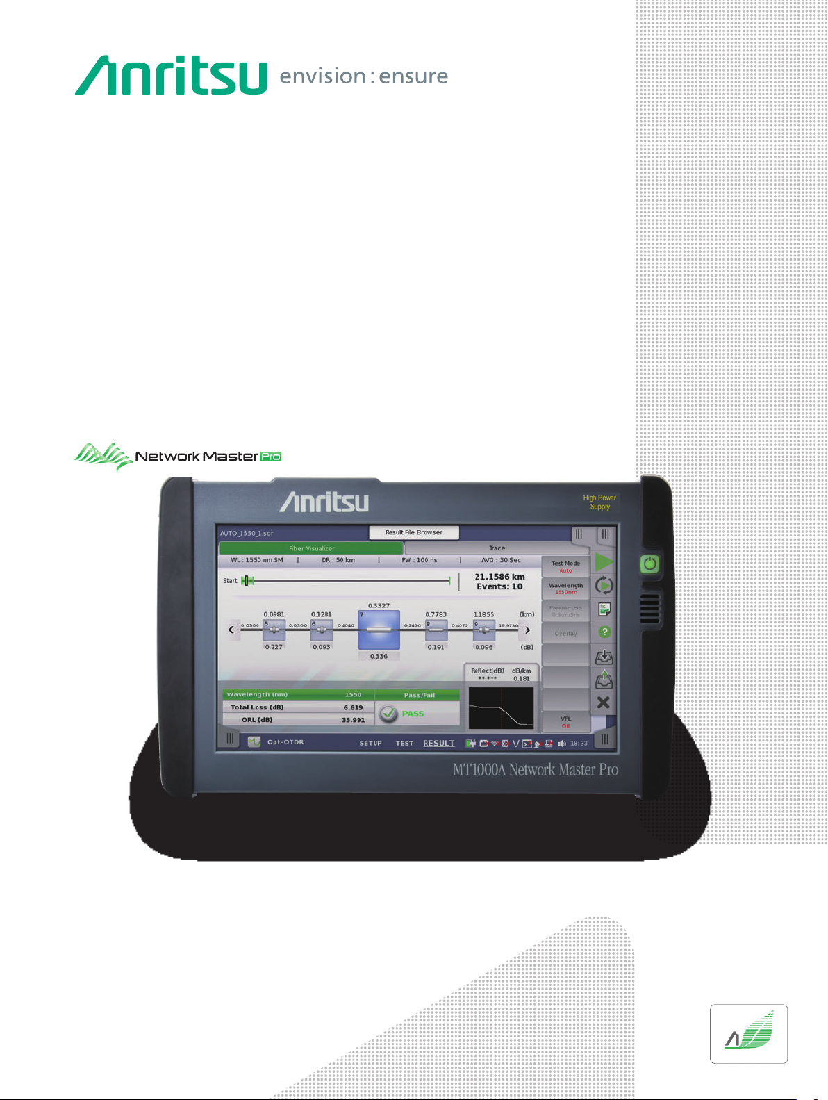
Network Master™ Series
Network Master Pro
MT1000A
OTDR Module
MU100020A 1310/1550 nm SMF
MU100021A 1310/1550 nm SMF, 850/1300 nm MMF
MU100022A 1310/1550/1625 nm SMF
MU100023A 1310/1550 nm SMF, 1650 nm SMF
Product Brochure
Excellent Eco Product
Page 2

Intuitive Fiber Status Monitoring
For Mobile Network I&M
start
2
Network MasterTM Series MT1000A Network Master Pro
MU100020A/21A/22A/23A OTDR Module
MU100020A/21A/22A/23A
Page 3
End
Installing Complex Mobile Networks
The worldwide spread of mobile devices, such as smartphones and tablets using SNS, video streaming, etc., is causing an
explosive increase in data traffic volumes. Mobile network base stations have various configurations; as well as shifting
towards using smaller remote radio head (RRH) installations, optical fiber fault-finding and transport quality tests are
required as the network environment evolves.
Installing the Transport Module MU100010A (10G Multirate)/MU100011A (100G Multirate) and OTDR Module MU100020A/
MU100021A/MU100022A/MU100023A in the Network Master Pro MT1000A supports all-in-one optical-fiber fault finding and
transport quality tests.
Using the MU100020A/MU100021A/MU100022A/MU100023A, scratched or dirty connectors at fiber cable connections can be
detected as fault locations from the excessive optical reflections to support fault finding and troubleshooting of Mobile
optical networks. Additionally, work efficiency is greatly improved using the Fiber Visualizer function supporting Easy-to-Use/
Easy-to-Report testing.
Network Master Pro MT1000A Series Key Applications
All in
One
Easy
All-in-One Optical/Transport Tester
Install OTDR Module and 10G/100G
Multirate Module in one main frame
Easy-to-Use Intuitive GUI Menus
to use
● Compact Lightweight Design for Onsite Testing
● Modular Design for Maximized Investment Efficiency
Mobile Network I&M
Mobile
Backhaul
Fronthaul
Easy
to use
Core and Metro Network Long Range I&M
● Measures Trunk Fibers of 100 km or more and PON Networks with up to 1 × 128 Splitters
● Supports three SM fiber (1310 nm/1550 nm) models (Standard, Enhanced, High-Performance)
● Supporting Construction using Multi-core Fiber Cables
● Supports other Mobile network applications
Mobile Fronthaul and Backhaul Optical Loss and Reflection
Attenuation Measurements
Mobile
・ Supports SM fiber (1310/1550/1625 nm, 1650 nm), MM fiber (850 nm/1300 nm) models
・ All-in-one OTDR, light source, optical power meter, visible light source (option)
・ High-accuracy event detection
・ CPRI/OBSAI measurement with simultaneously installed Multirate Module
MU100010A/MU100011A
Easy-to-Use, Easy-to-Report
・ Graphical summary and Pass/Fail evaluation display using Fiber Visualizer function
・ OTDR simple test mode operation using touch panel
・ One-touch button PDF report output
3
Page 4
Network Master Pro MT1000A, OTDR Module MU100020A/21A/22A/23A
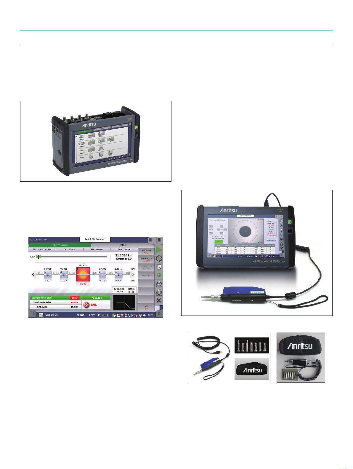
All-in-One
Network I&M is supported by installing the MU100020A/MU100021A/
MU100022A/MU100023A and MU100010A/MU100011A in the MT1000A.
The OTDR Module lineup includes the MU100021A for OTDR
measurements of both SM and MM fibers in high demand by the
Mobile network I&M, plus the MU100020A/MU100022A/MU100023A for
OTDR measurements of SM fiber used by PON networks and long- range
measurements in Core/Metro networks.
With 10G/100G Multirate Module and OTDR Module
Easy-to-Use GUI
The MT1000A GUI design simulates onsite operations to help increase
evaluation efficiency at network installation and to speed-up fault
troubleshooting and isolation. Additionally, the intuitive user interface
operations also help cut training time.
Portable
All test functions required for network verification are built into the
compact MT1000A cabinet for easy, all-in-one onsite support of most
communications standards; the standard soft carry bag accessory is also
ideal for carrying the MT1000A onsite.
Long Battery Life
Since AC power is not commonly available onsite, the MT1000A can run
for up to 6 hours (with OTDR Module) on just one battery charge. And
the optional car 12 Vdc adapter offers in-vehicle charging, helping
facilitate uninterrupted work when moving between sites.
All-in-One Functions Required by Physical Layer I&M Tests
The MU100020A/MU100021A/MU100022A/MU100023A built-in light
source and power meter functions can be used for optical loss tests in
addition to OTDR tests. An optional (Option 002) visible light source
can be installed as well.
Moreover, the presence of scratches and dirt on the fiber end face can
be checked using the Video Inspection Probe (VIP).
Easy-to-Read and Easy-to-Use 9-inch High-Resolution Touch
Screen
The large 9-inch high-resolution, full-color, touch screen is easy to use
and displays easy-to-read measurement results, helping improve onsite
work efficiency.
4
: Separately sold Video Inspection Probe (External G0382A/G0306B)
*
G0382A G0306B
Page 5
Network Master Pro MT1000A, OTDR Module MU100020A/21A/22A/23A
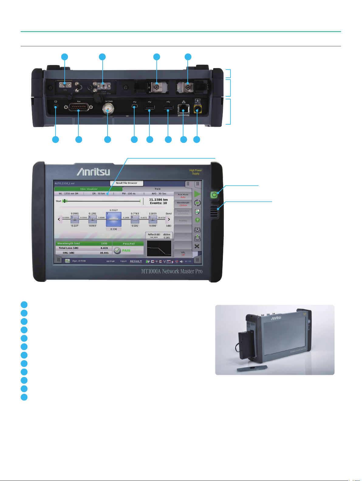
Panel Layout
1 2 3 4
Rear Panel
Module MU100020A/MU100021A/MU100022A/
MU100023A
Main Frame MT1000A
5
1
Visible Light Option
2
Optical Power Meter
3
OTDR Port 1*
4
OTDR Port 2*
5
Audio*
6
AUX (Interface for GPS)*
7
Clock Input*
8
USB Mini-B
9
USB A
10
USB A
11
Ethernet Interface (For Remote Control)
12
DC Input (18 Vdc)
3
6 117 8 9 10 12
1
2
3
3
9-inch High-Resolution Touch Screen
Power Switch
Speaker (Not Used)
Changeable Rechargeable Lithium-Ion Battery Pack
1: MU100021A Multi-mode (850/1300 nm)
*
MU100023A Single-mode (1650 nm)
2: MU100020A/MU100021A/MU100023A Single-mode (1310/1550 nm)
*
MU100022A Single-mode (1310/1550/1625 nm)
3: Not Support for OTDR Module Application
*
5
Page 6
Network Master Pro MT1000A, OTDR Module MU100020A/21A/22A/23A
OTDR Module Applications
Generally, depending on the optical fiber measurement environment, OTDR measurements require multiple settings such as distance range, pulse
width, measurement time, etc., making work difficult for technicians who do not generally use an OTDR. When performing Pass/Fail evaluation of an
optical network for a report, a simple intuitive GUI is key to improving work efficiency.
The MU100020A/MU100021A/MU100022A/MU100023A emphasizes easy-to-understand operability using four application measurement modes:
Standard OTDR Measurement, FTTA Measurement, Construction Mode and OLTS Measurement.
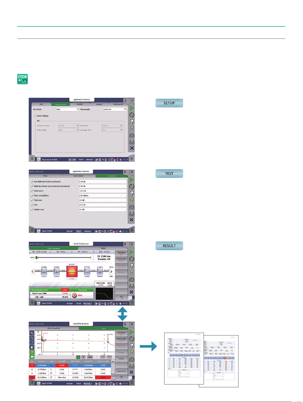
Standard OTDR Measurements
Graphical Display Based on Three-Window Operation: SETUP/TEST/RESULT
This sets the measurement wavelength.
Other conditions, such as distance range, measurement time, etc., are
measured at the Auto setting conditions.
One-Button Screen Switch
This sets the detection conditions for optical fiber connectors and
splices as well as the Pass/Fail evaluation threshold values, and starts
measurement.
This displays the Pass/Fail evaluation results for each event graphically
at the Fiber Visualizer screen.
Additionally, waveform analysis is supported by switching to the Trace
screen.
The measured data are output as a PDF report by an easy one-button
operation.
6
Page 7

Network Master Pro MT1000A, OTDR Module MU100020A/21A/22A/23A
OTDR Module Applications
1: Easy Pass/Fail Evaluation Using Fiber Visualizer
The OTDR measurement results are displayed as a trace showing the
optical fiber length, losses and size of reflections, as well as an easy-toview summary of the analysis results on the Fiber Visualizer screen.
Fiber Visualizer Screen
• Event icons showing characteristics of each connector, splice, and far
end
• Pass/Fail evaluations based on user-settable threshold values
The user can set any threshold value for each event. If the Pass/Fail
evaluation settings prescribed in the engineering manual are set
beforehand, the measured optical fiber loss status can be easily
distinguished visually at the same time as measurement ends.
2: Intuitive Manual Waveform Analysis Using Touch Panel
Operation
Using the Trace screen, it is also possible to perform manual analysis
while moving the cursor on the captured waveform. Since the MT1000A
has a touch panel, the optical fiber length, loss, and reflection
attenuation can be analyzed manually using intuitive direct operations
on the waveform.
3: Supports Long-Distance Optical Fibers and PON Network
Measurements with 1 × 128 Splitters
OTDR measurements of long optical fibers exceeding 100 km as well as
PON networks including many splitters require an OTDR with high
dynamic-range performance.
With its high dynamic range of 46 dB (typical), the MU100020A/
MU100022A is ideal for evaluating Core/Metro/Access optical fiber
networks.
PON Measurement Screen
4: Various Functions and Performance for Precision OTDR
Measurements
0.8-m Event Dead Zone
Events can be detected with a dead zone of just 0.8 m (typical). This is
ideal for measurements in a mixed environment including short optical
fibers, such as patch cords.
0.8 m
Manual Analysis Screen
0.8-m Event Dead Zone
250,001 Sampling Points Max.
Up to 250,001 sampling points are supported, offering a minimum
resolution of 2 cm, and a resolution of 2 m for a distance range of 300 km.
7
Page 8

Network Master Pro MT1000A, OTDR Module MU100020A/21A/22A/23A
OTDR Module Applications
Optical Communications/Connection Check Functions
If an optical data signal is being input to the OTDR from an external
source, the optical fiber connection status will be poor, making it
impossible to perform accurate measurement and analysis. When an
optical data signal is detected at the start of OTDR measurement using
these functions, the optical fiber connection status is evaluated as poor,
a warning is displayed, and measurement is stopped.
Supports OTDR Data Sharing Format
The measured waveform and analysis results data from the Fiber
Visualizer and waveform screens are saved in the same common OTDR
format described in the Telcordia SR-4731 (issue 2) standards. Not only
can saved data be read by these instruments, it can also be read by the
“NETWORKS” Analysis Software running on a PC.
: The PC Analysis Software does not support the Fiber Visualizer function.
*
Macro Bend Detection/Analysis
Macro bends can be detected and analyzed by comparing two waveform
(1310/1550 nm, 1310/1625 nm) measurements using wavelength bend
characteristics, permitting confirmation of bending faults in optical
fibers, which is a difficult evaluation using measurement only one
wavelength.
Multi-waveform Measurement and Display Functions
This is very convenient for comparison with saved waveform data
captured at network commissioning as well as for comparison with
abnormal waveform data, such as that captured at macro bend
measurements.
FTTA Measurements
Comparatively short optical fibers of around several hundred meters in
length are usually installed at the Mobile fronthaul FTTA. In this type of
measurement environment, measurements made by different operators
under different conditions commonly have inconsistency problems at
later data processing.
At FTTA measurement, the optical fiber installation measurement
conditions are fixed previously, so measurements are always made
under the same conditions.
Like the OTDR measurement function, each measurement result can be
analyzed at the Trace and Fiber Visualizer screens.
OLTS Measurements
At measurement of the optical fiber, the first basic measurement is loss
measurement using a light source and power meter. With a built-in
light source and power meter as standard, the MU100020A/
MU100021A/MU100022A/MU100023A can be used as an optical loss
test set (OLTS).
In addition, measurement results can be managed at the Loss Table for
Pass/Fail evaluation of individual data based on set threshold values.
OLTS Measurement Loss Table
Const-
ruction
Construction Mode
The “Construction mode” simplifies installation work and is especially
useful when pulling multi-core fiber cables. Work mistakes are
eliminated by automated operation using pre-settings, such as project
data (number of fibers, file names, etc.) and measurement conditions, to
facilitate efficient measurement of multi-core fiber cables.
8
Construction Mode
FTTA Measurements
Page 9

Network Master Pro MT1000A, OTDR Module MU100020A/21A/22A/23A
Other Shared Functions
Optical Connector End Face Inspection
This function is for analyzing the presence and state of scratches and
dirt on the fiber end face, which are one factor causing degraded
optical communications quality. Additionally, connecting a dirty or
scratched optical fiber directly to an OTDR can prevent Pass/Fail
evaluation of a previously normal fiber.
The MT1000A has a built-in VIP utility menu for analyzing the end face
of optical connectors. When the external optical fiberscope (G0382A
USB Autofocus type, G0306B USB Standard type: sold separately) is
connected, scratches and dirt on the optical connector end face can be
confirmed visually. Pass/Fail evaluation of the end-face status is
performed according to the IEC61300-3-35 standard.
Optical Fiber End Face Inspection Screen
PDF Report Output
OTDR/FTTA measurement results can be output as a PDF report.
In addition to the summary display, the Fiber Visualizer event icons,
event table, and a waveform display can also be output. This is useful
for easy confirmation of the Pass/Fail evaluation status.
In addition, files obtained by VIP measurement can also be read as well,
creating a single convenient report.
Simultaneous Visible Light Option/Optical Power Meter
Measurements
The visible light option (Option 002) can be used jointly with each of
the Standard OTDR, FTTA, Construction and OLTS applications, making
it possible to visually confirm breaks in the optical fiber. Furthermore,
the Standard OTDR, FTTA and Construction applications can also be
used jointly with an optical power meter, increasing work efficiency
when measuring multi optical fibers.
OTDR Operation with Optical Power Meter
Value of Offering Automatic Measurement Solutions
Simplifies multiple testing work, shortens on-site test time, and
eliminates human operation errors. Supports simultaneous multiple
tests. Download free editing software (MX100003A) to create scenarios
without need for programing skills.
PDF Report
Automation Test Select
SEEK (Scenario Edit Environment Kit)
MX100003A
9
Page 10

Network Master Pro MT1000A, OTDR Module MU100020A/21A/22A/23A
Other Shared Functions
Remotely Controlled Network Installation, Start-up, and Maintenance
The MT1000A has a useful remote function for network installation, start-up and maintenance. Connecting the office and job site via LAN allows
engineers in the office to see screens at the on-site instrument while making settings and measurements, and troubleshooting. This provides an
efficient link between engineers and on-site measurements to help cut network installation and maintenance costs.
LAN
Operation Center
Technician
Easy Connections Anywhere Using SORA (Site Over Remote Access)*
Using the MX109020A Site Over Remote Access (SORA hereafter) software measuring instruments can be remotely controlled easily anywhere.
The SORA cloud-based service allows office users to log-in to an Internet webpage to control the measuring instrument from the office via a smartphone.
Log-in to server
via web browser
Office
intranet
Internet
Easy control of measuring
instrument via server log-in
Smartphone
network
3G/LTE WLAN
Login
Login screen
This service can be used in countries and regions where the MT1000A WLAN/Bluetooth option has been approved. For details, contact Anritsu.
*
To connect using SORA, you must purchase an option license for the main unit as well as a subscription license.
*
Refer to the MX109020A leaflet and product introduction for more details. You must agree to the service contract before purchasing SORA.
Refer to the service contract at the following URL: https://www.anritsu.com/en-AU/test-measurement/support/downloads/manuals/dwl20059.
Remote control screen
10
Page 11

Network Master Pro MT1000A, OTDR Module MU100020A/21A/22A/23A Specifications
MT1000A + MU100020A/MU100021A/MU100022A/MU100023A
Display 9-inch active TFT display (800 × 480 pixels) and touch screen
Supported Languages User selectable (English, Japanese, Simplified Chinese, Russian, French, Spanish, Finnish, Korean, German)
USB Data Interface MT1000A operates as host: USB 2.0 type A (2 ports), MT1000A operates as device: USB 2.0 type Mini-B (1 port)
Ethernet Interface Ethernet 10M/100M/1000M, Connector: RJ45
WLAN Interface* IEEE 802.11 b/g/n
Bluetooth Interface* Bluetooth 2.1 +EDR
Audio Interface For connection of head set, Connector: 3.5-mm diameter jack
AUX Connector For connection of optional G0325A GPS receiver
Built-in Loudspeaker Monitors speech of voice channel, Output level: user-controlled from user Interface
Ext. Clock Input
Dimensions and Mass
Mains Adapter
Battery
Environmental Conditions
EMC 2014/30/EU, EN61326-1, EN61000-3-2
CE
: Available for certified countries and regions including USA, Canada, Japan and EU countries. Please visit the Anritsu web site for updated information.
*
The Bluetooth
LVD 2014/35/EU, EN61010-1
RoHS 2011/65/EU, EN50581
®
wordmark and logos are owned by the Bluetooth SIG, Inc. and any use of such marks by Anritsu is under license.
For connection of external clock signals:
SETS (E1: 2.048 Mbps), BITS (DS1: 1.544 Mbps) or 2.048 MHz TTL signal in accordance with ITU-T G.703, 10 MHz, Connector: BNC
MU100020A/MU100021A/MU100022A/MU100023A: 257.6 (W) × 163 (H) × 25 (D) mm (without rear panel), ≤0.8 kg
with MT1000A: 257.6 (W) × 163 (H) × 84.3 (D) mm, 2.7 kg including battery (G0310A)
with MT1000A/MU100010A: 257.6 (W) × 163 (H) × 102.2 (D) mm, 3.5 kg including battery (G0310A)
Input: 100 V(ac) to 240 V(ac), 50 Hz/60 Hz
Output: 18 V(dc), 3.62 A (max.)
Power Consumption: ≤65 W
With MT1000A-006
Input: 100 V(ac) to 240 V(ac), 50 Hz/60 Hz
Output: 18 V(dc), 6.6 A (max.)
Power Consumption: ≤120 W
10.8 V rechargeable and replaceable intelligent Li-ion battery
Operating time: 6.0 h (with MU100020A/MU100021A/MU100022A/MU100023A), Telcordia GR-196-CORE Issue2, September 2010, 25°C
Operating Temperature: 0° to +50°C, ≤85%RH (non-condensing) (with MU100020A/MU100021A/MU100022A/MU100023A)
Charging Temperature: 0° to +50°C, ≤85%RH (non-condensing)
Storage Temperature: –30° to +60°C, ≤90%RH (non-condensing)
(without battery or AC adapter, with MU100020A/MU100021A/MU100022A/MU100023A)
–20° to +50°C, ≤90%RH (non-condensing)
(with battery and AC adapter, with MU100020A/MU100021A/MU100022A/MU100023A)
MU100020A/MU100021A/MU100022A/MU100023A OTDR Module Common Specifications
IOR Setting 1.300000 to 1.700000 (0.000001 steps)
Units km, m, kft, ft, mi
Sampling Points Up to 250,001
Sampling Resolution 0.02, 0.05, 0.1, 0.2, 0.5, 1, 2, 5, 10, 20, 40 m
Loss measurement accuracy
(linearity)
Reflectance Accuracy Single mode: ±2 dB, Multimode: ±4 dB
Distance Accuracy ±1 m ±3 × measurement distance × 10
Distance Range
(IOR = 1.50000)
Realtime Sweep Time ≤0.2 sec. (Test Mode: Manual, Distance Range: 50 km, Resolution: Coarse)
Testing Modes
Fiber Event Analysis
OTDR Trace Format Telcordia universal. SOR, issue 2 (SR-4731)
Other Functions
±0.05 dB/dB or ±0.1 dB (whichever is greater)
-5
± marker resolution (excluding IOR uncertainty)
Single mode: 0.5, 1, 2.5, 5, 10, 25, 50, 100, 200, 300 km
Multimode: 0.5, 1, 2.5, 5, 10, 25, 50, 100 km
Standard OTDR application: Selectable automatic or manual set-up, Fiber Visualizer, Trace analysis, Light source, Power meter,
FTTA application: Automatic set-up, Fiber Visualizer, Trace analysis, Light source, Power meter, Visual fault locator (Optional)
Construction application: OTDR Measurement, Auto Save, Multi-core fiber measurements, Power meter,
OLTS application: Power meter and Light source, Loss Table, Visual fault locator (Optional)
Fiber condition setup: Patch-cord setup (Launch/Receive), Splitter Setup (Up to 128 branch)
User defined Auto detect threshold:
Event loss (Reflective and non-reflective), Reflectance, Fiber end, Macro bend detect ON/OFF, Splitter detect: Up to 128 branch
User defined PASS/FAIL thresholds:
Non-reflective event loss (fusion), Reflective event loss (connector, mechanical), Reflectance, Fiber loss (dB/km),
Total loss, ORL, Splitter loss (Up to 128 branch)
Loss modes: Splice loss, 2-pt loss, 2-pt LSA, dB/km loss, dB/km LSA, ORL
Averaging modes: Timed (5, 10, 15, 30 sec, 1, 2, 3, 5, 10 min.)
Live Fiber detect : Verifies presence of communication light in optical fiber
Connection check: Automatic check of OTDR to FUT connection quality
Visual fault locator (Optional)
Visual fault locator (Optional)
Remote Operation, Both-End Measurement
11
Page 12

Network Master Pro MT1000A, OTDR Module MU100020A/21A/22A/23A Specifications
MU100020A OTDR Module
Options Wavelength*
MU100020A-020
MU100020A-021 42 dB/41 dB*
1310 nm/1550 nm ±25 nm
MU100020A-022
1
Fiber Type Pulse Width
Dynamic Range
39 dB/37.5 dB*
Single Mode Fiber
(SMF) 10 μm/125 μm
ITU-T G.652
3, 10, 20, 50, 100, 200, 500, 1000,
2000, 4000, 10000, 20000 ns
46 dB/46 dB*
25 dB/25 dB*6
(Pulse width: 100 ns)
MU100021A OTDR Module
Options Wavelength*
MU100021A-021
1310 nm/1550 nm ±25 nm
850 nm/1300 nm ±30 nm
1
Fiber Type Pulse Width
Single Mode Fiber
(SMF) 10 μm/125 μm
ITU-T G.652
SMF: Same as MU100020A
1300 nm (MMF):
3, 10, 20, 50, 100, 200, 500,
1000, 2000, 4000 ns
GI Fiber
62.5 μm/125 μm*
7
850 nm (MMF):
3, 10, 20, 50, 100, 200, 500 ns
Dynamic Range
42 dB/41 dB*
29 dB/28 dB*
MU100022A OTDR Module
Options Wavelength*
MU100022A-022 1310/1550/1625 nm ±25 nm
1
Fiber Type Pulse Width
Single Mode Fiber
(SMF) 10 μm/125 μm
ITU-T G.652
3, 10, 20, 50, 100, 200, 500, 1000,
2000, 4000, 10000, 20000 ns
Dynamic Range
46/46/44 dB*
25/25/23 dB*
(Pulse width: 100 ns)
Deadzone
3
*2,
*
(Fresnel)*
(IOR = 1.500000)
6
6
6
≤80 cm (typ.) ≤3.8 m/4.3 m
Deadzone
3
*2,
*
(Fresnel)*
(IOR = 1.500000)
6
≤80 cm (typ.)
6
Deadzone
3
*2,
*
(Fresnel)*
(IOR = 1.500000)
6
≤80 cm (typ.) ≤3.8/4.3/4.8 m
6
4
(Backscatter)*
(IOR = 1.500000)
4
(Backscatter)*
(IOR = 1.500000)
≤3.8 m/4.3 m
≤4.0 m/5.0 m
4
(Backscatter)*
(IOR = 1.500000)
Deadzone
Deadzone
Deadzone
5
5
5
MU100023A OTDR Module
Distance
1
Fiber Type Pulse Width
Single Mode Fiber
(SMF) 10 μm/125 μm
ITU-T G.652
3, 10, 20, 50, 100, 200, 500, 1000,
2000, 4000, 10000, 20000 ns
SNR = 1
Options Wavelength*
MU100023A-021
Laser Safety*
1: 25°C, Pulse width: 1 μs (1310/1550/1625/1650 nm), 100 ns (850 nm/1300 nm),
*
Except for when charging the battery.
2: Pulse widths: 20 μs (1310/1550/1625/1650 nm), 500 ns/4 μs (850 nm/1300 nm)
*
Distance range: 100 km (1310/1550/1625/1650 nm), 25 km (850 nm/1300 nm)
1310/1550 nm ± 25 nm
1645 nm to 1655 nm
IEC 60825-1: 2007 CLASS 1M:
9
21 CFR1040.10 Excludes deviations caused by conformance to Laser Notice No. 50 dated June 24, 2007
Averaging: 180 sec., SNR = 1, 25°C
Except for when charging the battery.
3: Dynamic range (one-way back-scattered light), SNR = 1: The level difference
*
between the RMS noise level and the level where near end back-scattering
occurs.
Level
Deadzone
Dynamic Range
8
*2,
*3,
*
(Fresnel)*
(IOR = 1.500000)
6
42/41/35 dB*
4: Pulse width: 3 ns, Return loss: 40 dB, 25°C (Refer to the figure below)
*
Except for when charging the battery.
1.5 dB
0.5 dB
5: Pulse width 10 ns, return loss 55 dB, Deviation ±0.5 dB, 25 ±5°C
*
6: Typical. Subtract 1 dB for guarantee
*
7: At measurement of 50 μm/125 μm MM Fiber, the dynamic range drops by
*
about 3.0 dB
8: At 1650 nm: With background light, 1310/1550 nm, –19 dBm CW light
*
9: Safety measures for laser products
*
This product complies with optical safety standards in IEC 60825-1,
≤80 cm (typ.) ≤5.0/5.5/6.5 m
Fresnel reflection
Back-scattered light
4
(Backscatter)*
(IOR = 1.500000)
Deadzone
21CFR1040.10 and 1040.11; the following descriptive labels are affixed to the
product.
5
12
Page 13

Network Master Pro MT1000A, OTDR Module MU100020A/21A/22A/23A Specifications
Light Source Specifications
Standard on all models
Stabilized Light Source (through OTDR port)
Options MU100020A MU100021A MU100022A MU100023A
Wavelength*
Spectral Width*
Fiber Type
Optical Connector Same as OTDR
Output Power*
Output Stability*
Modes of Operation CW, 270 Hz, 1 kHz, 2 kHz
Warm up time 10 min.
Laser Safety Same as OTDR
1
1
1
2
1310 nm/1550 nm ±30 nm
≤5 nm (1310 nm)
≤10 nm (850/1300/1550/1625 nm)
≤3 nm (1650 nm)
Single Mode Fiber (SMF)
10 μm/125 μm ITU-T G.652
–5 ±1.5 dBm
≤0.1 dB (1310/1550/1625/1650 nm)
1310 nm/1550 nm ±30 nm
850 nm/1300 nm ±30 nm
Single Mode Fiber (SMF)
10 μm/125 μm ITU-T G.652
GI Fiber 62.5 μm/125 μm
Power Meter Specifications
Standard on all models
Standard Power Meter (Dedicated port)
Fiber Type Single Mode (SMF) 10 μm/125 μm ITU-T G.652, GI Fiber 62.5 μm/125 μm
Wavelength Range 800 nm to 1700 nm
Setting Wavelengths 1310, 1490, 1550, 1625, 1650, 850, 1300 nm
Measurement Range
Optical Connector 2.5 mm/1.25 mm Universal
Accuracy*
Modes of Operation CW, 270 Hz, 1 kHz, 2 kHz
3
–67 to +6 dBm (CW, 1550 nm, –60 to +3 dBm @850 nm)
–70 to +3 dBm (Modulation, 1550 nm, –63 to 0 dBm @850 nm)
±5% (–10 dBm, 1310 nm/1550 nm, CW, 25°C, Using Master FC fiber and 2.5 mm universal connector)
±10% (–10 dBm, 850 nm, CW, 25°C, Using Master FC fiber and 2.5 mm universal connector)
1310/1550/1625 nm ±30 nm
Single Mode Fiber (SMF)
10 μm/125 μm ITU-T G.652
1310/1550 nm ±30 nm
1650 nm ±5 nm
Single Mode Fiber (SMF)
10 μm/125 μm ITU-T G.652
Visible Light Source (Option 002)
Central Wavelength 650 nm ±15 nm (at 25°C)
Optical Output 0 ±3 dBm (CW, 25°C)
Output Optical Fiber 10 μm/125 μm, SMF (ITU-T G.652)
Optical Connector 2.5 mm universal
Output Function OFF, CW, Blink
Laser Safety*
1: CW, 25°C
*
2: CW, –10° to +50°C (±1°C) difference between max/min. values over 1 minute, SM fiber 2 m, when an optical power meter with 40 dB or greater return loss is used
*
(SM),after warming up.
3: After zero offset
*
4: Safety measures for laser products
*
This option complies with optical safety standards in IEC 60825-1, 21CFR1040.10 and 1040.11; the following descriptive labels are affixed to the product
4
IEC 60825-1: 2007 CLASS 3R 21CFR1040.10 and 1040.11 Excludes deviations caused by conformance to Laser Notice No. 50 dated June
24, 2007
13
Page 14

Ordering Information
Network Master Pro MT1000A, OTDR Module MU100020A/21A/22A/23A
Please specify the model/order number, name and quantity when ordering.
The names listed in the chart below are Order Names. The actual name of the item may dier from the Order Name.
1) Mainframe
Model/Order No. Name
MT1000A Network Master Pro
Standard Accessories
MT1000A-006*
B0745A
B0728A*
G0385A*
G0310A
Z1746A
Z1747A*
Z1748A*
Z1817A*
MT1000A-003*
MT1000A-005*
1: The presence of the MT1000A-006 option can be recognized at the top right
*
of the front panel. To retrofit to the already shipped item, please contact us.
Without MT1000A-006 With in MT1000A-006
2: One line cord is attached to the area to shipment.
*
3: Set of B0720A (Rear Cover) and B0732A (Screw Kit).
*
Please refer to next page "Module Configuration" for details.
4: The MT1000A with MT1000A-006 can be used. Use the AC adapter when
*
using the MT1000A without MT1000A-006 installed.
5: Shoulder strap for MT1000A.
*
6: Hand strap for MT1000A.
*
7: This DVD includes PDF files and formatting tools of each product's instruction
*
manual (such as W3933AE, W3810AE, W3736AE, W3946AE).
8: Available for certified countries and regions including USA, Canada, Japan and
*
EU countries. Please visit the Anritsu web site for updated information.
9: MT1000A-005 is required for MU100090A. To retrofit to the already shipped
*
item, please contact us.
1
High Power Supply: Installed
Line Cord*
3
4
5
6
7
Softcase: 1 pc
Rear Panel kit: 1 pc
High Power AC Adaptor: 1 pc
Li-ion Battery: 1 pc
Stylus: 1 pc
Carrying Strap: 1 pc
Handle: 1 pc
Utilities ROM: 1 pc
Main Frame Option
8
Connectivity for WLAN/Bluetooth
9
AUX I/O
2
: 1 pc
2) Select OTDR Module
Select the OTDR module configuration according to the procedures in
items 2-1) and 2-2) below.
2-1) Select Base Module
Select one of the following models.
Model/Order No.*
MU100020A
MU100021A
MU100022A
MU100023A
J1693A
J1694A
W3811AE
10: Factory installed option only and cannot be retrofitted.
*
10
OTDR Module (1310/1550 nm SMF)
OTDR Module (1310/1550/850/1300 nm SMF/MMF)
OTDR Module (1310/1550/1625 nm SMF)
OTDR Module (1310/1550/1650 nm SMF)
Standard Accessories
Universal Connector 2.5 mm for OPM: 1 pc
Universal Connector 1.25 mm for OPM: 1 pc
Quick Reference Guide: 1 pc
Name
2-2) Select Dynamic Range Type
Select one of the following models.
Model/Order No.*
MU100020A-020
MU100020A-021
MU100020A-022
MU100021A-021
MU100022A-022
MU100023A-021
11: Factory installed option only and cannot be retrofitted.
*
11
Standard Dynamic Range (1310/1550 nm: 39/37.5 dB)
Enhanced Dynamic Range (1310/1550 nm: 42/41 dB)
High-Performance Dynamic Range
(1310/1550 nm: 46/46 dB)
Enhanced Dynamic Range
(1310/1550/850/1300 nm: 42/41/29/28 dB)
High-Performance Dynamic Range
(1310/1550/1625 nm: 46/46/44 dB)
Enhanced Dynamic Range
(1310/1550 nm: 42/41 dB, 1650 nm: 35 dB)
Name
3) Select Connector Types
14
Page 15

Ordering Information
Network Master Pro MT1000A, OTDR Module MU100020A/21A/22A/23A
Select a module polish type and connector adapter according to the
procedures in items 3-1) and 3-2).
3-1) Polish Types
Specify one connector polish type.
Model/Order No.*
MU100020A-010
MU100020A-011*
MU100021A-010
MU100021A-011*
MU100022A-010
MU100022A-011*
MU100023A-010
MU100023A-011*
12: Factory installed option only and cannot be retrofitted.
*
13: Used by SM port. An APC connector cannot be specified for the MM port,
*
which uses a UPC connector.
12
13
13
13
13
Name
UPC Polish
APC Polish
UPC Polish
APC Polish
UPC Polish
APC Polish
UPC Polish
APC Polish
3-2) Select Connector Adapter type
Specify one type of connector adapter.
Model/Order No. Name
For UPC Polish with Option 010
MU100020A-037*
MU100020A-039*
MU100020A-040*
MU100021A-037*
MU100021A-039*
MU100021A-040*
MU100022A-037*
MU100022A-039*
MU100022A-040*
MU100023A-037*
MU100023A-039*
MU100023A-040*
MU100020A-025*
MU100020A-026*
MU100021A-025*
MU100021A-026*
MU100022A-025*
MU100022A-026*
MU100023A-025*
MU100023A-026*
14: One specified connector adapter supplied free of charge.
*
15:
One each of same connector adapter for SM port and MM port supplied free of
*
charge. Cannot specify different connector adapters for each port.
16: One connector adapter for SM port supplied free of charge.
*
One connector adapter equivalent to Option 37 (FC/UPC) for MM port
supplied free of charge.
17: One specified connector adapter for SM port supplied free of charge.
*
One connector adapter equivalent to Option 40 (SC/UPC) for MM port
supplied free of charge.
18: One each of same connector adapter for SM port (1310/1550 nm) and SM
*
port (1650 nm) port supplied free of charge.
Cannot specify different connector adapters for each port.
14
FC Connector
14
DIN 47256 Connector
14
SC Connector
15
FC Connector
15
DIN 47256 Connector
15
SC Connector
14
FC Connector
14
DIN 47256 Connector
14
SC Connector
18
FC Connector
18
DIN 47256 Connector
18
SC Connector
For APC Polish with Option 011
14
FC Connector key width 2.0 mm
14
SC Connector
16
FC Connector key width 2.0 mm
17
SC Connector
14
FC Connector key width 2.0 mm
14
SC Connector
18
FC Connector key width 2.0 mm
18
SC Connector
4) VFL
Model/Order No.*
MU100020A-002*
MU100021A-002*
MU100022A-002*
MU100023A-002*
19: Factory installed option only and cannot be retrofitted.
*
20: Installs dedicated port for visible light source; 2.5 mm universal light receiver
*
type (connector adapter not required). J1335A required to connect 1.25 mm
fiber.
19
20
Visual Fault Locator
20
Visual Fault Locator
20
Visual Fault Locator
20
Visual Fault Locator
Name
5) Replacement Adapters
MU100020A
Model/Order No.
J0617B (FC/UPC)
J0618E (DIN/UPC)
J0619B (SC/UPC)
J0739A (FC/APC)
J1697A (SC/APC)
21: There are two SM ports — one for 1310/1550 nm, and another for 1650 nm.
*
MU100022A
MU100023A*
21
MU100021A
For UPC Polish
SM port SM port MM port
For APC Polish
SM port SM port MM port
N/A
N/A
15
Page 16

Ordering Information
Network Master Pro MT1000A, OTDR Module MU100020A/21A/22A/23A
6) Select Accessories & Replacement Items
Model/Order No. Name Description
For MT1000A Mainframe
B0691B
G0324A
J1569B
G0382A
G0306B
G0309A
B0720A
B0728A
B0729A
B0730A
B0731A
B0732A
W3810AE
J1335A
J1530A
J1531A
J1532A
J1533A
J1534A
J1535A
NETWORKS
J1579A
J1581A
J1575A
J1571A
Hard Case
Battery Charger
Car 12 Vdc Adapter
Autofocus Video Inspection Probe
Video Inspection Probe (X400)
AC Adapter
Rear Cover
Rear Panel Kit
Screw 1U
Screw 2U
Screw 3U
Screw Kit
For MU100020A/MU100021A/MU100022A/MU100023A OTDR Modules
MT1000A MU100020A Network Master Pro
Operation Manual
MU/LC Connector Adapter
SC Plug-in Converter (UPC(P)-APC(J))
SC Plug-in Converter (APC(P)-UPC(J))
FC Plug-in Converter (UPC(P)-APC(J))
FC Plug-in Converter (APC(P)-UPC(J))
LC-SC Plug-in Converter (for SM, SC(P)-LC(J))
LC-SC Plug-in Converter (for MM, SC(P)-LC(J))
PC Emulation Software for Data Analysis and Reporting
Optical cable SM LC/PC to LC/PC 3 m
Optical cable MM LC/PC to LC/PC 3 meter
Optical cable SM LC/PC to FC/PC 3 m
Optical cable SM LC/PC to SC/PC 3 m
Up to two installed modules
Fixed x400 magnification (USB Autofocus type).
For visually verifying fiber end-face condition using MT1000A Utility application
Fixed x400 magnification (USB Standard type).
For visually verifying fiber end-face condition using MT1000A Utility application
Use the AC Adapter when using the MT1000A without MT1000A-006 installed
MT1000A Rear Cover
Rear Panel and Screw kit (Same as Standard accessory)
1 unit screw set (Total 4 pcs)
2 units screw set (Total 4 pcs)
3 units screw set (Total 4 pcs)
1U, 2U, 3U screw set (Total 12 pcs)
Printed Matter
Converts ferrule connector diameter from 2.5 mm → 1.25 mm for visible light source
(Option 002)
SC/UPC → SC/APC Adapter
SC/APC → SC/UPC Adapter
FC/UPC → FC/APC Adapter
FC/APC → FC/UPC Adapter
SC/UPC → LC/UPC Adapter for SM fiber
SC/UPC → LC/UPC Adapter for MM fiber
7) Maintenance Service
Model/Order No. Description
MT1000A-ES210
MT1000A-ES310
MT1000A-ES510
MU100020A-ES210
MU100020A-ES310
MU100020A-ES510
MU100021A-ES210
MU100021A-ES310
MU100021A-ES510
MU100022A-ES210
MU100022A-ES310
MU100022A-ES510
MU100023A-ES210
MU100023A-ES310
MU100023A-ES510
2 Years Extended Warranty Service
3 Years Extended Warranty Service
5 Years Extended Warranty Service
2 Years Extended Warranty Service
3 Years Extended Warranty Service
5 Years Extended Warranty Service
2 Years Extended Warranty Service
3 Years Extended Warranty Service
5 Years Extended Warranty Service
2 Years Extended Warranty Service
3 Years Extended Warranty Service
5 Years Extended Warranty Service
2 Years Extended Warranty Service
3 Years Extended Warranty Service
5 Years Extended Warranty Service
Example of Ordering Configuration
1) MT1000A Network Master Pro
2-1) MU100020A OTDR Module (1310/1550 nm SMF)
2-2) MU100020A-020 Standard Dynamic Range
3-1) MU100020A-010 UPC Connector
3-2) MU100020A-037 FC Connector
1) MT1000A Network Master Pro
2-1) MU100021A
2-2) MU100021A-021 Enhanced Dynamic Range
3-1) MU100021A-011 APC Connector
3-2) MU100021A-025 FC Connector key width 2.0 mm
4) MU100021A-002 Visual Fault Locator Option
5) J0619B Replaceable Optical Connector (SC)
• One must be specified from items 1), 2-1), 2-2), 3-1), and 3-2), but specification
from 1) is not required if the MT1000A main frame is not required.
• When the MU100020A is specified in item 2-1), select from the MU100020A
options for models for item 2-2) and later.
OTDR Module (1310/1550/850/1300 nm SMF/MMF)
16
Page 17

Ordering Information
Network Master Pro MT1000A, OTDR Module MU100020A/21A/22A/23A
8) Remote Software Service
The following licenses must be purchased to use the MX109020A Site Over Remote Access.
Mainframe Option License
Model/Order No. Name
MT1000A-003*
MT1000A-011*
22: Available for certified countries and regions including USA, Canada, Japan and EU countries. Please visit the Anritsu web site for updated information.
*
The Bluetooth
23: Validity period is unlimited. An open TCP port may be required to allow the MT1000A to be connected from an in-company LAN to MX109020A, depending on the
*
LAN security policy.
22
23
Subscription Option License
Model/Order No. Name
MX109020A*
MX109020A-TL001*
MX109020A-001*
MX109020A-002*
24: We recommend purchasing a 1-year license in addition to the basic license.
*
25: When extending the usage period, we recommend purchasing in 1-year license periods
*
26: Up to two measuring instruments can be remotely controlled simultaneously with the basic license.
*
27: You must agree to the service terms before purchasing SORA.
*
28: This product cannot be used in some regions and countries; please read the service terms for more details.
*
24, *26, *27, *28
26
26
This number can be increased to up to 8 units by purchasing the MX109020A-001 option, and up to 100 units by purchasing the MX109020A-002 option.
Refer to the service terms at the following URL: https://www.anritsu.com/en-AU/test-measurement/support/downloads/manuals/dwl20059
WLAN/Bluetooth Connect
Site Over Remote Access Connect
®
mark and logos are registered trademarks of Bluetooth SIG, Inc.
Site Over Remote Access Basic License
24, *25
Site Over Remote Access 1 Year License
Site Over Remote Access 8 Units
Site Over Remote Access Unlimited Units
17
Page 18

Ordering Information
Network Master Pro MT1000A, OTDR Module MU100020A/21A/22A/23A
Module Configuration*
1 Module
29
*
30
*
*
2 Modules
3 Modules
29: Any modular combination as shown in a figure.
*
30: Required if the transport modules is not used rear cover (B0720A).
*
30
MT1000A
10G Multirate MU100010A
30
100G Multirate MU100011A
1310/1550 nm SMF MU100020A
1310/1550/850/1300 nm SMF/MMF MU100021A
1310/1550/1625 nm SMF MU100022A
1310/1550 nm, 1650 nm SMF MU100023A
MU100040B
MU100090A
Network Master Pro
Transport Module
OTDR Module
CPRI RF Module
High Performance GPS Disciplined Oscillator
18
Page 19

Network Master Pro MT1000A, OTDR Module MU100020A/21A/22A/23A
Related Products
Network Master Pro MT1000A
10G Multirate Module MU100010A
100G Multirate Module MU100011A
Installing the MU100010A or MU100011A in the MT1000A supports commissioning and
maintenance tests of communications networks operating at speeds from 1.5 Mbps to 100 Gbps.
In addition to Ethernet, OTN, eCPRI/RoE/CPRI/OBSAI, Fibre Channel and SyncE protocols used by
mobile-network base stations are supported too.
CPRI RF Module MU100040B
Installing the CPRI RF Module MU100040B in the MT1000A supports analysis of IQ signal
frequency characteristics included in CPRI signals between the LTE base station RRH and BBU. This
can be used to check operation of the RRH after installation.
MU100040B supported BBU emulation for RRH.
Network Master Flex MT1100A
All-in-one, up to 4-port transport tester supporting from 1.5 Mbps to 100 Gbps including OTN,
Ethernet, eCPRI/RoE/CPRI/OBSAI, Fibre Channel, SDH/SONET and PDH/DSn.
MT9090A Series
µOTDR Module MU909014/15
Compact OTDR for full automatic verification of optical networks, FTTH-PON, Metro and Core.
Gigabit Ethernet Module MU909060A
Dedicated field test solution for installation and troubleshooting Ethernet links in access networks.
Light Source/Optical Power Meter CMA5 Series
For optical fiber installation and maintenance.
ACCESS Master MT9085 Series
For WAN/MFH/DCI/FTTH Optical Fiber I&M
• Improved operability with powerful synergy of 8-inch touchscreen
and hardware keys
• At-a-glance Pass/Fail evaluation using Fiber Visualizer
• All OTDR, OLTS, and Visible Light Source operations on one screen
• Short event dead zone of ≤0.8 m and high dynamic range of
46 dB max.
• Power meter option for measuring optical power up to +30 dBm
MU909014/15
MU909060A
19
Page 20

•
United States
Anritsu Americas Sales Company
450 Century Parkway, Suite 190, Allen, TX 75013 U.S.A.
Phone: +1-800-Anritsu (1-800-267-4878)
•
Canada
Anritsu Electronics Ltd.
700 Silver Seven Road, Suite 120, Kanata,
Ontario K2V 1C3, Canada
Phone: +1-613-591-2003
Fax: +1-613-591-1006
•
Brazil
Anritsu Eletronica Ltda.
Praça Amadeu Amaral, 27 - 1 Andar
01327-010 - Bela Vista - Sao Paulo - SP, Brazil
Phone: +55-11-3283-2511
Fax: +55-11-3288-6940
•
Mexico
Anritsu Company, S.A. de C.V.
Blvd Miguel de Cervantes Saavedra #169 Piso 1, Col. Granada
Mexico, Ciudad de Mexico, 11520, MEXICO
Phone: +52-55-4169-7104
•
United Kingdom
Anritsu EMEA Ltd.
200 Capability Green, Luton, Bedfordshire, LU1 3LU, U.K.
Phone: +44-1582-433200
Fax: +44-1582-731303
•
France
Anritsu S.A.
12 avenue du Québec, Bâtiment Iris 1- Silic 612,
91140 VILLEBON SUR YVETTE, France
Phone: +33-1-60-92-15-50
Fax: +33-1-64-46-10-65
•
Germany
Anritsu GmbH
Nemetschek Haus, Konrad-Zuse-Platz 1,
81829 München, Germany
Phone: +49-89-442308-0
Fax: +49-89-442308-55
•
Italy
Anritsu S.r.l.
Via Elio Vittorini 129, 00144 Roma, Italy
Phone: +39-6-509-9711
Fax: +39-6-502-2425
•
Sweden
Anritsu AB
Isafjordsgatan 32C, 164 40 KISTA, Sweden
Phone: +46-8-534-707-00
•
Finland
Anritsu AB
Teknobulevardi 3-5, FI-01530 VANTAA, Finland
Phone: +358-20-741-8100
Fax: +358-20-741-8111
•
Denmark
Anritsu A/S
c/o Regus Winghouse, Ørestads Boulevard 73, 4th floor,
2300 Copenhagen S, Denmark
Phone: +45-7211-2200
•
Russia
Anritsu EMEA Ltd.
Representation Office in Russia
Tverskaya str. 16/2, bld. 1, 7th floor.
Moscow, 125009, Russia
Phone: +7-495-363-1694
Fax: +7-495-935-8962
•
Spain
Anritsu EMEA Ltd.
Representation Office in Spain
Paseo de la Castellana, 141. Planta 5, Edificio Cuzco IV
28046, Madrid, Spain
Phone: +34-91-572-6761
•
United Arab Emirates
Anritsu EMEA Ltd.
Dubai Liaison Office
902, Aurora Tower, P O Box: 500311- Dubai Internet City
Dubai, United Arab Emirates
Phone: +971-4-3758479
Fax: +971-4-4249036
•
India
Anritsu India Private Limited
6th Floor, Indiqube ETA, No.38/4, Adjacent to EMC2,
Doddanekundi, Outer Ring Road, Bengaluru – 560048, India
Phone: +91-80-6728-1300
Fax: +91-80-6728-1301
P
rinted in Japan 25/MAY/2020 ddcm/CDT Catalog No. MT1000A_OTDR-E-A-1-(11.01)
Specifications are subject to change without notice.
•
Singapore
Anritsu Pte. Ltd.
11 Chang Charn Road, #04-01, Shriro House, Singapore 159640
Phone: +65-6282-2400
Fax: +65-6282-2533
•
Vietnam
Anritsu Company Limited
Room No. 1635, 16th Floor, ICON 4 Tower, 243A De La Thanh Street,
Lang Thuong Ward, Dong Da District, Hanoi, Vietnam
Phone: +84-24-3760-6216
Fax: +84-24-6266-2608
•
P.R. China (Shanghai)
Anritsu (China) Co., Ltd.
Room 2701-2705, Tower A, New Caohejing International
Business Center No. 391 Gui Ping Road Shanghai, 200233, P.R. China
Phone: +86-21-6237-0898
Fax: +86-21-6237-0899
•
P.R. China (Hong Kong)
Anritsu Company Ltd.
Unit 1006-7, 10/F., Greenfield Tower, Concordia Plaza,
No. 1 Science Museum Road, Tsim Sha Tsui East,
Kowloon, Hong Kong, P.R. China
Phone: +852-2301-4980
Fax: +852-2301-3545
•
Japan
Anritsu Corporation
8-5, Tamura-cho, Atsugi-shi, Kanagawa, 243-0016 Japan
Phone: +81-46-296-6509
Fax: +81-46-225-8352
•
Korea
Anritsu Corporation, Ltd.
5FL, 235 Pangyoyeok-ro, Bundang-gu, Seongnam-si,
Gyeonggi-do, 13494 Korea
Phone: +82-31-696-7750
Fax: +82-31-696-7751
•
Australia
Anritsu Pty. Ltd.
Unit 20, 21-35 Ricketts Road, Mount Waverley, Victoria 3149, Australia
Phone: +61-3-9558-8177
Fax: +61-3-9558-8255
•
Taiwan
Anritsu Company Inc.
7F, No. 316, Sec. 1, NeiHu Rd., Taipei 114, Taiwan
Phone: +886-2-8751-1816
Fax: +886-2-8751-1817
2006
 Loading...