

Technical Data Sheet
A High Performance – Handheld
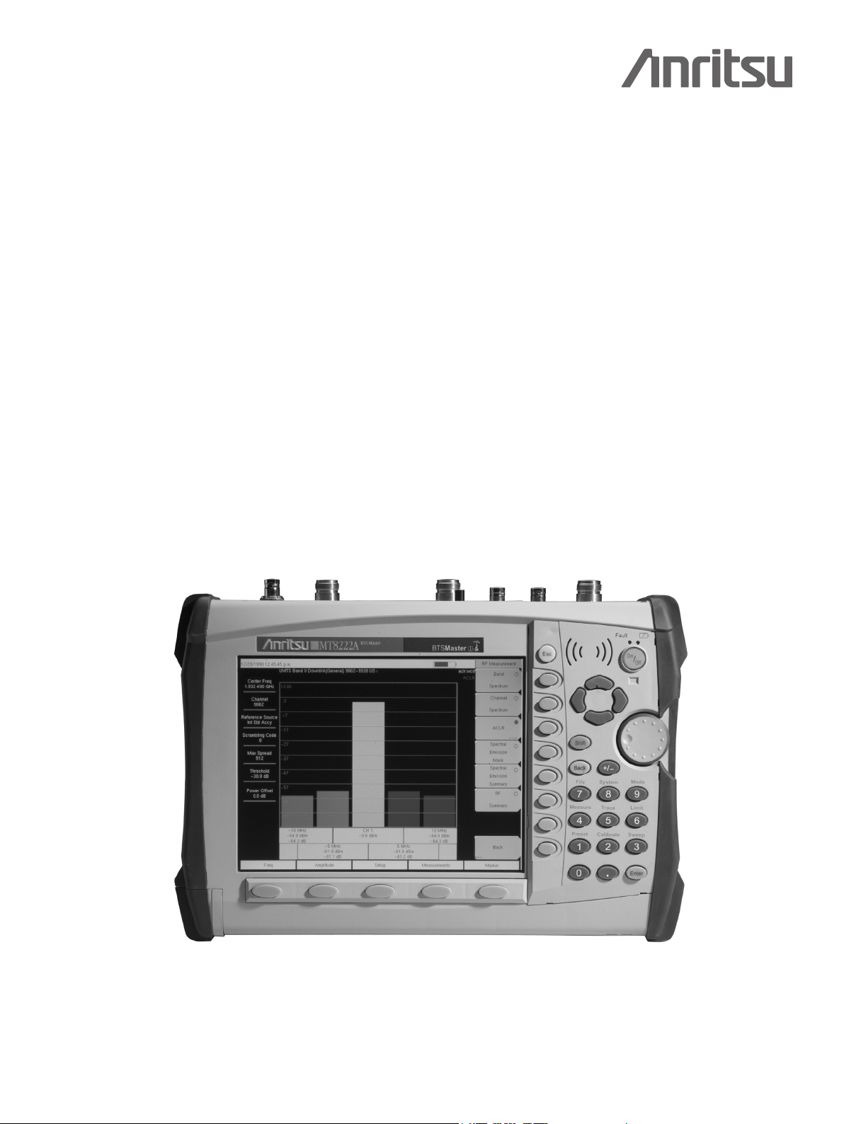
Base Station Analyzer
MT8222A
BTS Master
Introduction
High performance handheld base station analyzer with a complete set of measurement tools, spectrum analyzer, cable and
antenna analysis, power meter, Bit Error Rate Tester for communication backhaul, supports multiple modulation formats
GSM/GPRS/EDGE, W-CDMA/HSDPA, CDMA/EVDO, WiMAX 802.16d/802.16e, TD-SCDMA and GPS.
High Performance Highlights
™
• SpectrumAnalyzer100kHzto7.1GHz
• 2portCable&AntennaAnalyzer
10 MHz to 4 or 6 GHz
• HighAccuracyPowerMeter
±0.16 dB
• 4kg(9.0lbs)
• BitErrorRateTesterE1,T1&T3
• InterferenceAnalyzer
• Channelscanner
• GPSreceiveroption
• 2and2.5GmodulationoptionsGSM/
GPRS/EDGE,IS-95
• 3GModulationoptions
W-CDMA/HSDPA, 1xrtt/EVDO and
TD-SCDMA
• 3.5Gmodulationoptions802.16dand
802.16e
• 2.5–3hourbatterylife
The Anritsu MT8222A is the most advanced ultra-portable base station analyzer on the market,
featuring unparalleled performance at a modest price.

Specifications
Cable and Antenna Analyzer
Frequency Range: 10 MHz to 4 GHz
Frequency Range (Option 26):
10 MHz to 6 GHz (All other specs remain the same)
Frequency Accuracy: 25 ppm
Frequency Resolution: 10 kHz
Data Points: Low, Medium, High (137/275/551)
Interference Immunity:
On-Channel: +17 dBm
On-Frequency: 0 dBm (RF Out) +30 dBc RF in
1-Port Power: High: 0 dBm (typical)
2-Port Power:
High: 0 dBm (typical)
Low: –35 dBm (typical)
Corrected Directivity: 42 dB (10 MHz to 6 GHz)
1-Port Accuracy:
= <0.8 + 20 log (1 ±10
Directivity – Measured Return Loss
System Dynamic Range:
80 dB, 10 MHz to 3 GHz
70 dB, >3 GHz to 5.5 GHz
65 dB, >5.5 GHz to 6 GHz
Return Loss:
Range: 0 to 60 dB
Resolution: 0.01 dB
VSWR:
Range: 1 to 65
Resolution: 0.01
Cable Loss:
Range: 0 to 30 dB
Resolution: 0.01 dB
1-Port Phase:
Range: –180° to +180°
Resolution: 0.01°
Smith Chart:
Resolution: 0.01
2-Port Gain:
Range: –120 to 100 dB
Resolution: 0.01 dB
2-Port Phase:
Range: –180° to +180°
Resolution: 0.01°
Distance-to-Fault:
Fault Resolution (meters): (1.5 x 10⁸ x vp)/∆F vp is
the propagation constant and ∆F is F2-F1 in Hz
Horizontal Range (meters): 0 to (data points-1) x
Fault Resolution to a maximum of 1500m (4921 ft.)
where datapoints = 137/275/551
Vertical Range (Return Loss): 0 to 60 dB
Vertical Range (VSWR): 1 to 65
–E∆/20
) dB, typical E∆ =
Spectrum Analyzer
Frequency:
Frequency: 100 kHz to 7.1 GHz
Maximum Continuous Input: +30 dBm
Tuning Resolution: 1 Hz
Frequency Reference:
Aging: ±1 ppm/10 years
Accuracy: ±0.3 ppm (25 °C ±25 °C) + aging
Frequency Span:
10 Hz to 7.1 GHz plus 0 Hz (zero span)
Sweep Time:
Minimum 100 ms, 10 µs to 600 seconds (zero span)
Sweep Trigger: Free run, Single, Video, External
Resolution Bandwidth:
(–3 dB width) ±10%, 1 Hz to 3 MHz in
1–3 sequence 8 MHz demodulation bandwidth
Video Bandwidth:
(–3 dB) 1 Hz to 3 MHz in 1–3 sequence
SSB Phase Noise:
–100 dBc/Hz max at 10, 20 and 30 kHz offset from
carrier –102 dBc/Hz max at 100 kHz offset from carrier
Amplitude:
Measurement Range: DANL to +30 dBm
Absolute amplitude accuracy Power Levels
≥–50 dBm, ≤35 dB input attenuation,
Preamplifier Off:
100 kHz to ≤10 MHz ±1.5 dB
>10 MHz to 4 GHz ±1.25 dB
>4 GHz to 7.1 GHz ±1.75 dB
Displayed Average Noise Level
(DANL in 1 Hz RBW, 0 dB attenuation,
Reference level –50 dBm, preamp on):
Frequency Typical Max
10 MHz to 1 GHz –163 dBm –161 dBm
>1 GHz to 2.2 GHz –160 dBm –159 dBm
>2.2 GHz to 2.8 GHz –156 dBm –153 dBm
>2.8 GHz to 4.0 GHz –160 dBm –159 dBm
>4.0 GHz to 7.1 GHz –158 dBm –154 dBm
Input-Related Spurious:
(–30 dBm input, 0 dB input attenuation,
Span <1.7 GHz)
–70 dBc typical –60 dBc max*
* Exceptions:
Input Frequency Spur Level
1674 MHz –38 dBc (–48 typical)
Residual Spurious:
(Preamplifier on, RF input terminated, 0 dB input
attenuation)
–100 dBm max
(Preamplifier off, RF input terminated, 0 dB input
attenuation)
–90 dBm max**, 100 kHz to <3200 MHz
–84 dBm max**, 3200 to 7100 MHz
**Exceptions:
Frequency Max Spur Level (Typical)
250, 300, and 350 MHz –85 dBm
~4010 MHz –80 dBm (–90 dBm)
~5084 MHz –70 dBm (–83 dBm)
~5894 MHz –75 dBm (–87 dBm)
~7028 MHz –80 dBm (–92 dBm)
Display Range:
1 to 15 dB/div in 1 dB steps. Ten divisions displayed
Amplitude Units Log Scale Modes:
dBm, dBV, dBmv, dBµV
Attenuator Range: 0 to 65 dB
Attenuator Resolution: 5 dB steps
Power Meters:
Frequency Range: 10 MHz to 7.1 GHz
Display Range: –80 dBm to +80 dBm
Measurement Range: –60 dBm to +30 dBm
Offset Range: 0 to +60 dB
Accuracy:
–40 dBm <Max ≤+15 dBm:
10 MHz –4 GHz: ±1.25 dB
4 GHz –7.1 GHz: ±1.75 dB
Max> +15 dBm:
10 MHz –6.5 GHz: ±1.75 dB
6.5 GHz –7 GHz: ±2 dB
Max ≤–40 dBm:
10 MHz –4 GHz: ±1.5 dB
4 GHz –7.1 GHz: ±1.75 dB
VSWR: 1.5:1 typical
Maximum Power:
+30 dBm (1W) without external attenuator
2
W-CDMA/HSDPA
RF Measurements (Option 44)
Frequency Ranges:
Bands I - IX
RF Channel Power
(Temperature range 15º C to 35º C):
±0.7 dB typical
(±1.25 dB max)
Occupied Bandwidth Accuracy: ±100 kHz
Residual Adjacent Channel
Leakage Ratio (ACLR)1
(824 to 894 MHz, 1710 to 2170):
–54 dB typical at 5 MHz offset
–59 dB typical at 10 MHz offset
Leakage Ratio (ACLR)1 (2300-2700 MHz):
–54 dB typical at 5 MHz offset
–57 dB typical at 10 MHz offset
ACLR Accuracy (Single Channel Active)
(824 to 894 MHz, 1710 to 2170):
±0.8 dB for ACLR ≥ –45 dB at 5 MHz offset
±0.8 dB for ACLR ≥–50 dB at 10 MHz offset
ACLR Accuracy (Single Channel Active)
(2300-2700 MHz):
±1.0 dB for ACLR ≥ –45 dB at 5 MHz offset
±1.0 dB for ACLR ≥–50 dB at 10 MHz offset
Frequency Error: ±10 Hz + Time Base Error,
99% confidence level:
±10 Hz + Time Base Error, 99% confidence level
W-CDMA Demodulation
and W-CDMA/HSDPA
Demodulator (Options 45 and 65)
EVM Accuracy (824 to 894 MHz, 1710 to 2170 MHz):
(3GPP Test Model 4) ±2.5%; 6% ≤EVM ≤25%
(3GPP Test Model 5) ±2.5%; 6% ≤EVM ≤20%
(2300 MHz to 2700 MHz)
EVM Accuracy: ±2.5% for 6% ≤EVM ≤20%
Residual EVM: 2.5% typical
Code Domain Power:
±0.5 dB for code channel power >–25 dB
16, 32, 64 DCPH (test model 1)
16, 32 DCPH (test model 2, 3)
CPICH (dBm) Accuracy: ±0.8 dB typical
Scrambling Code: 3 seconds
W-CDMA/HSDPA OTA (Option 35)
Resolution: 0.1 dB
Power Monitor (Option 5)
(requires external sensor)
Display Range: –80 to +80 dBm (10 pW to 100 kW)
Measurement Range:
–40 to +20 dBm (10 nW to 40 mW)
Offset Range: 0 to +60 dB
Resolution: 0.1 dB or 0.1W
Accuracy:
±1 dB for >–40 dBm using 560-7N50 detector
Bias Tee (Option 10)
Voltage/Current:
+12 V, 250, or 500 mA steady state
+15 V, 250, or 500 mA steady state
+18 V, 350 mA steady state
+21 V, 250 mA steady state
+24 V, 250 mA steady state
1
Depends on reference level, input signal level and
single channel conditions

Interference Analyzer (Option 25)
Strength of the Interferer: Locate the Interferer
RSSI: Collect data up to 72 hours
Spectrogram: Collect data up to 72 hours
Signal ID:
Monitors one particular frequency or scan the span
and identify up to 12 signals. Identifies CDMA,
GSM and WCDMA signals with Signal-to-noise ratio
greater than 10 dB.
Channel Scanner (Option 27)
Frequency Range: 100 KHz to 7.1 GHz
Frequency Accuracy:
±10 Hz + Time base error, 99% Confidence level
Measurement Range: +20 dBm to –110 dBm
Channel Power:
100 kHz to ≤10 MHz ±1.5 dB
>10 MHz to 4 GHz ±1.25 dB
>4 GHz to 7.1 GHz ±1.75 dB
Adjacent Channel Power Accuracy: ±0.75 dB
GPS (Option 31)
GPS Location Indicator:
Latitude, Longitude and Altitude on display
Latitude, Longitude and Altitude with trace storage
GPS High Frequency Accuracy
when GPS antenna is connected:
±25 ppb with GPS ON, 3 minutes after satellite lock
Internal High Accuracy, when
GPS antenna is not connected:
Better than ±50 ppb for 3 days from a High Accuracy
GPS Lock and within 0º C to 50º C ambient temperature
GSM/GPRS/EDGE
RF Measurements (Option 40)
Occupied Bandwidth:
Bandwidth within which 99% of the power
transmitted on a single channel lies
Burst Power:
±1 dB typical for –50 dBm to +20 dBm (±1.5 dB max)
Frequency Error:
±10 Hz + time base error, 99% confidence level
GSM/GPRS/EDGE
Demodulator (Option 41)
GSMK Modulation Quality
(RMS Phase) Measurement Accuracy: ±1 deg
Residual Error (GSMK): 1 deg
8PSK Modulation Quality
(EVM) Measurement Accuracy: ±1.5%
Residual Error (8PSK): 2.5%
CDMA – RF Measurements (Option
42) and EVDO RF Measurements
(Option 62)
Channel Power Accuracy:
±1 dB typical for RF Input from +20 dBm
to –50 dBm (±1.5 dB maximum)
cdmaOne and CDMA2000 1xRTT
Demodulator (Option 43)
Residual Rho:
>0.995 typical for RF Input from +20 dBm to –50 dBm
(>0.99 dB maximum)
Rho Accuracy: ±0.005 for Rho >0.9
Frequency Error:
±10 Hz + Time base error, 99% confidence level
(in slow mode)
PN Offset: with 1 x 64 chips
Pilot Power Accuracy:
±1 dB typical, relative to Channel Power
Tau: ±0.5 µs typical (±1 µs maximum)
EVDO Demodulator (Option 63)
Demodulator Measurements are
EVDO Rev A compatible.
Residual Rho:
>0.995 typical for RF Input from +20 dBm to –50 dBm
(>0.99 dB maximum)
Rho Accuracy: ±0.01 for Rho >0.9
Frequency Error:
±20 Hz + Time base error, 99% confidence level
PN Offset: within 1 x 64 chips
Pilot Power Accuracy:
±1 dB typical relative to Channel Power
Tau: ±0.5 µs typical (±1 µs maximum)
cdmaOne and CDMA2000 1xRTT
Over The Air (Option 33) and
EVDO Over The Air (Option 34)
Over The Air Measurement:
Nine strongest pilots with Tau and Ec/Io.
Six multipaths relative to strongest pilot.
Fixed WiMAX RF Measurements
(Option 46)
Channel Power Accuracy1:
±1 dB Typical for +20 dBm to –50 dBm
(±1.5 dB max)
Fixed WiMAX Demodulator
(Option 47)
Residual EVM (rms):
3% for +20 dBm to –50 dBm (3.5% max.)
Frequency Error:
±0.1 ppm + time base error, 99% confidence level
Mobile WiMAX Specifications
Bandwidths:
3.5 MHz, 5 MHz, 7 MHz 8.75 MHz, 10 MHz
Frame Length: 5 ms, 10 ms
Zone Types: PUSC
DL-MAP Support:
Regular and Compressed Map, DIUC support
DL-MAP Auto Decoding: Convolutional Coding (CC),
Convolution Turbo Coding (CTC)
Mobile WiMAX Over the Air (OTA)
Measurements (Option 37)
Time Interval: 1 sec – 60 sec
Measurement Duration: 72 hours max
Auto Save: Yes
GPS Logging: Yes
Mobile WiMAX RF Measurements
(Option 66)
Channel Power Accuracy:
±1 dB Typical (±1.5 dB max)
for +20 dBm to –50 dBm
Mobile WiMAX Demodulator
(Option 67)
For +20 dBm to –50 dBm, Residual EVM (rms):
2.5% typical (3% max), at –50 dBm on FCH
Frequency Error:
±0.02 ppm + time base error, 99% confidence level
TD-SCDMA RF Measurements
(Option 60)
Channel Power (RRC): ±1 dB typical, 1.5 dB max
(slot power from +10 dBm to -40 dBm)
TD-SCDMA Demodulator
(Option 61)
Residual EVM (rms):
3% typical (for P-CCPCH slot, slot power >–50 dBm)
Freq Error Accuracy:
±10 Hz typical + time base error (in the presence of
a downlink slot)
Timing Error (Tau) for dominant SYNC-DL code:
±0.2 Ìs (external trigger)
Supported Modulation: QPSK
Spreading Factor: 1, 16
TD-SCDMA Over the Air (OTA)
Measurements (Option 38)
32 codes displaying Ec/Io, Tau
Frequency Error:
±0.02 ppm + time base error, 99% confidence level
T1 Bit-Error-Rate-Tester (BERT),
(Option 51)
T1 Analyzer, Fractional T1 and sub-channels
BER testing at 1.544 MB, 64, 16 and 8 kB rates
Line Coding: AMI, B8ZS
Framing Modes:
D4 (Superframe), ESF (Extended Superframe)
Connection Configurations:
Terminate: 100 Ω
Bridge: ≥1000 Ω
Monitor: Connect via 20 dB pad in DSX
Receiver Sensitivity:
Terminate: +6 dB to –36 dB
Bridge: +6 dB to –36 dB
Monitor: 20 dB flat gain
Transmit Level: 0 dB, –7.5 dB, and –15 dB Clock
Sources: External Bits Clock
Internal: 1.544 MHz ±5 ppm
Pulse Shapes: Conform to ANSI T1.403 and ITU G.703
Pattern Generation and Detection:
PRBS: 2-9, 2-11, 2-15, 2-20, 2-23
Inverted and non-inverted
QRSS, 1-in-8 (1-in-7), 2-in-8, 3-in-24,
All ones, All zeros, T1-Daly, User defined (≤32 bits)
Circuit Status Reports:
Carrier present, Frame ID and Sync.,
Pattern ID and Sync.
Alarm Detection: AIS (Blue Alarm), RAI (Yellow
Alarm)
Error Detection: Frame Bits, Bit, BER, BPV, CRC
Error Sec Error Insertion:
Bit, BPV, Framing Bits, RAI, AIS
Loopback Modes: Self loop, CSU, NIU, User defined,
In-band or Data Link
Level Measurements:
Vp-p (±5%), can also display in dBdsx
Data Log: Continuous, up to 72 hrs
T1 Frequency Measurement: ±5 ppm
DS0 Channel Access: Tone Generator
Frequency: 100 Hz to 3000 Hz
Level: –30 to 0 dBm, with 1 dB steps
VF Measurement:
Frequency: 100 Hz to 3000 Hz, ±3 Hz
Level: –40.0 to +3.0 dBm, ±0.2 dBm
Audio Monitor: Manually select channel 1 to 24
ITU G-821 Analysis:
Error seconds (ES), error free seconds (EFS), severely
errored seconds (SES), unavailable seconds (UAS),
available seconds (AS), degrade minutes (DGRM)
1
Channel power accuracy will vary with amount of data burst traffic
3
 Loading...