A3: There is a one year warranty for any manufacturing faults occurred on MP1777A.
Q4: What are the limitations that should be cautioned when using the MP1777A?
A4: Kind of always make sure the appliance is plugged into a 3 pin grounded outlet, do not remove the cabinet cover nor attempt any form of repairs without being trained to do so.
Q5: How do I configure the GPIB address for the device?
A5: The GPIB address can be configured on the Secondary system screen from the Main setup screen by moving the cursor as required.
Q6: What should be done when servicing is required on the device?
A6: The equipment should not be repaired by the user, instead reach out to Anritsu Corporation or their representative for service to be rendered.
Q7: In what ways will the MP1777A be powered?
A7: The powered cable must come from a grounded 3 pin sockets. Where that is not possible then a conversion adapter should be used to provide power as long as it’s grounded.
User Manual
Page 1
MP1777A
10
GHz
Jitter Analyzer
Remote Control
Operation Manual
Vol.
Fourth
To ensure that the equipment is used safely, read
the "For Safety" in the MP1777A 10
lyzer Operation Manual first.
Keep this manual with the equipment.
2
Edition
GHz
Jitter Ana-
APR.
2005
ANRITSU CORPORATION
Document No.:
M-W1493AE-4.0
Page 2
Safety
To prevent the risk of personal injury or loss related to equipment malfunction, Anritsu Corporation uses the following safety symbols to indicate safety-related information. Insure that you clearly understand the meanings of the
symbols
Some or all of the symbols may not be used on this equipment. In addition, when drawings are included in this
manual, labels on the equipment may not be shown on them.
BEFORE
uslng the equipment.
Symbols
Safety Symbols Used in Manual
This indicates a very dangerous procedure that could result in death or serious
DANGER
A
A
A
injury if not performed properly.
This indicates a hazardous procedure that could result in death or serious injury
not performed properly.
This indicates a hazardous procedure or danger that could result in light-to-severe
injury, or loss related to equipment malfunction, if proper precautions are not taken.
Safety Symbols Used on Equipment and/or in Manual
The followmg safety symbols are used inside or on the equipment near operation locations, andlor in manual to
provide information about safety items and operation precautions.
ings of the symbols and take the necessary precautions
This indicates a prohibited operation. The prohibited operation is indicated sym-
bolically in or near the barred circle.
BEFORE
Insure that you clearly understand the
using the equipment.
rnean-
if
This indicates an obligatory safety precaution. The obligatory operation is indi-
0
n
n
cated symbolically in or near the circle.
This indicates warning or caution. The contents are indicated symbolically in or
near the triangle.
This indicates a note. The contents are described in the box
U
These indicate that the marked part should be recycled.
MP1777A
10
GHz
Jitter Analyzer Remote Control
Operation
10 September 1998 (First Edition)
20 September 2002 (Fourth Edition)
Copyright
All rights reserved. No part of this manual may be reproduced without the prior written permission of the
publisher.
The contents
Printed in Japan
Manual
O
1998-2002, ANRITSU CORPORATION.
Vol.
2
of
this manual may be changed without prior notice.
ii
Page 3
For
Safety
1
A
or
Repair
--
WARNING
1.
ALWAYS refer to the operation manual when working near locations at
which the alert mark shown on the left is attached. If the operation, etc.,
is performed without heeding the advice in the operation manual, there
is a risk of personal injury. In addition, the equipment performance may
be reduced.
Moreover, this alert mark is sometimes used with other marks and de-
scriptions indicating other dangers.
2.
When supplying power to this equipment, connect the accessory 3-pin
If
power cord to a 3-pin grounded power outlet.
is not available, before supplying power to the equipment, use a conver-
sion adapter and ground the green wire, or connect the frame ground on
the rear panel of the equipment to ground.
grounding the equipment, there is a risk of receiving a severe or fatal
electric shock.
3.
This equipment cannot be repaired by the user. DO NOT attempt to
open the cabinet or to disassemble internal parts. Only Anritsu-trained
service personnel or staff from your sales repr.esentative with a knowledge of electrical fire and shock hazards should service this equipment.
There are high-voltage parts in this equipment presenting a risk of severe injury or fatal electric shock to untrained personnel. In addition.
there is a risk of damage to precision parts.
a grounded 3-pin outlet
If power is supplied
withcut
Falling
Over
4.
This equipment should be used in the correct position.
turned on its side, etc., it will be unstable and may be damaged if it falls
over as a result of receiving a slight mechanical shock.
If
the cabinet is
Page 4
I
For
Safety
Battery
LCD
Fluid
WARNING
5.
DO NOT short the battery terminals and never attempt to disassemble it
or dispose of it in a fire. If the battery is damaged by any of these ac-
tions, the battery fluid may leak.
This fluid is poisonous.
DO NOT touch it, ingest it, or get in your eyes. If it is accidentally ingested, spit it out immediately, rinse your mouth with water and seek
medical help. If it enters your eyes accidentally, do not rub your eyes,
irrigate them with clean running water and seek medical help. If the
liquid gets on your skin or clothes, wash it off carefully and thoroughly.
6.
This instrument uses a Liquid Crystal Display (LCD); DO NOT subject
the instrument to excessive force or drop it. If the LCD is subjected to
strong mechanical shock, it may break and liquid may leak.
This liquid is very caustic and poisonous.
A
--
-
DO NOT touch it, ingest it, or get in your eyes. If it is ingested acciden-
tally, spit it out immediately, rinse your mouth with water and seek medi-
If
cal help.
them with clean running water and seek medical help.
on your skin or clothes, wash it off carefully and thoroughly.
it enters your eyes accidentally, do not rub your eyes, irrigate
If
the liquid gets
Page 5
Changing Fuse
Cleaning
For
Safety
CAUTION
1.
Before changing the fuses, ALWAYS remove the power cord from the
poweroutlet and replace the blown fuses. ALWAYS use new fuses of
the type and rating specified on the fuse marking on the rear panel of the
cabinet.
_-A indicates a time-lag fuse
T
There is risk of receiving a fatal electric shoc~ if the fuses are replaced
with the power cord connected.
2.
Keep the power supply and cooling fan free of dust.
Clean the power inlet regularly.
pins, there is a risk of fire.
Keep the cooling fan clean so that the ventilation holes are not obstructed. If the ventilation is obstructed. the cabinet may overheat
and catch fire.
If
dust accumulates around the power
Changing memory
back-up battery
Disposing the batteries
3.
Use two or more people to lift and move this equipment. or use a trolley.
There is a risk of back injury, if this equipment is lified by one person.
4.
This equipment uses a lithium battery to back-up the memory. This battery must be replaced by a servlce engineer when it has reached the end
of its useful life; contact the Anritsu sales section or your nearest representative.
NOTE:
5.
The main unit of the MP1777A uses lithium batteries. When d~sposing of
the batteries, make sure to conform with the local regulation.
The battery used in this equ~pment has a maximum useful life
of 7 years. It should be changed before this period has
elapsed.
Page 6
Page 7
If
itt
[hi\
thz
Anritsu
t.ql!rpmtmt
aJdrc\>
In
ilc\elop\
tills iilarirul.
Corporation
:I
t;tt~it. coiitirit .-\r:r~t\u
Contact
Coqmrar~w
or-
~t\
repsc\i.nt:\:r\c\
Page 8
Notes On
-
-
Th~s product and its manuals may require an Export LicenseiApproval by
the Government of the product's country of origin for re-export from your
country.
Before re-exporting the product or manuals, please contact us to confirm
whether they are export-controlled items or not.
When you dispose of export-controlled items, the
be
needed to
purpose.
brokenlshredded so as not to be unlawfully used for military
Export
Management
products/manuals are
Trademark and Registered Trademark
Quick Basic is a registered trademark of Microsoft Corporation.
I
I
viii
Page 9
Composition
--
--
MP1777A
I
Operat~on Manual
L
---
--
of
4
the
VOL
-
I
I
VOL
--
MP1777A
1
--
2
-1
i
L
,
I
-.
Operat~on manual for the maln un~t
-
-
-
Operat~on manual for remote control
Operation Manual
-
-
--
-
-_
--
_
__
_
-2
- - -
Page 10
Table
of
Contents
For Safety
Composition of the MP1777A Operation Manual
Section 1 Outline
Interface Function
1 . 1
.
1 2 System Setup Example 1-3
Section 2 GPlB Interface 2-1
2.1 GPlB Interface Functions 2-2
2.2 Device Message List
2.3 Bus Commands 2-4
2.4 Connecting the GPlB Cable 2-5
2.5 Setting GPlB
2.6 Initializing the Device ................................................................... 2-8
The GPIB setting is performed on the Secondary system screen in the Main setup screen.
GPIB
interface:
This device incorporates the following interface functions.
Control of functions except for certain functions such as power source switch and Local
Reading of all the setup conditions and screen display.
has a connector for remote control on the back face.
The GPIB interface for this device conforms to the IEEE (Institute of Electrical and Electronic Engineers) standards, 488.1-1987. The software conforms to the standards IEEE488.2 and
Commands for Programmable Instruments). (See the Section
This device only functions as a device and does not function as a controller. Accordingly, the
following functions.
Cord
PPO
DC
GPIB lnterface Functions
Table
Interface Function
All the source handshake functions is available.
All the acceptor handshake functions is available.
Basic talker functions is available.
Serial port function is available.
Talk only mode function is available.
Talker cancellation function is bv MLA available.
Basic listener functions is available.
No listen only mode function is available.
Listener cancellation function is
All the servlce request functions is available.
All the remote and local functions
No parallel port function is available.
All the device clear functions is available.
I
All the device trigger functions is available.
No system controller functions is available.
2-1
GPIB lnterface Functions
bv
MTA available.
is
available.
IEEE488.2 Standards
Incomoration of all the functions as the standard features
Incorporation of all the functions as the standard features
The device shall incorporate one of the following subsets: TS, T6, TES or TE6.
The device shall incorporate one of the following subsets:
L3,
L4,
LE3 or LE3.
Incorporation of all the functions as the standard features
RLO (no functions) or
PPO
(no functions) or
Incorporation of all the functions as the standard features
/
DTO (no functions) or
CO (no functions).
sub-sets:
C7,
C9
C4
or C
RLI
(all functions)
PPI
(all functions)
DT1
(all functions)
and
C5,
1
1.
or one of the following
GPIB
interface has the
Page 19
2.2
Device
Message
List
2.2
I)<\
hu\
r-c\po~i\e me\\age\.
1'11~
\LI;C\
I':.cyrxn x~il re\ponw lile\\:ige\ :ire further cla\\lfied Into the fc~llo\i
See the Stx,t~on 7 !'or 111c)re ~nft?rrilatior;.
(~'oriinion
(See the Sectii>r~ 5 "Si:\tu\ Repor\" for iticvc intor
rl1~lllt~Il.
IEEE48X.2
1
Message
ri~oile
(~i
liv~l the
.IK
;\SC'II d,ita rne\\;ige\ tr-an\fcrreil fron~ the controller
t~-;~ri\t~r~ecl from the tlevlce to the conlrollcr.
:\I
U
Iirii'
Table
List
i\
\et
31
2-2
"H"
Device Message
Program Message
4
for more information.)
10
the ile\ i~.e
1
CL)IIIII~;II~~\
).
:md
art. ci:tsaified
111s
ille\hapc typcs.
List
(See the Section
Statu\ rrle\\agc\
(See the Sectic~n
Kc\ponw n!t.\sagc\
Into
t\vo t!peh. the proyrmi rrlt.sqe\ arid
ti:
the
tic\
lcc, \+I~llc the re\;>oriw rn~~v
Response Message
5
for more information.)
(3
"SCPI
Outlinc' for
111111.2
\\
her1 the
irifor7n;1[1o1i
)
I
I
I
I
-
-
tt?===d
-
ry
r.3
I
<--PI
Program
n
messace
Responce message
I
Fi6.
2-1
Device
i'he mei\;tgcL; rllt:~it~oried :iho\e are t'\~hali~~~l thro~lg.h thc
h~net' de\crip~~uri ot ~iie IT) b~ift~r.
Table
2-3
rput
.\
f
IF0
I
~-IS\[
(11
~.'II-\I
OLI!)
suffer
type
ri;eri~rr>
AYC;I
111
[CII~~O-
Message
110
hut'kr- i:f tht. de\,ice. The follc)\+ing xx.[lori pro\ i..!c\
I:0
Buffer
I
I
.,\
f.il.0
!ypt,
Output Queue
siie!~~(.>i.>
:ir.~:t
for
--
[lie
C\:.~LI~~.
:\\I
ill?
.I
L>-\L3',
Page 20
Section 2 GPIB Interface
2.3
Bus commands refer to internal interface communications exchanged when the bus is set to the command mode (when the
ATM
DCL (Device clear)
SDC (Selected Device Clear) Initializes the exchange of messages among addressed devices. The operations are
GET (Group Execute Trigger)
IFC (Interface Clear) Init~allzes the ~nterface.
Bus
line is set at
Bus Command Operations
Commands
"L").
The table below shows a list of bus commands.
Table
2-4
Details of Bus Commands
Initializes the exchange of messages among all the devices connected to the
bus.
the same as those for DCL.
Performs the same operations as those triggered when the
GPIB
Start/Stop key is pressed
Page 21
2.4
Connecting
the
GPIB
Cable
2.4
Connecting
the
GPIB
Ca
Fig.
2-2
Sketch
of
GPlB
Cabi2
Page 22
Section
2
GPlB
Interface
2.5
To use
front panel.
Perform the setting shown above on the Secondary system screen in the hhin setup screen.
(1)
Setting GPlB
GPIB
as a remote interface, set the device to the local mode and set the address by performing key input on the
Table
Details of Setting
Address setting
(a) Pressing the Setup key causes the Main setup screen to open.
The Main setup screen has "Setup" indicated on the left top section of the screen.
Setu~
I
Bit
Rate
Jitter Setting:
2-5
I
Interface
Equalizer
Details
Setting Item
Address
1
ITx&Rxl Time
of
Setting when GPlB lnterface is Used
[
2,488
M
]
[
OFF
]
Setting Range
XX : XX : XX XWXXWXX
0
to
30
[
Clock
Fig.
(b) Moving the cursor to the shaded section of the figure above and pressing the Setup key causes a window as
shown below to open. To select the Secondary system screen, move the cursor onto "System" using the cursor
key and press the Set key.
Internal
2-3
Main setup Screen
]
Fig.
2-4
Screen Selection Window
Page 23
2.5
Setting
GPlB
Setup
Buzzer
Date & Time
--
-
Address
Fig.
System
[
adjust
[
00
1
2-5
Secondary System Screen (When
:
11
.
-
OFF
:
17
01iJan195
GPlB
Interface
1
]
is
Used)
Page 24
Section
2
GPIB
Interface
2.6
IEEE488.2
Level Type of Initialization
Initializing
st~pulates three levels of system initialization: initialization of the bus, message and device.
1
Initialization of the bus Initializes the functions of all the interfaces connected to the bus with the IFC
2
Initialization of the message Disables the function to report to the controller that the initialization of the
3
Initialization of the device Returns the device to the original state unique to the device by *RST, regard-
the
Table
Device
2-6
Types of System lnitialization
Outline
message from the controller.
exchange of messages among all the devices on GPIB and relevant operations
are
completed by
ization of the exchange of messages among specified devices on GPIB and
relevant operations are completed by SCL, also one of the GPIB bus com-
mands.
less of the status during past usage.
DCL,
one
of
the
GPIB
bus commands, and that the initial-
2.6.1 lnitializing the Bus
IFC:
Function:
Initialization of the bus by the IFC statement
Switches the IFC line into an active state for about
devices connected to the GPIB bus line. IFC can be transmitted only by the system controller.
2.6.2 lnitializing the Message
DC'L and
Functions:
SDC:
Initialization of the exchange of messages by the DCL and SDC bus commands
Initializes the exchange of messages for all the devices on GPIB or specified devices on GPIR.
Initialization of the message exchange is aimed at setting preparations to enable the controller to send
new instructions in the event that sections related to the message exchange in devices are set in a state
inappropriate for the control to be executed from the controller because, for example, other programs
were executed earlier, although changing the panel setting is not required.
DCL:
SDC:
Initializes the message exchange among all the devices on GPIB
Initializes the message exchange among specified devices.
100
ps and initializes the interface function of all the
Page 25
2.6
Initializing
the
Device
2.6.3
,KS'I':
2.6.4
Initializing
Inrti,il~zat~m
Device
Status
the
of
Device
the de\
ici.
b>
tlic
.KS1
at
Power Activation
cornril,inci
Page 26
Section 2 GPIB Interface
Page 27
ection
3
Listener
Input
Format
3.1 Listener Input Program Message
3.2 Functional Elements of Program Message
3.2.1 <TERMINATED PROGRAM MESSAGE>
3.2.2 iPFiOGRAM MESSAGE TERMINATOR>
3.2.3
3.2.4 <PROGRAM MESSAGE>
3.2.5 <PROGRAM MESSAGE UNIT SEPARATOR>
3.2.6 <PROGRAM MESSAGE UNIT>
3.2.7
3.2.8
3.2.9 <QUERY PROGRAM HEADER>
3.2.1
3.2.1
3.3 Program Data Format
3.3.1 <CHARACTER PROGRAM DATA>
3.3.2 <DECIMAL NUMERIC PROGHAM DATA>
3.3.3 <BOOLEAN PROGRAM DATA>
3.3.4 <STRING PROGRAM DATA>
<white
<COMMAND MESSAGE
<COMMAND PROGRAM HEADER>
0
<PROGRAM HEADER SEPARATOR>
1
<PROGRAM DATA SEPARATOR>
space>
.........................
....................
Format
.................................................
UNIT>
........................................
......................................
..............
..........................................
and
<QUERY
.......................................
..
.....
..
........................................
..................................
...........................
..........................
..............................
..................
MESSAGE
..................................
...............................
..................................
.....................................
...................................
.........................
UNIT>
....
..
....
3-2
3-4
3-4
3-5
3-5
3-6
3-7
3-7
3-8
3-10
3-12
3-13
3-13
3-14
2-15
3-16
3-17
3-17
Page 28
Section 3 Listener lnput Format
3.1
The following section shows program messages when, for example,
reception signal is set to
The program message format comprises a sequence of functional elements divided into the units of minimum level to
(
<
and
express functions. The uppercase letters in angled brackets
elements. The functional elements are further divided into elements called the coding elements. The lowercase letters in
(
<
and
>
)
angled brackets
The following pages provide explanations of the program message format using the functional syntax diagram and coding
syntax diagram.
Functional syntax diagram: Graphic representation of selection of functional elements along specific routes
-
Coding syntax
diagram:
in the figure above show examples of coding elements.
Graphic representation of selection of coding elements along specific routes
> ) in the figure above show examples of functional
Page 29
1
hi.
URI
I
F*
~r:d
Kf
.\I>
io11111i~nt1~
t~kc
the
tolloutng
forrn,~tj
3.1
Listener
Input
Program
Message
Format
pp
WRITE
-.
@
pppp-
Outputs data to the devlce
MFormat
WRITE
@
--
Dev~ce number Data
-
Data-+; Arithmetic expression
1
Charxter string expression
~
..
~
.---p---------pp--.-.pp
<Example> The same as the example given on the previous page.
WRITE
@03
-
-.--
A
:
":
SENS : TEL
:
RANG
U14
:
:
SENS : TEL : BRAT
Listener address
READ
iin case that the GPlB address of the
@
10
GHz
J~tter Analyzer is set at
Subst~tutes the data Input froin the dev~ce to the var~dble
--
--
-
-
-
IFormat
-
-pp--p
READ @Dev~ce number Vanable
-
--
I
M9953"
3)
--
<Example> Substitutes the data input from the device (input tangent~al line setting)
to the variable,
WRITE @03 : ":
READ 003
A$.
SENS : TEL : RANG?" t Inquires about the input
:
A$
i
tangential line setting.
Listxer address
(irl
case that the GPlB address of the
10
G!iz Jitter Analyzer is set at
3)
Page 30
Section 3 Listener Input Format
3.2
This measuring instrument accepts the program message
message. The following section explains each functional element of the program message.
3.2.1
The <TERMINATED PROGRAM MESSAGE> is defined as follows.
The <TERMINATED PROGRAM MESSAGE> constitutes a data message that incorporates all the functional elements
necessary for the controller to send data. to this measuring instrument.
To complete the transfer of the <PROGRAM MESSAGE>, the <PROGRAM MESSAGE TERMINATOR> is added
the end of the <PROGRAM MESSAGE>.
Functional Elements
<TERMINATED PROGRAM MESSAGE>
<PROGRAM MESSAGE>
Refer
to
-
of
3.2.4
Program Message
by
detecting the terminator located at the end of the program
MESSAGE
Refer to
3.2.2
to
*ddreSS
Listener
(device)
Example: <TERMIN.ATED PROGRAM MESSAGE> to send two instructions
3
Listener address spec~l~cat~on
-I
<TERMINATED PROGRAM MESSAGE,
<PROGRAM MESSAGE, <PROGRAM MESSAGE TERMINATOR,
A
A
Y
,
Talker
;---<
Functional elements
Page 31
3.2
Functional
Elements
of Program Message
<PROGRAM
I
--
<wh~te space>
7-
MESSAGE
Refer
to
3
231
TERMINATOR>
I--
(
Page 32
Section 3 Listener Input Format
The <PROGRAM MESSAGE>
is
defined as follows.
SEPARATOR>
Refer
to 3.2.5
I
<PROGRAM MESSAGE UNIT>
Refer
to
3.2.6
The <PROGRAM MESSAGE> is composed of a sequence of zero, one or multiple <PROGRAM MESSAGE UNIT>
elements.
The <PROGRAM MESSAGE UNIT> elements signify programming instructions or data to
this measuring instrument. The <PROGRAM MESSAGE
multiple <PROGRAM MESSAGE UNIT> elements.
Example: Selects the reception jitter range
UNIT
of4
SEPARATOR> is used as the separator for delimitting
CTZ
and sets the reception signal to
I
*
be
sent from the controller to
9953M.
,
:
SENS : TEL : RANG
<PROGRAM MESSAGE
/
<PROGRAM MESSAGE
UNIT>
<PROGRAM MESSAGE,
:
:
U14
SENS : TEL : BRAT
I
UNIT
SEPARATOR>
M9953
<PROGRAM MESSAGE UNIT>
Page 33
3.2
Functional Elements
of
Program Message
3.2.5
The
in
<PROGRAM MESSAGE
h~te
\pace>
I\
defined
.
a\
--
tollou
s.
.
-
--C?
UNIT
<wh~te
character>
SEPARATOR>
space
Lp
*
3.2.6
<PROGRAM
MESSAGE
/-*
I
\
--
<QUERY MESSAGE
C
UNIT>
Refer
to
Refer
to
3
3
2
2
7
---_I
UNIT2
7
7)
-2
I
d
Page 34
Section 3 Listener Input Format
3.2.7
(1)
<COMMAND MESSAGE
The <COMMAND MESSAGE UNIT>
UNIT>
is
defined
Example: Sets the data.
as
follows.
and
<PROGRAM DATA,
-
:
SYST
:
DATE
1993,7,15
<QUERY MESSAGE
UNIT>
I
,,/.f
/.I
<COMMAND PROGRAM HEADER,
\
<PROGRAM HEADER SEPARATOR>
\\
<PROGRAM DATA SEPARATOR,
Page 35
3.2
Functional
I
-
-
.
<QUERY
-I
PROGRAM
HEADER>
Refer
to
3
\
+-----h
I
2
9,
\
.
-
'
<PROGRAM
HEADER
SEPARATOR>
,Refer
to
3
.
2
-
lo,,
,
I
-----*Y
Elements
-----
/<F~OGRAM
of Program
.
.
'
DATA
SEPARATOR>
'
Refer
to
3
2
11
.
--
--
-
-
<PROGRAM DATA>
L
,
--
'*
,
-----
-A
Message
-
CALC : TGR : DATA?
--
4
--
1995, 3,27,12.54
A
hb
L
4
Page 36
Section 3 Listener Input Format
3.2.8
The
The <while space> can be placed before each header.
(1)
<COMMAND
<COMMAND
The <Instrument-Control Headers are defined as follows.
PROGRAM HEADER> is defined as follows.
--
PROGRAM
<white space>
Refer to
3.2.3
HEADER>
<short form
\
I
\--I
<Instrument-
Control Headers>
-
Refer to
/
<common command
program headers
I
Refer
to
(1)
(2)
of
of
3.2.8
3.2.8
---
/
I--
/
1
<long form
Y
(2)
The <common command program header> is defined as follows.
(3)
The <program mnemonic>
<upper/lower
case aloha>
is
mnemonic>
defined as follows.
1
<program mnemonic>
to
(3)
of
Refer
<upper/lower
case alpha>
3.2.8
w
Page 37
3.2
Functional
Elements
of
Program
Message
3.2.8.1
<COMMAND
PROGRAM
HEADER>
Page 38
Section 3 Listener Input Format
3.2.9
The <QUERY PROGRAM HEADER> is defined as follows.
The <white space> can be placed before each header.
<QUERY PROGRAM HEADER>
<white space>
Refer to
3.2.3
-
\
1
(1)
The <Instrument-Control Headers> are defined as follows.
<short form
<Instrument-
Control Headers>
-
(1)
Refer to
1
<common command
program header>
1
Refer to (2) of 3.2.9
of 3.2.9
---,
1
6
1
<long form
mnemonic>
(2)
The <common query program header> is defined as follows.
<program mnemonic>
Refer to (3) of 3.2.8
*
3.2.9.1 <QUERY PROGRAM HEADER>
The <QUERY PROGRAM HEADER> is a query command, that the controller preliminarily sends to this measuring
instrument so that the controller will be able to receive the response message from this measuring instrument.
It is always characterized by the addition of the query indicator, or a question mark
The <QUERY PROGRAM HEADER> format mentioned above comes with the query indicator, or a questlon mark
added to the end
As other features are the same as those for the <COMMAND PROGRAM HEADER>, see the Section
MAND PROGRAM HEADER>" for more information.
of
the header
(
?
),
to the end of the header.
3.2.8
(
?
),
"<COM-
Page 39
3.2
Functional Elements
of
Program Message
3.2.1
1
<PROGRAM DATA SEPARATOR>
--
-
Refer
to
3.2
3
-
-
7
:
SYST
:
DATE
4
-
r
PAL4
L
-A
A
4
1993,7,15
b
-
-
,
3,"-
'7
---C
'
Refer
to
3.2.3
-
I
7-----
(
Page 40
Section 3 Listener Input Format
3.3
This section provides explanations of the format of <PROGRAM DATA> illustrated by the functional syntax diagram of
the Section
gram messages terminated as mentioned in the earlier sections.
The functional elements of <PROGRAM DATA> are used to transfer parameters of various types related to the program
header. The sections shaded in the figure below are the program data used by this measuring instrument.
Program
3.2.7
"<COMMAND MESSAGE
Data
PROGRAM DATA>
Refer
Format
to
3.3.1
UNIT>
and <QUERY MESSAGE UNIT>" from among formats of pro-
\
\I
<NON-DECIMAL
NUMERIC
PROGRAM DATA>
PROGRAM DATA>
Refer
to
3.3.3
BLOCK
PROGRAM DATA>
Page 41
3.3
Program
Data
Format
I
SENSe
-
.
fvlEASure
.
TYPE
<program mneinonm
C
Refer to
(31
of
3
2.8
SlNGle (Mnemon~c: data
to
express s~ngle measurement)
Page 42
Section 3 Listener Input Format
3.3.2
The
(I)
<DECIMAL NUMERIC PROGRAM
<DECIMAL NUMERIC PROGRAM DATA>
The
<mantissa> is defined as follows.
DATA>
expresses a numeric value
of
a decimal digit and is defined as follows.
(2)
The <exponent> is defined as follows.
This measuring instrument uses the integer type of decimal digits.
Integer type
Expresses the integer values of decimal digits. The underline
Zero
(0)
enabled to be input
Space between a sign and digit disabled
Space enabled to
The plus sign can be either added or omitted
The figure below shows responses to the query for the selection of the receiving jitter range, : SENS
to the query for the sign speed of the received signal,
As the SCPI response has
Talker
Output
no
header, the response only consists of data.
Response Message
:
SENS : TEL : BRAT?.
<TERMINATED RESPONSE MESSAGE,
<RESPONSE MESSAGE> <RESPONSE MESSAGE TERMINATOR,
Format
-
Listener
(device)
<RESPONSE MESSAGE UNIT> <RESPONSE MESSAGE UNIT SEPARATOR> <RESPONSE MESSAGE UNIT>
U14
U14
;
M9953
r~---
I
I----
9
<NL>
1..
1
M9953
:
TEL
<NL>
:
RANG?,
Address
(controller)
3
Talker
t
and
cnrl numerlc response data>
Like the program message, the response message format comprises a sequence of functional elements divided into the
units of minimum level to express functions. The uppercase letters in angled brackets
examples of functional elements. The functional elements are further divided into elements called the coding elements.
The lowercase letters in angled brackets
ingly, the same syntactical notational convention is used for the talker and the listener.
(
<
and
>
)
in the same figure above show examples of coding elements. Accord-
<character response
(
<
and
data,
>
)
in the figure above show
Page 47
4.2
Functional Elements
of
Response
Message
4.2
4.2.1
llic
--TI
Functional Elements
of
Response Message
<TERMINATED RESPONSE MESSAGE>
KhIIh
11
PI)
KL
4POh\I kI1-54
I
<RESPONSE MESSAGE>
4
IGF>
Refer
1s
dztlned ,i\
to
4.2
3
folio\\\
.
-
-
--
----+
MESSAGE
TERMINATOH>
Ltsteier
idevlce)
L--
\
1
__A
Esiirnple: Itldicates
--
-
'
.
1111
exi~mple
of
tltc
U14
;
M9953 cNL>
-1
\
I
\
I
--
I
Functional elements
program to
\
reed
the'
-
-
I
_
state
--
_
-
7
I
of
rrceiving,jitter range currently set.
_
_
--
-d
Talker
(coi7troller)
-
--
Page 48
Section 4 Talker Output Format
The <RESPONSE MESSAGE>
is
defined as follows.
MESSAGE UNlT
/
<RESPONSE MESSAGE
The <RESPONSE MESSAGE> is composed
ments
The <RESPONSE MESSAGE UNIT> element signifies a single message to be sent from this measuring instrument to the
controller. The <RESPONSE MESSAGE UNIT SEPARATOR> element
<RESPONSE MESSAGE UNIT> elements.
the
Indicates responses to queries for
selection of receiving jitter range and for the setting of sign speed of received signal.
SEPARATOR>
UNIT>
Refer
to
4.2.5
of
a sequence of one or multiple <RESPONSE MESSAGE UNIT> ele-
is
used as the separator to delimit multiple
Example:
\
-
<RESPONSE MESSAGE
4.2.4
The <RESPONSE MESSAGE UNIT SEPARATOR> is defined as follows.
The <RESPONSE MESSAGE SEPARATOR> separates with a
SEPARARATOR>, the <RESPONSE MESSAGE UNIT> elements when a sequence of multiple <RESPONSE MES-
SAGE
<RESPONSE MESSAGE UNlT SEPARATOR>
UNIT> elements is output as one <RESPONSE MESSAGE>.
UNIT>
<RESPONSE MESSAGE
1
<RESPONSE MESSAGE UNIT,
UNlT
SEPARATOR>
semicolon
(
;
)
that constitutes the <UNIT
Page 49
4.2
Functional Elements of Response Message
4.2.5
4.2.6
<RESPONSE MESSAGE
--
.
---*
I
I
--
1
UNIT>
,,I
'
<RESPONSE
SEPARATOR>
.,
Refer
--,
<RESPONSE DATA>
Refer
DATA
to
--/I
to
--.
4
3
2.6
2
7
<RESPONSE DATA SEPARATOR>
-
,
1
u
I
I
I
-.
d
Page 50
Section
4
Talker
Output Format
4.2.7
The shaded sections in the figure below refer to the
The response data to be returned depends on the query message.
The table below lists common IEEE488.2 commands supported by this device.
Table
List of Common IEEE488.2 Commands
5-1
Mnemonic Description
*IDN? Identification Query
*OPC Operation Con~plete Command
*OPC? Operation Complete Query
*WAI Wait Continue Command
*CLS Clear Status Command
*ESE
*ESE? Standard Event Status Enable Query
*ESR? Standard Event Status Register Querq
--
--
-
-SRE Servlce Request Enable Command
Standard Event Status Enable Command
-
*SRE? Service Request Enable Query
*STB? Read Status Byte Query
*PSC Power On Status Clear Command
*PSC?
*
SAV Save Command
Power On Status Clear Query
*RCL Recall Command
--
--
-
*OPT? Option Ident~ficat~on Query
Page 53
.
IDN?
Identification Query
5.1
Common
IEEE488.2
<:'IKBITRAKL'
<Nme
111
th~\ de\~ce: ANKITSV.
f-urict~o~l
.OPC
I~~u~icti(jn
Ii\:\rllpI~' ot
llS?
OPC?
Kcports data iricl~~ding the name
Operation Complete Command
Set\ the h~r
ON
\\
->
.
l<(-.I.
Operation Complete Query
Kr\pori\e cYKI
.-'iSC'II
RESl'ONStr.
of
product ni:tri~~f:~cturt'r>.
MP1777.4.
0
thlt to end oper~~tio~i\)
hen the e\ecutlcili
I
.
.
OP('
YL
2ILRIC
of
tlir
--
KE5PO\\I
L):\?.A>
4lodCl
of
product rnariufxt~rrer 2nd ~nc~dcl ~i;inie
pre\
IOU\
I)
'il
name>. <Scr~al
0.
01
c)t
the \r:~nd:ird e\ent .;t;trus seg~\tzl arid
r~l\t~xct~ori
I\
No.>.
i~ornplcteii.
\>
<k'rrriluare Ke\.~slon
itcht.\
Yo.>
SRQ
WAI Wait Continue Command
Keep\
the ~.urilrlleiiccrricr1t
ot
the pre\ lou~ rnrr-uctiun
I
t:\ccu!r\ the o\crl:q7 co~iin1;11xl
Till\ f~~nct~o~i
I
eflc<ti\c
01-
I\
01i1!
the ekecution
of
thc
11t'kt
~ii\trt~il~~~i on hold
conipleted.
;I\
thc e~~uer~t1;11 co~ii~~i;~ri~i.
for the prevlou\ irl\t:-~~c!iim.
~~rltil
ill?
cxreutlc'ri
j
Page 54
Section 5 Common
IEEE488.2
Commands
*CLS Clear Status Command
Parameter None
Function
Example of use
-ESE
Parameter <DECIMAL NUMERIC PROGRAM DATA>
Function
Example of use
Clears all the status composition excluding the output queue and MAV summary message
However, the enable register and Transition filter are not cleared.
Clears both the output queue and MAV bit when
GRAM MESSAGE TERMINATOR>, and at the same time, before the <Query MESSAGE
UNIT> element.
>
*CLS
Standard Event Status Enable Command
0
and
Integer value between
Set as the parameter the sum total of the bits desired to be enabled among the standard event
status enable register.
Set
1
for enable and 0 for disable.
See the Section for the "Status Byte" for the composition of the register of this device.
Sets and clears the standard event status enable register.
Sets bits
>
*ESE
2
and 4 of the standard event status enable register.
20
255.
*CLS
is
sent immediately after
the
<PRO-
*ESR?
Response
Function
Example of use
Standard Event Status Register Query
<NU
1
NUMERIC RESPONSE DATA>
Integer value between
Set
as
the response the sum total of the bita of the standard event status register.
See the Section for the "Status Byte" for the composition of the register of this device.
Inquires about the current value
When a command error is found.
>
*ESR?
<
32
0
and
255.
of
the standard event status registel
Page 55
5.1
Common
IEEE488.2
sSRE
Service
fJ,~rmetcr ti11 CIhl
enable regi\tcr.
Set
1
for
See the Srct~or~
Service Request
<NK
I
SI'\!I-:[.11C' RESPONSE
Inte~cr \:iiu~ bct~rei~
Set
;I\
tl~e ~t'~,pcvl\c the
See the St'ctioi:
Request
\I
\,LI"LII.
enable
anti 0 for di\ahls.
for
for
Enable Command
IKIC
I'KO(iK4M
the "Statu\
Enable
0
kunl
the "S~a~us H~rc'
Bg
te" for the cori:po\itiori
Query
UA
I,:\>
;IIIC~
255,
total ot'thr b~t\
for
L14 1A>
ot
of
tht.
the cornpo\~tio~~
ice er~;~ble reglst'r.
ot
the reyi\ter ot't111\ de\ ice
the regI\tt'r
ot
[hi,
dr:\
ice
STB? Read Status Byte Query
Inquires nhout the curl-ent v:~lue
rriq
Statu\ I hit.
of
the \t:ttus
b>
tc
regi\ti.r ir~clud~ng the 1lSS (M,~\ter Sun-
Page 56
Section 5 Common
*
PSC Power On Status Clear Command
IEEE488.2
Commands
Parameter
Function
Example of use
*PSC?
Response
Function
<DECIMAL NUMERIC PROGRAM DATA>
O
...................
1
...................
Determines whether or not to clear each enable register of the service request, standard event
status and parallel poll of the status report module when the power is switched
When the mode is set to
generate SRQ after the power source is turned ON.
When the mode is set to
generate SRQ after the power source is turned ON.
Generates SRQ without clearing the power ON status flag.
>
vPSC
Power
<NR1 NUMERIC RESPONSE DATA>
0
...................
1
...................
Inquires about the truth or falsity of the power
Sets the power ON status clear flag to false.
Sets the power ON status clear flag to true.
0.
the enable register will not be cleared and the device is enabled to
1,
the enable register will be cleared and the device is disabled to
0
;
*SRE
32
;
*ESE
128
On
Status
Clear
Query
Sets the power ON status clear flag to false.
Sets the power ON status clear flag to true.
ON
status clear flag.
ON.
Example of use
*
SAV
Parameter
Function
Example of use
2
*PSC?
<
0
Save
Command
<DECIMAL NUMERIC PROGRAM DATA>
1
to 10
.........
4-4
Writes the current device setting into the memory of specified number.
7-
1
There is no limit to the state to be saved. See the Table
As an SCPI command that has the same function,
able.
Writes the current setting into the memory number
z
-SAV
1
:
SYSTem : MEMory : STORe is avail-
1.
in the Section
7.5
"Parameter".
Page 57
5.1
Common
IEEE488.2
*RCL Recall Command
Parameter <DECIMAL NUMERIC PROGRAM DATA>
0 to 10
Function Calls the memory of a specified number and, by doing so, returns the device to the previous
state.
There is no limit to the state to be loaded. See the Table 7-1 in the Section 7.5 "Parameter".
As an SCPI command which has the same function,
:
SYSTem : MEMory : RECall is avail-
able.
1
Example of use
Calls the information stored in memory number
>
*RCL 1
and performs setting.
*OPT? Option Identification
Response
<ARBITRARY ASCII RESPONSE DATA>
Characters to correspond to the option or unit
Interface (Bit Rate) selection condition option
Standard
l
2,488 M, 4,977 M. 9,953
Interface (Bit Rate) selection condition option
Option 0
Reports on options and units mounted all delimited by a comma.
Options
>
<
.OPT?
OPT1
01
and 02 are mounted.
,
OPT2
Page 58
Section 5 Common
IEEE488.2
Commands
Element
(
I
)
CHARACTER
RESPONSE DATA
Example:
ABC
DEFG
(2)
NR 1 NUMENIC
RESPONSE DATA
Example:
123
+I23
-1233
(3) NR2 NUMENIC
RESPONSE DATA
Example:
12.3
+12.34
-12.345
Function
Expresses short mriemonic data.
Expresses integer values of decimal digits.
Expresses fixed point numerical values.
(4) NR3 NUMENIC
RESPONSE DATA
Example:
1.23E+35
-12.3E+45
Expresses real numbers
of
declmdl dlg~ts w~th exponent.
Page 59
Element
(5)
STRING
RESPONSE DATA
Example:
"1233"
"ABCD"
"
1234.5"
(6)
ARBITARY ASCII
RESPONSE DATA
Example:
<ASCII> <ASCII
Byte>
NLAEND
--
Function
Expresses a character string in double quotations
/
quote char>
Sends
ASCII
data bytes excluding the
NLAEND
son,
minated without an exit point.
An example of using the
(or
u
NL
only) is placed next to the last data, and the data
GPIB
<ASCII
data byte>
NL
character without delimiting them. For this rea-
interface is shown below.
/
(").
5.1
1
Common
I
i,
accordingly ter-
IEEE488.2
Page 60
Section 5 Common
IEEE488.2
Commands
Page 61
Section
The configuration of the status registers of the MP1777A conforms to the SCPI stipulations. (SCPI: Standard Command
for Programmable Instruments, see the Section 7 for more information.)
This section provides descriptions of the configuration of status registers and definition of the status register bit specific
to the device.
6
Status Report
6.1 Configuration of MP1777A Status Registers
6.2 Status Registers Specified
6.3
Status Register Specified
6.4 Status Register Specific to MP1777A
6.5
Reading, Writing and Clearing Status Registers
by
IEEE488.2 6-4
by
SCPl
........................................
.................................................
..........................................
...................................
.............................
6-2
6-6
6-7
6-8
Page 62
Section 6 Status Report
6.1
SCPI stipulates that the status register configuration must conform to the configuration specified by
incorporate the SCPI OPERation status register and QUEStionable status register specific to SCPI.
The figure below shows
position and width to be provided later)
Configuration of MP1777A Status Registers
a
simple block diagram of status registers mounted on this device. (Explanations of the bit
..................
Errorlevent aueue
Output queue
status register
OPERation
status register
7
-
-
-
-
4
Ll
IEEE488.2
and
Standard even1
:
status register
i:*
Fig.
6-1
Block
Registers specified by
Register specified by SCPI is OPERation status register.
Device-specific register is
IEEE488.2
INSTrument status register.
are event register and status byte register.
Diagram of Status Registers
Status byte
IEEE
488.2
stipulations
SCPI stipulations
.................
1
Page 63
6.1 Configuration of MP1777A Status Registers
Status registers excluding the registers specified by
IEEE488.2
are configured
Condition Transition Event Event enable
register filter register register
. .
.
.
Fig. 6-2 Block Diagram of each Status Register
Table 6-1
Definitions of Register and Filter
Register and Filter Definition
Condition register
Monitors the device status and performs real-time change in accordance with the device
status.
For this reason, this register does not store the status.
as
follows.
-
Summary Message
Transition filter
Event register
Event enable register
Sets the condition register details to the event register
The transition filter comes in three modes, depending on the changes of the condition register to be evaluated.
Positive direction change: The event becomes true only when the corresponding condition
changes from false to true.
Negative direction change: The event becomes true only when the corresponding condition
changes from true to false
Both direction change:
Stores the output of the transition filter.
Selects the bit of
corresponding
The event becomes true when
negative direction takes place.
Event Reg~ster to trigger a sh~ft of summary message to true.
a
change into the positive or
Page 64
Section 6 Status Report
6.2
IEEE488.2
Status byte register
Standard event status register
Standard event status Standard event
Status Registers Specified
specifies the two status registers shown below.
Table 6-2 Definitions of Status Registers Specified by IEEE488.2
Status Register Definition
A
register to set RQS and seven summary message bits.
Being used in combination with the service request enable register, this register sets
SQR ON when the logical OR of the two is not zero. RQS is system reserved in bit
and this bit reports to the external controller the presence of service request.
Sets eight types of events the device will encounter as standard events.
The log~cal OR output bit is summarized and displayed in bit
-
-@+-
----
ESB
1
register as' the
enable register status register
1
-
2 .2
by
IEEE488.2
(Event Status Bit) summary message.
OPC
NOT USED
QYE
DDE
EXE
CME
NOT
USED
PON
5
of the status byte
Errorlevent queue
I
6
Service request Status byte
enable register
-
jO/
1
-
2
-
3
-
4
-
5. ---5
-
. .
. .
. . . .
. . . . .
Logical OR
. . . . . . . .
. .
. . . . . .
. . . . .
. . . . . . .
. .
. . . .
-
-
. .
. . . . . . . .
register
-
NOTUSED
2
QUE
3
QUES
ESB
Service Request
Generation
Output queue
1
1
..
....
F
status register
OPERation
status register
Page 65
6.2
Status Registers
Specified
by
The tables below show the definition
Table
of
register bit specified by
6-3
Definition of Status Byte Register Bit
IEEE488.2.
Bit Status Byte Register Definition
DB2 QUE (ErrorEvent QUEue) Indicates that the error and event queues are not empty.
DB4 MAV (Massege Available) Indicates that the output queue is not empty.
DB5 ESB (Event Summary Bit) Standard event status register summary
DB6 RQS (Request Service) RQS message
a
MSS (Master Summary Status)
DB7 OPER (OPERation status register summary) OPERation status register summary
Table
6-4
Definition
of
Indicates that the device has
service.
Standard Event Status Register Bit
Bit Standard Event Status Register
cause to request at least one
Definition
DBO OPC (Operation Complate) Indicates that all the specified operations are completed.
DB2 QYE (Query Error) Indicates that a query error has taken place.
DB3 DDE (Device-dependent Error) Indicates that an error other than a command, query or run
time error has taken place.
DB4 EXE (Execution Error) Ind~cates that a run time error has taken place.
DB5 CME (Command Error) Indicates that a command error has taken place.
DB6 URQ (User Request) Indicates that a local control error has taken place.
DB7 PON (Power on) Indicates that the power source has switched from OFF to
ON.
Page 66
Section 6 Status Report
6.3
The following section shows the definition of the register bit specified by SCPI.
Status Register Specified
OPERation Status register
NOT USED
NOT USED
NOT USED
NOT USED
MEAS
NOT USED
NOT USED
NOT USED
NOT USED
NOT USED
NOT USED
NOT USED
NOT USED
INST
NOT USED
NOT USED
by
SCPI
To the status
byte register (Bit
7)
*
Fig.
6-3
Definition of Register Bit Specified by SCPI
Table
6-5
Definition of OPERation Status Register Bit
Bit OPERation Status Register Definition
Indicates that the measurement is being performed.
DB
13
INST (INSTrument status register summary) INSTrument status register summary
-
-
-
Page 67
6.4
Status Register Specific to
MP1777A
6.4
The following section shows the definition of the device-specific register bit.
Status Register Specific to
INSTrument Status register
NOT USED
NOT USED
EOT
UNL
ALC
NOT USED
NOT USED
NOT USED
NOT USED
NOT USED
NOT USED
NOT USED
NOT USED
NOT USED
NOT USED
NOT USED
MP1777A
To the OPERation
status register (Bit
13)
*
Fig.
6-4
Definition of INSTrument Register Bit
6-6
Table
Bit INSTrument Status Register Definition
DB2
DB3
DB4
EOT
UNL
ALC (Alarm Change) Indicates that the alarm has changed
(End
Of
Test period) Indicates that the test (measurement) has finished.
(UNLock) Indicates that Unlock has taken place.
Definition of INSTrument Status Register Bit
Page 68
Section 6 Status Report
6.5
(1)
Reading, Writing and Clearing Status Registers
Reading and writing methods
The table below shows the methods of reading and writing the details of status
Table
Register
Reading and Writing Methods of Status Registers
6-7
-
--
Reading Methods
Serial poll
Seven-bit status byte and RQS message
bit are retumed. In this case, the status
Status byte register
byte value does not change.
Common
*STB? query
The details of the status byte register
and one numerical value from MSS
(Master Summary Status) are returned.
Service request enable register
Common
*SRE? query
Common *ESR? query
Standard event status register
Standard event status enable
register
In this case, the details of the register is
cleared after
it
is read.
Common *ESE? query
In this case, the detail of the register
will not change.
SCPI command (STATus subsystem)
SCPI event register
STATus
In this case, the details of the register
:
...
:
EVENt?
:
will be cleared.
SCPI command (STATus subsystem)
SCPI enable register
-
STATus
In this case, the details
will not change.
:
...
:
ENABle
of
the register
:
SCPI command (STATus subsystem)
:
SCPI Transition filter
STATus
:
STATus
:
...
:
PTRansition?
:
...
:
NTRansition?
In this case, the details of the register
will not change.
ErrorEvent Queues
SCPI command
:
SYSTern : ERRor?
registers.
Writing Methods
Disabled
Common
Disabled
Comn~on *ESE? command
Disabled
SCPI command (STATus subsystem)
SCPI command (STATus subsystem)
Disabled
*SRE? command
:
STATus
:
STATus
:
STATus
:
...
:
ENABle?
:
...
:
PTRansition
:
...
:
NTRansition
NOTES
1.
2.
:
The SCPI event register, SCPI enable register and SCPI Transition filter correspond to the event register,
enable register and Transition filter in the status registers specified by SCPI and the device-specific status
registers.
See the Section 5 "Common IEEE4XS.Z Commands" for more information on the common command\ and
8
queries and the Section
"Device Message Details" for more infonnation on the SCPI commands.
Page 69
6.5
Reading, Writing and Clearing Status Registers
(2)
Clearing and resetting methods
The table below shows clearing and resetting methods of status registers and the range of their effects.
Table
6-8
Clearing and Resetting Methods
of
Status Registers
1
Register
Status byte register
Service request
Standard event status
enable register
SCPI event register No change Clear Clear No change
SCPI enable register ! No change
Execution of the
SCPI Transition filter
Enorievent queue No change
NOTES
:
*RST
1
No change
1
No change
No change No change Clear No change Execution of *ESE
I
,
No change
*CLS
Clear
No change
No change
No change
1
Clear
Power
Source
1
ON
#
Clear
Clear
Reset
Reset
Clear No change
I
STATUS: PRESet
No change
No change
Reset
Reset
Other Clearing
Methods
Execution of *SRE
Reading of events by
:
STATUS
:
...
:
EVENt? to
clear the status register
Execution of
:
STATus
1
:
ST.ATus
I
;
:
STATus
1
Reading of all the events
1
bv : SYSTeni : ERRor?
:
...
:
ENABle
:
...
:
PTRansition
:
...
:
NTRansition
0
0
0
O
0
1.
The SCPI event register, SCPI enable register and SCPI transition filter correspond to the event register, enable
in
register and transition filter
2.
Cleared (or reset) when the power source is switched ON with the *PSC (Power-ON Status Clear) flag set as
true by the common PSC command.
The table below shows the reset values of registers influenced by the
Reaister
OPERational status register
QUEStionable status register
INSTrument status register
Other status registers
the status registers specified by SCPI and device-specific status registers.
:
STATus : PRESet command.
0
EnableIFilter
Enable register
PTRansition filter
NTRansition filter
Enable register
PTRansition filter
NTRansition filter
Enable register
PTRansitinn filter
NTRansition filter
I
Reset Value
ALL
ALL
ALI*
ALL
ALL
ALL
ALL
ALL
ALL
1
0
1
0
1
1
0
l
1
1
Page 70
Section 6 Status Report
Page 71
Section
The
MP1777A
trol.
This section provides the outline of
This section and subsequent Sectlons describe the examples of command use and response as follows.
>
Program message (program command. query command)
<
Response
adopts SCPI (Standard Commands for Programmable Instruments) as commands to perform remote con-
programming environments such
Moreover, it is characterized by its ability to perform totally even control of devices
of different models compatible with each other that are equipped with the same functions.
Outline
is
a device command language defined
is designed to shorten the period for development of automatic measuring instrument
as
the device control and data handling are made consistent.
by
the
SCPI
consortium and is independent from the hardware.
of
the
(ATE).
same model
For this reason, the
as
well
as devices
Page 73
7.2
Command
Structure
7.2
The
mands of similar functions, and each group forms
This specification expresses these subsystems by the command tree as shown below.
SCPI allows the same headers to be present in a tree and the difference in the location of the header corresponds to the
difference in the function. Therefore, a command must be described
Command
SCPI
command form a hierarchical structure. Commands are divided into groups, each of which consists of com-
SOURce
-
:
Structure
TELecom
Fig.
7-1
a
hierarchical structure called the subsystem.
in
a full path up to the header to be used.
:
BRATe <brate>
:
BRATe?
:
EQUAlizer <boolean>
:
EQUAlizer?
Example of SCPI Command
Tree
Page 74
Section 7 SCPl Outline
Command Description Met hod
:
SOURce : TELecom : BRATe ~brate>
:
SOURce : TELecom : BRATe?
:
SOURce : TELecom : EQUAlizer <boolean>
:
SOURce : TELecom : EQUAlizer?
Fig.
7-2
Example of SCPl Commands
The command tree shown in the previous section consists of the commands shown above.
The section below provides explanations of the stipulations concerning descriptions of commands.
<Command format>
A command begins with a colon
Or, a command is structured by concatenating headers n ith a colon
<Form of header abbreviation>
Headers come in short and long forms.
The short form signifies an abbreviated form of the long form.
A
command is interpreted as the same command whether it is expressed in the short or long form.
(The short and long form can be mixed.)
This specification uses the uppercase and lowercase characters to distinguish the short and long forms. (The
expressed in uppercase characters refers to the short foml.) However, the uppercase and lowercase characters
distinguished when they are actually used.
( : ).
( : ).
section
are not
Example:
>
:
Long form
Short form
Long+short form
SOURce : TELecom : BRATe
>
sour : TEL : BRAT
>
Sour : TELeconi
The section in the brackets
M99.53
:
BRAT
(
[
and
]
)
expresses the option node. The header enclosed by the brackets
M9953
M9953
(
[
and
]
abbreviated, and the abbreviated and non-abbreviated forms of a header are interpreted as the same command.
Example:
When a header is not abbreviated
When a header is abbreviated
At
least one space character is always inserted between a command and a parameter. Two or more parameters are
separated by a comma
(
,
).
>
:
DISPlay : DSELect
>
:
DISPlay : DSELect : "SETup"
:
NAME
"SETup"
)
can be
Page 75
7.4
Compounding Commands
7.4
Commands can be compounded by using semi-colon
The second command is also referenced as the command located at the same level as the lowest hierarchical level of the
first command.
For this reason, the second command can be described in a full path as shown by Example
shows, headers located in the layer above Type can also be abbreviated.
Example
>
:
SENSe : TELecom
Example
>
:
SENSe
Compounding
I:
:
PATTem : TYPE UWORd16
2:
:
TELecom
:
PATTem
:TYPE
Commands
(
;
)
as shown by the example below.
;
:
SENS : TELecom : PATTern : UWORd
UWORdl6
;
UWORd
"1
10011001 1001100"
1.
However, as Example
"
1
1001 1001 1001 100"
2
Page 76
Section
7
SCPI
Outline
Parameter
The table below shows types of parameters used by this measuring instrument
(
<
and
>
)
This operation manual expresses parameter types in lowercase characters enclosed by angled brackets
table below.
Moreover, the <PROGRAM DATA> type corresponding to the parameter type, specified by IEEE488.2 (or SCPI), is
expressed in uppercase characters.
The correspondence between each parameter type and <PROGRAM DATA> specified by IEEE488.2 (or SCPI) is described for each command.
in the
Parameter TVD~
<numeric>
<DECIMAL NUMERIC
PROGRAM DATA>
<boolean>
<BOOLEAN
PROGRAM DATA>
(Defined by
SCPI)
<string>
<STRING PROGRAM
DATA>
<brate>, <type>..etc
<CHARACTER
PROGRAM DATA>
Table
Expresses a decimal digit. <CHARACTER PROGRAM DATA> such as MINirnum and
MAXimum are included as special numerical value type data.
The numerical values used by this device are mainly integer type.
Therefore, the fractional part is rounded.
Expresses a theoretical value.
OFF or
by
done by
Expresses a character string, made of ASCII characters enclosed by single quotation
marks
Either long or short form can be used.
0
O
and 1, or OFF and ON. However, the setting for the response to a query must be
(
'
Example:
Expresses a character data. Expressed in a short character string that corresponds to the
setting details
Either the long or short form can be used.
7-1
Details
corresponds to false and ON or 1 corresponds to true. The setting can be done
O
or
I.
)
or double quotation marks
'LOF : M 139' or "LOF
of
Parameter Type
(
"
)
.
:
M
139"
Page 77
Section
8
Device Message
Details
This section provides detailed explanations of the device messages supported by the
Examples of command use and responses are described as follows in this Section.
>
Program message (program command and query command)
<
Response
8.1 Response Format
8.2 Buffer Size Stipulations
8.3 Device-Specific Commands
INSTrument Subsystem
SOURce Subsystem
SENSe Subsystem
DlSPlay Subsystem
CALCulate Subsystem
SYSTem Subsystem
STATUS Subsystem
This section explains the format of the rehponse to the query command
The format is shown in the table below.
<numeric>, <year>
<NRl NUMERIC
RESPONSE
<brate>, <type>
<CHARACTER
RESPONSE DATA>
<string>, <display>
<STRING RESPONSE
DATA>
Response
Response Type
DATA>
...
etc
...
Format
Table
8-1
Response Format (By Response Type)
Format
the
Makes the number of digits of
digits within the range of numerical values as the maximum number of digits. No space
is
inserted between the sign and numerical value.
>
:
SYSTem
i
1993.7,
A short form of a character is returned.
>
:
INSTrument : COUPle?
<
ALL
I
A string enclosed by the quotation marks
When short and long forms are both found in the string of the corresponding command,
etc
the short form is returned.
>
:
DISPiay : DSELect : NAME?
<
"SET" (short form of "SETUP")
/
See Table
:
DATE?
14
8-2
for the response format, Form
response variable and sets the maximum number of
(")
is returned
6.
Page 79
Form
tY Pe
8.1
Response Format
Table
8-2
Details of Response Format
Format
"XXXX"
"XXXX"
"XXX.XN
"XX.XXW
"XX.XX"
"XX.XX"
"X.XXXM
When 0.000 I Value
When 0.000
When 0.000
When 0.000
When 0.000
When 0.000
When 0.000
I
I
I
I
I
I
F~ve characters al~gned to the
>
:
SOURce : JITTer : AMPLltude'?
<
"2000"
When Value
When Value
When Value
When Value
When Value
When Value
When Value
6
When 0.000
When 0.000
When 0.000
>
>
>
>
>
>
>
I
I
1
Five characters aligned to the right among six characters
>
:
CALCulate : DATA? "JAMPLitude : PTPeak"
<
"
1.234"
When 0.00
When 0.00
I
I
When 0.00 I Value 5 1.43 In the 4 UI Range UInnc
Four characters al~gned to the r~ght among
>
:
CALCulate : DATA? "JAMPLltude : RMS"
<
"7.00"
When Value
When Value
When Value
When Value
When Value
When Value
>
>
>
>
>
>
In the absence
_<
3,232 In the 3,200 U1 Range UIPP
Value
I
1,6
16 in the
Value 1808.0 in the
1,600
UI Range UIPP
800
UI Range UIPP
Value < 80.80 In the 80 UI Range UIPP
Value 140.10 In the 40 UI Range UIPP
Value I 20.20 In the 20 UI Range UIPP
Value 10.505 In the 0.5 UI Range UIPP
right
among slx characters
3,232
(1 Ul Range, UIPP)
1,6
16
(1
UI Range, UIPP)
808.0
(1
UI
Range, UTPP)
80.80
(
1
UI Range, UIPP)
40.40 (1 UI Range, UIPP)
20.20 (1 UI Range. UIPP)
0.505
(I
UI Range. UIPP)
Value I 1.010 in the 1 UI Range UIPP
Value 10.505 in the 1 UI Range UI+P, UI-P
Value I 0.375 in the 1
UI
Range UIrms
Value 5 4.04 in the 4 UI Range UIPP
Value 5 2.02 In the 4 UI Range UI+P, UI
SIX
characters
1.010
(1 UI Range, U~PP)
4.04 (4 UI Range, UIPP)
0.505 (1 UI Range, UI-P/UI-P)
2.02 (4 UI Range, UI-P/UI P)
0.357
(1
UI Range, UInni)
1.43 (4 UI Range, UInn\)
of
data to corre\pond to the query
P
Page 80
Section 8 Device Message Details
8.2
A
response in the format explained earlier
buffer of
When the commands of this device
Buffer
a
size
enough to accept the response.
Size
Stipulations
are
is
sent from the device to the controller. Therefore, the controller must have a
used,
a
maximum
of
255
bytes of buffer space
will
suffice.
Page 81
8.3
Device-Specific
Commands
8.3
The following section provides details of the device-specific commands.
As the command descriptions are classified by the subsystem, see the Appendix
and screens for more information on the correspondence with screens.
Incidentally, the device-specific commands supported by this device are sequential commands with some exceptions
An explanation is glven for commands other than sequential commands every time they come up.
When a set value by a program command causes set values for other items to become unacceptable, they will be changed
to allowed values.
Moreover, the measurement starts again when settings are modified during measurement.
See the details
execute restart.
The following section shows examples of descriptions of commands.
<Program
When a restriction on command use exists, an item called the restriction is added to the example below.
Program command
Device-Specif ic
of
the operation method in this operation manual for conditions to change set values for other items and to
command>
I
Parameter type (SCPI, device-specific)
Commands
1
Parameter type (IEEE488.2, SCPI)
D
correspondence between commands
I
:
SENS : TEL : RANG <port>
Parameter
-.
+
Function
Example of use
I
i
Parameter details Example of command use
/I
1
<port>
Selects the range of jitter reception.
Sets the range of jitter reception at UI
>
=
<CHARACTER PROGRAM DATA>
Jitter receiving range 1 UI
;;:
:
SENS : TEL : RANG U14
Jitter receiving range 4 UI
4
\%
i
\
4.
The right angled blacket
at the header shows that the
segment is a Program message and left angled blacket
( < )
shows it is a Response.
( > )
Page 82
Section 8 Device Message Details
<Program Query Command>
The details of a response are omitted when a program command to correspond to the query exists. (The same as the
details of the parameter of the program command)
Query command
I
I
I
I
i
/
:
SENS : TEL
Response
Function Makes a query of the range of jitter reception.
Example of use Makes a query of the range of jitter reception.
Parameter type (SCPI, device-specific)
Parameter type (IEEE488.2)
:
RANG?
1
<port>
>
:
SENS
<
U14
7
=
<CHARACTER RESPONSE DATA>
:
TEL
:
RANG?
x
\
\
Example of response Example of command use
\
',
'-\
\
Page 83
8.3
Device-Specific Commands
8.3.1
The INSTrument subsystem is used to specify the same setting for the transmission and reception or independent setting
for each.
:
INSTrument : COUPle <mode>
Command type Sequential command
Parameter
Function
Restriction
Example of use Sets the
INSTrument
:
INSTrurnent
Subsystem
:
COUPle
7
:
COUPle?
=
<mode>
ALL
NONE
Specifies the selection of whether to establish the same setting for the transmission and
reception modules or independent setting for each.
When the mode is switched from
Rate.
>
:
INSTrument : COUPle ALL
<CHARACTER PROGRAM DATA>
.............
Tx&Rx
..........
Tx/Rx (Independent)
same setting for the transmission and reception.
(Same)
Tx/Rx to Tx&Rx, the set value for Rx is set for the Bit
<mode>
:
INSTrument : COUPle?
Command type Sequential command
Response <mode>
Same
Function
Example of use
Makes a query of whether the setting is the same for the transmission and reception
>
<
=
<CHARACTER RESPONSE DATA>
as
:
INSTrument : COUPle
:
INSTrument : COUPle?
ALL
Page 84
Section 8 Device Message Details
8.3.2
The SOURce subsystem controls (setting and display) the transmission side.
SOURce Subsystem
:
BRATe?
:
EQUAlizer <boolean>
:
EQUAlizer?
:
JITTer <boolean>
:
JITTer?
:
OFFSet
:
OFFSet?
: :
RANGe <range>
:
RANGe?
:
AMPLitude?
:
SOURce <csource>
:
SOURce?
<brate>
-
<numeric>
Page 85
:
SOURce
-
-
Command type Sequential command
:
TELecom
:
BRATe <brate>
8.3
Device-Specific
Commands
Parameter
Function
<brate>
=
<CHARACTER PROGRAM DATA>
(Standard) (Option 05)
M2,488
M4,977
M9,953
........
2,488 Mbit/s M3069 3,069 Mbit/s
........
4,977 Mbit/s M6138 6,138 Mbitls
........
9, 953 Mbit/s
M12276
.........
.........
.......
(Option 01) (Option 06)
M2494
M4988
M9977
.........
2,494 Mbitls M2677 2,677 Mbitls
.........
4,988 Mbit/s M5355
.........
9,977 Mbit/s M 10709 10,709 Mbitls
.........
.........
.......
(Option 02) (Option 07)
M2666
M5332
MI0664
(Option
M3062
M6125
M12249
Sets the sign speed of transmission signal.
.........
'2,666 Mbit/s
.........
.......
03)
.........
.........
.......
5,332 Mbitis
10,664 Mbit/s
3,062 Mbit/s
6,125 Mbit/s
12,249 Mbit/s
M2578
M5156
MI0313
.........
.........
.......
12,276 Mbitis
5,355 Mbitls
2,578 Mbit/s
5,156 Mbit/s
10,313 Mbit/s
Restriction
Example of use
:
SOURce : TELecom : BRATe?
Command type Sequential command
Response <brate>
Function Makes a query of the sign speed of the transmission signal.
Example of use
Sending the command while the option above is not set results in a
When the same setting is established for the transmission and reception modules (Tx&Rx),
the reception Bit Rate will be set.
Sets the sign speed of the transmission signal to 9,953 Mbitls.
>
:
SOURce : TELecom : BRATe M9953
=
<CHARACTER RESPONSE DATA>
>
:
SOURce : TELecom : BRATe?
<
M9953
run
time error.
Page 86
Section 8 Device Message Details
:
SOURce : TELecom : EQUAlizer <boolean>
Command type Sequential command
=
Parameter
<boolean>
OFF or
or 1 ........
ON
<BOOLEAN PROGRAM DATA>
0
......
Equalizer OFF
Equalizer
ON
Function
Example of use
-
--
:
SOURce : TELecom : EQUAlizer?
Command type Sequential command
Response
Function
Restriction None
Example of use
:
SOURce : TELecom : CLOCk : SOURce <csource>
Sets ON/OFF of the Jitter Setting Equalizer.
Sets the Jitter Setting Equalizer ON.
>
;
SOURce : TELecom : EQUAlizer ON
<NR
1
NUMERIC RESPONSE DATA>
...................
0
1
...................
Makes a query of the setting status of the Jitter Setting Equalizer.
Sets the clock source of the transmission signal.
Sets the clock source of the transmission signal to internal.
>
:
SOURce : TELeconi : CLOCk : SOURce INTemal
=
<CHARACTER PROGRAM DATA>
.................
........
.......
........
........
........
........
................
...........
Internal
2
Mbit/s (Unbalanced)
1.5 MHz (Unbalanced)
1.5 Mhit/s (Balanced)
External
1
OM
(Balanced)
Page 87
8.3
Device-Specific
:
SOURce : TELecom : CLOCk : SOURce?
Command type Sequential command
=
Response <csource>
INT
..............
EXT
.............
LOCK
REC
.............
Function Makes a query of the clock source of the transmission signal.
>
:
Example of use
:
SOURce : TELecom : JlTTer <boolean>
Command type Sequential command
SOURce : TELecom : CLOCk : SOURce?
<
INT
<CHARACTER RESPONSE DATA>
Internal
External
..........
Lock
Receive
Commands
Parameter <boolean>
OFF or
ON or
Function
Restriction
Example of use
:
SOURce : TELecom : JITTer?
Cornmand type Sequential command
Response
Function
Example of use
Establishes setting of whether or not to generate jitter.
When no jitter generation is set, attempting to set the frequency offset and jitter generation
range results in an error, disabling the setting.
Sets the jitter generation ON.
>
:
SOURce : TELecom : JITTer ON
<NR
...................
O
...................
1
Makes a query of whether or not jitter will be generated.
>
:
SOURce : TELecom : JITTer?
<
1
=
<BOOLEAN PROGRAM DATA>
0
......
No jitter to be generated
........
Jitter to be generated
1
1
NUMERIC RESPONSE DATA>
No jitter to be generated
Jitter to be generated
Page 88
Section 8 Device Message Details
:
SOURce : TELecom : OFFSet <numeric>
Command type Sequential command
Parameter
Function
Example of use
:
SOURce : TELecom : OFFSet?
Command type Sequential command
Response <NR
Function
Example of use
:
SOURce : JITTer : RANGe <range>
<numeric>
-50 to
Performs the frequency offset setting.
Sets the value of frequency offset at +25.
>
:
SOURce : TELecom : OFFSet 25
-50 to +50
Makes a query of the value of frequency offset.
>
:
SOURce : TELecorn : OFFSet?
<
-25
=
<DECIMAL NUMERIC PROGRAM DATA>
+50
...
step
0.
1
NUMERIC RESPONSE DATA>
...
step 0.1
I
Command type Sequential command
Parameter
Function
Restriction
<range>
UI3200
UI1600
UI800
U180
U140
UI20
UI05
Performs setting of the transmission jitter generation range.
Effective when transmission jitter is generated.
Restrictions on setting apply depending on the Bit Rate.
=
CHARACTER PROGRAM DATA>
........
3,200 UIPP
........
1,600 UIPP
..........
800 UIPP
............
............
............
............
80 UIPP
40
UIPP
20
UIPP
0.5
UIPP
Bit Rate
10
G
Example of use
Sets the transmission jitter generation range at 0.5 UIPP.
>
:
SOURce : JITTer : RAN& UI05
UI Range
3.200. 80, 0.5 UI
Page 89
:
SUORce : JlTTer : RANGe?
8.3
Device-Specific
Commands
Command type
Response
Function
Restriction
Example of use
:
SUORce : JlTTer : AMPLitude?
Command type Sequential command
Response <string>
Function Performs reading of the value of Tx JITTer AMPLitude.
Transmission sequential command
<range>
Makes a query of the transmission jitter generation range
Effective when jitter is generated.
Restrictions on setting apply depending on the Bit Rate.
I
I
>
<
=
<CHARACTER RESPONSE DATA>
Bit Rate
SG
:
SOURce : JITTer : RANGe?
UI05
=
<STRING RESPONSE DATA>
/
1
UI
1.600.
Ranae
SO,
0.5
UI
I
I
Example of use
<
:
SOURce : JITTer : AMPLitude?
>
1.51
Page 90
Section 8 Device Message Details
8.3.3
The SENSe subsystem performs control (setting and display)
:
SENSe
SENSe
-
:
TELecom
-
:
MEASure
Subsystem
:
BRATe <brate>
:
BRATe?
:
RANGe <range>
:
RANGe?
:
FILTer <filter>
:
FILTer?
t
:
MEASure
:
STATe?
:
STAR1
:
STOP
:
STIMe?
-
:TYPE <mode>
:TYPE?
:
PERiod <numeric>, <suffix>
I
:
PERiod?
of
measurement conditions and reception side.
Page 91
:
SENSe
Command type Sequential command
:
TELecom : BRATe <brate>
8.3
Device-Specific
p~
Commands
Parameter
Function
Restriction
=
<brate>
<CHARACTER PROGRAM DATA>
(Standard) (Option 05)
M2488
M4977
M9953
.........
2,488 Mbitls M3069
.........
4,977 Mbit/s
.........
9,953 Mbit/s
M6138
M 12276
.........
.........
.......
3,069 Mbit/s
6.138 Mbit/s
12,276 Mbit/s
(Option 01) (Option 06)
M2494
M4988
M9977
(Option
M2666
M5332
MI0664
(Option
M3062
M6125
Mi2249
Sets the sign speed of receiving signal.
Sending the command while the option above is not set results in a run time error.
.........
2,494 Mbit/s
......... 4.988 Mbit/s
.........
9,977 Mbit/s M 10709 .......
02)
.........
2,666 Mbit/s
.........
5,332 Mbit/s
.......
10,664 Mbit/s
04)
.........
3.062 Mbit/s
.........
6,125 Mbit/s
.......
12,249 Mbit/s
M2677
M5355
.........
.........
(Option 07)
M2578
M5156
MI0313
.........
.........
.......
2,677 Mbit/s
5,355 Mbit/s
10,709
2,578 Mbit/s
5,156 Mbit/s
10,313 Mbit/s
Mbitls
Example of use
SENSe : TELecom
Command type Sequential command
Response
Function
Example
of
use
Sets the sign speed of the reception signal to 9,953
>
:
SENSe : TELecom : BRATe M9953
:
BRATe?
=
<brate>
Makes a query of the sign speed of the reception signal.
>
:
<
M9953
<CHARACTER RESPONSE DATA>
SENSe : TELecom : BRATe?
Mbit/s.
-
-
Page 92
Section 8 Device Message Details
:
SENSe : TELecom : RANGe <range>
Command type Sequential command
Parameter
<range>
U14
UI
Function
Example of use
:
SENSe : TELecom : RANGe?
Command type Sequential command
Response
Function
of
Example
use
Sets the measurement range of receiving jitter.
Sets the measurement range of receiving jitter at
>
<range>
Makes a query of receiving jitter measurement.
>
<
:
SENSe : TELecom : FlLTer <filter>
Command type Sequential command
=
<CHARACTER PROGRAM DATA>
..............
1
..............
:
SENSe : TELecom : RANGe UIl
:
SENSe : TELecom : RANGe?
4
UIPP
1
UIPP
=
<CHARACTER RESPONSE DATA>
UII
1
UIPP,
Parameter
<filter>
LP
HPlLP
HPl SLP
HP2LP
HP3LP
HPLP
HPSLP
Function Performs filter setting.
Restriction
Example of use Sets the filter at HP'+LP, HPll+LP.
HP1+LP, HPl'+LP setting is disabled
HP3+LP can be set only for Option
>
=
<CHARACTER PROGRAM DATA>
................
...........
:
SENSe : TELecom : FILTer HPSLP
LP
.........
HPl+LP (10 K to 80
.......
HPI1+LP (20 K to 80
.........
HP2+LP (4 M to 80 M)
.........
HP3+LP
HP+LP ( 12 K to
.........
HP'+LP
(80 M)
(6
(50
M to 80 M)
80
K
to 80 M)
M)
M)
M)
07.
when
the Bit Rate is set at 2.5 G or
5
G.
Page 93
:
SENSe : TELecom : FILTer?
Command type Sequential command
8.3
Device-Specific
Commands
Response
Function
Restriction
Example of use
<filter>
Makes a query
HP'+LP, HPlq+LP
>
<
:
SENSe : TELecom : MEASure : TYPE <mmode>
Command type Sequential command
Parameter <mmode>
MANual
SINGle
REPeat
Function Performs the measurement mode setting.
Example of use Sets the measurement mode to the repeat measurement.
>
=
<CHARACTER RESPONSE DATA>
of
the filter setting.
setting is disabled when the Bit Rate is set at
:
SENSe : TELecom : FILTer?
HPlSLP
=
<CHARACTER PROGRAM DATA>
......
Manual measurement
........
Single measurement
.........
Repeat measurement
:
SENSe : MEASure : TYPE REPeat
2.5
G
or 5 G
:
SENSe : TELecom : MEASure : TYPE?
Command type Sequential command
Response <mmode>
MAN
SING
REP
Function Makes
>
:
Example of use
SENSe : MEASure : TYPE'?
<
REP
=
<CHARACTER RESPONSE DATA>
...........
...........
.............
Manual measurement
Single measurement
Repeat measurement
a
query of the measurement mode.
Page 94
Section 8 Device Message Details
:
SENSe : TELecom : MEASure : PERiod <numeric>, <suffix>
Command type Sequential command
Parameter
Function
Restriction
Example of use
:
SENSe : TELecom : MEASure : PERiod?
Command type Sequential command
Response
<numeric>
1
to
<suffix> = <CHARACTER PROGRAM DATA>
EI
..................
M
.................
S
...................
Performs the measurement time setting.
The setting is disabled when the measurement mode is set to manual measurement.
Sets the measurement time at one hour.
>
:
SENSe : TELecom : MEASure : PERiod
<numeric>, <suffix>
<numeric>
<suffix>
=
<DECIMAL NUMERIC PROGRAM DATA>
99
hour
minute
second
=
<NRl NUMERIC RESPONSE DATA>
=
<CHARACTER RESPONSE DATA>
1,
H
Function Makes a query of the measurement time.
>
:
Example of use
SENSe : TELecom : MEASure : PERiod?
<
1,
H
Page 95
:
SENSe : MEASure : STATe?
Command type Sequential command
Response <mestype>, <numeric>
8.3
Device-Specific
Commands
Function
Restriction
Example of use
<mestype>
MAN
NON
<numeric>
0
...................
1
...................
Makes a query of the measurement status.
Measurement of only one item enabled to he executed.
When no measurement is performed, the follow~ng indication is output.
<
NON,
>
:
SENSe : MEASure : STATe?
<MAN,
...........
............
0
1
=
<CHARACTER RESPONSE DATA>
Manual measurement
No target measurement found
=
<NR1 NUMERIC RESPONSE DATA>
Measurement completed
Measurement current1 y being performed
SENSe : MEASure : STARt
Command type Sequential command
Parameter None
Function Begins measurement.
Example of use Begins measurement.
>
:
SENSe : MEASure : STARt
:
SENSe : MEASure : STOP
Command type Sequential command
Parameter None
Function
Restriction None
Example of use
Halts measurement currently being executed.
>
:
SENSe : MEASure : STOP
Page 96
Section 8 Device Message Details
:
SENSe : MEASure : STIMe?
Command type Sequential command
Response
<year>, <month>,
<day>, <hour>, <min>,
<sea
=
<NR1 NUMERIC
RESPONSE
DATA>
Function Makes a query
Restriction
The clock can be set within the range between the year 1993 and 2093. When a query is
made while the measurement has yet to be started, the time to start measurement previously
will
be applied.
:
SENSe : MEASure : STIMe?
1996,2,
5,
Example
of
use
set
>
<
of
the time to start the measurement.
12,
12.
13
Page 97
8.3
Device-Specific Commands
8.3.4
The DISPlay subsystem performs control (setting and display)
DlSPlay Subsystem
:
DISPlay
:
DSELect [:NAME] <display>
:
SETup [:NAME] <display>
7
[:NAME]
[:NAME]
:
RESult <time>
:
JlTTer
:
DlSPlay : DSELect [:NAME] <display>
Command type Sequential command
Parameter
<display>
"SETup"
"TMENu"
"RESult"
"T&RN
=
<STRING PROGRAM DATA>
......
Setup screen
....
Test menu screen
......
Result screen
.........
Test menu & Result screen
of
screens.
:
MODE <mode>
:
MODE?
:
UNIT
:
UNIT?
<unit>
Function
Example of use
:
DlSPlay : DSELect [:NAME]?
Command type Sequential command
Response
Function
Example of use
Selects the screen dividing method.
Selects the split screen display of the Test menu screen and Result screen.
>
:
DISPlay : DSELect : MANE "T&RM or : DISPlay : DSELect
<display>
"SET"
"TMEN"
"RES"
"T&RW
Makes a query of the screen dividing status.
>
:
<
"T&R"
=
<STRING RESPONSE DATA>
..........
Setup screen
......
Test menu screen
..........
Result screen
.........
Test menu
DISPIay : DSELect : NAME? or : DISPlay : DSELect?
8L
Result screen
"T&RU
Page 98
Section 8 Device Message Details
:
DlSPlay : SETup [:NAME] <sdisplay>
Command type Sequential command
Parameter <sdisplay>
"INTerface"
"MEMory" Memory screen
"SYSTem"
Function Selects display item on the Setup screen
Example of use Selects
>
:
DISPlay : SETup : NAME "INTerface" or : DISPlay : SETup "INTerface"
:
DlSPlay : SETup [:NAME]?
Command type Sequential command
Response <sdisplay>
"INT"
"MEM"
"SYST"
Function Makes a query of the display item on the Setup screen.
>
:
Example of use
DISPlay : SETup : NAME? or : DISPlay : SETupc?
<
"INT"
=
<STRING PROGRAM DATA>
.......
Interface screen
........
.........
System screen
"INTerface" from the display items on the Setup screen.
=
<STRING RESPONSE DATA>
...........
Interface screen
........
Memory screen
........
System screen
:
DlSPlay : RESult : JITTer : MODE <mode>
Command type Sequential command
Parameter <mode>
CURRent
LAST
Function Switches the display mode of the Result screen.
Example of use Sets
>
=
<CHARACTER PROGRAM DATA>
.....
Current display
...........
the
:
DISPlay : RESult : JITTer : Mode CURRent
LAST display
display mode to the Current display.
Page 99
8.3
Device-Specific Commands
-
:
DlSPlay : RESult : JlTTer : MODE?
Command type Sequential command
Response
Function
Example of use
<mode>
Makes a query of the display mode of the Result screen.
>
<
:
DlSPlay : RESult : JlTTer : UNIT <unit>
=
CHARACTER RESPONSE
:
DISPlay : RESult : JITTer : MODE'?
CURR
DATA>
Command type Sequential command
Parameter <unit>
Function
=
<CHARACTER PROGRAM DATA>
PEAK
..........
PEAK detection
RMS
............
RhlS detection
Sets the format of data to be displayed on the Result screen.
Example of use Sets the format of data to be displayed on the Result screen at Peak
>
:
DlSPlay : RESult : JITTer : UNIT PEAK
--
:
DlSPlay : RESult : JlTTer : UNIT?
Command type Sequential command
Response
Function
Example of use
Makes a query of the format of data to be displayed on the Result screen.
>
=
<unit>
:
<
PEAK
<CHARACTER RESPONSE DATA>
DISPlay : RESult : JITTer : UNIT?
Page 100
Section 8 Device Message Details
8.3.5
The CALCulate subsystem performs the performance measurement setting and measured result display
:
CALCulate : DATA? <string>
Command type Sequential command
Parameter
Response
Function Reads the measured results.
Example of use


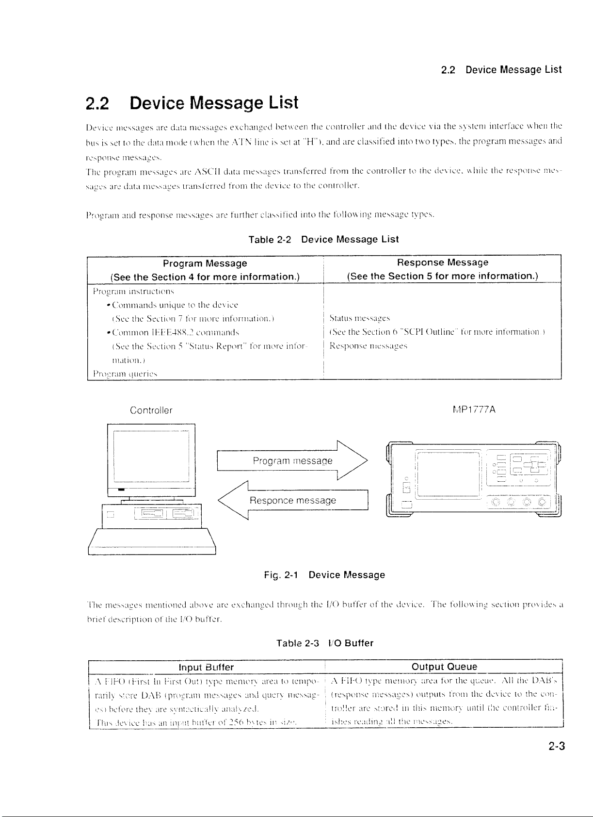
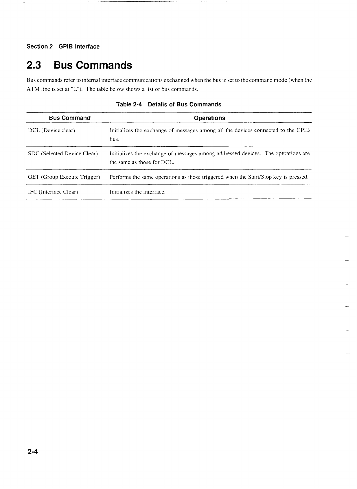
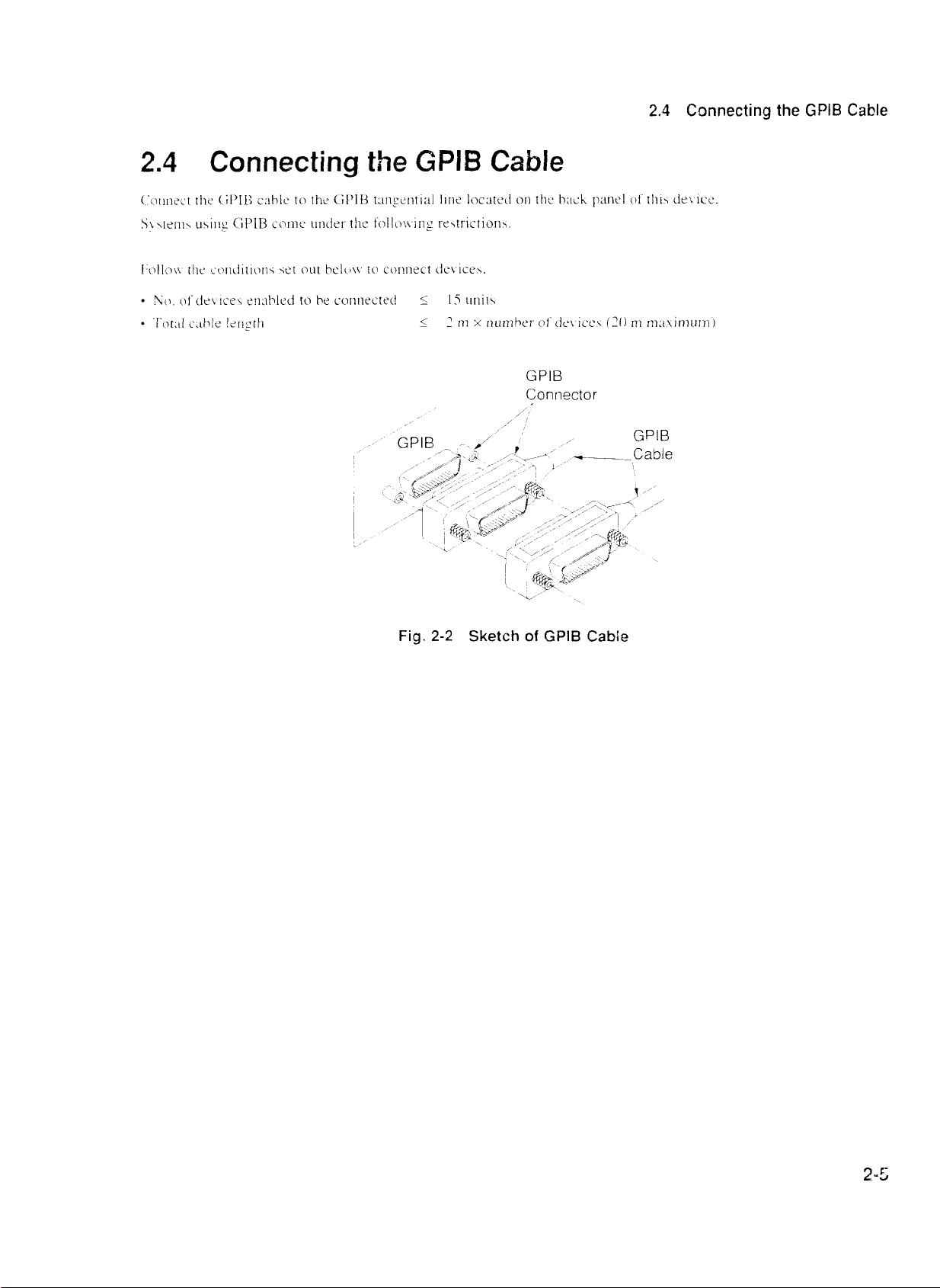
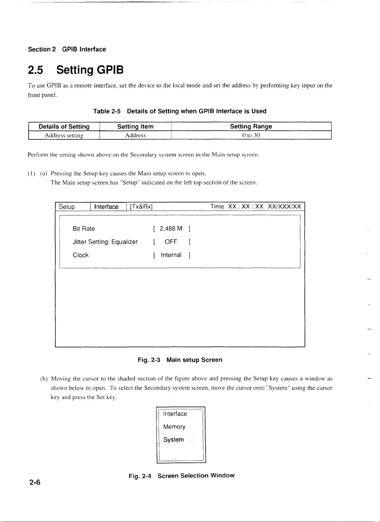
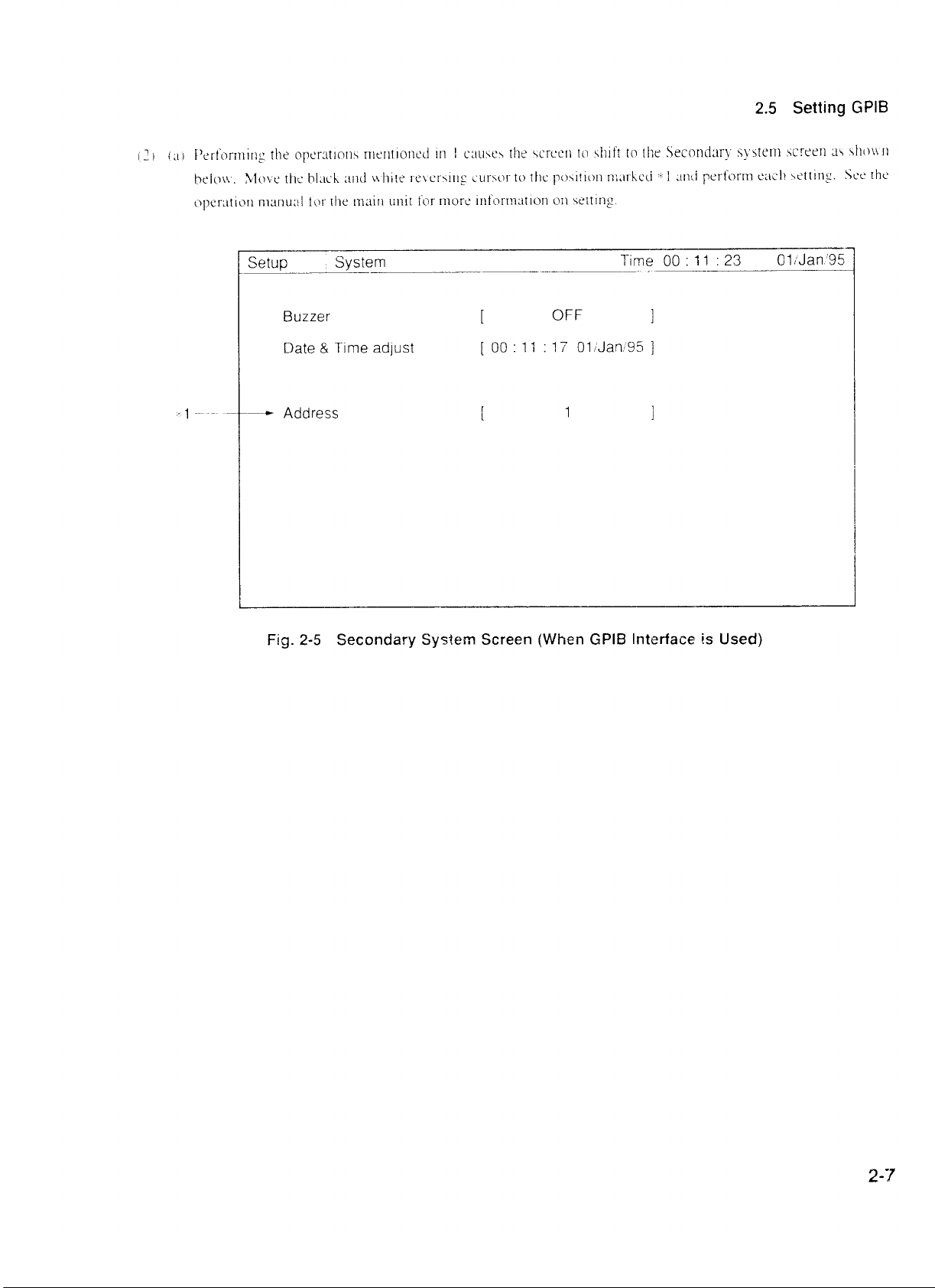
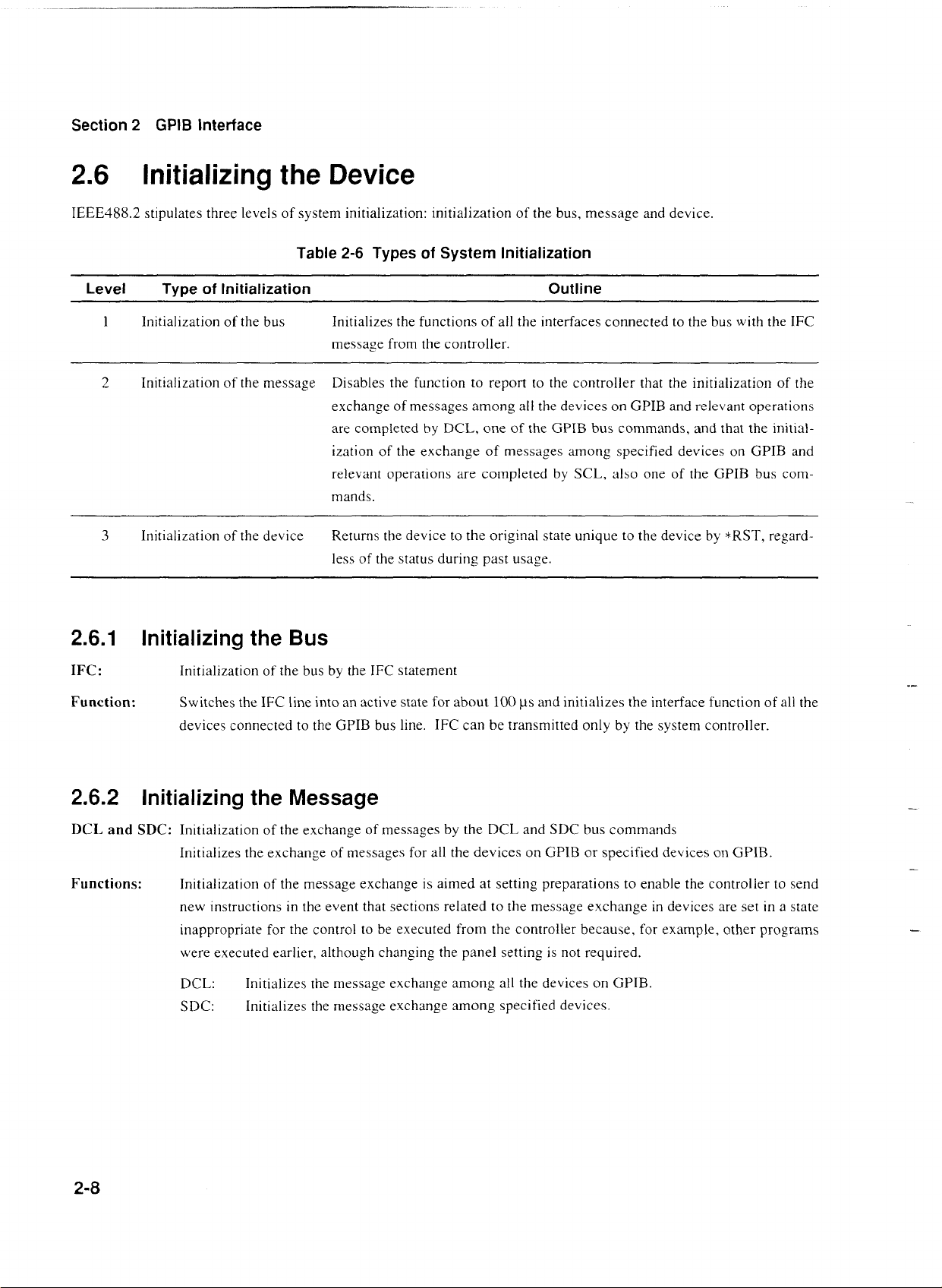
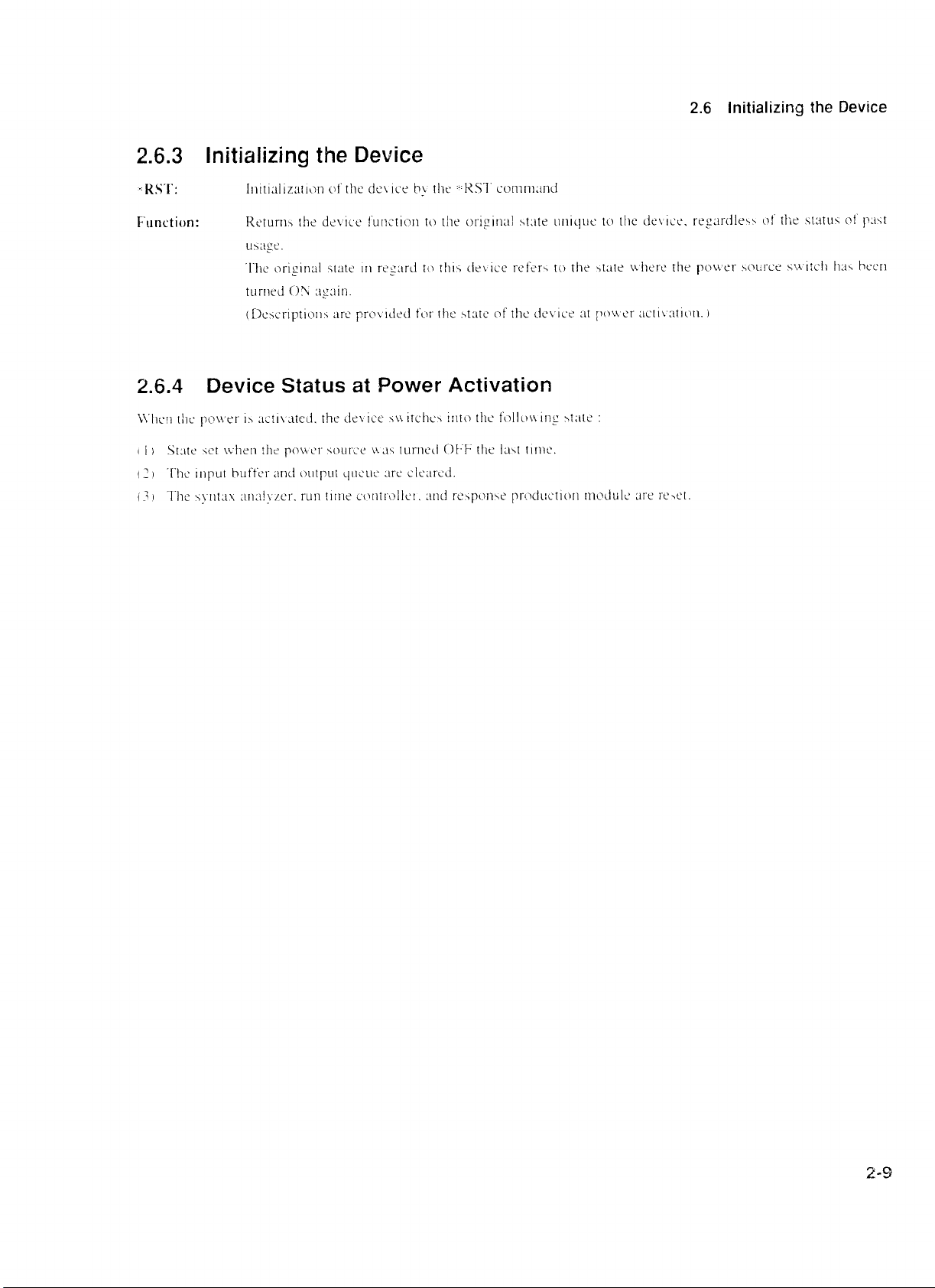

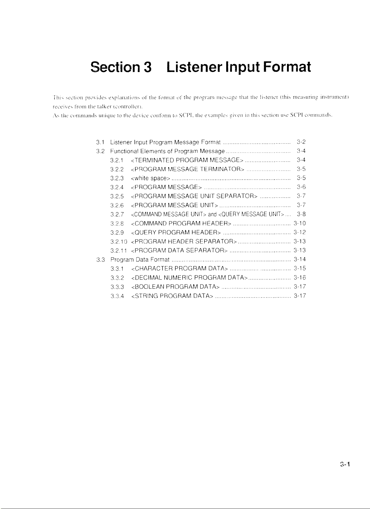
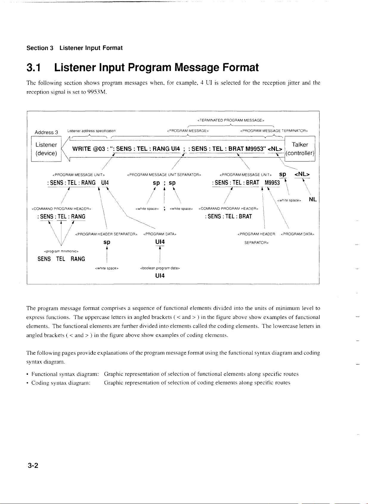
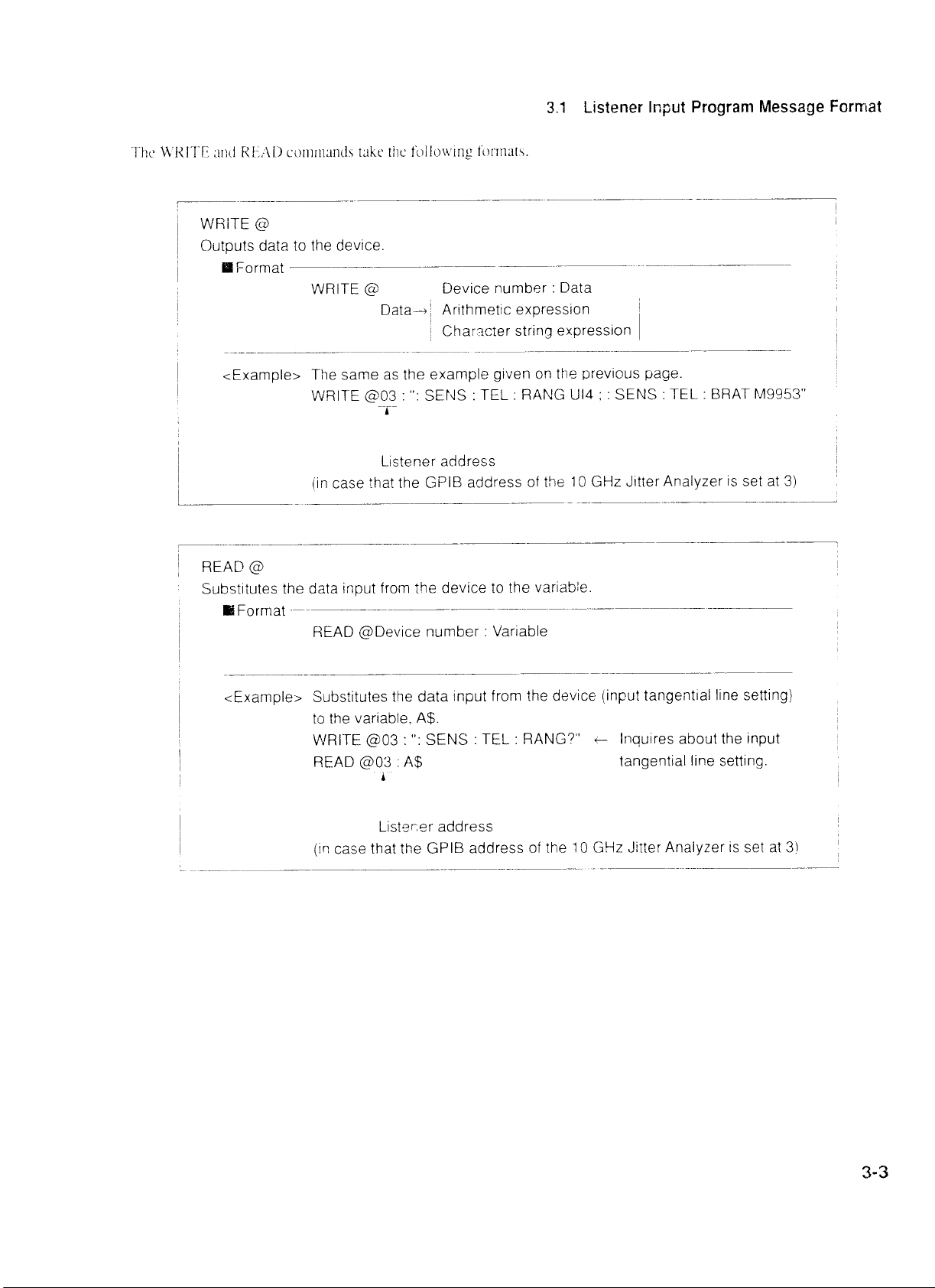


 Loading...