

Page 1

Artisan Technology Group is your source for quality
new and certified-used/pre-owned equipment
FAST SHIPPING AND
DELIVERY
TENS OF THOUSANDS OF
IN-STOCK ITEMS
EQUIPMENT DEMOS
HUNDREDS OF
MANUFACTURERS
SUPPORTED
LEASING/MONTHLY
RENTALS
ITAR CERTIFIED
SECURE ASSET SOLUTIONS
SERVICE CENTER REPAIRS
Experienced engineers and technicians on staff
at our full-service, in-house repair center
Ins traVew “ REMOTE INSPECTION
Remotely inspect equipment before purchasing with
our interactive website at
Contact us: (888) 88-SOURCE | sales@artisantg.com | www.artisantg.com
www.instraview.com
WE BUY USED EQUIPMENT
Sell your excess, underutilized, and idle used equipment
We also offer credit for buy-backs and trade-ins
www.artisantg.com/WeBuyEquipment ^
LOOKING FOR MORE INFORMATION?
Visit us on the web at www.artisantg.com ^ for more
information on price quotations, drivers, technical
specifications, manuals, and documentation
Page 2

MP1777A
10 GHz Jitter Analyzer
Remote Control
Operation Manual
Vol. 2
Fourth Edition
To ensure that the equipment is used safely, read
the "For Safety" in the MP1777A 10 GHz Jitter Ana
lyzer Operation Manual first.
Keep this manual with the equipment.
APR.
2005
ANRITSU CORPORATION
Document No.: M-W14S3AE-4.0
Artisan Technology Group - Quality Instrumentation ... Guaranteed | (888) 88-SOURCE | www.artisantg.com
Page 3

Safety Symbols
To prevent the risk of personal injury or loss related to equipment malfunction, Anritsu Corporation uses the follow
ing safety symbols to indicate safety-related information. Insure that you clearly understand the meanings of the
symbols BEFORE using the equipment.
Some or all of the symbols may not be used on this equipment. In addition, when drawings are included in this
manual, labels on the equipment may not be shown on them.
Safety Symbols Used in Manual
A KiOCD /\ indicates a very dangerous procedure that could result in death or serious
injury if not performed properly.
1»# * rj 1^11^^ This indicates a hazardous procedure that could result in death or serious injury if
VVMrilNIIMVj ¿_A not performed properly.
^*1 This indicates a hazardous procedure or danger that could result in light-to-severe
¿-lA injury, or loss related to equipment malfunction, if proper precautions are not taken.
Safety Symbols Used on Equipment and/or in Manual
The following safety symbols are used inside or on the equipment near operation locations, and./or in manual to
provide information about safety items and operation precautions. Insure that you clearly understand the mean
ings of the symbols and take the necessary precautions BEFORE using the equipment.
This indicates a prohibited operation. The prohibited operation is indicated sym
bolically in or near the barred circle.
This indicates an obligatory safety precaution. The obligatory operation is indi
cated symbolically in or near the circle.
This indicates warning or caution. The contents are indicated symbolically in or
near the triangle.
This indicates a note. The contents are described in the box.
These indicate that the marked part should be recycled.
MP1777A
10 GHz Jitter Analyzer Remote Control
Operation Manual Vol. 2
10 September 1998 (First Edition)
20 September 2002 (Fourth Edition)
Copyright © 1998-2002, ANRITSU CORPORATION.
All rights reserved. No part of this manual may be reproduced without the prior written permission of the
publisher.
The contents of this manual may be changed without prior notice.
Printed in Japan
II
Artisan Technology Group - Quality Instrumentation ... Guaranteed | (888) 88-SOURCE | www.artisantg.com
Page 4

A
For Safety
WARNING A
ALWAYS refer to the operation manual when working near locations at
which the alert mark shown on the left is attached. If the operation, etc.,
is performed without heeding the advice in the operation manual, there
is a risk of personal injury. In addition, the equipment performance may
be reduced.
Moreover, this alert mark is sometimes used with other marks and de
scriptions indicating other dangers.
2. When supplying power to this equipment, connect the accessory 3-pin
power cord to a 3-pin grounded power outlet, if a grounded 3-pin outlet
is not available, before supplying power to the equipment, use a conver
sion adapter and ground the green wire, or connect the frame ground on
the rear panel of the equipment to ground. If power is supplied without
grounding the equipment, there is a risk of receiving a severe or fatal
electric shock.
3. This equipment cannot be repaired by the user. DO NOT attempt to
Repair
warningA
Falling Over turned on its side, etc,, it will be unstable and may be damaged if it fal's
open the cabinet or to disassemble internal parts. Only Anritsu-trained
service personnel or staff from your sales representative with a knowl
edge of electrical fire and shock hazards should service this equipment.
There are high-voltage parts in this equipment presenting a risk of se
vere injury or fatal electric shock to untrained personnel. In addition,
there is a risk of damage to precision parts.
4. This equipm.ent should be used in the correct position. If the cabinet is
over as a result of receiving a slight mechanical shock.
Artisan Technology Group - Quality Instrumentation ... Guaranteed | (888) 88-SOURCE | www.artisantg.com
Page 5

Battery Fluid
LCD
For Safety
WARNING A
5. DO NOT short the battery terminals and never attempt to disassemble it
or dispose of it in a fire. If the battery is damaged by any of these ac
tions, the battery fluid may leak.
This fluid is poisonous.
DO NOT touch it, ingest it, or get in your eyes. If it is accidentally in
gested, spit it out immediately, rinse your mouth with water and seek
medical help. If it enters your eyes accidentally, do not rub your eyes,
irrigate them with clean running water and seek medical help. If the
liquid gets on your skin or clothes, wash it off carefully and thoroughly.
6. This instrument uses a Liquid Crystal Display (LCD); DO NOT subject
the instrument to excessive force or drop it. if the LCD is subjected to
strong mechanical shock, it may break and liquid may leak.
This liquid is very caustic and poisonous.
DO NOT touch it, ingest it, or get in your eyes. If it is ingested acciden
tally, spit it out immediately, rinse your mouth with water and seek medi
cal help. If it enters your eyes accidentally, do not rub your eyes, irrigate
them with clean running water and seek medical help. If the liquid gets
on your skin or clothes, wash it off carefully and thoroughly.
IV
Artisan Technology Group - Quality Instrumentation ... Guaranteed | (888) 88-SOURCE | www.artisantg.com
Page 6

Changing Fuse
A
Cleaning
ACAUTI0N/Æ,t
>18 kg
HEAVY WEIGHT.
For Safety
CAUTION A
1. Before changing the fuses, ALWAYS remove the power cord from the
poweroutlet and replace the blown fuses. ALWAYS use new fuses of
the type and rating specified on the fuse marking on the rear panel of the
cabinet.
T__A indicates a time-lag fuse.
There is risk of receiving a fatal electric shock if the fuses are replaced
with the power cord connected.
2. Keep the power supply and cooling fan free of dust.
- Clean the power inlet regularly. If dust accumulates around the power
pins, there is a risk of fire.
- Keep the cooling fan clean so that the ventilation holes are not ob
structed. If the ventilation is obstructed, the cabinet may overheat
and catch fire.
3. Use two or more people to lift and move this equipment, or use a trolley.
There is a risk of back injury, if this equipment is lifted by one person.
Changing memory
back-up battery
Disposing the batteries
4. This equipment uses a lithium battery to back-up the memory. This bat
tery must be replaced by a service engineer when it has reached the end
of its useful life: contact the Anritsu sales section or your nearest repre
sentative.
NOTE: The battery used in this equipment has a maximum useful life
of 7 years. It should be changed before this period has
elapsed.
5. The main unit of the MP1777A uses lithium batteries. When disposing of
the batteries, make sure to conform with the local regulation.
Artisan Technology Group - Quality Instrumentation ... Guaranteed | (888) 88-SOURCE | www.artisantg.com
Page 7

VI
Artisan Technology Group - Quality Instrumentation ... Guaranteed | (888) 88-SOURCE | www.artisantg.com
Page 8

Equipment Certificate
Anritsu Corporation certifies that this equipment was tested before shipment using
calibrated measuring mstruinents with direct traceability to public testing organiza
tions recognized bv national research laboratories including the Hlectrotechnical
Laboratory, the National Research Laboratory of Metrology and the Communications
Research Laboratory, and was found to meet the published specifications.
Anritsu Warranty
Anritsu Corporation will repair this equipment free-of-charge if a malfunction iiccurs
w ithin I y ear after shipment due to a manufacturing fault, provided that this w arranty
is rendered void under any or all of the following conditions.
• The lault is tMiiside the scope ol the warranty contiitions described m the operation
manual.
• d’he fault IS due to misiiantlling. misuse, or unauthorized modificaiion or repair of
the equipment by the customer.
• The fault is due to severe usage clearly e.vceeding normal usage.
• The fault is due to improper or insufficient intiintenance by the customer.
• The fault is due to natural disaster including fire, flooding, earthquake, etc.
• 'fhe fault is due to use of non-specified peripheral equipment, peripheral pans,
consumables, etc,
• The fault is due to use of a non '.pecified power supply or in a non-specified instal
lation location.
In addition, this w arranty is valid only for the original equipment purchaser, it is not
transferable if the equipment is resokl.
.Anritsu Ciirpomtioii will not accept liability for eijuipmem faults due to unforeseen
and unusual circumstances, nor for faults due to niishandiitis bv the customer.
Anritsu Corporation Contact
If this equipment develops a fault, contact .Anritsu Coiqioiation or its representatives
at the tiddress in this manual.
Vii
Artisan Technology Group - Quality Instrumentation ... Guaranteed | (888) 88-SOURCE | www.artisantg.com
Page 9

Notes On Export Management
This product and its manuals may require an Export License/Approval by
the Government of the product’s country of origin for re-export from your
country.
Before re-exporting the product or manuals, please contact us to confirm
whether they are export-controlled items or not.
When you dispose of export-controlled items, the products/manuals are
needed to be broken/shredded so as not to be unlawfully used for military
purpose.
Trademark and Registered Trademark
Quick Basic is a registered trademark of Microsoft Corporation.
vm
Artisan Technology Group - Quality Instrumentation ... Guaranteed | (888) 88-SOURCE | www.artisantg.com
Page 10

Composition of the MP1777A Operation Manual
The operation manual for the MP1777A lO GHz Jitter Analyzer ii, composed of the two \olunies shown below .
\oltime that suits the intended applicatiein of the product.
VOL. 1
Operation manual for the main unit
the
MP1777A
Operation Manual
Operation manual for the main unit:
Operation manual for remote control: This manual describes remote control and prcn ides proeram example-
VOL. 2
I'his manual prosades an outline of the MPI777A and its speeilieatmns,
iiid describes its panel, pertormance and operation.
Operation manual for remote control
Artisan Technology Group - Quality Instrumentation ... Guaranteed | (888) 88-SOURCE | www.artisantg.com
Page 11

Table of Contents
For Safety............................................................ Hi
Composition of the MP1777A Operation Manual.. I
Section 1 Outline
1.1 Interface Function
1.2 System Setup Example........................................................................1-3
Section 2 GPIB Interface
2.1 GPIB Interface Functions.....................................................................2-2
2.2 Device Message List............................................................................2-3
2.3 Bus Commands....................................................................................2-4
2.4 Connecting the GPIB Cable.................................................................2-5
2.5 Setting GPIB.........................................................................................2-6
2.6 Initializing the Device
Sections Listener Input Format
3.1 Listener Input Program Message Format
3.2 Functional Elements of Program Message..........................................3-4
3.3 Program Data Format
.............................................
................................................................................
.................................
...........................................................................
.........................
............................................
........................................................................
1-1
1-2
2-1
2-8
3-1
3-2
3-14
Section 4 Talker Output Format
4.1 Talker Output Response Message Format
4.2 Functional Elements of Response Message
Section 5 Common IEEE488.2 Commands
5.1 Common IEEE488.2........................................................................... 5-2
Artisan Technology Group - Quality Instrumentation ... Guaranteed | (888) 88-SOURCE | www.artisantg.com
........................
..........................................
.......................................
.....
4-1
4-2
4-3
5-1
Page 12

Section 6 Status Report
6.1 Configuration of MP1777A Status Registers.................................6-2
6.2 Status Registers Specified by IEEE488.2
6.3 Status Register Specified by SCPI................................................6-6
6.4 Status Register Specific to MP1777A
6.5 Reading, Writing and Clearing Status Registers........................... 6-8
..........................................
...................................
...........................................
6-1
6-4
6-7
Section 7 SCPI Outline
7.1 Outline ..........................................................................................7-2
7.2 Command Structure
7.3 Command Description Method......................................................7-4
7.4 Compounding Commands.............................................................7-5
7.5 Parameter......................................................................................7-6
Section 8 Device Message Details
8.1 Response Format..........................................................................8-2
8.2 Buffer Size Stipulations
8.3 Device-Specific Commands..........................................................8-5
Appendix A SCPI Error Messages
A.1 Command Errors.........................................................................A-2
A.2 Run Time Errors
A.3 Device-Specific Errors..................................................................A-5
A. 4 Query Errors.................................................................................A-6
...........................................
....................................................................
.........................
.................................................................
.....................
..........................................................................
. A-1
7-1
7-3
8-1
8-4
A-4
Appendix B Details of Initialization Command
Functions
B. 1 Initiaiizing Bus..............................................................................B-2
B.2 Initializing Message......................................................................E-3
B.3 Initializing Device
B.4 Device Status at Power Activation ..................................................B-5
Artisan Technology Group - Quality Instrumentation ... Guaranteed | (888) 88-SOURCE | www.artisantg.com
.........................................................................
.......................................
B-1
B-4
\\\
Page 13

IV.
Artisan Technology Group - Quality Instrumentation ... Guaranteed | (888) 88-SOURCE | www.artisantg.com
Page 14

Section 1 Outline
'I’hc MP1777A 10 CiH/ Jitter Analyzer enables automation of measurement when connected with an external controller.
The GPIB interlace is used for connection. I'his section pros'iiles explanations ol' interface functions and sS steni setup
extimples.
1.1 Interface Function................................................................................. 1-2
1.2 System Setup Example........................................................................ 1-3
Artisan Technology Group - Quality Instrumentation ... Guaranteed | (888) 88-SOURCE | www.artisantg.com
1-1
Page 15

Section 1 Outline
1.1 Interface Function
The MP1777A has a connector for remote control on the back face.
Remote control of devices is enabled by fitting GPIB.
The GPIB setting is performed on the Secondary system screen in the Main setup screen.
GPIB interface: The GPIB interface for this device conforms to the IEEE (Institute of Electrical and Electronic Engi
neers) standards, 488.1-1987. The software conforms to the standards IEEE488.2 and SCPI (Standard
Commands for Programmable Instruments). (See the Section 7 for more infomiation.)
This device incorporates the following interface functions.
■ Control of functions except for certain functions such as power source switch and Local key.
• Reading of all the setup conditions and screen display.
1-2
Artisan Technology Group - Quality Instrumentation ... Guaranteed | (888) 88-SOURCE | www.artisantg.com
Page 16

1.2 System Setup Example
The figure below slrows an example ol'aystem setup using: an interface.
Control from a host computer
When connected to a host computer, the de\ ice performs automatic measurement.
1.2 System Setup Example
MP1777A
Host computer
Fig. 1-1 Block Diagram
Artisan Technology Group - Quality Instrumentation ... Guaranteed | (888) 88-SOURCE | www.artisantg.com
1-:
Page 17

Section 1 Outline
1-4.
Artisan Technology Group - Quality Instrumentation ... Guaranteed | (888) 88-SOURCE | www.artisantg.com
Page 18

Section 2 GPIB interface
[his section provides descriptions ot the CjPIB interlace iunctions and scttitic method in the event that the interiacc
used as an option.
2.1 GPIB Interface Functions
2.2 Device Message List
2.3 Bus Commands................................................................................... 2-4
2.4 Connecting the GPIB Cable
2.5 Setting GPIB ....................................................................................... 2-6
2.6 Initializing the Device........................................................................... 2-8
2.6.1 Initializing the Bus................................................................... 2-8
2.6.2 Initializing the Message
2.6.3 Initializing the Device.............................................................. 2-9
2.6.4 Device Status at Power Activation
....................................................................
...........................................................................
................................................................
..........................................................
..........................................
2-2
2-3
2-5
2-8
2-9
Artisan Technology Group - Quality Instrumentation ... Guaranteed | (888) 88-SOURCE | www.artisantg.com
2-1
Page 19

Section 2 GPIB Interface
2.1 GPIB Interface Functions
This device only functions as a device and does not function as a controller. Accordingly, the GPIB interface has the
following functions.
Table 2-1 GPIB Interface Functions
Cord Interface Function
SHI All the source handshake functions is available.
AHl All the acceptor handshake functions is available.
Basic talker functions is available.
T5
L4
SRI
RLl
PPO No parallel port function is available.
DCl
DTI
CO No system controller functions is available.
Serial port function is available.
Talk only mode function is available.
Talker cancellation function is by MLA available.
Basic listener functions is available.
No listen only mode function is available.
Listener cancellation function is by MTA available.
All the service request functions is available.
All the remote and local functions is available.
All the device clear functions is available.
All the device trigger functions is available.
IEEE488.2 Standards
Incorporation of all the functions as the standard features
Incorporation of all the functions as the standard features
The device shall incorporate one of the following sub
sets: T5, T6, TE5 or TE6.
The device shall incorporate one of the following sub
sets: L3, L4, LE3 or LE4.
Incorporation of all the functions as the standard features
RLO (no functions) or RLl (all functions)
PPO (no functions) or PPl (all functions)
Incorporation of all the functions as the standard features
DTO (no functions) or DTI (all functions)
CO (no functions), C4 and C5, or one of the following
sub-sets: C7, C9 or C11.
2-2
Artisan Technology Group - Quality Instrumentation ... Guaranteed | (888) 88-SOURCE | www.artisantg.com
Page 20

2.2 Device Message List
2.2 Device Message List
Device iiicssaizes are data nicssaees exchanged betv'.cen thie controller and the device via the system interface when tlie
bus is set to the data mode (when the ATN line is set at "H"). and are classified into two types, the program messages and
response messages.
fhe prrieram messages are ASC.’II data messages transferred from the controller to the de^vice. while the response nies-
saees are tlata messaees transferred from the device to the controller.
Froeram and response messages are ftirlher classified into tfie following message types.
Table 2-2 Device Message List
Program Message
(See the Section 4 for more information.)
Program instructions
•Commands unique to the des iee
(See the Section 7 for more information.)
•Common IHFE4SS.2 commands
(See the Section .7 "Status Report" for more infor
mation. )
f-’rogram (lueries
Controller
Response Message
(See the Section 5 for more information.)
Status messages
(See the Section b "SCPI Outline" for more infomiation )
Response messages
MP1777A
Fig. 2-1 Device Message
d'he messages mentioned above are exchanged throngfi the I/O buffer of the device. 'Fhe following section pros ides a
brief description of tiie f/() buffer.
Table 2-3 I/O Buffer
Input Buffer
.Л t IR) i hirst In l-drst Out) type memorx area to tempo- ' A f-ihO type memor> area for the queue. .ЛИ iiie D.-\B's
rarily s'ore D.AB (progr.im messages and срасгу messag- I (response messages) outputs from the device to the con
es i before ihev are svntacticaily anal\/ed. ' troller arc stored in tiiis memory until the controller fin-
filis de\ ice has an tni ii! hut'ler of d.^b bvtes In si/ss ■ isb.es reading ah the liiessages.
Output Queue
2-3
Artisan Technology Group - Quality Instrumentation ... Guaranteed | (888) 88-SOURCE | www.artisantg.com
Page 21

Section 2 GPIB Interface
2.3 Bus Commands
Bus commands refer to internal interface communications exchanged when the bus is set to the command mode (when the
ATM line is set at "L"). The table below shows a list of bus commands.
Table 2-4 Details of Bus Commands
Bus Command
DCL (Device clear) Initializes the exchange of messages among all the devices connected to the GPIB
bus.
SDC (Selected Device Clear) Initializes the exchange of messages among addressed devices. The operations are
the same as those for DCL.
GET (Group Execute Trigger) Performs the same operations as those triggered when the Start/Stop key is pressed.
IFC (Interface Clear) Initializes the interface.
Operations
2-4
Artisan Technology Group - Quality Instrumentation ... Guaranteed | (888) 88-SOURCE | www.artisantg.com
Page 22

2.4 Connecting the GPIB Cable
2.4 Connecting the GPIB Cable
(Àninect the tiPIli cable to the Gl’lB tangential line located on the btick panel of this dev ice.
S\stents usnu; GPIEi come under the following restrictions.
l-ollow the conditions set out below to connect devices.
• No. of dev ices enabled to be connected < 15 units
• Total cable leiiL'th < 2 m x number of devices (20 m ma.ximtim )
GPIB
Connector
GPIB
- T-'-
t's
Fig, 2-2 Sketch of GPIB Cable
GPIB
Cable
Artisan Technology Group - Quality Instrumentation ... Guaranteed | (888) 88-SOURCE | www.artisantg.com
2~5
Page 23

Section 2 GPIB Interface
2.5 Setting GPIB
To use GPIB as a remote interface, set the device to the local mode and set the address by performing key input on the
front panel.
Table 2-5 Details of Setting when GPIB Interface is Used
Details of Setting
Address setting
Perform the setting shown above on the Secondary system screen in the Main setup screen.
(1) (a) Pressing the Setup key causes the Main setup screen to open.
The Main setup screen has "Setup" indicated on the left top section of the screen.
Setup
Bit Rate
Jitter Setting; Equalizer
Clock
Interface [Tx&Rx]
Setting Item
Address Oto 30
Time XX ; XX : XX XX/XXX/XX
[ 2,488 M ]
[ OFF ]
[ Internal ]
Setting Range
Fig. 2-3 Main setup Screen
(b) Moving the cursor to the shaded section of the figure above and pressing the Setup key causes a window as
shown below to open. To select the Secondary system screen, move the cursor onto "System" using the cursor
key and press the Set key.
Fig. 2-4 Screen Selection Window
2-6
Artisan Technology Group - Quality Instrumentation ... Guaranteed | (888) 88-SOURCE | www.artisantg.com
Page 24

2.5 Setting GPIB
(a) [’erforniing tlie operations mentioned in I causes the screen to shift to the Secondary system screen as shown
below. Move the black and white reversing cursor to the position marked * 1 and perform each setting. See the
operation manual lor the main unit for more information on setting.
Setup
Buzzer
Date & Time adjust
System
[ OFF
[ 00 : 11 : 17 01/Jan,''95
Time 00:11 : 23
Address
Fig. 2-5 Secondary System Screen (When GPIB Interface is Used)
01/Jan,'95
Artisan Technology Group - Quality Instrumentation ... Guaranteed | (888) 88-SOURCE | www.artisantg.com
2-7
Page 25

Section 2 GPIB Interface
2.6 initializing the Device
IEEE488.2 stipulates three levels of system initialization: initialization of the bus, message and device.
Table 2-6 Types of System Initialization
Level
1 Initialization of the bus Initializes the functions of all the interfaces connected to the bus with the IFC
2 Initialization of the message Disables the function to report to the controller that the initialization of the
3 Initialization of the device Returns the device to the original state unique to the device by *RST, regard
Type of Initialization Outline
message from the controller.
exchange of messages among all the devices on GPIB and relevant operations
are completed by DCL, one of the GPIB bus commands, and that the initial
ization of the exchange of messages among specified devices on GPIB and
relevant operations are completed by SCL, also one of the GPIB bus com
mands.
less of the status during past usage.
2.6.1 Initializing the Bus
IFC: Initialization of the bus by the IFC statement
Function: Switches the IFC line into an active state for about 100 |is and initializes the interface function of all the
devices connected to the GPIB bus line. IFC can be transmitted only by the system controller.
2.6.2 Initializing the Message
DCL and SDC: Initialization of the exchange of messages by the DCL and SDC bus commands
Initializes the exchange of messages for all the devices on GPIB or specified devices on GPIB.
Functions: Initialization of the message exchange is aimed at setting preparations to enable the controller to send
new instructions in the event that sections related to the message exchange in devices are set in a state
inappropriate for the control to be executed from the controller because, for example, other programs
were executed earlier, although changing the panel setting is not required.
DCL: Initializes the message exchange among all the devices on GPIB.
SDC: Initializes the message exchange among specified devices.
2-8
Artisan Technology Group - Quality Instrumentation ... Guaranteed | (888) 88-SOURCE | www.artisantg.com
Page 26

2.6 Initializing the Device
2.6.3 Initializing the Device
<RST; Initializaiion of the dcMce by the ^-^RST eommand
Function: Returns the device function to the original sttite unique to the device, regardless of tlie status ol past
usage.
Tfie original state in regard to tins device refers to the state where the power sotu'ce switch has been
turned ON agtiin.
( Descriptions are provided for the state of the device at fiower actis aiion.)
2.6.4 Device Status at Power Activation
When tlie pocver is ;icti\ated. the device sv\ itches into the following stale :
( I ) .State set when the power source was turncil Of-’F die last time.
(di The input buffer and output queue are cleared.
(3i The s\nta\ anaiw.er. run time controllei. and response production module are rcwet.
Artisan Technology Group - Quality Instrumentation ... Guaranteed | (888) 88-SOURCE | www.artisantg.com
2-9
Page 27

Section 2 GPIB Interface
2-10.
Artisan Technology Group - Quality Instrumentation ... Guaranteed | (888) 88-SOURCE | www.artisantg.com
Page 28

Section 3 Listener Input Format
riiis section provides explanations t)l the tormat rif tiie program message th;it the listener (this niettsuritig instrument)
receives from the talker (cciturollen.
As tile commands unique to the device conform to SCPl, llie extimples given m this section use SCPI coinmaiids.
3.1 Listener Input Program Message Format
3.2 Functional Elements of Program Message
3.2.1 <TERMINATED PROGRAM MESSAGE>
3.2.2 <PROGRAM MESSAGE TERMINATOR> ............................. 3-5
3.2.3 <white space>......................................................................... 3-5
3.2.4 <PROGRAM MESSAGE> ...................................................... 3-6
3.2.5 <PROGRAM MESSAGE UNIT SEPARATOR> ..................... 3-7
3.2.6 <PROGRAM MESSAGE UNIT>
3.2.7 <COMMAND MESSAGE UNIT> and <QUERY MESSAGE UNIT>.... 3-8
3.2.8 <COMMAND PROGRAM HEADER>
3.2.9 <QUERY PROGRAM HEADER>
3.2.10 <PROGRAM HEADER SEPARATOR>
3.2.11 <PROGRAM DATA SEPARATOR>
3.3 Program Data Format......................................................................... 3-14
3.3.1 <CHARACTER PROGRAM DATA>
3.3.2 <DECIMAL NUMERIC PROGRAM DATA>.......................... 3-16
3.3.3 <BOOLEAN PROGRAM DATA>
3.3.4 <STR1NG PROGRAM DATA>
.............................................
...........................................
..............................
.............................................
...................................
........................................
................................
....................................
.....................................
...........................................
.............................................
3-2
3-4
3-4
3-7
3-10
3-12
3-13
3-13
3-15
3-1 7
3-17
Artisan Technology Group - Quality Instrumentation ... Guaranteed | (888) 88-SOURCE | www.artisantg.com
Page 29
Section 3 Listener Input Format
3.1 Listener Input Program Message Format
The following section shows program messages when, for example, 4 UI is selected for the reception jitter and the
reception signal is set to 9953M.
<TERMINATED PROGRAM MESSAGE>
Address 3
Listener address specification
A' '' ' V ^
Listener
(device)
/
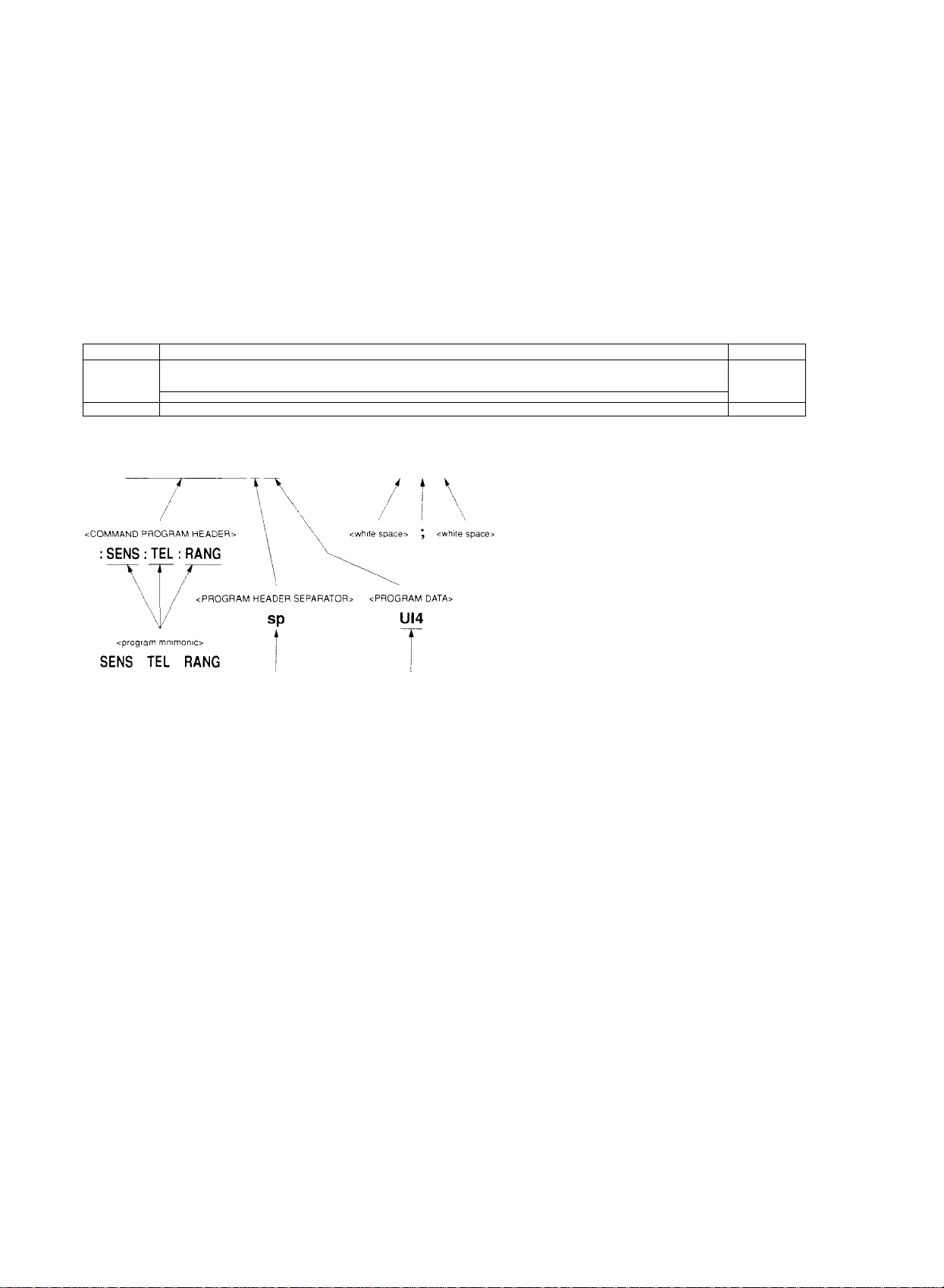
( WRITE (0)03 : SENS : TEL ; RANG UI4 ; ; SENS ; TEL ; BRAT M9953" <NL>
\ / / V V
N /' / '\ '\
<PROGRAM MESSAGE UNIT>
: SENS : TEL : RANG UI4
<white space>
<PROGRAM MESSAGE>
<PROGRAM MESSAGE UNIT SEPARATOR»
sp ; sp
<boolean program data>
UI4
<PROGRAM MESSAGE TERMINATOR>
Talker
(controller)
<PROGRAM MESSAGE UNIT» SP <NL>
; SENS : TEL : BRAT M9953^, \
\
\ <white space> NL
: SENS : TEL : BRAT
<PROGRAM HEADER <PROGRAM DATA>
SEPARATOR>
The program message format comprises a sequence of functional elements divided into the units of minimum level to
express functions. The uppercase letters in angled brackets ( < and > ) in the figure above show examples of functional
elements. The functional elements are further divided into elements called the coding elements. The lowercase letters in
angled brackets ( < and > ) in the figure above show examples of coding elements.
The following pages provide explanations of the program message format using the functional syntax diagram and coding
syntax diagram.
• Functional syntax diagram: Graphic representation of selection of functional elements along specific routes
• Coding syntax diagram: Graphic representation of selection of coding elements along specific routes
3-2
Artisan Technology Group - Quality Instrumentation ... Guaranteed | (888) 88-SOURCE | www.artisantg.com
Page 30

The WKIlTe and RTAD coniniands take tlic foilo\vin>t fonnals.
WRITE @
Outputs data to the device.
■a rumiaL
WRITE @
Data-
Device number : Data
Arithmetic expression
Character string expression
3.1 Listener Input Program Message Format
i
<Example>
The same as the example given on the previous page.
WRITE @03 : SENS ; TEL : RANG UI4 ; : SENS : TEL ; BRAT M9953"
i
Listener address
(in case that the GPIB address of the 10 GHz Jitter Analyzer is set at 3)
READ @
Substitutes the data input from the device to the variable.
K Format-------------------------------------------------------------
READ @Device number : Variable
<Example> Substitutes the data input from the device (input tangential line setting)
to the variable, A$.
WRITE @03 SENS : TEL : RANG')'" <- Inquires about the input
READ @03 : A$ tangential line setting,
i
Listener address
(in case that the GPIB address of the 10 GHz Jitter Analyzer is set at 3)
Artisan Technology Group - Quality Instrumentation ... Guaranteed | (888) 88-SOURCE | www.artisantg.com
3-3
Page 31

Section 3 Listener Input Format
3.2 Functional Elements of Program Message
This measuring instrument accepts the program message by detecting the terminator located at the end of the program
message. The following section explains each functional element of the program message.
3.2.1 <TERMINATED PROGRAM MESSAGE>
The <TERMINATED PROGRAM MESSAGE> is defined as follows.
<PROGRAM
<PROGRAM MESSAGE>
.
Refer to 3.2.4
The <TERMINATED PROGRAM MESSAGE> constitutes a data message that incorporates all the functional elements
necessary for the controller to send data to this measuring instrument.
To complete the transfer of the <PROGRAM MESSAGE>, the <PROGRAM MESSAGE TERMINATOR> is added to
the end of the <PROGRAM MESSAGE>.
MESSAGE
TERMINATOR>
Refer to 3.2.2
Example: <TERMINATED PROGRAM MESSAGE> to send two instructions
3-4
Artisan Technology Group - Quality Instrumentation ... Guaranteed | (888) 88-SOURCE | www.artisantg.com
Page 32

3.2 Functional Elements of Program Message
3.2.2 <PROGRAM MESSAGE TERMINATOR>
The <PR()CiRAM MESSAGE TERMlNArOR> in the case of using the GPIH interface is defined as follows.
<white space>
NL
--------------------- aEND
Refer to 3.2.3 J
NL i
le <PROGRAM MHSS.AGE TF.RMIN.‘\TOR> ends a sequence of one or multiple <FR()(iRAM .MH.SS.AGli I'NTT;
cments ot certain leneth.
NL;
F.ND:
Defined a.s a single .A-SGII code h\te 0.-\ ( 10 of deeinial digit). Nameh. this constitutes an .ASC'll
control character EE' (Line Feed) and performs the new line operalions to return the printing position to
the same character position on the next line. .As this eauses printing to start from a new line, it is also
called the Ni. (New Line).
Generates the EfOl signal b\- setting the E(.)l (Fhid-or-ldentifv) line, which is one of the GPU.-! control
buses, to TRUE, (the LOW level).
'Erie Statements to control the HOI line includes the EOl ON/OFE statement.
3.2.3 <white space>
'I’he <w Elite space> is defined as follow s
<white space
character>
Ehe <white space character> is defined as the single .ASCII code b\ te in the ranges of .ASCII code bytes of between (K)
and 09 and between 013 to 20 ideeiinal digits, 0 to 9 and I I to 32i.
1 he .ASCII control svmbol and blank s_\ nibol w ith an exception of the New Lane arc included in the range. Howev er, this
measuring instrument does not inteqrrct them as ASCII control symbols but sinipK' processes them as space or skips
readiiie them.
Artisan Technology Group - Quality Instrumentation ... Guaranteed | (888) 88-SOURCE | www.artisantg.com
3-5
Page 33

Section 3 Listener Input Format
3.2.4 <PROGRAM MESSAGE>
The <PROGRAM MESSAGE> is defined as follows.
The <PROGRAM MESSAGE> is composed of a sequence of zero, one or multiple <PROGRAM MESSAGE UNIT>
elements.
The <PROGRAM MESSAGE UNIT> elements signify programming instructions or data to be sent from the controller to
this measuring instrument. The <PROGRAM MESSAGE UNIT SEPARATOR> is used as the separator for delimitting
multiple <PROGRAM VIESSAGE UNIT> elements.
Example: Selects the reception jitter range of 4 UI and sets the reception signal to 9953M.
<PROGRAM MESSAGE>
^^
: SENS : TEL : RANG U14 ; : SENS : TEL : BRAT M9953
T
cPROGRAM MESSAGE UNIT SEPARATOR>
<PROGRAM MESSAGE UNIT>
<PROGRAM MESSAGE UNIT>
3-6
Artisan Technology Group - Quality Instrumentation ... Guaranteed | (888) 88-SOURCE | www.artisantg.com
Page 34

3.2 Functional Elements of Program Message
3.2.5 <PROGRAM MESSAGE UNIT SEPARATOR>
1 he <PR()GRAM MESSAGE L'MT SEPARA'r()R> is defined as follovss.
<white space>
Refer to 3.2.3
The <\\hiie spaco is defined as follovs s.
<white space
character>
I he <PROGR.'\M MESSAGE GMT SEP.AR.\d’OR> di\ ides a .sequence of nuiliiple <PROGk,\M MESS.AGE ENl
eleinenis w ithin ttie range of the <I^ROCrR.-\M M1',SS.‘\GE>.
fhis measuring instrument interprets a semicolon ( ; ) as the separator tor the <PROGR,\M ME.SSAfiE IcNI I >.
Therefore, the <white space character> located before and after the semicolon I ; ) is skip.ped.
Nonetheless, the <white space character> is effective in facilitating the reading of ilie program.
3.2.6 <PROGRAM MESSAGE UNIT>
I he <PROGR.'\M MESSAGE UNIT> is defined as follows.
<COMMAND MESSAGE>
Refer to 3.2.7
kQUERY MESSAGE UNITe
Refer to 3.2.7
The <PROGRAM .MESSAGE UN1T> comprises the <COM.MAND MESSAGE l’MT>, which constitutes a single com
mand message received bv this measuring itistrument. or <QEER't' MESS.AGE UNIT>, whicli constitutes ;i single query
mess.ice.
Artisan Technology Group - Quality Instrumentation ... Guaranteed | (888) 88-SOURCE | www.artisantg.com
3-7
Page 35

Section 3 Listener Input Format
3.2.7 <COMMAND MESSAGE UNIT> and <QUERY MESSAGE UNIT>
(1) The <COMMAND MESSAGE UNIT> is defined as follows.
Example: Sets the data.
3-8
Artisan Technology Group - Quality Instrumentation ... Guaranteed | (888) 88-SOURCE | www.artisantg.com
Page 36

I'he <QUHRY MHSSACiEi UMT> is defined as follows.
3.2 Functional Elements of Program Message
<PROGRAM \
DATA
SEPARATOR>
Refer to 3.2.11 / "
<QUERY
PROGRAM
HEADER>
Refer to 3.2.9
Example: Inquires about the analyzed data of the error or alarm.
<PROGRAM
HEADER
SEPARATOR>
.^Refer to 3.2.10,
<PROGRAM DATA>
.. PROGRAM 3A~A >
: CALC : TGR : DATA? 1995,3,27,12,54
^ " '' i V V k i
"PCGBAV HEADER SEPARATOR;.
5PY PROGRAM HEAT
Wiien the proertmi data follows tlie program header of <CO.\1M.‘\ND MESS.ACiE L'N'llG and <QUER'i’ ME.S.S.A(iE
t^NlTo. a space character is alvs a\s entered between them as a separator. The progrtini application, function ;ind opera
tion c;in be identified b\' the program header. In the absence ot’ the program data t(> lollow the program header, the
program header alone expresses the application, funenon and operation to be executed ni this measuring instrument.
■; = ROGRAV DATA ;EPARATOR>
flic <COMM.-\ND PROGR.AM HE.ADER> in the program lieader functions as a command to be used b\ the controller to
control this measuring instrument, while the <QUFRY PROGRM llE,ADEFf> is a query command that the controller
preliminanlv sends lo this measuring instrument so that the cinnroller will be able to receive the response message Irom
this measuring instrument. It is alw a\ s characterized b\ the addition of the quer\ indicator, or a question mark i 1 ), to the
end of the header.
3-9
Artisan Technology Group - Quality Instrumentation ... Guaranteed | (888) 88-SOURCE | www.artisantg.com
Page 37

Section 3 Listener Input Format
3.2.8 <COMMAND PROGRAM HEADER>
The <COMMAND PROGRAM HEADER> is defined as follows.
The <while space> can be placed before each header.
(1) The <Instrument-Control Headers> are defined as follows.
(2) The <common command program header> is defined as follows.
_________________________>
f3) The <program mnemonio is defined as follows.
3-10
<program mnemonio
Refer to (3) of 3.2.8
Artisan Technology Group - Quality Instrumentation ... Guaranteed | (888) 88-SOURCE | www.artisantg.com
Page 38

3.2 Functional Elements of Program Message
3.2.8.1 <COMMAND PROGRAM HEADER>
The <COMMAND PROGRAM HEADI’R> expresses the appiication, f unction and operation of tlie program data to he
executed hv this measuring instrument. In the absence of the program data to follow the command program header, the
command program lieader alone expresses the application, function and operation to be executed in this measuring instru
ment.
The <program mnemonio expresses th.ese meanings b\ .ASCII code ciiaracters, and is generally called the mnemonic.
3.2.8.2 <program mnemonio
The header of the mnemonic ah\ ays begins \v iih an uppercase or lowercase character. Then, it is followed b_\ an arbiirarx
combm.ilion of uppercase characters (.A to Z), lowercase characters (a to z), an underline ( _ ). and digits from 0 to d, lie
mnemonic come-, in a ma.ximum length of I 2 characters, with no space inserted between characters.
(1) <upper,lower case alpha>
.'''pecified as a single .ASCII code byte m the range of .ASCII code b\ tes between 4 1 and .d.A, and 6 I and 7.\ ib.o to 4()
and 97 to 122 of decimal digits = uppercase characters (,A to Zi and lowercase characters (a to zi).
(2) <digit>
S|iecified as a single .ASCII code byte in the range of .ASCII code b\tes between 30 and 39 (4S to .37 of decimal digits
= numerical values between 0 and 9).
(3) (_)
Specifieii as ;i single .ASCII code b\te in ilie range of .ASCII code b_\te of 31- (93 ofdecimal digit = underlmei.
3.2.8.3 <!nstrument-Controi Headers>
Flic <lnstrument-Ccintrol Headers> are specified by SCPI. .As the de\ ice-specific commands of this measuring instru
ment conform to SCPI, the command format used is that of this programming language.
(1) <short form mnemonio and <long form mnemonic>
Corresponds to the short form and long form of the SCPI commands. The stipulations of <program mnemonio
mentioned above appK' as the\ tire its the mnemonic stipulations.
(2) <numeric suffix>
Specified as a single .ASCII code b\tc in the range of .ASCII code bytes between 30 and 39 (4S to 37 ofdecimal digit
= numerical wilues between 0 and 9).
3.2.8.4 <common command program header>
The <common command |srogram header> aK\a> s has an asterisk ( i betöre the <prograr,. mnemonio.
Artisan Technology Group - Quality Instrumentation ... Guaranteed | (888) 88-SOURCE | www.artisantg.com
3-11
Page 39

Section 3 Listener Input Format
3.2.9 <QUERY PROGRAM HEADER>
The <QUERY PROGRAM HEADER> is defined as follows.
The <white space> can be placed before each header.
(1) The <Instrument-Control Headers> are defined as follows.
(2) The <common query program header> is defined as follows.
__________
<program mnemonio
^
Refer to (3) of 3.2.8
3.2.9.1 <QUERY PROGRAM HEADER>
The <QUERY PROGRAM HEADER> is a query command, that the controller preliminarily sends to this measuring
instrument so that the controller will be able to receive the response message from this measuring instrument.
It is always characterized by the addition of the query indicator, or a question mark ( ? ), to the end of the header.
The <QUERY PROGRAM HEADER> format mentioned above comes with the query indicator, or a question mark ( ? ),
added to the end of the header
As other features are the same as those for the <COMMAND PROGRAM HEADER>, see the Section 3.2.8 "<COM
MAND PROGRAM HEADER>" for more information.
3-12
Artisan Technology Group - Quality Instrumentation ... Guaranteed | (888) 88-SOURCE | www.artisantg.com
Page 40

3.2 Functional Elements of Program Message
3.2.10 <PROGRAM HEADER SEPARATOR>
The <PR()GR.\M HHADhT'! SEF^ARATOK> is tiefined as follov. s.
<white space>
Refer to 3.2.3
The <PROGR,\M UliAIdHR .SFPARATOR> is used as a separator between tiie <COMM AND F’ROCiRAM HEADf:R>
or <Q)L'l:R'i’ PROtiR.AM 11E/\DER> and <PRO(iR.\M D.A'F.Ao. When multiple <wliite space characters;- are found
between the program header and program data, the first <w hire sptice ch;iracier;> is interpreted as the separator, and other
■e\\ hite sptice characters;- are skipped.
Nonetheless die <while space chanicter> is eflective m facilitating reading of the program.
This means tnat onlv one header separator is alwtigs iound between the header ami data to signal tiie end of the inogram
as w ell as the begimimg of the progrtini ilata.
3.2.11 <PROGRAM DATA SEPARATOR>
The <PROGRA.M DATA SEPARATC)R> is defined as follows.
<white space>
Refer to 3.2.3
When the <COMMAND PROGRAM HEADER> or <QUERY PROGRAM HEADER> has multiple parameters, the
<PROGiF,AM [),\ I'.A SEP.AR.-\TOR> is used to separtite these parameters.
When this data separator is used, a comma i . ) is alwa\s necessar\' but the <whiie space ch;iracter> is not necessarilg
required, fhe <w hite space character;- located before or after a comma t , ) w ill be skipped. However, the <w hite space
character;- is effective in faeiiitatmg reading of the program.
"RCG‘=AV ZA~A>
<white space>
Refer to 3.2.3 j f"
SYSTfDATE 1993,7,15
✓ i V
.IRAM RSACER :
;a'a SE''A = AT
Artisan Technology Group - Quality Instrumentation ... Guaranteed | (888) 88-SOURCE | www.artisantg.com
Page 41

Section 3 Listener Input Format
3.3 Program Data Format
This section provides explanations of the format of <PROGRAM DATA> illustrated by the functional syntax diagram of
the Section 3.2.7 "<COMMAND MESSAGE UNIT> and <QUERY MESSAGE UNIT>" from among formats of pro
gram messages terminated as mentioned in the earlier sections.
The functional elements of <PROGRAM DATA> are used to transfer parameters of various types related to the program
header. The sections shaded in the figure below are the program data used by this measuring instrument.
Artisan Technology Group - Quality Instrumentation ... Guaranteed | (888) 88-SOURCE | www.artisantg.com
Page 42

3.3 Program Data Format
3.3.1 <CHARACTER PROGRAM DATA>
I’lie <CHARAC rER PROGRAM DA'I A> expresses a short ninemonic data and is defined as foiiovvs.
<program mnemonio
Refer to (3) of 3,2,8
: SENSe : MEASure ; TYPE SlNGIe (Mnemonic data to express single measurement)
Artisan Technology Group - Quality Instrumentation ... Guaranteed | (888) 88-SOURCE | www.artisantg.com
M5
Page 43

Section 3 Listener Input Format
3.3.2 <DECIMAL NUMERIC PROGRAM DATA>
The <DECIMAL NUMERIC PROGRAM DATA> expresses a numeric value of a decimal digit and is defined as follows.
(1) The <mantissa> is defined as follows.
(2) The <exponent> is defined as follows.
This measuring instrument uses the integer type of decimal digits.
Integer type
Expresses the integer values of decimal digits. The underline ( _ ) stands for a space.
^ Zero (0) enabled to be input at the header......................................005
•" Space between a sign and digit disabled
- Space enabled to be inserted to follow a numeric value
* The plus sign can be either added or omitted..................................+5, 5
'■ A comma disabled to be used to separate digits
.......................................
................+5___
..........................
+5 (good), +_5 (no good)
1,234 (no good)
3-16
Artisan Technology Group - Quality Instrumentation ... Guaranteed | (888) 88-SOURCE | www.artisantg.com
Page 44

3.3 Program Data Format
3.3.3 <BOOLEAN PROGRAM DATA>
I'hc <BOOI,liAN PROCiRAM D.\1'A> refers to l!ie program dat:i specified bv SCPI and expresses ;i theoretical value.
As values to cirrrespond to the trutii and falsitxa ON and OFF of the <CHARACTFR PROCiR.XM f).‘\TA> and I and 0 of
the cDFClMAL NUMERIC PROGRAM !.),-VrA> are defined.
:SOURce:TELecom: Jitter ON
: SOURce: TELecom: Jitter 1
3.3.4 <STRING PROGRAM DATA>
The cSTRING PROGR.WI expresses a character string in double c|uotatioiis ( " i or single quotations i ' i anti is
tiefined as folKsw s.
<inserted'
<non-single
quote char>
<inserted'>
<non-double
quote char>
( 1 1 oiiiserted’o is specified b\ a single ASCII sigti t'f \ alue 27 (39 of decimal digit = ' i.
( 2 1 <non-sing!e quote char> is specified b\ a single s\SCII sign of ;i \ alue other than 27 ( "^9 ol’ decimal digit = ’ ».
|3| <insertcd'> is specified by a single .CSCIl sign of value 22 (.34 of decimal digit = " ).
(4) <nt'n*d('uhle quote ciiar> is specified by a single ASCII sign ot a v alue oilier than 22 (34 of decimal digit = "
Artisan Technology Group - Quality Instrumentation ... Guaranteed | (888) 88-SOURCE | www.artisantg.com
-17
Page 45

Section 3 Listener Input Format
3-18.
Artisan Technology Group - Quality Instrumentation ... Guaranteed | (888) 88-SOURCE | www.artisantg.com
Page 46

Section 4 Talker Output Format
This section pro\'ides explanations of tiie format of the response messages to be returned from the talker (dec ice) to the
listener (controlIcr).
4.1 Talker Output Response Message Format
4.2 Functional Elements of Response Message............................................. 4-3
4.2.1 <TERMINATED RESPONSE MESSAGE>
4.2.2 <RESPONSE MESSAGE TERMINATOR>
4.2.3 <RESPONSE MESSAGE>
4.2.4 <RESPONSE MESSAGE UNIT SEPARATOR>
4.2.5 <RESPONSE MESSAGE UNIT> ...................................................... 4-5
4.2.6 <RESPONSE DATA SEPARATOR>........................................... 4-5
4.2.7 <RESPONSE DATA> ........................................................................ 4-6
................................................................
...............................................
.............................
.......................................
.......................
4-2
4-3
4-3
4-4
4-4
Artisan Technology Group - Quality Instrumentation ... Guaranteed | (888) 88-SOURCE | www.artisantg.com
4-1
Page 47

Section 4 Talker Output Format
4.1 Talker Output Response Message Format
The figure below shows responses to the query for the selection of the receiving jitter range,; SENS ; TEL ; RANG?, and
to the query for the sign speed of the received signal, : SENS : TEL : BRAT?.
As the SCPI response has no header, the response only consists of data.
Like the program message, the response message format comprises a sequence of functional elements divided into the
units of minimum level to express functions. The uppercase letters in angled brackets ( < and > ) in the figure above show
examples of functional elements. The functional elements are further divided into elements called the coding elements.
The lowercase letters in angled brackets ( < and > ) in the same figure above show examples of coding elements. Accord
ingly, the same syntactical notational convention is used for the talker and the listener.
4-2
Artisan Technology Group - Quality Instrumentation ... Guaranteed | (888) 88-SOURCE | www.artisantg.com
Page 48

4.2 Functionai Elements of Response Message
4.2 Functional Elements of Response Message
4.2.1 <TERMINATED RESPONSE MESSAGE>
I'hc < rr.RMIN,‘\ TED RF.SPONSK MFSSAGE> is defined as follows.
<RESPONSE
:RESPONSE MESSAGE>
Refer to 4.2.3
The <TliRMlNATT,D PROGR.AM MES.S.AGF> constitutes ;i data message that incorpoiaites all the functional elements
necessarc' for the ttilker de\ ice to send data to the controller.
To complete the transfer of the <REPON.SH ME.S.SAGE>. the <REPONSH ME.S.SAGE TERMINATOR> is added to the
end of the <REPONSE ME.S.SAGE>.
Example: <TERM ¡SATED REPOSSE MESS AG E> concatenating two message units
fyiESSAGE
TERMINATOR>
Refer to 4.2.2
e-HIINATED -E.o'^GNSE MESSAGE-
Listener i.
(device) L
sespon.se message
_________
(
U!4 ; M9953 <NL>
" V V i A
<GE5P0NSE MESSAGE TEOM'NA^0R>
Address 3
Talker
(controlier)
Functional elements
4.2.2 <RESPONSE MESSAGE TERMINATOR>
( I i rile <RE.SPON.SE ME.S.S.AGE rERM[N.AT'OR> in case the GPIB interface is used is defined as follows.
- NL
T he <RE.SPON,SE ME.S.SAGE T ERMlN'ATOR> comes after the last oRESPONSi-i MESSAGE UNlTo. and ends a
sequence of one or multiple <RESPONSF: MESS.AGE LfNIT> elements of a certain length.
sEND
Example: Indicates an example of the program to read the state of receiving jitter range currently set.
10 WRITE @03 ; SENS : TEL ; RANG'!’"
20 READ @03 : A$
30 PRINT AS
40 END
Artisan Technology Group - Quality Instrumentation ... Guaranteed | (888) 88-SOURCE | www.artisantg.com
4-3
Page 49

Section 4 Talker Output Format
4.2.3 <RESPONSE MESSAGE>
The <RESPONSE MESSAGE> is defined as follows.
The <RESPONSE MESSAGE> is composed of a sequence of one or multiple <RESPONSE MESSAGE UNIT> ele
ments
The <RESPONSE MESSAGE UNIT> element signifies a single message to be sent from this measuring instrument to the
controller. The <RESPONSE MESSAGE UNIT SEPARATOR> element is used as the separator to delimit multiple
<RESPONSE MESSAGE UNIT> elements.
Example:
Indicates responses to queries for the selection of receiving jitter range and for the setting of sign speed of received signal.
4.2.4 <RESPONSE MESSAGE UNIT SEPARATOR>
The <RESPONSE MESSAGE UNIT SEPARATOR> is defined as follows.
The <RESPONSE MESSAGE SEPARATOR> separates with a semicolon ( ; ) that constitutes the <UNIT
SEPARARATOR>, the <RESPONSE MESSAGE UNIT> elements when a sequence of multiple <RESPONSE MES
SAGE UNIT> elements is output as one <RESPONSE MESSAGE>.
4-4
Artisan Technology Group - Quality Instrumentation ... Guaranteed | (888) 88-SOURCE | www.artisantg.com
Page 50

4.2 Functional Elements of Response Message
4.2.5 <RESPONSE MESSAGE UNIT>
Tlie <R[iSP().\SH MESSAGE ENHA is defined as follows.
<RESPONSE
DATA
SEPARATOR>
Refer to 4.2.6
<RESPONSE DATA>
Refer to 4.2.7
The <RH.SPON'SE MES.SAGE LtNldA of this measuring instrument is ti response messttge unit with no header and only
returns data (if measured results.
4.2.6 <RESPONSE DATA SEPARATOR>
The <RESPONSE D.ATs\ SF.P,\R.AT(.)R> is defined as follow '
1 he <RH.SPO.\'.SE DAI .A SfiP.AR.A 1 OR> is used to separate data when multiple <RESPONSE DAT.-\> are output.
Artisan Technology Group - Quality Instrumentation ... Guaranteed | (888) 88-SOURCE | www.artisantg.com
4-f
Page 51

Section 4 Talker Output Format
4.2.7 <RESPONSE DATA>
The shaded sections in the figure below refer to the <RESPONSE DATA> used by this measuring instrument
The response data to be returned depends on the query message.
4-6.
Artisan Technology Group - Quality Instrumentation ... Guaranteed | (888) 88-SOURCE | www.artisantg.com
Page 52

Section 5 Common IEEE488.2 Commands
This section providec descriptions of the common Ii-iTE488.2 commands supported b\' this device.
The common commands can he used by the CiPIB interface.
The common commands supported b\' this device are all sequential commands.
5.1 Common IEEE488.2
..........................................................................
5-2
Artisan Technology Group - Quality Instrumentation ... Guaranteed | (888) 88-SOURCE | www.artisantg.com
Page 53

Section 5 Common IEEE488.2 Commands
5.1 Common IEEE488.2
The table below lists common IEEE488.2 commands supported by this device.
Table 5-1 List of Common IEEE488.2 Commands
Mnemonic
*IDN? Identification Query
*OPC
*OPC?
=^WAI
=i=CLS
*ESE
*ESE?
=i=ESR?
*SRE
*SRE?
Operation Complete Command
Operation Complete Query
Wait Continue Command
Clear Status Command
Standard Event Status Enable Command
Standard Event Status Enable Query
Standard Event Status Register Query
Service Request Enable Command
Service Request Enable Query
Read Status Byte Query
Description
*PSC
*PSC?
*SAV
*RCL
*OPT?
Power On Status Clear Command
Power On Status Clear Query
Save Command
Recall Command
Option Identification Query
5-2
Artisan Technology Group - Quality Instrumentation ... Guaranteed | (888) 88-SOURCE | www.artisantg.com
Page 54

IDN? Identification Query
5.1 Common IEEE488.2
Response
Funciion
lixatiiple of use
OPC
Parameter
Function
Example of use > vRCT, I : *OPC
OPC?
Response
<ARBITRARY ASCII RHSPONSt DA'rA>
<Name of product nianufacturer>. <Model name>. <Senal No.>. <F-inmv are Revision No.>
In this device: ANRITSU, MP1777A. 0. Ol
Reports data including the name ot product manufacturer and model name.
> ADN?
< ANRITSL7 MPI777A, 0, Ol
Operation Complete Command
None
Sets the bit (> (bit to end operations) of the standard event status register and sw itches SR(7
ON w hen the execution of the previous instruction is completed.
Operation Complete Query
<.\'Rl NLAIPRIC RHSPONSFI DAd A>
Function
P.vaniple of use
WAI
Parameter
Function
Example of use
Returns I when the e.xecution of the previous instruction is completed.
> sRCL I : sOPC?
< I
Wait Continue Command
None
Keeps the commencement of the e.xeeution (.if the next instruction on hold until the executioi
ot'the prec ious instruction is completed.
(Executes the overlap command as the sequential command.)
This function IS effective onlv for the previous instruciion.
> sWAl
Artisan Technology Group - Quality Instrumentation ... Guaranteed | (888) 88-SOURCE | www.artisantg.com
5-3
Page 55

Section 5 Common IEEE488.2 Commands
^CLS
Parameter
Function
Example of use
^ESE
Parameter
Function
Clear Status Command
None
Clears all the status composition excluding the output queue and MAV summary message
Flowever, the enable register and Transition filter are not cleared.
Clears both the output queue and MAV bit when *CLS is sent immediately after the <PRO
GRAM MESSAGE TERMINATOR>, and at the same time, before the <Query MESSAGE
UNIT> element.
> *CLS
Standard Event Status Enable Command
<DECIMAL NUMERIC PROGRAM DATA>
Integer value between 0 and 255.
Set as the parameter the sum total of the bits desired to be enabled among the standard event
status enable register.
Set 1 for enable and 0 for disable.
See the Section for the "Status Byte" for the composition of the register of this device.
Sets and clears the standard event status enable register.
Example of use
^ESR?
Response
Function
Example of use
Sets bits 2 and 4 of the standard event status enable register.
> *ESE20
Standard Event Status Register Query
<NR1 NUMERIC RESPONSE DATA>
Integer value between 0 and 255.
Set as the response the sum total of the bits of the standard event status register.
See the Section for the "Status Byte" for the composition of the register of this device.
Inquires about the current value of the standard event status register.
When a command error is found.
> *ESR?
< 32
5-4
Artisan Technology Group - Quality Instrumentation ... Guaranteed | (888) 88-SOURCE | www.artisantg.com
Page 56

SRE Service Request Enable Command
5.1 Common IEEE488.2
[’arametcr
Piinctioii
Pxampie of use
<DFX'1MAL. NUMf-TRIC PROGRAM DA'1'A>
Integer value between 0 and 255.
Set as the parameter the sum tottil of the hits desired to be enabled among the ser\ ice request
enable register.
Set 1 for enable and 0 for disable.
See tlie Section for the "Status B\ te" for the composition ot the register of this dev ice.
Sets ;ind clears the service request enable register.
Sets bit 4 of the service request enable register.
> rSRF 10
SRE? Service Request Enable Query
Response
0 hunction
Example of use
<NR1 NUMERIC RESPONSE D.A 1A>
Integer value between 0 and 255.
Set as the response tiie sum total of the bits of tlie service enttble register.
See the Section for the "Status Byte" for the composition ol’ the register of this device.
Inquires about the current value of the service request entible register.
>’SRE?
< 16
STB? Read Status Byte Query
Response
•unction
frxample of use
<NR1 NLAIERIC RESPONSE DA r'A>
Integer v alue between 0 and 255.
Set as tlie response the sum total of the hits of the status byte register.
See the Section for the "Status Bvtc" for the composition of the register of this device.
Inquires about the current value of the status bvtc register including the MSS (Master Sumniarv Status) bit.
In the absence of errors or event queue
>-SIB’
< 4
Artisan Technology Group - Quality Instrumentation ... Guaranteed | (888) 88-SOURCE | www.artisantg.com
Page 57

Section 5 Common IEEE488.2 Commands
*PSC Power On Status Clear Command
Parameter
Function
Example of use
i<PSC?
Response
Function
<DECIMAL NUMERIC PROGRAM DATA>
0 ....................Sets the power ON status clear flag to false.
1
...................
Determines whether or not to clear each enable register of the service request, standard event
status and parallel poll of the status report module when the power is switched ON.
When the mode is set to 0. the enable register will not be cleared and the device is enabled to
generate SRQ after the power source is turned ON.
When the mode is set to 1, the enable register will be cleared and the device is disabled to
generate SRQ after the power source is turned ON.
Generates SRQ without clearing the power ON status flag.
> =^PSC 0 ; *SRE 32 ; *ESE 128
Sets the power ON status clear flag to true.
Power On Status Clear Query
<NR1 NUMERIC RESPONSE DATA>
0
....................
1
...................
Inquires about the truth or falsity of the power ON status clear flag.
Sets the power ON status clear flag to false.
Sets the power ON status clear flag to true.
Example of use
*SAV
Parameter
Function
Example of use
> *PSC?
<0
Save Command
<DECIMAL NUMERIC PROGRAM DATA>
1 to 10
...........
4-4
Writes the current device setting into the memory of specified number.
There is no limit to the state to be saved. See the Table 7-1 in the Section 7.5 "Parameter".
As an SCPI command that has the same function, : SYSTem : MEMory ; STORe is avail
able.
Writes the current setting into the memory number 1.
> *SAV 1
5-6
Artisan Technology Group - Quality Instrumentation ... Guaranteed | (888) 88-SOURCE | www.artisantg.com
Page 58

*RCL Recall Command
5.1 Common IEEE488.2
Parameter
Function
Example of use
<DECIMAL NUMERIC PROGRAM DATA>
Oto 10
Calls the memory of a specified number and, by doing so, returns the device to the previous
state.
There is no limit to the state to be loaded. See the Table 7-1 in the Section 7.5 "Parameter".
As an SCPI command which has the same function, : SYSTem : MEMory : RECall is avail
able.
Calls the information stored in memory number 1 and performs setting.
> *RCL 1
*OPT? Option Identification Quet7
Response
<ARB1TRARY ASCII RESPONSE DATA>
Characters to correspond to the option or unit
Option
Interface (Bit Rate) selection condition option
Standard
• 2,488 M, 4,977 M, 9,953 M
Interface (Bit Rate) selection condition option
Option 01
• 2,494 M, 4,988 M, 9,977 M
Interface (Bit Rate) selection condition option
Option 02
• 2,666 M, 5,332 M, 10,644 M
Interface (Bit Rate) selection condition option
Option 04
• 3,062 M, 6,125 M, 12,249 M
Interface (Bit Rate) selection condition option
Option 05
• 3,069 M, 6,138 M, 12,276 M
Interface (Bit Rate) selection condition option
Option 06
• 2,677 M, 5,355 M, 10,709 M
Interface (Bit Rate) selection condition option
Option 07
• 2,578 M, 5,156 M, 10,313 M
Character
OPTO
OPTI
OPT2
OPT4
OPT5
OPT6
OPT7
Function
Example of use
Artisan Technology Group - Quality Instrumentation ... Guaranteed | (888) 88-SOURCE | www.artisantg.com
Reports on the list of options and units mounted.
Reports on options and units mounted all delimited by a comma.
Options 01 and 02 are mounted.
> *OPT?
< OPTl, OPT2
5-7
Page 59

Sections Common IEEE488.2 Commands
Element
(1) CHARACTER
RESPONSE DATA
Example:
ABC
DEFG
(2)NR1 NUMENIC
RESPONSE DATA
Example:
123
+ 123
-1234
(3) NR2 NUMENIC
RESPONSE DATA
Example:
12.3
+ 12.34
-12.345
Function
Expresses short mnemonic data.
<response
mnemonio
Expresses integer values of decimal digits.
Expres.ses fixed point numerical values.
(4) NR3 NUMENIC
RESPONSE DATA
Example:
1.23E+45
-12.3E+45
Expresses real numbers of decimal digits with exponent.
5-8
Artisan Technology Group - Quality Instrumentation ... Guaranteed | (888) 88-SOURCE | www.artisantg.com
Page 60

5.1 Common IEEE488.2
Element
(5) STRING
RESPONSE DATA
Example:
"1234"
"ABCD"
"1234.5"
(6) ARBITARY ASCII
RESPONSE DATA
Example:
<ASCII> <ASCII
Byte> NLaEND
Function
Expresses a character string in double quotations (").
Sends ASCII data bytes excluding the NL character without delimiting them. For this rea
son, NLaEND (or NL only) is placed next to the last data, and the data is accordingly ter
minated without an exit point.
An example of using the GPIB interface is shown below.
<ASC1I
data byte>
NL
Artisan Technology Group - Quality Instrumentation ... Guaranteed | (888) 88-SOURCE | www.artisantg.com
5-9
Page 61

Section 5 Common IEEE488.2 Commands
5-10.
Artisan Technology Group - Quality Instrumentation ... Guaranteed | (888) 88-SOURCE | www.artisantg.com
Page 62

Section 6 Status Report
The configuration of the status registers of the MP1777A conforms to the SCPI stipulations. (SCPI: Standard Command
for Programmable Instruments, see the Section 7 for more information.)
This section provides descriptions of the configuration of status registers and definition of the status register bit specific
to the device.
6.1 Configuration of MP1777A Status Registers............................................ 6-2
6.2 Status Registers Specified by IEEE488.2
6.3 Status Register Specified by SCPI.............................................................. 6-6
6.4 Status Register Specific to MP1777A
6.5 Reading, Writing and Ciearing Status Registers
...................................................
.........................................................
......................................
6-4
6-7
6-8
Artisan Technology Group - Quality Instrumentation ... Guaranteed | (888) 88-SOURCE | www.artisantg.com
6-1
Page 63

Section 6 Status Report
6.1 Configuration of MP1777A Status Registers
SCPI stipulates that the status register configuration must conform to the configuration specified by IEEE488.2 and
incorporate the SCPI OPERation status register and QUEStionable status register specific to SCPI.
The figure below shows a simple block diagram of status registers mounted on this device. (Explanations of the bit
position and width to be provided later)
Fig. 6-1 Block Diagram of Status Registers
Registers specified by IEEE488.2 are event register and status byte register.
Register specified by SCPI is OPERation status register.
Device-specific register is INSTrument status register.
6-2
Artisan Technology Group - Quality Instrumentation ... Guaranteed | (888) 88-SOURCE | www.artisantg.com
Page 64

6.1 Configuration of MP1777A Status Registers
Status registers excluding the registers specified by IEEE488.2 are configured as follows.
Condition Transition Event
register filter register
Event enable
register
Summary Message
Fig. 6-2 Block Diagram of each Status Register
Table 6-1 Definitions of Register and Filter
Register and Filter
Condition register
-
Monitors the device status and performs real-time change in accordance w'ith the device
status.
For this reason, this register does not store the status.
Definition
Transition filter
-
-
Event register
Event enable register
Sets the condition register details to the event register.
The transition filter comes in three modes, depending on the changes of the condition regis
ter to be evaluated.
Positive direction change; The event becomes true only when the corresponding condition
changes from false to true.
Negative direction change; The event becomes true only when the corresponding condition
changes from true to false.
Both direction change; The event becomes true when a change into the positive or
negative direction takes place.
Stores the output of the transition filter.
Selects the bit of corresponding Event Register to trigger a shift of summary message to true.
Artisan Technology Group - Quality Instrumentation ... Guaranteed | (888) 88-SOURCE | www.artisantg.com
6-3
Page 65

Section 6 Status Report
6.2 Status Registers Specified by IEEE488.2
IEEE488.2 specifies the two status registers shown below.
Table 6-2
Status Register
Status byte register
Standard event status register
Standard event status
enable register
0
1
Definitions of Status Registers Specified by IEEE488.2
Definition
A register to set RQS and seven summary message bits.
Being used in combination with the service request enable register, this register sets
SQR ON when the logical OR of the two is not zero. RQS is system reserved in bit 6
and this bit reports to the external controller the presence of service request.
Sets eight types of events the device will encounter as standard events.
The logical OR output bit is summarized and displayed in bit 5 of the status byte
register as the ESB (Event Status Bit) summary message.
Standard event
status register
— 0
OPC
NOT USED
QYE
DDE
EXE
CME
NOT USED
PON
Error/event queue
Service request
enable register
6-4
Logica OR
Status byte
register
0
1
►MSS6 RQS-
Logical OR
Service Request
Generation
NOT USED
0
NOT USED
OUEQUESMAV --------ESB ----------
7 OPER
i
----------
--------
Output queue
QUEStionable
status register
OPERation
status register
Artisan Technology Group - Quality Instrumentation ... Guaranteed | (888) 88-SOURCE | www.artisantg.com
Page 66

6.2 Status Registers Specified by IEEE488.2
The tables below show the definition of register bit specified by IEEE488.2.
Table 6-3 Definition of Status Byte Register Bit
Bit
DB2 QUE
DB4
DBS ESB (Event Summary Bit) Standard event status register summary
DB6 RQS (Request Service)
DB7 OPER (OPERation status register summary)
MAY (Massege Available) Indicates that the output queue is not empty.
MSS (Master Summary Status)
Status Byte Register Definition
(Error/Event QUEue) Indicates that the error and event queues are not empty.
RQS message
Indicates that the device has a cause to request at least one
service.
OPERation status register summary
Table 6-4 Definition of Standard Event Status Register Bit
Bit Standard Event Status Register Definition
DBO OPC (Operation Complate)
DB2 QYE (Query Error) Indicates that a query error has taken place.
Indicates that all the specified operations are completed.
- DB3 DDE (Device-dependent Error)
- DB4
DBS CME (Command Error) Indicates that a command error has taken place.
DB6 URQ (User Request)
__ DB7
EXE
PON
(Execution Error)
(Power on)
Indicates that an error other than a command, query or run
time error has taken place.
Indicates that a run time error has taken place.
Indicates that a local control error has taken place.
Indicates that the power source has switched from OFF to
ON.
Artisan Technology Group - Quality Instrumentation ... Guaranteed | (888) 88-SOURCE | www.artisantg.com
6-5
Page 67

Section 6 Status Report
6.3 Status Register Specified by SCPi
The following section shows the definition of the register bit specified by SCPI.
OPERation Status register
NOT USED
NOT USED
NOT USED
NOT USED
MEAS
NOT USED
NOT USED
NOT USED
NOT USED
NOT USED
NOT USED
NOT USED
NOT USED
INST
NOT USED
NOT USED
To the status
byte register (Bit 7)
DB4
DB13
Fig. 6-3 Definition of Register Bit Specified by SCPI
Table 6-5 Definition of OPERation Status Register Bit
Bit
MEAS (MEASuring)
INST (INSTrument status register summary)
OPERation Status Register
Definition
Indicates that the measurement is being performed.
INSTrument status register summary
6-6
Artisan Technology Group - Quality Instrumentation ... Guaranteed | (888) 88-SOURCE | www.artisantg.com
Page 68

6.4 Status Register Specific to MP1777A
6.4 Status Register Specific to MP1777A
The following section shows the definition of the device-specific register bit.
INSTrument Status register
NOT USED
NOT USED
EOT
UNL
ALC
NOT USED
NOT USED
NOT USED
NOT USED
NOT USED
NOT USED
NOT USED
NOT USED
NOT USED
NOT USED
NOT USED
To the OPERation
status register (Bit 13)
Bit
DB2 EOT
DB3 UNL (UNLock)
DB4
ALC
INSTrument Status Register
(End Of Test period)
(Alarm Change)
Fig. 6-4 Definition of INSTrument Register Bit
Table 6-6 Definition of INSTrument Status Register Bit
Definition
Indicates that the test (measurement) has finished.
Indicates that Unlock has taken place.
Indicates that the alarm has changed.
Artisan Technology Group - Quality Instrumentation ... Guaranteed | (888) 88-SOURCE | www.artisantg.com
6-7
Page 69

Section 6 Status Report
6.5 Reading, Writing and Clearing Status Registers
(1) Reading and writing methods
The table below shows the methods of reading and writing the details of status registers.
Table 6-7 Reading and Writing Methods of Status Registers
Register Reading Methods
Status byte register
Service request enable register
Standard event status register
Standard event status enable
register
SCPI event register
SCPI enable register
SCPI Transition filter
Error/Event Queues
Serial poll
Seven-bit status byte and RQS message
bit are returned. In this case, the status
byte value does not change.
Common *STB? query
The details of the status byte register
and one numerical value from MSS
(Master Summary Status) are returned.
Common *SRE? query
Common *ESR? query
In this case, the details of the register is
cleared after it is read.
Common *ESE? query
In this case, the detail of the register
will not change.
SCPI command (STATus subsystem)
; STATUS : ... : EVENt?
In this case, the details of the register
will be cleared.
SCPI command (STATus subsystem)
; STATUS ; ... ; ENABle
In this case, the details of the register
will not change.
SCPI command (STATus subsystem)
: STATus : ... ; PTRansition?
: STATus : ... ; NTRansition?
In this case, the details of the register
will not change.
SCPI command
: SYSTem ; ERRor?
Writing Methods
Disabled
Common *SRE? command
Disabled
Common *ESE? command
Disabled
SCPI command (STATus subsystem)
: STATUS : ... : ENABle?
SCPI command (STATus subsystem)
: STATus : ... : PTRansition
: STATus ; ... : NTRansition
Disabled
NOTES:
The SCPI event register, SCPI enable register and SCPI Transition filter correspond to the event register,
1.
enable register and Transition filter in the status registers specified by SCPI and the device-specific status
registers.
2. See the Section 5 "Common 1EEE488.2 Commands" for more information on the common commands and
queries and the Section 8 "Device Message Details” for more infonnation on the SCPI commands.
6-8
Artisan Technology Group - Quality Instrumentation ... Guaranteed | (888) 88-SOURCE | www.artisantg.com
Page 70

6.5 Reading, Writing and Clearing Status Registers
(2) Clearing and resetting methods
The table below shows clearing and resetting methods of status registers and the range of their effects.
Table 6-8 Clearing and Resetting Methods of Status Registers
Register *RST
*CLS
Power
Source ON #
Status byte register No change Clear Clear
STATus:PRESet
No change
Other Clearing
Methods
Service request No change No change Clear No change Execution of *SRE 0
Standard event status
register
Standard event status
enable register
No change Clear Clear No change
No change No change Clear
No change Execution of *ESE 0
Reading of events by
*ESR? to clear the status
register
Reading of events by .
SCPI event register
No change Clear Clear
No change
: STATUS:...: EVENC to
clear the status register
SCPI enable register ! No change
Execution of the
SCPI Transition filter
1
No change
No change Reset
No change
Error/event queue No change Clear
Reset
Clear
Reset
Reset
No change
Execution of
: STATUS:... : ENABle 0
: STATUS:...: PTRansition 0
: STATUS:...: NTRansition 0
Reading of all the events
by : SYSTem : ERRor?
NOTES :
The SCPI event register, SCPI enable register and SCPI transition filter correspond to the event register, enable
register and transition filter in the status registers specified by SCPI and device-specific status registers.
Cleared (or reset) when the power source is switched ON with the *PSC (Power-ON Status Clear) flag set as
true by the common PSC command.
The table below shows the reset values of registers influenced by the : STATus : PRESet command.
Register 0
OPERational status register
QUEStionable status register
INSTrument status register
Enable/Filter
Enable register
PTRansition filter
NTRansition filter
Enable register
PTRansition filter
NTRansition filter
Reset Value
ALLO
ALL 1
ALLO
ALL 1
ALL 1
ALLO
Enable register ALL 1
Other status registers
PTRansition filter
ALL 1
NTRansition filter ALL 1
Artisan Technology Group - Quality Instrumentation ... Guaranteed | (888) 88-SOURCE | www.artisantg.com
6-9
Page 71

Section 6 Status Report
6-10.
Artisan Technology Group - Quality Instrumentation ... Guaranteed | (888) 88-SOURCE | www.artisantg.com
Page 72

Section 7 SCPI Outline
The MP1777A adopts SCPI (Standard Commands for Programmable Instruments) as commands to perform remote con
trol.
This section provides the outline of SCPI and explanations of the command system.
This section and subsequent Sections describe the examples of command use and response as follows.
• > Program message (program command, query command)
- < Response
7.1 Outline........................................................................................................ 7-2
7.2 Command Structure................................................................................... 7-3
7.3 Command Description Method ................................................................... 7-4
7.4 Compounding Commands
7.5 Parameter................................................................................................... 7-6
.........................................................................
7-5
Artisan Technology Group - Quality Instrumentation ... Guaranteed | (888) 88-SOURCE | www.artisantg.com
7-1
Page 73

Section 7 SCPI Outline
7.1 Outline
SCPl is a device command language defined by the SCPI consortium and is independent from the hardware.
SCPI is designed to shorten the period for development of automatic measuring instrument (ATE). For this reason, the
programming environments such as the device control and data handling are made consistent.
Moreover, it is characterized by its ability to perform totally even control of devices of the same model as well as devices
of different models compatible with each other that are equipped with the same functions.
7-2
Artisan Technology Group - Quality Instrumentation ... Guaranteed | (888) 88-SOURCE | www.artisantg.com
Page 74

7.2 Command Structure
7.2 Command Structure
The SCPI command form a hierarchical structure. Commands are divided into groups, each of which consists of com
mands of similar functions, and each group forms a hierarchical structure called the subsystem.
This specification expresses these subsystems by the command tree as shown below.
SCPI allows the same headers to be present in a tree and the difference in the location of the header corresponds to the
difference in the function. Therefore, a command must be described in a full path up to the header to be used.
SOURce
; TELecom
BRATe —
BRATe?
EQUAlizer
EQUAlizer?
Fig. 7-1 Example of SCPI Command Tree
<brate>
<boolean>
Artisan Technology Group - Quality Instrumentation ... Guaranteed | (888) 88-SOURCE | www.artisantg.com
7-3
Page 75

Section 7 SCPI Outline
7.3 Command Description Method
SOURce : TELecom : BRATe <brate>
SOURce ; TELecom ; BRATe?
SOURce ; TELecom : EQUAlizer <boolean>
SOURce : TELecom : EQUAlizer?
Fig. 7-2 Example of SCPI Commands
The command tree shown in the previous section consists of the commands shown above.
1 lie section below provides explanations of the stipulations concerning descriptions of commands.
<Command format>
A command begins with a colon ( : ).
Or, a command is structured by concatenating headers with a colon ( : ).
<Form of header abbreviation>
Headers come in short and long forms.
The short form signifies an abbreviated form of the long form.
A command is interpreted as the same command whether it is expressed in the short or long form.
(The short and long form can be mixed.)
This specification uses the uppercase and lowercase characters to distinguish the short and long forms. (The section
expressed in uppercase characters refers to the short fomi.) However, the uppercase and lowercase characters are not
distinguished when they are actually used.
Example:
Long form
Short form
Long+short form
> ; SOURce ; TELecom ; BRATe M9953
> sour : TEL : BRAT M9953
> Sour : TELecom : BRAT M9953
<Option node>
The section in the brackets ( [ and ] ) expresses the option node. The header enclosed by the brackets ( [ and ] ) can be
abbreviated, and the abbreviated and non-abbreviated forms of a header are interpreted as the same command.
Example:
When a header is not abbreviated > : DISPlay : DSELect: NAME "SETup"
When a header is abbreviated > : DISPlay : DSELect: "SETup"
<Header separator>
At least one space character is always inserted between a command and a parameter. Two or more parameters are
separated by a comma ( , ).
7-4
Artisan Technology Group - Quality Instrumentation ... Guaranteed | (888) 88-SOURCE | www.artisantg.com
Page 76

7.4 Compounding Commands
7.4 Compounding Commands
Commands can be compounded by using semi-colon ( ; ) as shown by the example below.
The second command is also referenced as the command located at the same level as the lowest hierarchical level of the
first command.
For this reason, the second command can be described in a full path as shown by Example 1. Flowever, as Example 2
shows, headers located in the layer above Type can also be abbreviated.
Example 1:
> : SENSe : TELecom : PATTem ; TYPE UWORdlb ; : SENS : TELecom : PATTem : UWORd "1100110011001100"
Example 2:
> : SENSe ; TELecom : PATTem : TYPE UWORdlb ; UWORd "1100110011001100"
Artisan Technology Group - Quality Instrumentation ... Guaranteed | (888) 88-SOURCE | www.artisantg.com
7-5
Page 77

Section 7 SCPI Outline
7.5 Parameter
The table below shows types of parameters used by this measuring instrument
This operation manual expresses parameter types in lowercase characters enclosed by angled brackets ( < and > ) in the
table below.
Moreover, the <PROGRAM DATA> type corresponding to the parameter type, specified by IEEE488.2 (or SCPI), is
expressed in uppercase characters.
The correspondence between each parameter type and <PROGRAM DATA> specified by IEEE488.2 (or SCPI) is de
scribed for each command.
Table 7-1 Details of Parameter Type
Parameter Type Explanations
<numeric>
<DECIMAL NUMERIC
PROGRAM DATA>
<boolean>
<BOOLEAN
PROGRAM DATA>
(Defined by SCPI)
<string>
<STRING PROGRAM
DATA>
<brate>, <type>..etc
<CHARACTER
PROGRAM DATA>
Expresses a decimal digit. <CHARACTER PROGRAM DATA> such as MINimum rmd
MAXimum are included as special numerical value type data.
The numerical values used by this device are mainly integer type.
Therefore, the fractional part is rounded.
Expres.ses a theoretical value.
OFF or 0 corresponds to false and ON or 1 corresponds to true. The setting can be done
by 0 and 1, or OFF and ON. However, the setting for the response to a query must be
done by 0 or 1.
Expresses a character string, made of ASCII characters enclosed by single quotation
marks (' ) or double quotation marks ( " ) .
Either long or short form can be used.
Example: 'EOF : M139' or "EOF : Ml39"
Expresses a character data. Expressed in a short character string that corresponds to the
setting details
Either the long or short form can be used.
7-6.
Artisan Technology Group - Quality Instrumentation ... Guaranteed | (888) 88-SOURCE | www.artisantg.com
Page 78

Section 8 Device Message Details
This section provides detailed explanations of the device messages supported by the MP1777A.
Examples of command use and responses are described as follows in this Section.
• > Program message (program command and query command)
• < Response
8.1 Response Format
8.2 Buffer Size Stipulafions.............................................................................. 8-4
8.3 Device-Specific Commands....................................................................... 8-5
8.3.1 INSTrument Subsystem................................................................ 8-7
8.3.2 SOURce Subsystem..................................................................... 8-8
8.3.3 SENSe Subsystem...................................................................... 8-14
8.3.4 Display Subsystem..................................................................... 8-21
8.3.5 CALCulate Subsystem................................................................ 8-24
8.3.6 SYSTem Subsystem................................................................... 8-25
8.3.7 STATUS Subsystem................................................................... 8-29
......................................................................................
8-2
Artisan Technology Group - Quality Instrumentation ... Guaranteed | (888) 88-SOURCE | www.artisantg.com
8-1
Page 79

Section 8 Device Message Details
8.1 Response Format
This section explains the format of the response to the query command
The format is shown in the table below'.
Table 8-1 Response Format (By Response Type)
Response Type
<numeric>, <year>
<NR1 NUMERIC
RESPONSE DATA>
<brate>, <type>...etc
<CHARACTER
RESPONSE DATA>
<string>, <dispiay>...etc
<STRING RESPONSE
DATA>
Format
Makes the number of digits of the response variable and sets the maximum number of
digits w<ithin the range of numerical values as the maximum number of digits. No space
is inserted betw'een the sign and numerical value.
> : SYSTem : DATE?
< 1993, 7, 14
A short form of a character is returned.
> ; INSTrument; COUPIe?
< ALL
A string enclosed by the quotation marks (") is returned.
When short and long forms are both found in the string of the corresponding command,
the short form is returned. ,
> : Display : DSELect: NAME?
< "SET" (short fomi of "SETup")
See Table 8-2 for the response format. Form 6.
8-2
Artisan Technology Group - Quality Instrumentation ... Guaranteed | (888) 88-SOURCE | www.artisantg.com
Page 80

Table 8-2 Details of Response Format
8.1 Response Format
Type
Form 6 UI
type
Tx
Rx
Format
"XXXX"
"XXXX"
"XXX.X"
"XX.XX"
"XX.XX"
"XX.XX"
"X.XXX"
"> 3232"
"> 16!6"
"> 808.0"
"> 80.80"
"> 40.40"
"> 20.20"
">0.505"
"X.XXX"
"X.XX"
">1.010"
">0.505"
">0.357"
">4.04"
">2.02"
">1.43"
Explanation
When 0.000 < Value < 3,232 in the 3,200 UI Range UIpp
When 0.000 < Value < 1,616 in the 1,600 UI Range UIpp
When 0.000 < Value < 808.0 in the 800 UI Range UIpp
When 0.000 < Value < 80.80 in the 80 UI Range UIpp
When 0.000 < Value < 40.40 in the 40 UI Range UIpp
When 0.000 < Value < 20.20 in the 20 UI Range UIpp
When 0.000 < Value < 0.505 in the 0.5 UI Range UIpp
Five characters aligned to the right among six characters
> : SOURce : JITTer : AMPLitude?
<"2000"
When Value > 3,232 (1 UI Range, UIpp)
When Value > 1,616 (1 UI Range, UIpp)
When Value > 808.0 (1 UI Range, UIpp)
When Value > 80.80 (1 UI Range, UIpp)
When Value > 40.40 (1 UI Range, UIpp)
When Value > 20.20 (1 UI Range, UIpp)
When Value > 0.505 (1 UI Range, UIpp)
When 0.000 < Value < 1.010 in the 1 UI Range UIpp
When 0.000 < Value < 0.505 in the 1 UI Range Ul+p, Ul-p
When 0.000 < Value < 0.375 in the 1 UI Range UIrms
Five characters aligned to the right among six characters
> : CALCulate : DATA? "JAMPLitude : PTPeak"
< "1.234"
When 0.00 < Value < 4.04 in the 4 UI Range UIpp
When 0.00 < Value < 2.02 in the 4 UI Range UI+p, UI p
When 0.00 < Value < 1.43 in the 4 UI Range Ulnns
Four characters aligned to the right among six characters
> : CALCulate : DATA? "JAMPLitude : RMS"
< "7.00"
When Value > 1.010 (1 UI Range, UIpp)
When Value > 4.04 (4 UI Range, UIpp)
When Value > 0.505 (1 UI Range, ULp/ULp)
When Value > 2.02 (4 UI Range, UI-p/ULp)
When Value > 0.357 (1 UI Range, Ulms)
When Value > 1.43 (4 UI Range, UInps)
In the absence of data to correspond to the query
Artisan Technology Group - Quality Instrumentation ... Guaranteed | (888) 88-SOURCE | www.artisantg.com
8-3
Page 81

Section 8 Device Message Details
8.2 Buffer Size Stipulations
A response in the format explained earlier is sent from the device to the controller. Therefore, the controller must have a
buffer of a size enough to accept the response.
When the commands of this device are used, a maximum of 255 bytes of buffer space will suffice.
8-4
Artisan Technology Group - Quality Instrumentation ... Guaranteed | (888) 88-SOURCE | www.artisantg.com
Page 82

8.3 Device-Specific Commands
8.3 Device-Specific Commands
The following section provides details of the device-specific commands.
As the command descriptions are classified by the subsystem, see the Appendix D correspondence between commands
and screens for more information on the correspondence with screens.
Incidentally, the device-specific commands supported by this device are sequential commands with some exceptions
An explanation is given for commands other than sequential commands every time they come up.
When a set value by a program command causes set values for other items to become unacceptable, they will be changed
to allowed values.
Moreover, the measurement starts again when settings are modified during measurement.
See the details of the operation method in this operation manual for conditions to change set values for other items and to
execute restart.
The following section shows examples of descriptions of commands.
<Program command>
When a restriction on command use exists, an item called the restriction is added to the example below.
Program command Parameter type (SCPI, device-specific)
Parameter type (IEEE488.2, SCPI)
/ /
: SENS : TEL : RANG <port> /
Parameter <port> = <CHARACTER PROGRAM DATA>
f UI1 Jitter receiving range 1 Ul
1 UI4 Jitter receiving range 4 Ul
Function Selects the range of jitter reception.
Example of use
Parameter details Example of command use
Sets the range of jitter reception at Ul 4.
> : SENS : TEL: RANG UI4
____________h_____________________________________________
The right angled blacket ( > )
at the header shows that the
segment is a Program mes
sage and left angled blacket
( < ) shows it is a Response.
Artisan Technology Group - Quality Instrumentation ... Guaranteed | (888) 88-SOURCE | www.artisantg.com
8-5
Page 83

Section 8 Device Message Details
<Program Query Command>
The details of a response are omitted when a program command to correspond to the query exists. (The same as the
details of the parameter of the program command)
Query command Parameter type (SCPI, device-specific)
1
1
1
Parameter type (IEEE488.2)
1
:SENS:TEL:RANG?
Response
Function Makes a query of the range of jitter reception.
Example of use
<port> = <CHARACTER RESPONSE DATA>
Makes a query of the range of jitter reception.
>:SENS:TEL: RANG?
< UI4
\
Example of response Example of command use
/
/
8-6
Artisan Technology Group - Quality Instrumentation ... Guaranteed | (888) 88-SOURCE | www.artisantg.com
Page 84

8.3 Device-Specific Commands
8.3.1 INSTrument Subsystem
The INSTrument subsystem is used to specify the same setting for the transmission and reception or independent setting
for each.
INSTrument iCOUPIe -
: COUPIe?
<mode>
: INSTrument : COUPIe <mode>
Command type Sequential command
Parameter
Function Specifies the selection of whether to establish the same setting for the transmission and
Restriction When the mode is switched from Tx/Rx to Txr&Rx, the set value for Rx is set for the Bit
Example of use Sets the same setting for the transmission and reception.
<mode> = <CHARACTER PROGRAM DATA>
ALL
..............
NONE
reception modules or independent setting for each.
Rate.
> : INSTrument : COUPIe ALL
Tx&Rx (Same)
...........
Tx/Rx (Independent)
: INSTrument : COUPIe?
Command type
Response
Function
Example of use
Sequential command
<mode> = <CHARACTER RESPONSE DATA>
Same as : INSTrument : COUPIe
Makes a query of whether the setting is the same for the transmission and reception.
> : INSTrument : COUPIe?
< ALL
Artisan Technology Group - Quality Instrumentation ... Guaranteed | (888) 88-SOURCE | www.artisantg.com
8-7
Page 85

Section 8 Device Message Details
8.3.2 SOURce Subsystem
The SOURce subsystem controls (setting and display) the transmission side.
SOURce—r :TELecom
: JITTer -
BRATe
BRATe?
EQUAlizer
EQUAlizer?
CLOCK
JITTer
JITTer?
OFFSet-------------------------OFFSet?
RANGe
RANGe?
AMPLilude?
--------------------------
----------------------
-------
^ : SOURceL : SOURce
---------------------------
--------------------------
<brate>
<boolean>
<csource>
<boolean>
<numeric>
<range>
8-8
Artisan Technology Group - Quality Instrumentation ... Guaranteed | (888) 88-SOURCE | www.artisantg.com
Page 86

: SOURce : TELecom : BRATe <brate>
8.3 Device-Specific Commands
Command type
Parameter
Sequential command
<brate> = <CHARACTER PROGRAM DATA>
(Standard)
M2,488
M4,977
M9,953
(Option 01)
M2494
M4988
M9977
(Option 02)
M2666
M5332
Ml 0664
(Option 04)
M3062
M6125
M12249
........
........
........
..........
.........
.........
..........
.........
.......
.........
..........
.......
2,488 Mbit/s M3069
4,977 Mbit/s
, 9, 953 Mbit/s
, 2,494 Mbit/s M2677
4,988 Mbit/s
, 9,977 Mbit/s
, 2,666 Mbit/s
. 5,332 Mbit/s
, 10,664 Mbit/s M10313
, 3,062 Mbit/s
, 6,125 Mbit/s
, 12,249 Mbit/s
(Option 05)
M6138
M12276
(Option 06)
M5355
Ml 0709 ........ 10,709 Mbit/s
(Option 07)
M2578
M5156
..........
...........
........
..........
..........
..........
...........
.........
3,069 Mbit/s
6,138 Mbit/s
12,276 Mbit/s
2,677 Mbit/s
5,355 Mbit/s
2,578 Mbit/s
5,156 Mbit/s
10,313 Mbit/s
Function
Restriction
Example of use
Sets the sign speed of transmission signal.
Sending the command while the option above is not set results in a run time error.
When the same setting is established for the transmission and reception modules (Tx&Rx),
the reception Bit Rate will be set.
Sets the sign speed of the transmission signal to 9,953 Mbit/s.
> : SOURce : TELecom : BRATe M9953
SOURce : TELecom : BRATe?
Command type
Response
Function
Example of use
Sequential command
<brate> = <CHARACTER RESPONSE DATA>
Makes a query of the sign speed of the transmission signal.
> ; SOURce : TELecom : BRATe?
< M9953
Artisan Technology Group - Quality Instrumentation ... Guaranteed | (888) 88-SOURCE | www.artisantg.com
8-9
Page 87

Section 8 Device Message Details
: SOURce : TELecom ; EQUAlizer <boolean>
Command type
Parameter
Function
Example of use
Sequential command
<boolean> = <BOOLEAN PROGRAM DATA>
OFF or 0
ON or 1
Sets ON/OFF of the Jitter Setting Equalizer.
Sets the Jitter Setting Equalizer ON.
> : SOURce : TELecom : EQUAlizer ON
.........
: SOURce : TELecom ; EQUAlizer?
Command type
Response
Function
Restriction
Example of use
Sequential command
<NR1 NUMERIC RESPONSE DATA>
0 ....................Equalizer OFF
1
...................
Makes a query of the setting status of the Jitter Setting Equalizer.
None
> : SOURce : TELecom : EQUAlizer?
< 1
........
Equalizer OFF
Equalizer ON
Equalizer ON
Command type
Parameter
Function
Example of use
8-10
Sequential command
<csource> = <CHARACTER PROGRAM DATA>
INTemal
LOCK 2MHB
LOCK 2MHU
LOCK 2MBB
LOCK 2MBU
LOCK 15MH
LOCK 15MB
EXTemal
LOCK lOM
Sets the clock source of the transmission signal.
Sets the clock source of the transmission signal to internal.
> : SOURce : TELecom : CLOCk : SOURce INTemal
....................
...........
..........
...........
...........
............
...........
...................
...............
Internal
2 MHz
2 MHz (Unbalanced)
2 Mbit/s (Balanced)
2 Mbit/s (Unbalanced)
1.5 MHz
1.5 Mbit/s (Balanced)
External
Lock lOM (Balanced)
(Balanced)
(Unbalanced)
Artisan Technology Group - Quality Instrumentation ... Guaranteed | (888) 88-SOURCE | www.artisantg.com
Page 88

8.3 Device-Specific Commands
: SOURce ; TELecom : CLOCk : SOURce?
Command type Sequential command
Response <csource> = <CHARACTER RESPONSE DATA>
INT
................
EXT...............External
LOCK
REC
...............
Function Makes a query of the clock source of the transmission signal.
Example of use > : SOURce : TELecom : CLOCk : SOURce?
<INT
: SOURce ; TELecom : JlTTer <boolean>
Command type Sequential command
...........
Internal
Lock
Receive
Parameter
Function
Restriction
Example of use
<boolean> = <BOOLEAN PROGRAM DATA>
OFF or 0
ON or I
Establishes setting of whether or not to generate jitter.
When no jitter generation is set, attempting to set the frequency offset and jitter generation
range results in an error, disabling the setting.
Sets the jitter generation ON.
> : SOURce : TELecom : JlTTer ON
: SOURce ; TELecom ; JlTTer?
Command type
Response
Function
Example of use
Sequential command
<NR1 NUMERIC RESPONSE DATA>
0 .................No jitter to be generated
1
Makes a query of whether or not jitter will be generated.
> : SOURce : TELecom : JlTTer?
< 1
........
..........
................
No jitter to be generated
Jitter to be generated
Jitter to be generated
Artisan Technology Group - Quality Instrumentation ... Guaranteed | (888) 88-SOURCE | www.artisantg.com
8-11
Page 89

Section 8 Device Message Details
: SOURce : TELecom
Command type Sequential command
Parameter
Function
Example of use
: OFFSet <numeric>
<numeric> = <DECIMAL NUMERIC PROGRAM DATA>
-50 to +50 ... step 0.!
Performs the frequency offset setting.
Sets the value of frequency offset at +25.
> : SOURce ; TELecom : OFFSet 25
: SOURce : TELecom : OFFSet?
Command type
Response
Function
Example of use
Sequential command
<NR1 NUMERIC RESPONSE DATA>
-50 to +50 ... step 0.1
Makes a query of the value of frequency offset.
> : SOURce ; TELecom : OFFSet?
<-25
: SOURce ; JITTer : RANGe <range>
Command type
Parameter
Function
Restriction
Sequential command
<range> = <CHARACTER PROGRAM DATA>
U13200
UI1600
UI800
UI80
UI40
UI20
UI05
Performs setting of the transmission jitter generation range.
Effective when transmission jitter is generated.
Restrictions on setting apply depending on the Bit Rate.
.........
.........
............
.............
.............
.............
.............
Bit Rate Ul Range
lOG
5G 1,600, 40, 0.5 UI
2.5 G
3,200 UIpp
1,600 UIpp
800 UIpp
80 UIpp
40 UIpp
20 UIpp
0.5 UIpp
3,200, 80, 0.5 UI
800, 20, 0.5 UI
Example of use
8-12
Sets the transmission jitter generation range at 0.5 UIpp.
> : SOURce : JITTer ; RANGe U105
Artisan Technology Group - Quality Instrumentation ... Guaranteed | (888) 88-SOURCE | www.artisantg.com
Page 90

: SUORce : JITTer: RANGe?
8.3 Device-Specific Commands
Command type
Response
Function
Restriction
Example of use
Transmission sequential command
<range> = <CHARACTER RESPONSE DATA>
Makes a query of the transmission jitter generation range.
Effective when Jitter is generated.
Restrictions on setting apply depending on the Bit Rate.
> : SOURce : JITTer ; RANGe?
< UI05
: SUORce : JITTer : AMPLitude?
Command type
Response
Function
Sequential command
<string> = <STRING RESPONSE DATA>
Performs reading of the value of Tx JITTer AMPLitude.
Bit Rate Ul Range
lOG
5G
2.5 G
3,200, 80, 0.5 UI
1,600, 40, 0.5 UI
800, 20. 0.5 UI
Example of use
< ; SOURce : JITTer ; AMPLitude?
> 1.51
Artisan Technology Group - Quality Instrumentation ... Guaranteed | (888) 88-SOURCE | www.artisantg.com
8-13
Page 91

Section 8 Device Message Details
8.3.3 SENSe Subsystem
The SENSe subsystem performs control (setting and display) of measurement conditions and reception side.
:SENSe
:TELecom
^ : MEASure —
BRATe —
BRATe?
RANGe RANGe?
FILTer —
Filler?
MEASure
STATe?
STAR!
STOP
STIMe?
TYPE TYPE?
PERiod ■
PERiod?
<brate>
<range>
<filter>
<mode>
<numeric>, <suffix>
8-14
Artisan Technology Group - Quality Instrumentation ... Guaranteed | (888) 88-SOURCE | www.artisantg.com
Page 92

; SENSe ; TELecom ; BRATe <brate>
8.3 Device-Specific Commands
Command type
Parameter
Function
Sequential command
<brate> = <CHARACTER PROGRAM DATA>
(Standard)
M2488
.........
. 2,488 Mbit/s
M4977 ........... 4,977 Mbit/s
M9953
.........
. 9,953 Mbit/s M12276
(Option 01)
M2494
..........
. 2,494 Mbit/s
M4988 ........... 4,988 Mbit/s M5355
M9977
..........
, 9,977 Mbit/s
(Option 02) (Option 07)
..........
..........
...........
, 2,666 Mbit/s
, 3.062 Mbit/s
6,125 Mbit/s
M2666
M5332 ........... 5,332 Mbit/s
Ml 0664........., 10,664 Mbit/s
(Option 04)
M3062
M6125
Ml 2249 ........, 12,249 Mbit/s
Sets the sign speed of receiving signal.
(Option 05)
M3069 ..........
M6138..........., 6,138 Mbit/s
.........
(Option 06)
M2677
..........
..........
Ml 0709
M9578
M5156
M10313
........
..........
...........
.........
. 3,069 Mbit/s
, 12,276 Mbit/s
, 2,677 Mbit/s
5,355 Mbit/s
10,709 Mbit/s
2,578 Mbit/s
5,156 Mbit/s
10,313 Mbit/s
Restriction
Example of use
Sending the command while the option above is not set results in a run time error.
Sets the sign speed of the reception signal to 9,953 Mbit/s.
> : SENSe : TELecom : BRATe M9953
: SENSe : TELecom : BRATe?
Command type
Response
Function
Example of use
Sequential command
<brate> = <CHARACTER RESPONSE DATA>
Makes a query of the sign speed of the reception signal.
> : SENSe : TELecom : BRATe?
< M9953
Artisan Technology Group - Quality Instrumentation ... Guaranteed | (888) 88-SOURCE | www.artisantg.com
8-15
Page 93

Section 8 Device Message Details
: SENSe : TELecom : RANGe <range>
Command type
Parameter
Function
Example of use
Sequential command
<range> = <CHARACTER PROGRAM DATA>
UI4
...............
UIl
................
Sets the measurement range of receiving jitter.
Sets the measurement range of receiving jitter at 1 UIpp.
> : SENSe : TELecom : RANGe UIl
: SENSe : TELecom : RANGe?
Command type
Response
Function
Example of use
Sequential command
<range> = <CHARACTER RESPONSE DATA>
Makes a query of receiving jitter measurement.
> : SENSe : TELecom : RANGe?
< UIl
: SENSe : TELecom : FILTer <filter>
4 UIpp
1 UIpp
Command type Sequential command
Parameter <filter> = <CHARACTER PROGRAM DATA>
LP
..................
HPILP............HPl+LP (10 K to 80 M)
HPISLP
HP2LP
HP3LP
HPLP
.............
HPSLP
Function Performs filter setting.
Restriction HP’+LP, HPl'+LP setting is disabled when the Bit Rate is set at 2.5 G or 5 G.
HP3+LP can be set only for Option 07.
Example of use Sets the filter at HP'+LP, HPl’+LP.
> ; SENSe : TELecom : FILTer HPSLP
LP (80 M)
.........
HPl’+LP (20 K to SOM)
...........
HP2+LP (4 M to 80 M)
...........
HP3+LP (6 M to 80 M)
HP+LP (12 K to SOM)
...........
HP'+LP (50 K to 80 M)
8-16
Artisan Technology Group - Quality Instrumentation ... Guaranteed | (888) 88-SOURCE | www.artisantg.com
Page 94

: SENSe : TELecom : FILTer?
8.3 Device-Specific Commands
Command type
Response
Function
Restriction
Example of use
Sequential command
<filter> = <CHARACTER RESPONSE DATA>
Makes a query of the filter setting.
HP'+LP, HPl'+LP setting is disabled when the Bit Rate is set at 2.5 G or 5 G.
> : SENSe : TELecom : FILTer?
< HPISLP
: SENSe : TELecom : MEASure : TYPE <mmode>
Command type Sequential command
Parameter <mmode> = <CHARACTER PROGRAM DATA>
MANual
SINGle
REPeat
Function Performs the measurement mode setting.
Example of use Sets the measurement mode to the repeat measurement.
........
Manual measurement
..........
Single measurement
..........
Repeat measurement
> : SENSe ; MEASure ; TYPE REPeat
: SENSe : TELecom : MEASure : TYPE?
Command type Sequential command
Response <mmode> = <CHARACTER RESPONSE DATA>
MAN
.............
SING
.............
REP
...............
Function Makes a query of the measurement mode.
Example of use > : SENSe : MEASure : TYPE?
< REP
Manual measurement
Single measurement
Repeat measurement
Artisan Technology Group - Quality Instrumentation ... Guaranteed | (888) 88-SOURCE | www.artisantg.com
8-17
Page 95

Section 8 Device Message Details
: SENSe : TELecom : MEASure : PERiod <numeric>, <suffix>
Command type Sequential command
Parameter <numeric> = <DECIMAL NUMERIC PROGRAM DATA>
1 to 99
<suffix> = <CHARACTER PROGRAM DATA>
H
...................
M
...................
S
....................
Function Performs the measurement time setting.
Restriction The setting is disabled when the measurement mode is set to manual measurement.
Example of use Sets the measurement time at one hour.
> : SENSe : TELecom : MEASure ; PERiod 1, H
: SENSe : TELecom : MEASure : PERiod?
hour
minute
second
Command type
Response
Function
Example of use
Sequential command
<numeric>, <suffix>
<numeric> = <NR1 NUMERIC RESPONSE DATA>
<suffix> = <CHARACTER RESPONSE DATA>
Makes a query of the measurement time.
> : SENSe : TELecom : MEASure : PERiod?
< 1, H
8-18
Artisan Technology Group - Quality Instrumentation ... Guaranteed | (888) 88-SOURCE | www.artisantg.com
Page 96

8.3 Device-Specific Commands
: SENSe : MEASure : STATe?________________________________________________________________
Command type Sequential command
Response <mestype>, <numeric>
<mestype> = <CHARACTER RESPONSE DATA>
MAN
.............
NON
..............
<numeric> = <NR1 NUMERIC RESPONSE DATA>
0
................
1
................
Function Makes a query of the measurement status.
Restriction Measurement of only one item enabled to be executed.
When no measurement is performed, the following indication is output.
< NON, 0
Example of use > : SENSe ; MEASure : STATe?
< MAN, 1
Manual measurement
No target measurement found
Measurement completed
Measurement currently being performed
: SENSe : MEASure :
Command type
Parameter
Function
Example of use
: SENSe : MEASure :
Command type
Parameter
Function
Restriction None
Example of use
: STAR!
Sequential command
None
Begins measurement.
Begins measurement.
> : SENSe : MEASure : STARt
: STOP
Sequential command
None
Halts measurement currently being executed.
> : SENSe ; MEASure : STOP
Artisan Technology Group - Quality Instrumentation ... Guaranteed | (888) 88-SOURCE | www.artisantg.com
8-19
Page 97

Section 8 Device Message Details
: SENSe : MEASure : : STIMe?
Command type
Response
Function Makes a query of the time to start the measurement.
Restriction
Example of use
Sequential command
<year>, <month>, <day>, <hour>, <min>, <sec> = <NR1 NUMERIC RESPONSE DATA>
The clock can be set within the range between the year 1993 and 2093. When a query is
made while the measurement has yet to be started, the time to start measurement previously
set will be applied.
> : SENSe : MEASure : STIMe?
< 1996, 2, 5, 12, 12, 12
8-20
Artisan Technology Group - Quality Instrumentation ... Guaranteed | (888) 88-SOURCE | www.artisantg.com
Page 98

8.3.4 Display Subsystem
The Display subsystem performs control (setting and display) of screens.
8.3 Device-Specific Commands
Display : DSELect
:SETUP
: RESult
; Display : DSELect [:NAME] <display>
Command type Sequential command
Parameter <display> = <STRING PROGRAM DATA>
"SETup"
"TMENu" .... Test menu screen
"RESult" Result screen
"T&R"
Function Selects the screen dividing method.
.......
..........
[:NAME]
[;NAME]
[;NAME]
n
:NAME]
; JITTer
Setup screen
Test menu & Result screen
MODE MODE?
UNIT UNIT?
<display>
<display>
<time>
<mode>
<unit>
Example of use Selects the split screen display of the Test menu screen and Result screen.
> : Display : DSELect : MANE "T&R" or : DISPlay : DSELect "T&R"
: Display : DSELect [:NAME]?
Command type Sequential command
Response <display> = <STRING RESPONSE DATA>
"SET"
..........
Setup screen
"TMEN"
"RES"
"T&R"
Function Makes a query of the screen dividing status.
Example of use > : DISPlay : DSELect : NAME? or : DISPlay : DSELect?
< "T&R"
........
Test menu screen
............
Result screen
...........
Test menu & Result screen
Artisan Technology Group - Quality Instrumentation ... Guaranteed | (888) 88-SOURCE | www.artisantg.com
8-21
Page 99

Section 8 Device Message Details
: Display : SETup [¡NAME] <sdisplay>
Command type Sequential command
Parameter <sdisplay> = <STRING PROGRAM DATA>
"INTerface"
"MEMory"
"SYSTem"
Function Selects display item on the Setup screen.
Example of use Selects "INTerface" from the display items on the Setup screen.
> : Display : SETup : NAME "INTerface" or : DISPlay : SETup "INTerface"
.........
Interface screen
.........
Memory screen
...........
System screen
: Display t SETup [¡NAME]?
Command type Sequential command
Response <sdisplay> = <STRING RESPONSE DATA>
"INT"
............
Interface screen
"MEM"
"SYST"
.........
Memory screen
.........
System screen
Function Makes a query of the display item on the Setup screen.
Example of use > : DISPlay : SETup : NAME? or : DISPlay : SETup?
< "INT"
¡ Display t RESult t JITTer t MODE <mode>
Command type
Parameter
Function
Example of use
Sequential command
<mode> = <CHARACTER PROGRAM DATA>
CURRent
LAST
Switches the display mode of the Result screen.
Sets the display mode to the Current display.
> : Display : RESult : JITTer : Mode CURRent
......
............
Current display
LAST display
8-22
Artisan Technology Group - Quality Instrumentation ... Guaranteed | (888) 88-SOURCE | www.artisantg.com
Page 100

: Display : RESult : JITTer : MODE?
8.3 Device-Specific Commands
Command type
Response
Function
Example of use
Sequential command
<mode> = <CHARACTER RESPONSE DATA>
Makes a query of the display mode of the Result screen.
> : Display : RESult: JITTer : MODE?
<CURR
: Display : RESult ; JITTer : UNIT<unit>
Command type
Parameter
Function
Example of use
Sequential command
<unit> = <CHARACTER PROGRAM DATA>
PEAK
............
RMS
..............
Sets the format of data to be displayed on the Result screen.
Sets the format of data to be displayed on the Result screen at Peak.
> : Display : RESult : JITTer : UNIT PEAK
PEAK detection
RMS detection
: Display : RESult : JITTer : UNIT?
Command type
Response
Function
Example of use
Sequential command
<unit> = <CHARACTER RESPONSE DATA>
Makes a query of the format of data to be displayed on the Result screen.
> ; Display : RESult : JITTer : UNIT?
<PEAK
Artisan Technology Group - Quality Instrumentation ... Guaranteed | (888) 88-SOURCE | www.artisantg.com
8-23
 Loading...