

Page 1

MP1632C
Digital Data Analyzer
50 MHz to 3.2 GHz
3.2 Gb/s PPG and ED in One Cabinet
Eye Diagram Measurement and Burst Signal Measurement Supported
Page 2

Sophisticated Low-Cost 3.2 GHz Digital Data
2
Core networks and computer networks are becoming increasingl y rapid
as the volume of data transmitted in this multimedia data is growing.
In addition to the STM-16/OC-48 (2.488 Gbit/s), Fibre channel, Giga-bit
Ethernet, etc. are being commercialized. Compact and high performance
digital data analyzer are required for production inspections of all kinds
of digital transmission systems, optical modules, and logic devices.
MX163201A TEXT to MP1632A/C Pattern Conversion Software,
MX163202A MP165X to MP1632A/C Pattern Conversion Software,
MX163205A Q and Eye Analysis Software, and MX163206A SDH/
SONET Pattern Editor are available as application software.
Page 3

Analyzer
3
■Easy to View, Superb Operability
The MP1632C comes with a large color LCD with touch
screen. Moreover, it employs Microsoft
®
Windows®operating system Version 3.1. In addition to the graphic display of
measurement results, customized screens enable one-key
and one-parameter operation.
■High-Quality Pulse Pattern Generator
Programmable patterns of 8 Mbit max, PRBS patterns
[(2
7
–1) to (231–1), variable mark ratio], and zero substitution
patterns can be generated. Moreover, variable cross-point
of data output waveform is also supported.
■Error Detector with Many Functions
High input sensitivity (25 mVp-p*) and wide phase margin
(250 ps*) performance is provided. The autosearch function
enables PRBS pattern search with usual phase and threshold search. Insertion error and omission error can be measured simultaneously.
*Typical values at 3 Gb/s, PRBS 223–1
■Internal synthesizer with High Signal Purity
(Option)
Generates highly pure signals with SSB phase noise characteristics of –85 dBc/Hz or less (10 kHz offset).
■Support of Various Applications
●Testing of SDH/SONET (STM–0, 1, 4, 16/OC–1, 3, 12,
48) devices and modules
●Research and development on WDM components, Fibre
channels, Giga-bit Ethernet
●Evaluation of E/O and O/E module, GaAs IC and highspeed ASIC/FPGAs
■Eye margin measurement for evaluating
waveform quality
Phase margin and threshold margin can be measured using
various error rate. Eye diagram display is also supported.
Eye margin
Eye diagram
H: 100 ps/div, V: 1 V/div.
MU163220C Output Waveform (3.2 GHz)
DATA
Clock
Page 4

■Burst Signal Measurement
It is popular to use optical fiber circulating loop for testing
long distance transmission. In this case, data signal is
burst signal. Pulse Pattern Generator unit can generate
burst signals and Error Detector unit can measure BER of
input burst signal.
Burst signal measurement for fiber loop test
4
PG
O/E
Burst gate signal
LiNbO3
Modulator
Data
SW2
SW1
Tunable BPF
Fiber
EDFA
Clock
Burst data
Page 5

5
Pattern editor (table mode)
■Powerful Pattern Editor Function
The MP1632C pulse pattern generator and error detector
PRGM patterns can be edited easily using the keyboard,
mouse, or cursor keys. There are two editing modes
matching the various applications: Time and table.The
Time mode puts time on the horizontal axis and displays
the pattern as a horizontal line.The table mode displays the
pattern as a memory table image using either binary
or hexadecimal code.
Pattern editor (time mode)
■One-Key/One-Parameter Operation using
Customized Screens
To make measurement settings simpler, the MP1632C
has the convenient one-key/one parameter operation used
previously in the Anritsu bit error rate test sets, as well as
customized screens.
Customized screen
■Easy-to-Use Interface
Useful setting and pattern data can be saved as a file
to either 3.5" FD or the large-capacity internal hard disk.
In addition, video-out and printer interfaces for displaying
screens and measurement results are provided as standard. Moreover, the standard RS-232C I/F, optional GPIB
I/F and Ethernet I/F permit the analyzer to be controlled by
a host allowing configuration of advanced measurement
systems.
Page 6

Easy-to-use Large LCD with Touch Panel
The MP1632C can be operated using touch keys, a mouse, a ten-key/rotar y encoder, and a
3.2G Error Detector
This unit has a burst trigger input.
3.2G Pulse Pattern Generator
Burst trigger output is enabled.
3.5" FDD
This is an MS-DOS format 1.44 MB/740 KB mode disk drive.
Large Color LCD with Touch Screen
The analyzer uses the Microsoft®Windows®operating sys-
tem version 3.1; the hierarchy of measurement parameter
levels has been decreased for better usability.
Data Input Keys
These keys are used to input numeric val-
ues, alphabetic characters and units.
Alphabetic input uses pattern data editing
in HEX code.
Rotary Encoder Knob
The outer ring of the knob is used to input continuously-variable
numeric values for the frequency and output level, etc. The inner
part is used as the , ∨, <, and > functions, and as the cursor
key for selecting measurement parameters.
6
∨
Page 7

RS-232C (COM1)
This port is used to connect
an external controller.
Keyboard Connector
Mouse Connector
CRT (VGA)
This connector is used to
connect an external monitor.
GPIB (Option 01) or
Ethernet (Option 02)
This connector is used to
connect an external controller.
Printer
This connector is used to connect
an external printer.
3.2G Error Detector
3.2G Pulse Pattern Generator
3.2G Internal Synthesizer (option)
Touch Panel Input Pen
7
keyboard, thus meeting the needs and preferences of all users.
Page 8
8
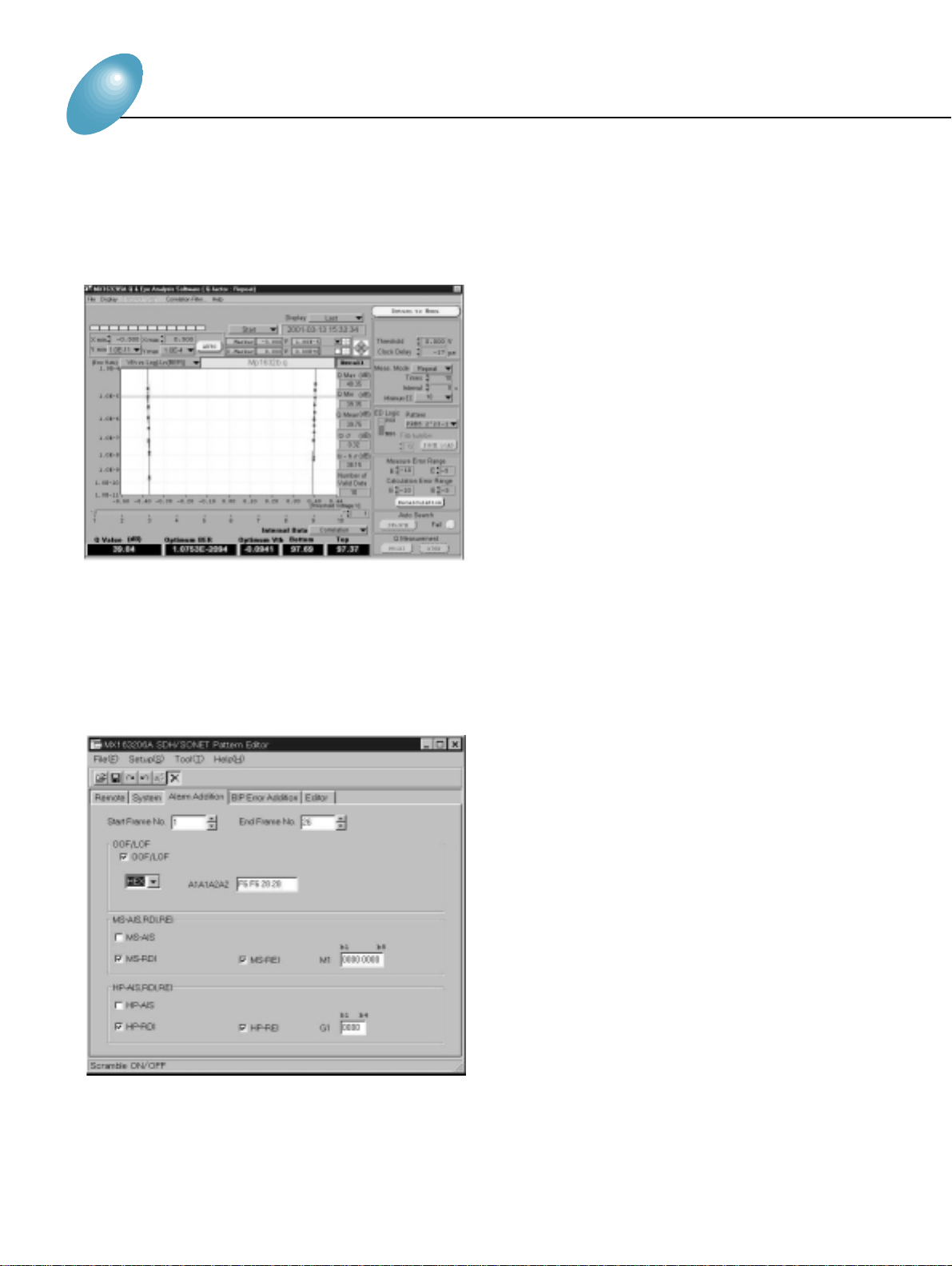
Application Software
■MX163205A Q/Eye Analysis Software
● Eye diagram and eye margin automatic measurement
● Displays a mask figure for the evaluation on the screen
● Q-factor (ITU-T G.976) automatic measurement
■MX163206A SDH/SONET Pattern Editor
● Support OC-1 (STM-0) to OC-48c (STM-1bc) mapping
● Alar m addition (OOF, LOF, MS-AIS, REI, RDI)
● BIP error addition (B1, B2, B3)
● Support "no frame" pattern
Page 9

9
Specifications
Operating frequency 10 MHz to 3.2 GHz (50 MHz to 3.2 GHz when using MP1632C-03 3.2G Internal Synthesizer)
External clock input 0.5 to 2 Vp-p (<0.5 GHz: square wave, ≥0.5 GHz: square wave or sine wave, 50% duty cycle)
Pseudo random pattern (PRBS)
Pattern length: 2
n
–1 (n: 7, 9, 11, 15, 20, 23, 31)
Mark ratio: 1/2, 1/4, 1/8, 0/8, ——1/2, 3/4, 7/8, 8/8
AND bit shift upon mark ratio setting: 1, 3 bits
Data pattern
Generation pattern
Data length: 2 to 8,388,608 bits
Zero substitution pattern
Continuous 0 bit length: 1 to (pattern length – 1) bits
Pattern length: 2n(n: 7, 9, 11, 15)
Error insertion
Error ratio: 10-n(n: 3, 4, 5, 6, 7, 8, 9), single error
External error input: Provided
Number of outputs: 2 (DATA/D—ATA——, independent)
Amplitude: 0.5 to 2 Vp-p (10 mV steps)
Offset voltage
V
OH
:–2 to +2 V (5 mV steps)
Display: VOH, VTH, and VOLselectable
Rise/fall time: ≤80 ps (10% to 90% of amplitude)
Data output Pattern jitter: ≤30 psp-p
Waveform distortion: 10% or 0.1 V of amplitude, whichever is greater
Load impedance: 50 Ω (with back termination)
Connector: SMA
DATA/DD—ATA——tracking:
D—ATA——amplitude and offset voltage can be set to same value as DATA.
Crosspoint adjustment function: Provided
Number of output: 2 (CLOCK/—C—L—O—CK—, independent)
Amplitude: 0.5 to 2 Vp-p (10 mV steps)
Offset voltage
V
OH
: –2 to +2 V (5 mV steps)
Clock output Display: VOH, VTH, and VOLselectable
Rise/fall time: ≤80 ps (10% to 90% of amplitude)
Load impedance: 50 Ω (with back termination)
Connector: SMA
Clock delay: –1 to +1 ns (2 ps steps)
External burst trigger input Input level: 0/–1 V, connector: SMA
Internal burst signal
Burst cycle: 2 µs to 50 ms (1 µs steps)
Enable length: 1 µs to 49.999 ms (1 µs steps)
Burst trigger output Output level: 0/–1 V, connector: SMA
Number of outputs: 1 (1/8 clock, variable pattern synchronization output selectable)
Sync signal output Output level: 0/–1 V
Connector: SMA
Operating temperature +5 to +45°C
Power ≤200 VA
Dimensions and mass 232 (W) x 49 (H) x 449 (D) mm, ≤4.5 O
Operating frequency 10 MHz to 3.2 GHz
Input waveform: NRZ
Input voltage: 0.5 to 4 Vp-p
Data input Variable threshold voltage: –4 to +4 V (1 mV steps)
Ter mination: Connected to GND, –2 V or +3 V via 50 Ω
Connector: SMA
Input waveform: Square wave (<0.5 GHz), square wave or sine wave (≥0.5 GHz), duty: 50%
Input amplitude: 0.5 to 4 Vp-p
Clock input
Variable input delay: –1 to +1 ns (2 ps steps)
Polarity inversion: POS/NEG inversion selectable
Ter mination: Connected to GND, –2 V or +3 V via 50 Ω
Connector: SMA
Auto search function Phase, threshold, PRBS pattern (allowed if the mark ratio is between 1/8 and 7/8)
●MU163220C 3.2G Pulse Pattern Generator
●MU163240C 3.2G Error Detector
Page 10

10
Pseudo random pattern (PRBS)
Pattern length: 2n– 1 (n: 7, 9, 11, 15, 20, 23, 31)
Marker ratio: 1/2, 1/4, 1/8, 0/8, ——1/2, 3/4, 7/8, 8/8
AND bit shift upon marker ratio setting: 1, 3 bits
Receive pattern Data pattern
Data length: 2 to 8,388,608 bits
Zero substitution pattern
Continuous 0 bit length: 1 to (pattern length – 1) bits
Pattern length: 2n(n: 7, 9, 11, 15)
Sync mode Normal, frame
Sync threshold AUTO or 10-n(n: 2, 3, 4, 5, 6, 7, 8)
Error detection mode Omission, insertion, total
Error rate: 0.0000 x 10
-16
to 1.0000 x 10
0
Number of errors: 0 to 9.9999 x 10
16
Measurement items Error interval (async): 0 to 9999999 (Interval: 100 ms, 1 s)
Error free interval (EFI): 0.0000 to 100.0000%
Clock frequency: 0.01 to 3.2 GHz (resolution: 1 Hz, accuracy: 10 ppm ±1 kHz)
Eye margin measurement
Provided
function
Error performance
Provided
calculation function
Measurement channel
1 to 8 channels, each channel settable independently
mask
Number of output: 1 (1/32 bit rate OR error)
Error output Output level: 0/–1 V
Connector: SMA
Number of outputs: 1 (switchable among 1/8 clock, fixed pattern sync, sync gain output)
Sync signal output Output level: 0/–1 V
Connector: SMA
Burst trigger input Input level: 0/–1 V, connector: SMA
Operating temperature +5° to +45°C
Power ≤250 VA
Dimensions and mass 232 (W) x 54 (H) x 449 (D) mm, ≤5 O
OS: Microsoft®Windows®operating system version 3.1
Display: 10.4 inch, color LCD (touch screen), 640 x 480 dots, 256 colors
Printer: Parallel port for external printer (D-sub, 25-pins)
Keyboard: 101 type (English), PS/2 (mini DIN 6-pin connector)
System environment Mouse: Serial, PS/2 (mini DIN, 6-pin connector)
FDD: 2 modes (1.44 MB, 740 KB)
HDD
C drive: ≥474 MB (used for system: measurement data, pattern)
D drive: ≥30 MB (Not accessible to users, interface: IDE)
Remote control RS-232C (standard), GPIB (option): IEEE488.2, Ethernet (option): 10 Base-T
EN61326: 1997/A1: 1998(ClassA),
EMC EN6100-3-2: 1995/A2: 1998(ClassA),
EN61326: 1997/A1: 1998(Annex A)
LVD EN61010: 1993/A2: 1995(Installation Category II, Pollution degree2)
Power supply 100 to 120 Vac/200 to 240 Vac, 47.5 to 63 Hz, ≤150 VA
Operating temperature +5° to +45°C
Dimensions and mass 426 (W) x 221.5 (H) x 451(D) mm, ≤20 O
Frequency range 50 MHz to 3.2 GHz (1 kHz steps)
Frequency accuracy ±2 ppm
SSB phase noise ≤–85 dBc/Hz (10 kHz offset, 1 kHz bandwidth)
Non-harmonic spurious ≤–60 dBc (limited to spurious 10 kHz or more distant from carrier frequency)
Power ≤50 VA
Mass ≤5 O
●MP1632C (Main frame)
●3.2G Internal Synthesizer (Option 03)
Microsoft Windows is a registered trademark of Microsoft Corporation in USA and other countries.
Page 11

11
Computer: IBM-PC/AT or full compatible, OS: Windows 3.1/95/98, CPU: Pentium 133 MHz or higher,
Memory: 32 MB or more,Hard disk space: 25 MB or more
Required system Display
Resolution: 640 x 480 or more, Display colors: 256 or more
FDD: 3.5-inch (1.44 MB)
Text file
A text file describing the program pattern in hex format (maximum number of characters in a line: 32696 bits
including spacesand return characters)
MP1632A/ pattern datafile (PTN)
All the MP1632A/C set data and patterns (file format for reading/writing on the MP1632A/C main screen)
MP1632A/C pattern clipfile (PCP)
Only patterns (a file format that can be read or written in the MP1632A/C Pattern Editor)
●MX163201A TEXT to MP1632A/C Pattern Conversion Software
Note: Since the FD format of MP165X is 1.2 MB, the PC must read 1.2 MB format FD.
Computer: IBM-PC/AT or full compatible, OS: Windows 95/98/NT, CPU: Pentium 166 MHz or higher,
Memory: 64 MB or more, Hard disk space: 100 MB or more,
Required system
GPIB: National Instruments made GPIB interface (PCMCIA-GPIB or AT- GPIB/TNT series boards are recommended.)
Display
Resolution: 800 x 600 or more, Display colors: 256 or more
*If two or more applications are running simultaneously, operation cannot be guaranteed.
Measurement frequency: 1 to 3.2 GHz
Measurement patterns: PRGM, PRBS 7, 9, 11, 15, 20, 23, 31
Pattern format: Continuous/burst (To be synchronized within 1 s)
Eye margin measurement
Measurement resolution (threshold): 1 to 10 mV (1 mV steps), Measurement resolution (phase): 2 to 10 ps (2 ps steps),
Measurement rate: E-2 to E-15
Eye diagram measurement
Function Measurement resolution (phase): 2 to 10 ps (2 ps steps)
Measurement rate: E-2 to E-15 (actual measurement), E-3 to E-12 (estimate measurement)
Display rate: E-2 to E-15 (actual measurement), E-2 to E-4915 (estimate measurement)
Mask test judgment rate: E-2 to E-15
Q factor measurement
Measurement style: Multiple measurements at fixed phase/phase vs. Q factor measurements
Bit error rate range: Upper limit at E-3 to E-5, lower limit at E-7 to E-12
Minimum error count (measurement accuracy): 1, 10, 100, 1000
Vth shift width: Automatic, fixed (1 to 10 mV/1 mV steps)
●MX163205A Q and Eye Analysis Software
Windows is a registered trademark of Microsoft Corporation of the U.S. in the United States and other countries. IBM and AT are Å@registered trademarks ofInternational
Business Machines. Pentium is a registered trademark of Intel Corporation. PCMCIA-GPIB and AT-GPIB/TNT are registered trademarks of NationalInstruments.
Computer: IBM-PC/AT or full compatible, CPU: Pentium 200 MHz or higher, OS: Windows 95/98/NT, Memory: 64 MB or more
Display
Required system Resolution: 800 x 600 or more; Display colors: 256 or more
FDD: 3.5-inch (1.44 MB), Hard disk space: 100 MB or more,
GPIB: National Instruments made GPIB interface (PCMCIA-GPIB or AT-GPIB/TNT series boards are recommended.)
SDH/SONET pattern editor
Mapping: STM-N (N = 1, 4c, 12c, 16c), STS-N SPE (N = 1, 3c, 12c, 48c)
Pattern edit: Arbitrary editing of program patterns (PRBS pattern can be inserted in the payload.), time indication, table indication/edit
Payload:
Free format, ALL 0, ALL 1, PRBS 2 n – 1 (n = 7, 9, 11, 15, 20, 20z, 23, 31) Pattern repetition up to the length of all frames
CID pattern: Available
Functions
Frame repetition : Maximum 26 frames
Alarm addition:
Alarm addition conforming to SDH/SONET Standard
*Items: OOF/LOF, MS-AIS (L-AIS), MS-RDI (L-RDI), MS-REI (L-REI), HP-AIS (P-AIS), HP-REI (P-REI), HP-RDI (P-RDI)
BIP error addition: Generates parity errors of B1, B2, and B3
B1, B2, and B3 calculation: Available
Scramble: Available
BIP correction: Available
OH editor: Available
●MX163206A SDH/SONET Pattern Editor
Computer: IBM-PC/AT or full compatible, OS: Windows 3.1/95/98, CPU: Pentium 133 MHz or higher,
Memory: 32 MB or more,Hard disk space: 25 MB or more
Required system Display
Resolution: 640 x 480 or more, Display colors: 256 or more
FDD: 3.5-inch (1.2/1.44 MB)
Input file
MP165X program pattern files: MP165X’s reading/writing and edit
File name: T.PTN (for pulse patter n generator ), R.PTN (for error detector)
MP1632A/C pattern data file (PTN):
Output file
All the MP1632A/C set data and patterns (file format for reading/writing on the MP1632A/C main screen)
MP1632A/C pattern clip file (PCP): Only patterns (File format that can be read or written in the MP1632A/C’s pat
tern editor.)
●MX163202A MP165X to MP1632A/C Pattern Conversion Software
Page 12

Or dering Information
Please specify model/order number, name and quantity when ordering.
Model/Order No. Name
Main frame
MP1632C Digital Data Analyzer
Standard accessories
Power cord (shielded): 1 pc
F0090 Fuse, 8 A: 2 pcs
Z0319A PS/2 mouse: 1 pc
Z0320 Input pen: 1 pc
Z0396A Pen holder: 1 pc
Z0393 Application disk*
1
: 1 set
Z0395 Remote sample disk*
1
: 1 set
W1859AE MP1632C operation manual: 1 copy
W1860AE MP1632C
remote control operation manual: 1 copy
B0447B Dummy unit to shut EXT unit space: 1 pc
Options
MP1632C-01 GPIB
MP1632C-02 Ethernet
MP1632C-03 3.2G internal synthesizer (50 MHz to 3.2 GHz)
Application software
MX163201A TEXT to MP1632A/C Pattern Conversion Software
MX163202A
MP165X to MP1632A/C Pattern Conversion Software
MX163205A Q and Eye Analysis Software
MX163206A SDH/SONET Pattern Editor
Model/Order No. Name
Peripherals
Z0321A Keyboard (PS/2)
Z0416 3.5 inch head cleaning disk
J0008 GPIB cable, 2 m
MB24B Portable test Rack (specified current: 10 A)
B0348 Soft case
B0329D Front cover(1 MW 5U)
B0333D Rack mount kit
B0447A Dummy unit to shut CG unit space
B0447C Dummy unit to shut PPG unit space
B0447D Dummy unit to shut ED unit space
Z0398 Ethernet installation disk (for Option 02)
W1529AE Ethernet operation manual (for Option 02)
J0905A Semi-rigid cable (for Option 03)
MU163220C 3.2G Pulse Pattern Generator*
2
Standard accessories
J0693A Coaxial cord
(HRM202B
•
3D2W• HRM202B), 1 m: 1 pc
J0696A Coaxial cord (AA-165-500), 0.5 m: 2 pcs
W1857AE MU163220C/163240C operation manual: 1 copy
Z0306A Wrist strap: 1 pc
MU163240C 3.2G Error Detector*
2
Standard accessories
J0693A Coaxial cord
(HRM202B
•
3D2W• HRM202B), 1 m: 1 pc
J0696A Coaxial cord (AA-165-500), 0.5 m: 2 pcs
W1857AE MU163220C/163240C
operation manual*
3
: 1 copy
*1Only for MP1632C customer
*
2
Units are factory options (not user replaceable).
*
3
Not supplied when 3.2G Pulse Pattern Generator purchased as same time
Catalog No. MP1632C-E- A - 1 - (3.00) Pr inted in Japan 2002-6 30NDL
ANRITSU CORPORATION
MEASUREMENT SOLUTIONS
5-10-27, Minamiazabu, Minato-ku, Tokyo106-8570, Japan
Phone: +81-3-3446-1111
Telex: J34372
Fax: +81-3-3442-0235
•
U.S.A.
ANRITSU COMPANY
North American Region Headquarters
1155 East Collins Blvd., Richardson, Tx 75081, U.S.A.
Toll Free: 1-800 - ANRITSU (267 - 4878)
Phone: +1-972- 644 - 1777
Fax: +1-972 - 671 - 1877
•
Canada
ANRITSU ELECTRONICS LTD.
700 Silver Seven Road, Suite 120, Kanata,
ON K2V 1C3, Canada
Phone: +1-613-591-2003
Fax: +1-613-591-1006
•
Brasil
ANRITSU ELETRÔNICA LTDA.
Praia de Botafogo 440, Sala 2401 CEP 22250-040,
Rio de Janeiro, RJ, Brasil
Phone: +55-21 - 5276922
Fax: +55-21 - 537 - 1456
•
U.K.
ANRITSU LTD.
200 Capability Green, Luton, Bedfordshire LU1 3LU, U.K.
Phone: +44-1582 - 433200
Fax: +44-1582 - 731303
•
Germany
ANRITSU GmbH
Grafenberger Allee 54-56, 40237 Düsseldorf, Germany
Phone: +49-211 - 96855 - 0
Fax: +49-211 - 96855 - 55
•
France
ANRITSU S.A.
9, Avenue du Québec Z.A. de Courtabœuf 91951 Les
Ulis Cedex, France
Phone: +33-1 - 60 - 92 - 15 - 50
Fax: +33-1 - 64 - 46 - 10 - 65
•
Italy
ANRITSU S.p.A.
Via Elio Vittorini, 129, 00144 Roma EUR, Italy
Phone: +39-06 - 509 - 9711
Fax: +39-06 - 502 - 24 - 25
•
Sweden
ANRITSU AB
Botvid Center, Fittja Backe 1-3 145 84 Stockholm,
Sweden
Phone: +46-853470700
Fax: +46-853470730
•
Spain
ANRITSU ELECTRÓNICA, S.A.
Europa Empresarial Edificio Londres, Planta 1, Oficina
6 C/ Playa de Liencres, 2 28230 Las Rozas. Madrid,
Spain
Phone: +34-91 - 6404460
Fax: +34-91 - 6404461
•
Singapore
ANRITSU PTE LTD.
10, Hoe Chiang Road #07-01/02, Keppel Towers,
Singapore 089315
Phone: +65-6282-2400
Fax: +65-6282-2533
•
Hong Kong
ANRITSU COMPANY LTD.
Suite 719, 7/F., Chinachem Golden Plaza, 77 Mody
Road, Tsimshatsui East, Kowloon, Hong Kong, China
Phone: +852-2301 - 4980
Fax: +852-2301 - 3545
•
Korea
ANRITSU CORPORATION
14F Hyun Juk Bldg. 832-41, Yeoksam-dong,
Kangnam-ku, Seoul, Korea
Phone: +82-2 - 553 - 6603
Fax: +82-2 - 553 - 6604
˜
5
•
Australia
ANRITSU PTY LTD.
Unit 3/170 Forster Road Mt. Waver ley, Victoria, 3149,
Australia
Phone: +61-3 - 9558 - 8177
Fax: +61-3 - 9558 - 8255
•
Taiwan
ANRITSU COMPANY INC.
6F, 96, Sec. 3, Chien Kou North Rd. Taipei, Taiwan
Phone: +886-2 - 2515 - 6050
Fax: +886-2 - 2509 - 5519
Specifications are subject to change without notice.
 Loading...