

Page 1

User Guide
MA8100A
®
NEON
Signal Mapper
You must have an Android™ smart phone or tablet and an email
address that you will use to sign in to the NEON application. Basic
familiarity with Anritsu handheld spectrum analyzers is required.
Anritsu Company
490 Jarvis Drive
Morgan Hill, CA 95037-2809
USA
http://www.anritsu.com
Part Number: 10580-00422
Copyright 2019 Anritsu Company, USA. All Rights Reserved.
Published: November 2019
Revision: D
Page 2

TRADEMARK ACKNOWLEDGMENTS
LMR Master, Spectrum Master, Site Master, BTS Master, Cell Master, and VNA Master are trademarks of Anritsu
Company.
The NEON trademark is wholly owned by TRX Systems, Inc. Use of the NEON trademark without permission of TRX
Systems is prohibited.
The Android name and logo are property of Google LLC. You may not use the logo or the logo’s custom typeface. You may use
the word “Android” in a product name only as a descriptor, such as “for Android” and the first instance should be followed by
a TM symbol, “for Android™.”
Legal Notice | Android Developers
SAMSUNG is a trademark of SAMSUNG in the United States or other countries.
Windows is a registered trademark of Microsoft Corporation.
Page 3

Table of Contents
Chapter 1—Overview
1-1 Introduction . . . . . . . . . . . . . . . . . . . . . . . . . . . . . . . . . . . . . . . . . . . . . . . . . . . . . . . . . . . . . . . . 1-1
Contacting Anritsu for Sales and Service . . . . . . . . . . . . . . . . . . . . . . . . . . . . . . . . . . . . . . 1-1
1-2 System Overview . . . . . . . . . . . . . . . . . . . . . . . . . . . . . . . . . . . . . . . . . . . . . . . . . . . . . . . . . . . 1-1
1-3 NEON Command Software. . . . . . . . . . . . . . . . . . . . . . . . . . . . . . . . . . . . . . . . . . . . . . . . . . . . 1-2
1-4 NEON Signal Mapper Software . . . . . . . . . . . . . . . . . . . . . . . . . . . . . . . . . . . . . . . . . . . . . . . . 1-2
1-5 NEON Tracking Unit . . . . . . . . . . . . . . . . . . . . . . . . . . . . . . . . . . . . . . . . . . . . . . . . . . . . . . . . . 1-2
LED Indicators . . . . . . . . . . . . . . . . . . . . . . . . . . . . . . . . . . . . . . . . . . . . . . . . . . . . . . . . . . . 1-3
On/Off Procedure . . . . . . . . . . . . . . . . . . . . . . . . . . . . . . . . . . . . . . . . . . . . . . . . . . . . . . . . 1-3
Calibration . . . . . . . . . . . . . . . . . . . . . . . . . . . . . . . . . . . . . . . . . . . . . . . . . . . . . . . . . . . . . . 1-3
1-6 NEON Cloud Service . . . . . . . . . . . . . . . . . . . . . . . . . . . . . . . . . . . . . . . . . . . . . . . . . . . . . . . . 1-4
1-7 Spectrum Analyzer . . . . . . . . . . . . . . . . . . . . . . . . . . . . . . . . . . . . . . . . . . . . . . . . . . . . . . . . . . 1-4
1-8 Basic Workflow . . . . . . . . . . . . . . . . . . . . . . . . . . . . . . . . . . . . . . . . . . . . . . . . . . . . . . . . . . . . . 1-4
Chapter 2—Installation
2-1 System Requirements . . . . . . . . . . . . . . . . . . . . . . . . . . . . . . . . . . . . . . . . . . . . . . . . . . . . . . . 2-1
NEON Command System Requirements for the PC . . . . . . . . . . . . . . . . . . . . . . . . . . . . . . 2-1
Android System Requirements . . . . . . . . . . . . . . . . . . . . . . . . . . . . . . . . . . . . . . . . . . . . . . 2-1
2-2 Registration and Installation . . . . . . . . . . . . . . . . . . . . . . . . . . . . . . . . . . . . . . . . . . . . . . . . . . . 2-1
NEON Command Software . . . . . . . . . . . . . . . . . . . . . . . . . . . . . . . . . . . . . . . . . . . . . . . . . 2-1
NEON Signal Mapper Software. . . . . . . . . . . . . . . . . . . . . . . . . . . . . . . . . . . . . . . . . . . . . . 2-3
2-3 Software Update . . . . . . . . . . . . . . . . . . . . . . . . . . . . . . . . . . . . . . . . . . . . . . . . . . . . . . . . . . . . 2-4
Chapter 3—Site Planning
3-1 Log In to NEON Command. . . . . . . . . . . . . . . . . . . . . . . . . . . . . . . . . . . . . . . . . . . . . . . . . . . . 3-1
3-2 Create a Building . . . . . . . . . . . . . . . . . . . . . . . . . . . . . . . . . . . . . . . . . . . . . . . . . . . . . . . . . . . 3-1
3-3 Edit a Building in NEON Command . . . . . . . . . . . . . . . . . . . . . . . . . . . . . . . . . . . . . . . . . . . . . 3-3
Building Editor Toolbox . . . . . . . . . . . . . . . . . . . . . . . . . . . . . . . . . . . . . . . . . . . . . . . . . . . . 3-3
Add Floors to a Building . . . . . . . . . . . . . . . . . . . . . . . . . . . . . . . . . . . . . . . . . . . . . . . . . . . 3-4
Add a Floor Plan . . . . . . . . . . . . . . . . . . . . . . . . . . . . . . . . . . . . . . . . . . . . . . . . . . . . . . . . . 3-5
3-4 Offline Buildings (Optional Feature) . . . . . . . . . . . . . . . . . . . . . . . . . . . . . . . . . . . . . . . . . . . . . 3-8
Export a Mapping Package . . . . . . . . . . . . . . . . . . . . . . . . . . . . . . . . . . . . . . . . . . . . . . . . . 3-8
Import a Mapping Package into NEON Command . . . . . . . . . . . . . . . . . . . . . . . . . . . . . . . 3-8
Upload a Mapping Package to Android Device . . . . . . . . . . . . . . . . . . . . . . . . . . . . . . . . . . 3-8
3-5 Edit a Building in Signal Mapper. . . . . . . . . . . . . . . . . . . . . . . . . . . . . . . . . . . . . . . . . . . . . . . 3-10
Chapter 4—On-Site Mapping
4-1 Select the Building and Floor . . . . . . . . . . . . . . . . . . . . . . . . . . . . . . . . . . . . . . . . . . . . . . . . . . 4-1
4-2 Pair the Tracking Unit and Android Device. . . . . . . . . . . . . . . . . . . . . . . . . . . . . . . . . . . . . . . . 4-1
NFC Touch Pairing . . . . . . . . . . . . . . . . . . . . . . . . . . . . . . . . . . . . . . . . . . . . . . . . . . . . . . . 4-1
Tracking Unit Selection in Signal Mapper . . . . . . . . . . . . . . . . . . . . . . . . . . . . . . . . . . . . . . 4-2
4-3 Initialize Your Location with Signal Mapper . . . . . . . . . . . . . . . . . . . . . . . . . . . . . . . . . . . . . . . 4-4
MA8100A UG PN: 10580-00422 Rev. D Contents-1
Page 4

Table of Contents (Continued)
4-4 Select Signal Filter Type . . . . . . . . . . . . . . . . . . . . . . . . . . . . . . . . . . . . . . . . . . . . . . . . . . . . . . 4-6
4-5 Channel Power Measurement with Spectrum Analyzer . . . . . . . . . . . . . . . . . . . . . . . . . . . . . . 4-6
4-6 Connect Anritsu Device to Signal Mapper . . . . . . . . . . . . . . . . . . . . . . . . . . . . . . . . . . . . . . . . 4-8
4-7 On-Site Mapping . . . . . . . . . . . . . . . . . . . . . . . . . . . . . . . . . . . . . . . . . . . . . . . . . . . . . . . . . . . . 4-9
4-8 Signal Mapping in an Offline Building . . . . . . . . . . . . . . . . . . . . . . . . . . . . . . . . . . . . . . . . . . . 4-10
4-9 Signal Maps Stored on Android Device . . . . . . . . . . . . . . . . . . . . . . . . . . . . . . . . . . . . . . . . . 4-12
Upload Stored Signal Maps to the Cloud. . . . . . . . . . . . . . . . . . . . . . . . . . . . . . . . . . . . . . 4-12
Transfer Stored Signal Maps to a PC . . . . . . . . . . . . . . . . . . . . . . . . . . . . . . . . . . . . . . . . 4-13
Chapter 5—Signal Map Viewing and Reporting
5-1 Open a Signal Map Log . . . . . . . . . . . . . . . . . . . . . . . . . . . . . . . . . . . . . . . . . . . . . . . . . . . . . . 5-1
5-2 Create a Combined Signal Map . . . . . . . . . . . . . . . . . . . . . . . . . . . . . . . . . . . . . . . . . . . . . . . . 5-2
5-3 Generate a Heat Map . . . . . . . . . . . . . . . . . . . . . . . . . . . . . . . . . . . . . . . . . . . . . . . . . . . . . . . . 5-2
5-4 Create Reports . . . . . . . . . . . . . . . . . . . . . . . . . . . . . . . . . . . . . . . . . . . . . . . . . . . . . . . . . . . . . 5-4
CSV Report . . . . . . . . . . . . . . . . . . . . . . . . . . . . . . . . . . . . . . . . . . . . . . . . . . . . . . . . . . . . . 5-4
Image Report . . . . . . . . . . . . . . . . . . . . . . . . . . . . . . . . . . . . . . . . . . . . . . . . . . . . . . . . . . . . 5-4
iBwave Report . . . . . . . . . . . . . . . . . . . . . . . . . . . . . . . . . . . . . . . . . . . . . . . . . . . . . . . . . . . 5-4
5-5 NEON Command Display Settings . . . . . . . . . . . . . . . . . . . . . . . . . . . . . . . . . . . . . . . . . . . . . . 5-4
Maps Menu . . . . . . . . . . . . . . . . . . . . . . . . . . . . . . . . . . . . . . . . . . . . . . . . . . . . . . . . . . . . . 5-5
Layers Menu . . . . . . . . . . . . . . . . . . . . . . . . . . . . . . . . . . . . . . . . . . . . . . . . . . . . . . . . . . . . 5-5
Color Maps . . . . . . . . . . . . . . . . . . . . . . . . . . . . . . . . . . . . . . . . . . . . . . . . . . . . . . . . . . . . . 5-5
Preferences . . . . . . . . . . . . . . . . . . . . . . . . . . . . . . . . . . . . . . . . . . . . . . . . . . . . . . . . . . . . . 5-9
Contents-2 PN: 10580-00422 Rev. D MA8100A UG
Page 5
Chapter 1 — Overview
1-1 Introduction
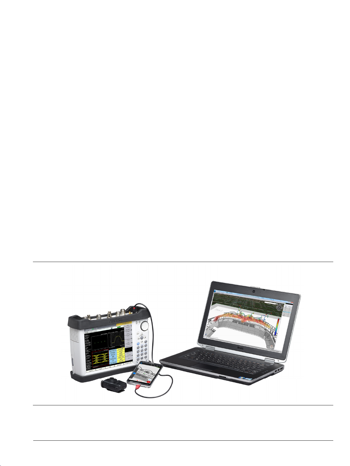
The MA8100A NEON® Signal Mapper is a 3D in-building coverage mapping solution that is integrated for use
with Anritsu handheld spectrum analyzer products to automatically collect geo-referenced test data with every
step. The system allows you to perform coverage testing of RF communications systems both indoors and
outdoors. It uses inertial data from a wearable tracking device to enable real-time 3D location and mapping
inside buildings. The system incorporates GPS data when line of sight to GPS satellites is available.
Contacting Anritsu for Sales and Service
To contact Anritsu, visit the following URL and select the services in your region:
http://www.anritsu.com/contact-us.
1-2 System Overview
The MA8100A consists of the following software and hardware from TRX Systems, a third-party partner of
Anritsu:
• NEON Command Software for a Windows-based PC or laptop
• NEON Signal Mapper Software for Android phone or tablet
• NEON Tracking Unit with micro USB cable for charging the battery
• NEON Cloud Service
The user is expected to provide an Anritsu spectrum analyzer test instrument, Android device, and a PC or
laptop in order to perform coverage mapping of RF signal data using NEON Signal Mapper.
A USB OTG cable is included for connecting the Anritsu instrument to your Android device.
Figure 1-1. MA8100A NEON Signal Mapper Solution
MA8100A UG PN: 10580-00422 Rev. D 1-1
Page 6
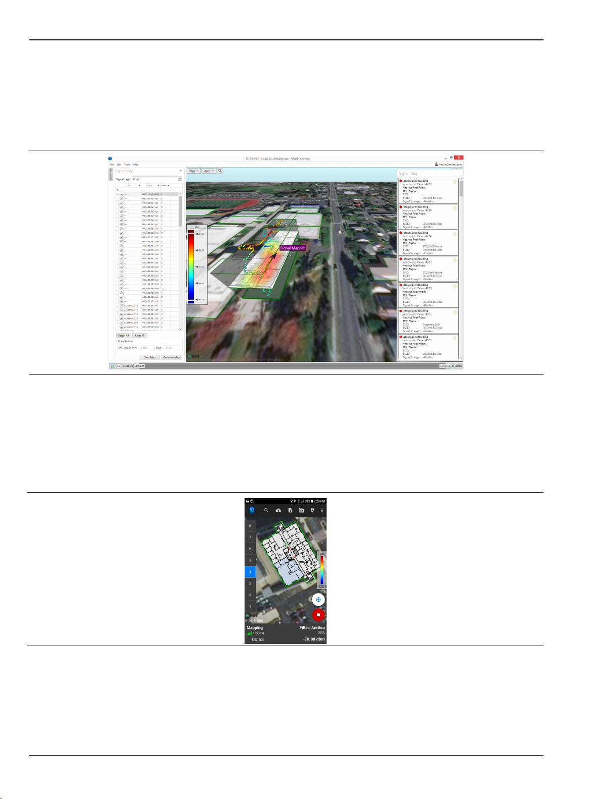
1-3 NEON Command Software Overview
1-3 NEON Command Software
The NEON Command Software is a PC-based map editing and tracking application that enables the creation
and visualization of 3D building maps and provides centralized access to the NEON Cloud Service to store and
retrieve maps and measurement data. It allows the user to create building outlines, add floor plans, and
generate heat maps of geo-referenced measurement results. The file export feature lets you generate reports of
the signal map data.
Figure 1-2. NEON Command Interface (PC)
1-4 NEON Signal Mapper Software
The NEON Signal Mapper Software provides the Android user interface to test signal coverage and to create
heat maps. RF data is captured by an Anritsu Handheld Spectrum Analyzer and sent to the Android device,
typically via a USB connection. Users can edit building data, initialize their location, start and stop the
recording of signal data, and upload mapping data to the NEON Cloud.
Figure 1-3. NEON Signal Mapper Interface (Android phone)
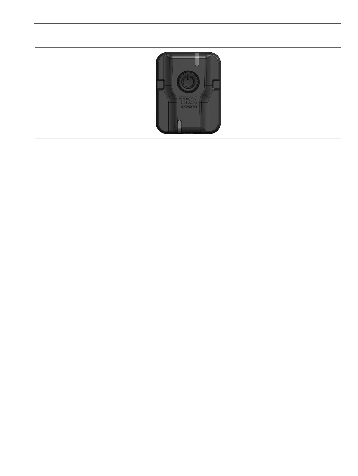
1-5 NEON Tracking Unit
The NEON Tracking Unit can be referred to as Tracker, Tracking Accessory, or Tracking Device. It is a small,
wearable accessory used to collect 3D location information. The location data is sent over Bluetooth to the
NEON Signal Mapper application running on an Android phone or tablet.
1-2 PN: 10580-00422 Rev. D MA8100A UG
Page 7
Overview 1-5 NEON Tracking Unit
A micro USB cable is provided for recharging the unit battery.
Figure 1-4. NEON Tracking Unit
LED Indicators
The NEON Tracking Unit has two LEDs to indicate the device status. The indicator at the top of the unit
shows the accessory’s operating mode. The bottom LED indicates the charging status.
Operation LED (Top)
• Off – Tracking Unit is powered off
• Solid green – Starting up or powering down
• Blinking green – Anchor mode: device is on but not connected to the Signal Mapper app
• Blinking blue – Tracker mode, connected to NEON
• Blinking orange – Tracker mode, not connected to NEON
• Blinking purple – Bootloader starting or download in progress
• Solid purple – Bootloader Ready
• Solid green – Bootloader Success
Charging LED (Bottom)
• Solid orange – Charging
• Solid green – Charged
• Off – USB is disconnected
• Blinking green/orange – Charging error
On/Off Procedure
Press the Tracking Unit power button to turn on the device. The top LED is solid green while the unit is
powering on. It blinks green when power-on is complete and the Tracker is not yet connected to the Signal
Mapper application (Anchor mode).
To turn off the Tracking Unit, press and hold the power button for at least a half-second. The top LED is solid
green while the unit is powering down and turns off when power down is complete.
Calibration
The NEON Tracking Unit requires no user calibration. The magnetometer and gyroscope within the device will
automatically calibrate while the user moves and stops.
MA8100A UG PN: 10580-00422 Rev. D 1-3
Page 8
1-6 NEON Cloud Service Overview
1-6 NEON Cloud Service
Signal map logs containing measurement results with location information for the signals that were detected
and geo-referenced are uploaded to the NEON Cloud, where they are accessible to users registered under the
same NEON subscription.
Building data is also uploaded to the cloud when saved, except for offline buildings. Refer to “Offline Buildings
(Optional Feature)”. You can download building updates made by other users by synchronizing NEON
Command or Signal Mapper with the cloud.
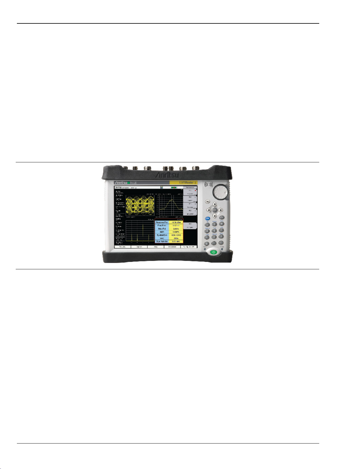
1-7 Spectrum Analyzer
The Signal Mapper application accepts channel power measurements from RF signal test equipment. Anritsu
handheld test instruments that support Spectrum Analyzer mode include these product families: LMR Master,
Spectrum Master, Site Master, BTS Master, Cell Master, and VNA Master.
The MA8100A brings to Anritsu’s handheld spectrum analyzer products the additional ability to perform
coverage mapping of RF signal data inside buildings, where GPS is not available.
Figure 1-5. Anritsu Handheld Spectrum Analyzer (not included)
1-8 Basic Workflow
The following is a summary of the basic tasks involved in installing and registering for NEON and performing
site planning and mapping. In a typical installation, tasks 1 through 4 are performed by the primary user or
administrator responsible for managing the NEON subscription and user accounts. For coverage mapping,
users in the field may start with Step 5.
1. Activate your NEON subscription and create a NEON account.
2. Depending on the number of licenses purchased, you can invite additional users to join the subscription
by registering for their own login accounts.
3. Download and install NEON Command on your PC.
4. Perform site planning by creating a building outline and adding a floor plan to each floor, then save the
building model.
5. Log in to the Signal Mapper app on your Android phone or tablet.
If you have not yet installed Signal Mapper, go to https://neon.trxsystems.com to open the NEON login
page, then download and install the app. You must first register for NEON if you are a new user.
6. Pair the NEON Tracking Unit and Android device.
7. Select the building and floor that you want to map.
1-4 PN: 10580-00422 Rev. D MA8100A UG
Page 9
Overview 1-8 Basic Workflow
8. Initialize your location.
9. Connect the Android device to the Anritsu handheld instrument, using the USB OTG cable provided.
10. Set the test instrument to Spectrum Analyzer mode and turn on channel power measurements.
11. Select the signal type you want to map.
12. Start signal mapping and walk through the areas where you want to collect data.
13. When finished, upload the signal map to the NEON Cloud.
14. Open the cloud signal map in NEON Command on your PC.
15. Select the signal type to display, then click Generate Map to view a heat map of the signal strength along
the plotted path.
16. Click on a colored dot to see a more detailed view of the signal data.
17. Optionally create reports for the signal map.
Not all of the tasks listed above have to be performed in the exact sequence presented. For
Note
example, you can start the channel power measurements on the Anritsu Spectrum Analyzer
before connecting the instrument to your Android device and pairing the latter with the NEON
Tracking Unit.
MA8100A UG PN: 10580-00422 Rev. D 1-5
Page 10

1-8 Basic Workflow Overview
1-6 PN: 10580-00422 Rev. D MA8100A UG
Page 11

Chapter 2 — Installation
2-1 System Requirements
Coverage mapping of RF data captured with an Anritsu Handheld Spectrum Analyzer requires the use of a PC
and an Android smart phone or tablet. The spectrum analyzer test instrument, PC, and Android device are not
included in the MA8100A product bundle and must be provided by the user.
NEON Command System Requirements for the PC
• Operating system: Windows 7/8/10 with .NET Framework 4.6.2
• Memory: 4 GB RAM or higher
• Processor: Dual Core 2.0 GHz or higher
• Graphics: Hardware must support OpenGL 3.0 or later
Android System Requirements
• API level: 19 or higher
• Model: Recommended Samsung Galaxy S7
• Operating system: Android OS v5.0 or later
• Memory: Recommended 2GB RAM or higher
• Processor: Recommended Quad Core 1.9 GHz or higher
2-2 Registration and Installation
Follow the instructions given in the next sections to register for NEON and to install the software. NEON
Command is installed on a PC that will serve as Command Station, while NEON Signal Mapper is an Android
app. The maximum number of licensed Command Stations and Android devices depends on the MA8100A
NEON Signal Mapper subscription that your company purchased.
NEON Command Software
Begin with Step 1 only if you have an activation code and your company’s NEON subscription has not yet been
activated. Otherwise, start with Step 3.
1. Open a Web browser on your PC and go to https://neon.trxsystems.com/account/activate.
Alternatively, if you received an email with the subject line “Welcome to NEON!”, click the Activate
NEON button in the email and you will be redirected to the NEON activation page.
2. Enter your activation code and company name, then click Activate.
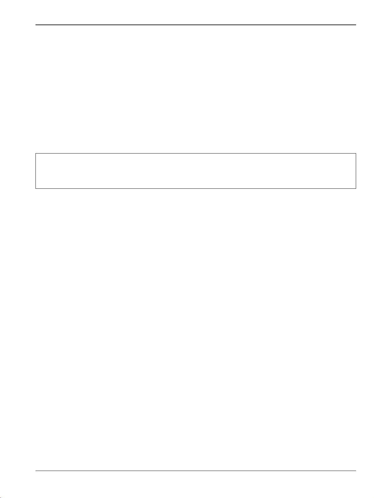
3. To register for NEON, enter a user name to be associated with this account in the Create a NEON
Account window. If you already have a NEON login account, skip this step and go to Step 6.
MA8100A UG PN: 10580-00422 Rev. D 2-1
Page 12
2-2 Registration and Installation Installation
4. Enter your email address and create a password, then click Sign Up.
Figure 2-1. NEON Account Registration
5. To complete creating your account, open the email titled “NEON Email Address Verification” and click
the Verify Email Address link.
6. Enter https://neon.trxsystems.com in your browser to open the login page. Alternatively, you can click
the Login Now button if present.
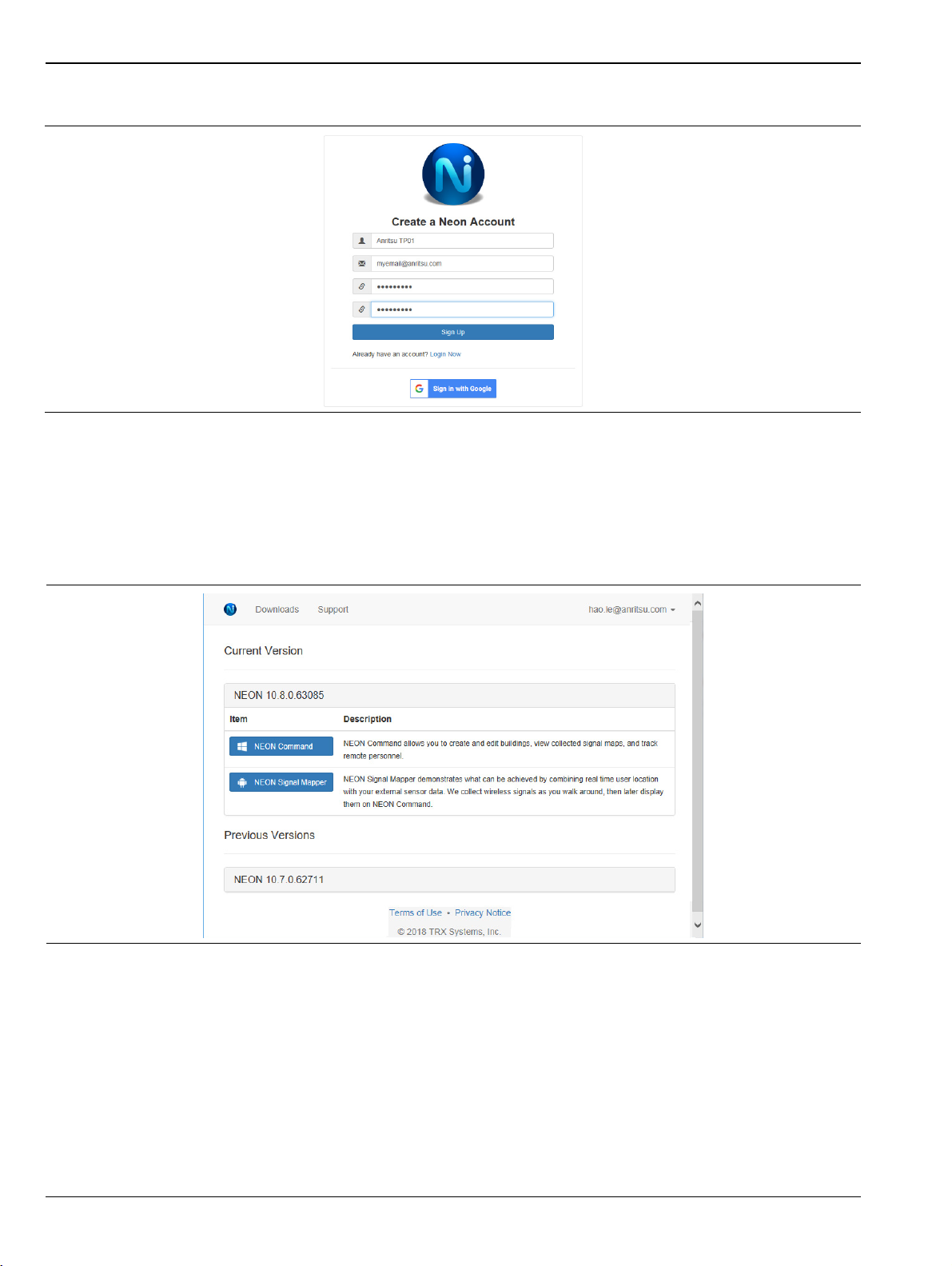
7. Log in to the account you created. The NEON Downloads page will open.
Figure 2-2. NEON Software Downloads Page
8. Click the NEON Command button to download the software. You can choose to run or save a local copy of
the installer. Your Web browser may display a warning message that the file is not safe.
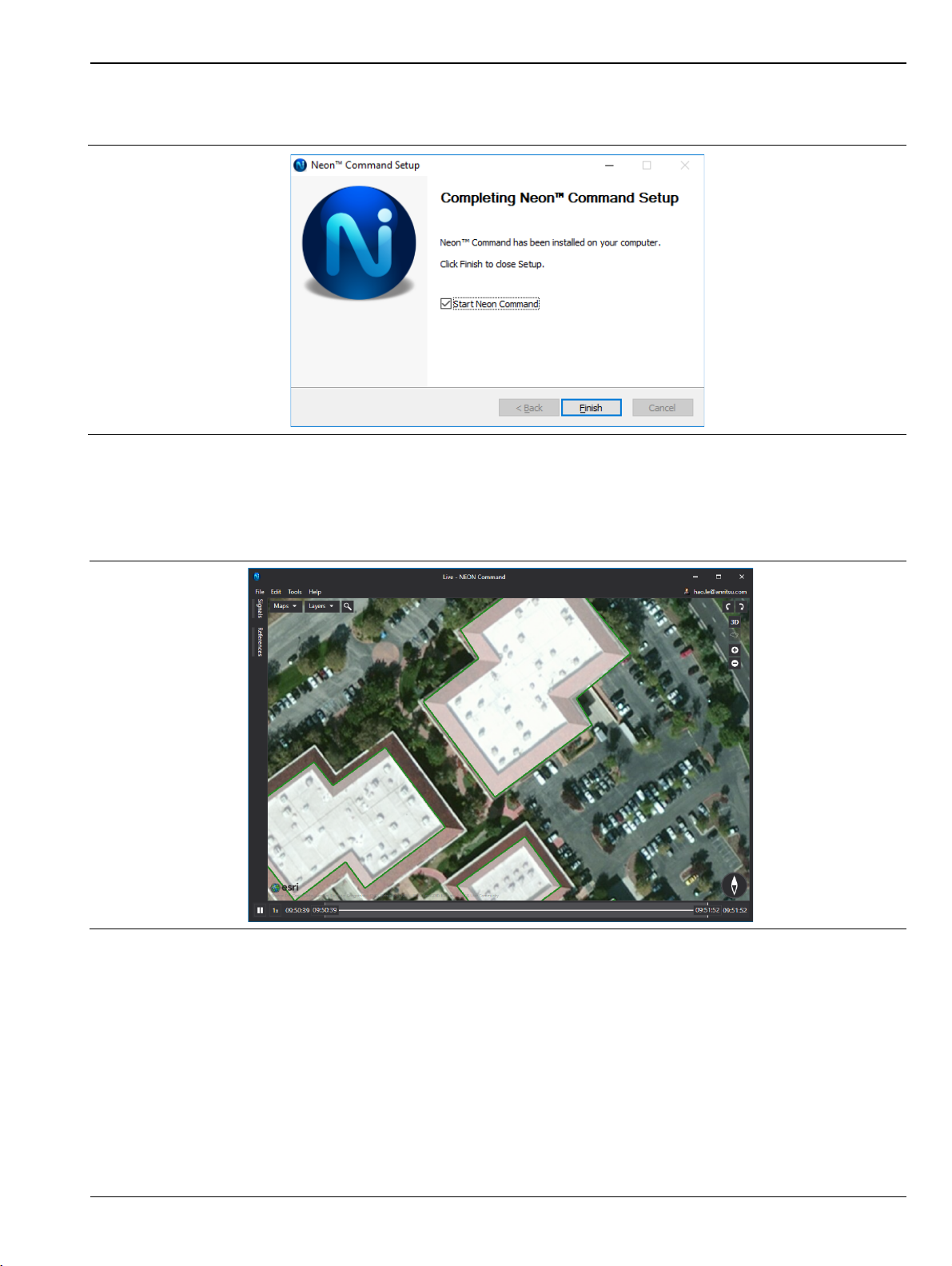
9. The NEON Command Setup wizard will guide you through the software installation. Click Finish to close
Setup.
2-2 PN: 10580-00422 Rev. D MA8100A UG
Page 13
Installation 2-2 Registration and Installation
By default, the Start NEON Command box is checked and the application will launch if the installation is
successful.
Figure 2-3. Finish NEON Command Setup
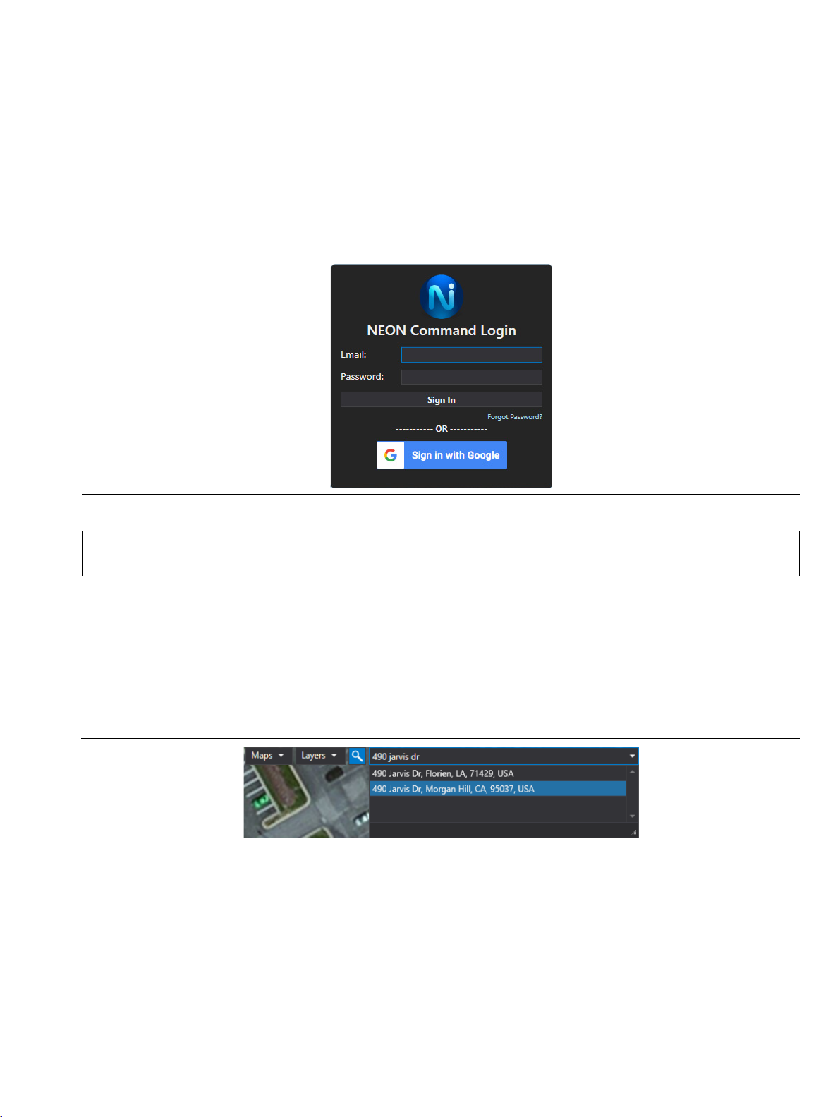
10. Log in to your NEON account.
The NEON Command window will display a satellite view (the default) of the testing area. Your email
address appears in the top right corner of the window.
Figure 2-4. NEON Command Window
NEON Signal Mapper Software
If you received an email with the subject line “Welcome to NEON!” inviting you to join your company’s NEON
subscription, click the Register for NEON button in the email and create your login account as described in
Step 3 through Step 5 under “NEON Command Software”.
Proceed with the steps below after you have registered for a login account.
1. Open a Web browser on your Android device and go to https://neon.trxsystems.com.
2. Log in to your NEON account.
MA8100A UG PN: 10580-00422 Rev. D 2-3
Page 14

2-3 Software Update Installation
3. On the Downloads page, tap the NEON Signal Mapper button. See Figure 2-2 on page 2-2.
4. Install the Signal Mapper application by tapping the file from the drop-down notification bar. You can
also install the app from the Downloads folder on your Android device.
2-3 Software Update
Registered users should receive an email from TRX Systems announcing a new software version when one
becomes available. Click on the included link to open the login page and you will be directed to the NEON
Downloads page.
Alternatively, you can simply open the application and a prompt will display, asking whether you wish to
update. Follow the screen prompts to update to the latest version.
With no update notification, you can still look for the latest versions of NEON Command and NEON Signal
Mapper by logging in to the Downloads page at https://neon.trxsystems.com. If you already have NEON
Command open on your PC, click the Help menu and select Check for Updates. On your Android device, tap the
Signal Mapper menu button and select Check for Updates.
2-4 PN: 10580-00422 Rev. D MA8100A UG
Page 15
Chapter 3 — Site Planning
3-1 Log In to NEON Command
The login page opens when you launch NEON Command on your PC, unless you are already signed in. Use
your registered email address and password to log in to the application. If you are using a Gmail address, you
can alternatively click on Sign in with Google.
Figure 3-1. NEON Command Login
Note
To log out of NEON Command, click your email address in the upper right corner of the screen and select
Logout.
Exiting NEON Command does not log you out. Next time you open the application, you will still be
logged in and the login page will be bypassed.
3-2 Create a Building
1. Click the Search icon in the NEON Command window and enter the street address of the building where
you want to map signals. You may be able to choose from a list of matching addresses.
Figure 3-2. Enter Building Address
2. Click and drag the map and zoom in or out as needed to center the building in the aerial view.
MA8100A UG PN: 10580-00422 Rev. D 3-1
Page 16
3-2 Create a Building Site Planning
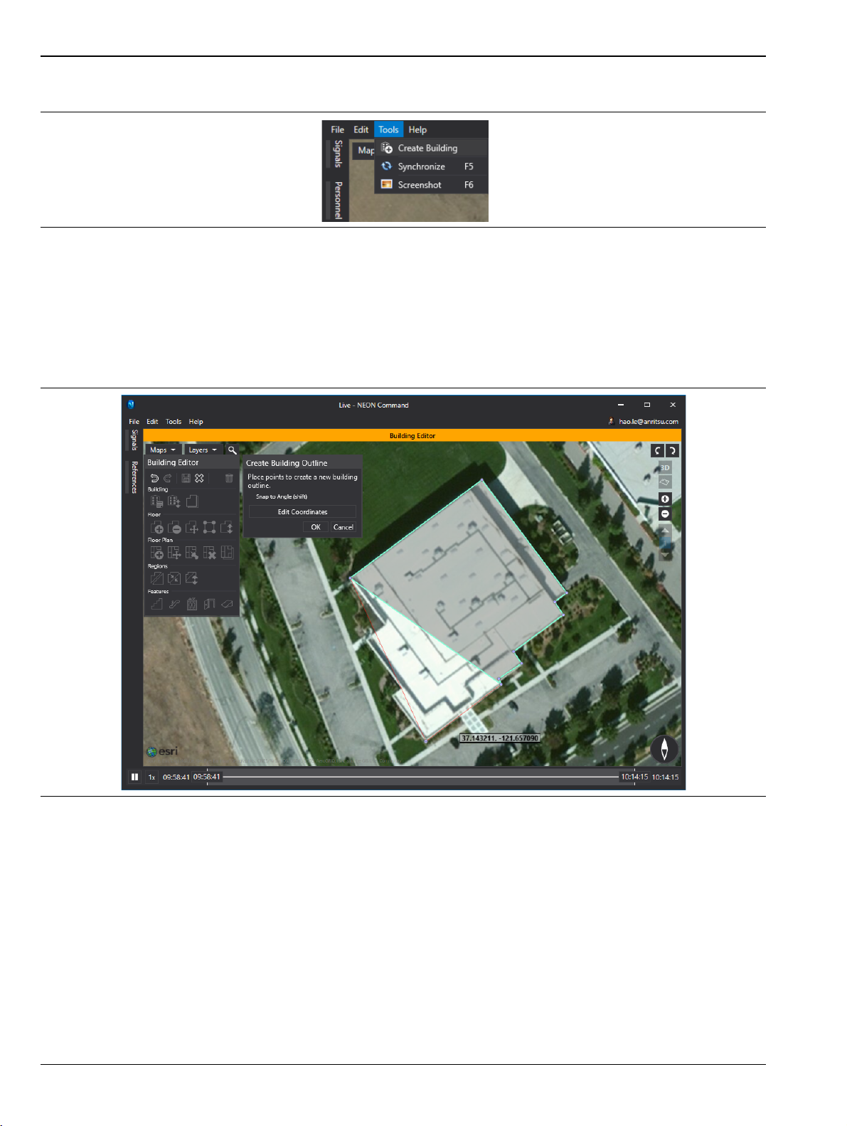
3. Select Create Building from the Tools menu.
Figure 3-3. Create Building
Alternatively, you can right-click on the map and select Create Building from the pop-up menu.
4. Sketch the building outline by clicking on each corner of the building in the satellite imagery.
5. After clicking the last vertex of the outline, click OK (or press Enter on the keyboard) to apply the
polygon.
To cancel building creation, click Cancel or press Esc.
Figure 3-4. Sketch Building Outline
6. When the building outline is complete, NEON Command automatically enters Building Editor mode and
the Edit Building Details dialog opens.
Continue with Step 2 on page 3-4 to enter building information.
3-2 PN: 10580-00422 Rev. D MA8100A UG
Page 17

Site Planning 3-3 Edit a Building in NEON Command
3-3 Edit a Building in NEON Command
The NEON Command Building Editor features let you name a building, add floors and floor plans, and edit the
building outline and floor plans. Optionally, you can download any building updates made by another user by
selecting Synchronize from the Tools menu.
Building Editor Toolbox
To enter Building Editor mode, right-click on a previously created outline and select Edit Building from the
pop-up menu. If you just finished creating a building, NEON Command automatically displays the Edit
Building Details dialog illustrated in Figure 3-9.
Figure 3-5. Building Editor Toolbox
While in Building Editor mode, you can access the same edit functions available in the toolbox by right-clicking
the building outline and selecting the function from the pop-up menu.
Figure 3-6. Building Editor Pop-Up Menu
The Building Editor is also available in the NEON Signal Mapper app on your Android device. Refer to “Edit a
Building in Signal Mapper” on page 3-10.
MA8100A UG PN: 10580-00422 Rev. D 3-3
Page 18

3-3 Edit a Building in NEON Command Site Planning
General
•Undo – Annuls the previous user action. This functionality is not available with all actions.
•Redo – Performs the previous user action that was canceled with Undo.
•Save – Ends the editing session and retains all changes.
•Discard – Ends the editing session without saving pending changes, if any.
•Delete – Deletes the currently selected building and all contained items from the user’s subscription and
ends the editing session.
Note
Figure 3-7. Building Editor Tools - General
Building
• Edit Building Details – Opens the Building Details dialog where you can set or change the building
name, specify the number of floors above and below ground, and assign a number or label to each floor.
• Raise/Lower Building – Raises or lowers a building to better match its entrances to the terrain. This
action only affects the display – which automatically changes to 3D view – and is not necessary to
improve tracking accuracy.
• Copy Floor Layout to Other Floors – Copies the outline and regions of the selected floor to any other
floor in the building.
Hover your mouse pointer over a toolbox icon to view a tool tip with a short description of the tool’s
function. See Figure 3-7.
Add Floors to a Building
After creating a building outline, you can give the building a name and set the number of floors in the building.
Perform the following steps while in Building Editor mode.
1. If the Edit Building Details dialog is not currently open, click the Edit Building Details icon in the Building
Editor toolbox.
Figure 3-8. Edit Building Details Tool
2. Enter appropriate information in the Building Details dialog: building name, number of floors above and
below ground, and floor labels. See Figure 3-9.
For example, you may type over the first floor label and replace the “1” with an “L” for Lobby. If a
high-rise building has no floor numbered 13, replace the label “13” with “14” and update the floors above
as needed.
3-4 PN: 10580-00422 Rev. D MA8100A UG
Page 19

Site Planning 3-3 Edit a Building in NEON Command
Figure 3-9. Building Details Dialog
3. When done, click OK. This will populate the elevation sidebar on the right of the NEON Command
screen with the specified number of floors.
Figure 3-10. Elevation Sidebar
Add a Floor Plan
You can attach a pre-existing floor plan to each floor in the building. If you don’t have the floor plan images
that you need, do an online search of floor plans for your building.
If no digital image of a floor plan exists, skip this section and use the Building Editor on your
Note
1. Click a floor label on the elevation sidebar on the right side of the NEON Command window. See
Figure 3-12.
2. Click the Add Floor Plan icon in the Building Editor toolbox.
3. In the Select Floor Plan window that opens, navigate to the location where the floor plan image is stored
and open the file. The floor plan will be layered on top of the building outline.
Android device to select the Replace Floor Plan From Camera function. This feature allows you to
take pictures of a physical floor plan, such as an emergency evacuation plan if available. See “Edit
a Building in Signal Mapper”.
MA8100A UG PN: 10580-00422 Rev. D 3-5
Page 20

3-3 Edit a Building in NEON Command Site Planning
4. Click the Edit Floor Plan tool.
Figure 3-11. Edit Floor Plan Tool
5. Fit the floor plan over the outline using the control handles to resize and rotate the floor plan. Click OK
when done.
Figure 3-12. Edit Floor Plan
3-6 PN: 10580-00422 Rev. D MA8100A UG
Page 21

Site Planning 3-3 Edit a Building in NEON Command
6. To create the best fit, select the Edit Floor Plan with Control Points tool.
Figure 3-13. Edit Floor Plan with Control Points Tool
7. Alternate clicking on the map and the floor plan to place pairs of red dots at their matching locations.
Figure 3-14. Edit Floor Plan with Control Points
8. Repeat Step 7 to define up to 5 pairs of control points. Select Undo from the Edit menu or press Ctrl + Z
to delete the last control point entered.
9. Click OK or press Return when done.
10. Optionally, use the Edit Layout or the Edit Layout Vertices tool and edit the floor layout to better match
the building outline to the floor plan image. Click OK when done.
11. Repeat from Step 1 to add a floor plan to each remaining floor. To use the same floor plan, select the
Copy Floor Plan to Other Floors tool, then check the desired floor number or numbers, or click Select All.
12. Click the Save toolbox icon.
MA8100A UG PN: 10580-00422 Rev. D 3-7
Page 22

3-4 Offline Buildings (Optional Feature) Site Planning
13. Click Yes in the confirmation dialog to save your changes and exit the Building Editor.
When saved, the building data is normally uploaded to the NEON Cloud Service and becomes
accessible to all users registered under the same subscription.
Note
However, if your subscription includes the option to create offline buildings, clicking Save for the
first time on a newly created building will open a prompt asking if you want to save the building as
Private (uploaded to your subscription) or Offline (not synced with the NEON Cloud). Once a
building has been flagged as offline, subsequent saves will automatically overwrite the locally
stored building data.
3-4 Offline Buildings (Optional Feature)
The optional offline building feature lets you export a building outline and associated floor plans from NEON
Command to a mapping package (.maps file) stored locally on your PC. This building data is not uploaded to
the NEON Cloud. Instead, you can upload the mapping package later to an Android device without using the
Cloud Service.
The offline building data may also be shared with users registered under the same or a different NEON
subscription by making the mapping package available to them for import into their NEON Command
application.
Export a Mapping Package
This function is available only if your NEON subscription has the optional offline building feature enabled
through TRX Systems.
1. After creating and editing a new building in NEON Command, click the Save icon in the Building Editor
toolbox.
2. Choose Offline in the Save Building dialog, then click Save. An offline building will show a red outline.
3. Select File > Export > Mapping Package to create a .maps file of the selected offline building on your local
PC.
Offline buildings are deleted from NEON Command when you log out of your account. To restore the building,
import the mapping package.
Import a Mapping Package into NEON Command
If an outline and floor plans already exist for your building in the form of a .maps file to which you have access,
you can load this mapping package into NEON Command instead of creating the building from scratch. Select
File > Import > Mapping Package and navigate to the desired file in the Explorer window Import Mapping Data.
Unlike exporting, importing mapping packages does not require the offline building option to be enabled. This
makes it easier to share building data with users under another NEON subscription where the feature is not
available.
Upload a Mapping Package to Android Device
1. Connect the Android device to your PC over USB.
2. Open the external device in Windows Explorer and create a folder named “TRXMaps” in the top level
directory.
3-8 PN: 10580-00422 Rev. D MA8100A UG
Page 23

Site Planning 3-4 Offline Buildings (Optional Feature)
3. Paste a copy of the mapping package (file extension .maps) into the TRXMaps folder.
Figure 3-15. TRXMaps Folder on Android Device
4. Open the Signal Mapper app on the Android device and the offline building will load. An “Importing
Maps” message may display briefly.
If Signal Mapper is not yet installed on your Android device, refer to “NEON Signal Mapper Software”
on page 2-3.
Figure 3-16. Offline Building (Red Outline)
You may have more than one mapping package saved in the TRXMaps folder, in which case the
Signal Mapper screen will display the building data from all the .maps files.
Note
To view a building other than the offline building or buildings loaded on the Android device, you
must delete all .maps mapping packages from the TRXMaps folder.
To edit building details or change floor plans from your Android device, go to “Edit a Building in Signal
Mapper”. For information on collecting signal map data in an offline building, refer to “Signal Mapping in an
Offline Building” on page 4-10.
MA8100A UG PN: 10580-00422 Rev. D 3-9
Page 24

3-5 Edit a Building in Signal Mapper Site Planning
3-5 Edit a Building in Signal Mapper
Building details and floor plans can be modified either in NEON Command on a PC or in Signal Mapper on
your Android device. Signal Mapper gives you the additional ability to take and load pictures of physical floor
plans when no floor plan image files are currently available.
1. To enter Building Editor mode in the Signal Mapper app, tap on the building and hold your finger on it
until the Launch Building Editor dialog opens.
Figure 3-17. Launch Building Editor
2. Tap Start. From the Building Editor main screen, you can edit building details ( ) or change floor
plans ( ).
Figure 3-18. Building Editor Main Screen (Android Phone)
3-10 PN: 10580-00422 Rev. D MA8100A UG
Page 25

Site Planning 3-5 Edit a Building in Signal Mapper
3. Tap the Building Details icon and enter the building name and number of floors, then tap OK.
Figure 3-19. Building Details Dialog
4. Tap to select the floor number from the floor selector on the left.
5. Tap the Change Floor Plan icon and choose to replace the floor plan with photos from your camera or
a floor plan image from a gallery.
The From Camera option lets you take a picture of a physical floor plan drawing. This is useful when no
digital copy of a floor plan is available.
Figure 3-20. Change Floor Plan Dialog
6. If the floor plan is an architectural drawing, use fingertip motions to resize and rotate the floor plan to
make it fit over the building outline.
MA8100A UG PN: 10580-00422 Rev. D 3-11
Page 26

3-5 Edit a Building in Signal Mapper Site Planning
When done, tap the check mark in the upper right corner to confirm your changes.
Figure 3-21. Edit Floor Plan
7. To edit another floor, repeat Step 4 through Step 6.
8. To save your changes to the building model, tap the Signal Mapper Back button or the Android Back
button until the Exiting Building Editor dialog opens, then tap Yes .
Figure 3-22. Save and Exit
Saved building data is automatically uploaded to the cloud and becomes available to all users registered
to the same NEON subscription. For information on how to keep building data in local memory only and
prevent it from syncing with the cloud, refer to “Offline Buildings (Optional Feature)”.
3-12 PN: 10580-00422 Rev. D MA8100A UG
Page 27

Chapter 4 — On-Site Mapping
4-1 Select the Building and Floor
1. Go to the building and floor where you want to start the coverage mapping session.
2. Open Signal Mapper on the Android device and log in to your NEON account. If you have not installed
NEON Signal Mapper, refer to “NEON Signal Mapper Software” on page 2-3.
3. Tap the Search icon in the Signal Mapper top bar on your phone or tablet.
4. Enter the address of the building you want to map in the input field.
The associated building outline should appear on the map. Refer to “Create a Building” on page 3-1.
5. If the building does not appear, tap the Synchronize button .
6. Tap the building, then select the floor number from the floor selector on the left of the screen.
4-2 Pair the Tracking Unit and Android Device
The NEON Tracking Unit is a small, wearable device that collects inertial and pressure data used by Signal
Mapper to calculate user location. It connects over Bluetooth to your Android phone or tablet.
Before pairing the tracking unit and the Android device, turn on the tracker by pressing the power button .
The top LED blinks green (Anchor mode) when power-on is complete.
Note
The tracking unit is detectable within the first two minutes of power-on. If you do not complete the
pairing in time, turn the tracker off and on, then try again.
NFC Touch Pairing
Touch the TRX logo on the tracking unit to the back of the phone to pair with NFC Touch Pairing. After pairing
is successful, the top LED on the tracker will blink blue, indicating it is on and connected to NEON (Tracker
mode). If Signal Mapper is not currently open, this will also launch the app.
For the most accurate position data, wear the unit facing front while tracking. Proceed to “Initialize Your
Location with Signal Mapper” on page 4-4.
If your Android device does not have NFC, continue with the instructions below to pair and connect manually.
MA8100A UG PN: 10580-00422 Rev. D 4-1
Page 28

4-2 Pair the Tracking Unit and Android Device On-Site Mapping
Tracking Unit Selection in Signal Mapper
1. Tap the Signal Mapper menu button (three dots in the upper right corner) and select Settings.
Figure 4-1. NEON Signal Mapper Menu
2. Tap Tracking Unit to start scanning for nearby Bluetooth devices.
Figure 4-2. Scanning for Bluetooth Devices
4-2 PN: 10580-00422 Rev. D MA8100A UG
Page 29

On-Site Mapping 4-2 Pair the Tracking Unit and Android Device
3. Select your tracker TRX_xxxx, where xxxx is the serial number of your tracking unit, then tap OK and
wait for the pairing to complete.
Figure 4-3. Bluetooth Device Pairing
NEON will place the best location estimate on the screen, indicated by the red dot and error bound circle.
For accurate calculations of heading and distance, you will need to initialize your location.
Figure 4-4. Location Indicator
MA8100A UG PN: 10580-00422 Rev. D 4-3
Page 30

4-3 Initialize Your Location with Signal Mapper On-Site Mapping
4-3 Initialize Your Location with Signal Mapper
Your location indicator in Signal Mapper consists of an error bound circle and avatar. Before initialization,
your avatar is a red dot and is likely to move in a random direction. The location indicator is green when the
tracker is initialized, that is, locked onto your heading. The avatar then takes the shape of an arrowhead.
1. Stand at a location that you can readily identify on the floor plan.
2. Tap the Check-in icon next to the menu button.
3. Drag and reposition the map to place the green pin marker at your actual location (see Figure 4-5).
4. Tap the check mark in the top right corner to apply the location correction and complete the check-in.
Wait for the location indicator to reset your current position (red dot).
Figure 4-5. Location Check-In and Correction
5. Walk straight at least 10 meters to another recognizable location.
Note
The location indicator does not immediately follow your movement after the first check-in. The
indicator will follow your position after getting a heading lock from the second check-in.
4-4 PN: 10580-00422 Rev. D MA8100A UG
Page 31

On-Site Mapping 4-3 Initialize Your Location with Signal Mapper
6. Tap the Check-in icon once more to calibrate the heading and distance. The location indicator turns
green and the error bound circle becomes small when a good heading lock is obtained.
Figure 4-6. Location Initialized
Signal Mapper is now ready for tracking, as described in “On-Site Mapping” on page 4-9. To select the type of
signals you want to map, go to “Select Signal Filter Type”.
Additionally, make sure your Anritsu test instrument is connected to Signal Mapper and is displaying
measurement results before starting signal mapping. Refer to “Channel Power Measurement with Spectrum
Analyzer” and “Connect Anritsu Device to Signal Mapper”.
MA8100A UG PN: 10580-00422 Rev. D 4-5
Page 32

4-4 Select Signal Filter Type On-Site Mapping
4-4 Select Signal Filter Type
1. Select Settings from the Signal Mapper menu, then tap Filter Type under Signal Measurements.
2. Choose Anritsu as the filter type.
Figure 4-7. Select Filter Type
3. Optionally apply a filter to the signal measurements displayed while mapping. Anritsu LTE is currently
the only filter option available for Anritsu instruments.
Figure 4-8. Select Filter Option
4. Select other optional Signal Mapper settings such as the color map applied to measurements, the display
base map, and your name and color when viewing remotely.
4-5 Channel Power Measurement with Spectrum Analyzer
NEON Signal Mapper can collect channel power measurement data from all Anritsu handheld test
instruments that support Spectrum Analyzer mode. These instruments can have different user interfaces
depending on the model, and the instructions contained herein may or may not reflect the exact user actions
applicable to your instrument model. Basic familiarity with your Anritsu test equipment is required.
4-6 PN: 10580-00422 Rev. D MA8100A UG
Page 33

On-Site Mapping 4-5 Channel Power Measurement with Spectrum Analyzer
For more information, refer to the User Guide for your instrument model and the Anritsu Spectrum Analyzer
Measurement Guide.
1. Connect the signal source to the instrument’s RF In port.
Refer to your instrument Technical Data Sheet for test port extension cables available from Anritsu.
Cable part number 15NNF50-1.5C is commonly used.
2. If your instrument is not currently in Spectrum Analyzer mode, press the front panel Shift key followed
by the Mode (9) key to open the Mode Selector dialog, then select Spectrum Analyzer from the list of
available applications.
3. Press the Amplitude main menu key.
4. Set the Reference Level appropriate for the signal you want to measure.
5. Set the remaining amplitude-related parameters as needed.
6. Press the BW main menu key and select the bandwidth settings. Auto RBW and Auto VBW should
typically be on.
7. Press the Freq main menu key.
8. Press Signal Standard under the Frequency menu and scroll through the list to select the desired
standard, then press Enter.
9. Press the Channel key and enter the channel number using the front panel keypad, arrow keys, or the
rotary knob, then press Enter.
10. Press the Shift key followed by the Measure (4) key.
11. Press Power and Bandwidth, then select Channel Power.
12. Verify that the center frequency is appropriate for the selected signal standard.
13. Press the Ch Pwr Width key and use the numeric keypad to enter an integration bandwidth appropriate
to the application, then select a Units key to apply the value.
14. Press Span and set the channel span to a value appropriate for the application.
15. Select On under the Channel Pwr menu to start the measurements. Measurement results are displayed
in the Channel Power table at the bottom of the instrument screen.
MA8100A UG PN: 10580-00422 Rev. D 4-7
Page 34

4-6 Connect Anritsu Device to Signal Mapper On-Site Mapping
16. To stop channel power measurements, press the On/Off key again to select Off.
Figure 4-9. Anritsu Test Instrument Display - Channel Power Measurement
4-6 Connect Anritsu Device to Signal Mapper
1. Connect the Android to a USB port on the Anritsu device. Alternatively, if the device has an Ethernet
connection, you can enter its IP address on the Mapper Settings page.
2. Tap OK and wait for the pop-up message indicating the device is connected.
Figure 4-10. Signal Mapper Tracking
4-8 PN: 10580-00422 Rev. D MA8100A UG
Page 35

On-Site Mapping 4-7 On-Site Mapping
4-7 On-Site Mapping
1. Tap the blue button to start Mapper mode. NEON will automatically detect and geo-reference sensors
and signals as you move.
Figure 4-11. Start Signal Mapper Tracking
2. Walk through areas where you want to collect RF signal data. Signal strength is represented by a colored
dot. A gray dot means no signal is detected at that location.
A timer is displayed at the bottom of the screen while you are mapping. The latest signal reading is
shown, updating every second. Also displayed are the signal type being tracked, the building floor, and
bars indicating the strength of the heading lock.
Figure 4-12. Signal Mapper Tracking
If your location indicator becomes inaccurate, the phone will vibrate and Signal Mapper will stop
Note
MA8100A UG PN: 10580-00422 Rev. D 4-9
collecting signal map data. If this happens, check-in at multiple locations until your avatar turns
green. The app will then resume signal mapping.
Page 36

4-8 Signal Mapping in an Offline Building On-Site Mapping
3. Tap the Signal Details icon to display all signals of the selected type that have been scanned in the
last 15 seconds.
Figure 4-13. Scanned Signal Details
4. Optionally tap another signal type at the top of the screen to change the type of signals displayed.
5. To stop recording signal data, tap the red button.
6. In the Mapping Finished dialog, enter a name for the log file, then tap Upload Map. The cloud icon
on the Android screen indicates the log is being uploaded.
Figure 4-14. Mapping Finished Dialog
The uploaded signal map can later be opened in the NEON Command application on your PC by
selecting the menu function File > Open > Cloud Signal Map. Refer to “Open a Signal Map Log”
on page 5-1.
Other choices in the Mapping Finished dialog let you discard the map or continue mapping. Storing the map
locally will create the signal map in the Android device’s local folder named “NeonSignalMaps.” See “Signal
Maps Stored on Android Device”.
4-8 Signal Mapping in an Offline Building
This topic applies only to buildings flagged as offline when they were created and saved in NEON Command.
Offline building data is not uploaded to the cloud and is available in the form of a mapping package only to
users who have access to this file. Refer to “Offline Buildings (Optional Feature)” for more information.
4-10 PN: 10580-00422 Rev. D MA8100A UG
Page 37

On-Site Mapping 4-8 Signal Mapping in an Offline Building
All the tasks related to conducting an on-site signal mapping session in a private building, as described in the
previous sections, apply to an offline building. The only difference is in saving the mapping data locally on the
Android device instead of uploading it to the cloud.
When you are done collecting signal map data, tap the red button to stop recording. In the Mapping Finished
dialog, enter a name for the log file, then tap Store Map Locally. See Figure 4-14. The signal map is saved to the
phone's memory in the folder NeonSignalMaps.
MA8100A UG PN: 10580-00422 Rev. D 4-11
Page 38

4-9 Signal Maps Stored on Android Device On-Site Mapping
4-9 Signal Maps Stored on Android Device
Signal maps that are saved locally on an Android device are stored in a folder named NeonSignalMaps. From
here, the signal maps can be uploaded to the cloud at any time. Additionally, you can manually transfer map
data collected in an offline building from the Android device to your PC without using the NEON Cloud
Service.
Upload Stored Signal Maps to the Cloud
1. Select Upload Signal Maps from the Signal Mapper menu.
Figure 4-15. NEON Signal Mapper Menu
2. Find the desired signal map log and select it, then tap Upload Selected.
Figure 4-16. Start Mapping
To open the signal map in NEON Command, select File > Open > Cloud Signal Map.
4-12 PN: 10580-00422 Rev. D MA8100A UG
Page 39

On-Site Mapping 4-9 Signal Maps Stored on Android Device
Transfer Stored Signal Maps to a PC
1. Connect the Android device to your PC over USB.
2. Open the external device in Windows Explorer and open the folder named “NeonSignalMaps.”
3. Copy the signal map file (extension .sigmap) to the appropriate location on your PC.
To open the signal map in NEON Command, select File > Open > File.
MA8100A UG PN: 10580-00422 Rev. D 4-13
Page 40

4-9 Signal Maps Stored on Android Device On-Site Mapping
4-14 PN: 10580-00422 Rev. D MA8100A UG
Page 41

Chapter 5 — Signal Map Viewing and Reporting
5-1 Open a Signal Map Log
Measurement results with location data that have been saved in signal map logs can be displayed and
analyzed on your PC using the NEON Command application. Open a signal map log from the File menu. The
file may be stored locally or in the NEON Cloud.
To open a single signal map previously uploaded to the cloud, select File > Open > Cloud Signal Map, then select
the log file from one of the folders created by date and click OK.
Figure 5-1. File Open Menu
Figure 5-2. Select Cloud Log
To open a locally saved signal map, select File > Open > File (or press Ctrl + O), then navigate to the signal map
log in the Open File Explorer window.
MA8100A UG PN: 10580-00422 Rev. D 5-1
Page 42

5-2 Create a Combined Signal Map Signal Map Viewing and Reporting
NEON Command now displays a map of the test area with a list of signals mapped in the log. To visualize the
signals on the map, go to “Generate a Heat Map”.
Figure 5-3. NEON Command Screen
5-2 Create a Combined Signal Map
You can combine signal map data from different sources and display them together on the NEON Command
screen.
1. Select File > Open > Combined Signal Map.
2. In the window that opens, click Add Local or Add Cloud depending on where the signal map you want to
add is located.
3. Navigate to the local signal map log in the Select Signal Map Explorer window, or to the cloud log in the
Select Cloud Log window (Figure 5-2), and select the file.
4. Add as many signal maps as you wish, then click Open.
Figure 5-4. Create Combined Signal Map
The NEON Command screen will look similar to Figure 5-3.
5-3 Generate a Heat Map
When you open a signal map log in NEON Command, a list of all the signals that were detected and
geo-referenced is displayed next to the map.
1. Select the signal type from the drop-down menu, then click on the individual signals you want to display.
You can also click Select All.
5-2 PN: 10580-00422 Rev. D MA8100A UG
Page 43

Signal Map Viewing and Reporting 5-3 Generate a Heat Map
2. Click Generate Map to display the data collected with Signal Mapper.
Figure 5-5. Heat Map Display in 2D
3. To view signal data collected on another building floor, click the floor label on the elevation sidebar.
4. You may optionally choose a different map type, such as a street view, by selecting it from the Maps
pull-down menu. The default is Satellite view.
5. The Layers menu lets you turn on and off the display of Building, Personnel, and Signal Mapper
elements.
6. To select color map options and other Signal Mapper or user interface settings, go to Preferences under
the Edit menu.
7. To capture a screen shot of the current map display, select Tools > Screenshot.
MA8100A UG PN: 10580-00422 Rev. D 5-3
Page 44

5-4 Create Reports Signal Map Viewing and Reporting
8. Click the 3D button to display a 3D view of the signal map.
Figure 5-6. Heat Map Display in 3D
5-4 Create Reports
After opening a signal map in NEON Command, use the File > Export menu function to create reports of
measurement results, time, and location data contained in the log.
CSV Report
Exporting to CSV format creates a zip folder of CSV files containing measurement data with time stamp and
location for all the signals collected in the signal map. You can export CSV reports for the currently open signal
map without first generating a heat map.
Image Report
Image reports consist of CSV-formatted files and a PNG image capture of the heat map. The CSV files contain
all the measurement results and location data from the signal map.
iBwave Report
This feature creates reports in a format that can be imported into your iBwave application. The exported zip
folder includes signal data and location files in CSV format, floor plan images, and .tab files that geo-reference
the floor plans.
5-5 NEON Command Display Settings
You can control what data is displayed on the NEON Command screen as well as your viewing preferences.
The following sections describe some of the more commonly used display options available in NEON Command.
5-4 PN: 10580-00422 Rev. D MA8100A UG
Page 45

Signal Map Viewing and Reporting 5-5 NEON Command Display Settings
Maps Menu
The Maps drop-down menu lets you select the base map tile type displayed in the map area of the NEON
Command window.
Figure 5-7. Map Tile Options
Layers Menu
From the Layers drop-down menu, select or deselect display elements you want to show or hide. Expand each
layer to see the list of individual display elements.
Figure 5-8. Layers Menu
Color Maps
Use color maps to set the display colors of dots representing the signal strength of measurements taken. Each
of the user-specified ranges is associated with a different color. To edit an existing color map or create your
own:
1. Select Color Maps from the Edit menu.
Figure 5-9. Edit Menu
MA8100A UG PN: 10580-00422 Rev. D 5-5
Page 46

5-5 NEON Command Display Settings Signal Map Viewing and Reporting
2. In the Color Maps dialog, select the color map to edit and click the Edit Color Map icon, or click the Add
Color Map icon as shown in the example.
Figure 5-10. Add a Color Map
3. Enter a name in the Edit Color Map dialog and select the measurement type from the drop-down menu.
4. Click the Add Transition Point button to set the transition value between each range.
Figure 5-11. Add a Transition Point
5. Repeat Step 4 to add all the transition points needed to define the desired ranges.
5-6 PN: 10580-00422 Rev. D MA8100A UG
Page 47

Signal Map Viewing and Reporting 5-5 NEON Command Display Settings
6. Click in the Range field and select a range or the minimum or maximum value from the drop-down list.
Figure 5-12. Select a Range
7. Click in the Color field and select a color from the color palette.
Figure 5-13. Select a Color for the Range
8. Repeat Step 6 and Step 7 until all ranges in the color map have been assigned a color, then click OK.
MA8100A UG PN: 10580-00422 Rev. D 5-7
Page 48

5-5 NEON Command Display Settings Signal Map Viewing and Reporting
9. Click Save to save the edited color map.
Figure 5-14. Save Color Map
5-8 PN: 10580-00422 Rev. D MA8100A UG
Page 49

Signal Map Viewing and Reporting 5-5 NEON Command Display Settings
Preferences
This section describes only the selection of a color map and the avatar type. For other available Preferences
settings, refer to TRX Systems’ online documentation at
https://support.trxsystems.com/hc/en-us/categories/115001082447-Signal-Mapper.
To select a different color map from the one currently applied to the displayed heat map, click Edit >
Preferences, then select the Signal Mapper tab on the left of the Preferences dialog. You may have to scroll
down to get to the Color Map Options.
Figure 5-15. Select Color Map Options
MA8100A UG PN: 10580-00422 Rev. D 5-9
Page 50

5-5 NEON Command Display Settings Signal Map Viewing and Reporting
The default avatar is an arrow-shaped location indicator. To change the avatar type to a different symbol, click
Edit > Preferences, then select the type from the Avatar Type drop-down menu under the User Interface tab. The
change may not take effect on the NEON Command screen until you switch to another signal map.
Figure 5-16. Select Avatar Type
5-10 PN: 10580-00422 Rev. D MA8100A UG
Page 51

Page 52

Anritsu utilizes recycled paper and environmentally conscious inks and toner.
Anritsu Company
Morgan Hill, CA 95037-2809
490 Jarvis Drive
USA
http://www.anritsu.com
 Loading...