


Amana AKS3050WW-PAKS3050WW1, AKS3050WW-P1142526NWW, AKS3050SS-PAKS3050SS1, AKS3050SS-P1142526NSS, AKS3050E-PAKS3050E1 Owner’s Manual
...Owner's Manual
Covering Models AKS3030, AKS3040 and AKS3050
Gas Cooktop
Keep instructions for future reference. Be sure manual stays with range.
Contents |
|
Service ................................................ |
2 |
Important Safety Information ................ |
3 |
Installation ........................................... |
5 |
Operation .......................................... |
12 |
Amana Warranty ............................... |
16 |
Français............................................ |
17 |
Part No. 36-32039201-0
Model Identification
Complete enclosed registration card and promptly return. If registration card is missing, call Consumer Affairs Department at 1-800-843-0304 inside U.S.A. 319-622-5511 outside U.S.A. When contacting Amana, provide product information located on rating plate. Rating plate is located on bottom of cooktop. Record the following:
Model Number: _________________________________________
Manufacturing Number: ___________________________________
Serial or S/N Number: ____________________________________
Date of purchase: _______________________________________
Dealer’s name and address: _______________________________
_____________________________________________________
_____________________________________________________
Parts and Accessories
Purchase replacement parts and additional accessories (e.g., refrigerator shelves, dryer racks, or cooktop modules) over the phone. To order accessories for your Amana product, call 1-800-843-0304 inside U.S.A. or 319-622-5511 outside U.S.A.
Service
Keep a copy of sales receipt for future reference or in case warranty service is required. Any questions or to locate an authorized servicer, call 1-800-NAT-LSVC
(1-800-628-5782) inside U.S.A. 319- 622-5511 outside U.S.A. Warranty service must be performed by an authorized servicer. Amana Appliances, also recommends contacting an authorized servicer if service is required after warranty expires.
Before Calling for Service
Review Owner’s Manual before calling for service. If problems are not caused by defective workmanship or materials, or if part is customer replaceable, you could be charged for a service call though product is under warranty.
•If you hear gas hissing but burner does not click, check electrical supply.
•If burner flame is large and yellow, check if cooktop needs conversion to LP or natural gas.
•If burner flame is weak or noisy, see “Adjusting Surface Burner Flame” section of manual.
Asure™ Extended Service Plan
Amana Appliances offers long-term service protection for this new range. Asure™ Extended Service Plan is specially designed to supplement Amana’s strong warranty. This plan covers parts, labor, and travel charges.
Call 1-800-528-2682 for information.
2

IMPORTANT SAFETY INFORMATION
!WARNING
This gas appliance contains or produces a chemical or chemicals which can cause death or serious illness and which are known to the state of California to cause cancer, birth defects or other reproductive harm. To reduce the risk from substances in the fuel or from fuel combustion make sure this appliance is installed, operated, and maintained according to the instructions in this booklet.
!WARNING
To avoid risk of electrical shock, personal injury, or death, make sure your cooktop has been properly grounded and always disconnect it from main power supply before any servicing.
!WARNING
To avoid death, personal injury or property damage, information in this manual must be followed exactly.
Do not store or use gasoline or other flammable vapors and liquids in the vicinity of this or any other appliance.
WHAT TO DO IF YOU SMELL GAS
•Do not try to light any appliance.
•Do not touch any electrical switch; do not use any phone in your building.
•Immediately call your gas supplier from a neighbor’s phone. Follow the gas supplier’s instructions.
•If you cannot reach your gas supplier, call the fire department.
Installation and service must be performed by a qualified installer, service agency or the gas supplier.
!CAUTION
Do not obstruct the flow of combustion or ventilation air.
ALL APPLIANCES
1.Proper Installation —Be sure your appliance is properly installed and grounded by a qualified technician.
2.Never Use Appliance for Warming or Heating the Room.
3.Do Not Leave Children Alone—Children should not be alone or unattended in the area where the appliance is in use. They should never be allowed to sit or stand on any part of the appliance.
4.Wear Appropriate Apparel—Loose fitting or hanging garments should never be worn while using appliance.
5.User Servicing—Do not repair or replace any part of the appliance unless specifically recommended in the manual. All other servicing should be referred to a qualified technician.
6.Storage in or on Appliance—Flammable materials should not be stored in oven or near surface units.
7.Do Not Use Water on Grease Fires—Smother fire or flame, or use dry chemical or foam-type extinguisher.
8.Use Only Dry Potholders—Moist or damp potholders on hot surfaces may result in burns from steam. Do not let potholder touch elements. Do not use a towel or other bulky cloth.
SURFACE COOKING UNITS
1.Use Proper Pan Size—This appliance is equipped with one or more surface burners of different sizes. Select utensils having flat bottoms large enough to cover the surface burner flame. The use of undersized utensils will expose a portion of the burner flame to direct contact and may result in ignition of clothing. Proper relationship of utensil to burner will also improve efficiency.
2.Never Leave Surface Burners Unattended—Boilover causes smoking and greasy spillovers that may ignite.
3.Protective Liners—Do not use aluminum foil to line around burners. Improper installation of these liners may result in a risk of electrical shock, or fire.
4.Glazed Cooking Utensils—Only certain types of glass, ceramic, earthware, or other glazed utensils are suitable for rangetop service without breaking due to sudden change in temperature.
5.Utensil Handles Should be Turned Inward and Not Extend Over Adjacent Surface Burners—To reduce the risk of burns, ignition of flammable materials, and spillage due to unintentional contact with the utensil, the handle of a utensil should be positioned so that it is turned inward, and does not extend over adjacent surface units.
SAVE THESE INSTRUCTIONS
3
IMPORTANT SAFETY INFORMATION
Delayed Ignition
Surface Burners
Burner should ignite within 4 seconds. If burner does not ignite within 4 seconds turn control knob to OFF position and follow directions in “Placing Grates and Burner Caps” section. Try burner again. If burner still does not ignite in 4 seconds, contact an authorized servicer.
VENTILATION HOOD
1.Clean Ventilation Hood Frequently—Grease should not be allowed to accumulate on hood or filter.
2.When flaming foods under hood, turn fan ON.
In Case of Fire
Fires can occur as a result of over cooking or excessive grease. Though a fire is unlikely, if one occurs, proceed as follows:
Surface Burner Fire
|
! |
Precautions |
|
• Do not cook food directly on |
|
|
rangetop surface, always use |
|
|
|
cookware. |
• |
Do not mix household cleaning products. Chemical |
|
|
mixtures may interact with objectionable or even |
|
|
hazardous results. |
|
• |
Do not put plastic items on warm cooking areas. They |
|
|
may stick and melt. |
|
• |
Do not slide rough metal objects across rangetop |
|
|
surface. Scratching or metal marking can result. |
|
• Do not use damp sponge or dishcloth to clean rangetop when range is hot. Steam from sponge or dishcloth can burn.
• Do not leave fat heating unless you remain nearby. Fat can ignite if overheated by spilling onto hot surfaces.
• Do not allow pots to boil dry as this can cause damage to cooking surface and pan.
• Do not use rangetop surface as a cutting board.
1. Smother the fire with a nonflammable lid or baking soda, or use a Class ABC or BC extinguisher. Not water. Not salt. Not flour.
2.As soon as it is safe to do so, turn the surface burner controls to OFF.
•As an added precaution, turn off gas supply and power at main circuit breaker or fuse box.
SAVE THESE INSTRUCTIONS
4

|
Installation |
|
Unpacking |
Countertop Cutout Dimensions |
|
Cooktop |
Given dimensions provide + 1/16” to -0 clearance. Area beneath cooktop must |
|
|
Prepare countertop opening according to dimensions shown in diagram. |
|
• Remove all packing and printed |
be accessible for adjustment of gas pressure regulator. |
|
material packed with cooktop. |
|
|
|
||
• Slide cooktop out of box. |
! WARNING |
|
• To avoid damage, do not slide |
||
cooktop across countertop. |
To avoid property damage or personal injury, observe the following |
|
• Remove grates, burner grates, |
||
specifications. |
||
burner bowls, and pressure |
||
|
||
regulator from box. |
|
A
B

 D
D 

 H
H


G
E
C


J 


F
J
A—21 |
1/2" Overall top depth |
B—29 |
1/2" Overall top width |
C—2 |
7/8" Depth from top of cooktop to bottom of burner box |
D—7 1/8" |
|
E—19 3/16" |
|
F—28 1/2" |
|
G—2 |
13/16" Minimum |
H—2" Minimum
J—6 3/8" Minimum
Cooktop and Countertop Dimensions
5

Installation
Securing Cooktop to Countertop
Mounting brackets enclosed in packet are to be attached to bottom of cooktop. Brackets will be used to secure cooktop to countertop.
1.Insert cooktop in countertop cutout.
2.Locate 3 screw holes for mounting brackets on the bottom of burner box as shown below.
Mounting Brackets
3.Secure mounting brackets to burner box with mounting bracket screws provided.
•Flat side of bracket mounts against bottom of burner box.
•Tinnerman nut extends beyond burner box.
•Do not overtighten mounting bracket screws.
4.Install 3 adjusting screws into tinnerman nuts. Using blade screwdriver, tighten each adjusting screw so cooktop is secure against the countertop.
A
 B
B
F E 
 C
C
D
A—Countertop
B—Burner box
C—Mounting bracket screw
D—Mounting bracket
E—Adjusting screw
F—Tinnerman nut
Securing Cooktop to Coutnertop
A
C 


 B
B
D 


 E
E
A—30 inches between cooking surface and unprotected wood or metal cabinet above cooktop. 24 inches between cooking surface and protected wood or metal cabinet above cooktop. Cabinet bottom must be protected by at least ¼ inch thick millboard with not less than No. 28 MSG sheet steel, .015 inch thick stainless steel, .024 inch thick aluminum, or .020 inch thick copper.
B—1 |
3/8" minimum to rear wall from edge of cooktop. |
C—5 |
7/8" minimum to left side wall from edge of cooktop. |
D—5 |
7/8" minimum to right side wall from edge of cooktop. |
E—1 |
1/8" minimum front dimension to front of countertop. |
Minimum Clearances to Combustible Surfaces
(All dimensions are for cooktop installed with controls on the right side.)
A 

A—Minimum of 6 1/4" must separate side flanges of cooktops installed side by side.
Cooktops Installed Side by Side
6

Converting Type 1 Pressure Regulator for Use with LP/Propane
This cooktop arrives from factory adjusted for use with natural gas. If using LP/ propane gas, cooktop must be converted.
1.Remove pressure regulator cap using 5/8" wrench.
2.Remove plastic insert from pressure regulator cap.
•Plastic insert fits tightly in cap.
3.Reverse plastic insert and carefully push plastic insert firmly into hole in pressure regulator cap.
•Insert must show “LPG10” or “LP10”.
4.Place pressure regulator cap on pressure regulator and tighten.
•Insert should not disturb spring in body of regulator.
Converting Type 2 Pressure Regulator for Use with LP/Propane
1.Remove pressure regulator cap using wrench.
2.Reverse pressure regulator cap.
• Cap must show “LP”.
3.Place pressure regulator cap on pressure regulator and tighten.
Installation
B
A
C
A—Cap
B—Plastic Insert (LP setting)
C—Spring Location
Type 1 Pressure Regulator
Cap 
 LP
LP 
Type 2 Pressure Regulator
Converting Burners for Use with
LP/Propane
1. |
Remove control knobs, grates, caps, and burner bowls. |
|
A |
B |
C |
|
|
||||
2. |
Remove burners by removing burner screw with phillips |
|
|
|
|
|
|
|
|
||
|
screwdriver. Unplug burners from burner wires. |
|
|
|
|
|
|
|
|
|
|
3. |
Lift maintop off burner box to expose air shutters. |
|
|
|
|
|
• Orifice hoods will be visible. |
|
|
|
|
4. |
Turn orifice hoods clockwise approximately 11/2 to 2 |
|
1/8" nominal |
|
|
|
turns (close) until snug against pin. |
|
|
||
|
|
|
|
|
|
|
• Do not overtighten hoods to avoid damaging hoods. |
|
|
|
|
5. |
Reassemble cooktop. |
|
|
A—Orifice Hood |
|
6. |
Adjust burner flame if necessary. |
|
|
B—Air Shutter |
|
|
• See “Adjusting Surface Burner Flame” section. |
|
|
C—Venturi Tube |
|
Converting Burners for Use with LP/Propane
7

Installation
|
|
|
Converting Type 1 Pressure Regulator for |
|
|
|
B |
Use with Natural Gas |
|
A |
1. |
Remove pressure regulator cap using a 5/8" wrench. |
||
|
|
C |
2. |
Remove plastic insert from pressure regulator cap. |
|
|
|||
|
|
|
|
• Plastic insert fits tightly in cap. |
|
|
|
3. |
Reverse plastic insert and carefully push plastic insert firmly into hole in |
|
|
|
|
pressure regulator cap. |
|
|
|
|
• Insert must show “NAT” or be blank. |
|
|
|
4. |
Place pressure regulator cap on pressure regulator and tighten. |
|
|
|
|
• Insert should not disturb spring in body of regulator. |
A—Cap
B—Plastic Insert (LP setting)
C—Spring Location
Type 1 Pressure Regulator
Cap 
 LP
LP 
Type 2 Pressure Regulator
Converting Type 2 Pressure Regulator for Use with Natural Gas
1.Remove pressure regulator cap using 5/8" wrench.
2.Reverse pressure regulator cap.
• Cap must show “NAT” or be blank.
3.Place pressure regulator cap on pressure regulator and tighten.
Converting Burners for Use with Natural Gas
1.Remove control knobs, grates, caps, and burner bowls.
2.Remove burners by removing burner screw with Phillips screwdriver. Unplug burners from burner wires.
3.Lift maintop off burner box to expose air shutters.
4.Turn orifice hoods counterclockwise (open) approximately 11/2 to 2 turns.
5.Reassemble cooktop.
6.Adjust burner flame if necessary.
• See “Adjusting Surface Burner Flame” section.
8
Gas Supply Pressure
!CAUTION
To avoid property damage, maximum gas supply pressure must not exceed 14" WCP.
•Appliance and individual shutoff valve must be disconnected from the gas supply piping system during any pressure testing of that system at test pressures in excess of ½ psig (3.5kPa)(14" WCP).
•Appliance must be isolated from gas supply piping system by closing manual shutoff valve during any pressure testing of the gas supply piping system at test pressures equal to or less than ½ psig (3.5kPa) (14" WCP).
•Gas supply pressure for checking regulator setting must be at least 1" WCP above manifold pressure shown on rating label.
•Must use pressure regulator supplied with cooktop.
Installation
! WARNING
To avoid property damage or personal injury, only use a new flexible connector that is AGA/ CGA design certified.
•Do not use an old connector.
•Do not reuse a connector after moving appliance.
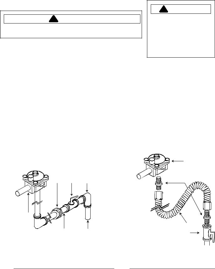
Gas Connection
Connect gas supply to regulator using hard pipe or a flexible connector. Pressure regulator supplied with this appliance has a ½ " NPT female connection.
•A manual shutoff, not supplied with cooktop, must be installed in an accessible location outside of cooktop.
•Use joint compound that is resistant to action of propane gas on all male pipe threads.
•Use supplied pressure regulator only.
•Do not overtighten gas fitting when attaching to pressure regulator. Overtightening may crack regulator.
•Support pressure regulator with wrench when installing gas fitting.
A B C
F
E D
A—Union
B—Manual Shut Off Valve
C—Reducing Elbow (3/4-inch to 1/2-inch) D—3/4-inch Stub
E—1/2-inch Nipple F—Regulator
A—Regulator
B—Adaptor
C—Flexible Connector
D—Manual Shut Off Valve
A
B
 C D
C D
Hardpipe Connection |
Flexible Connection |
9

Installation
Testing for Gas Leaks Place Grates and Burner Caps
! WARNING
To avoid property damage or serious personal injury, never use a lighted match to test for gas leaks.
After final gas connection is made, test all connections in gas supply piping and cooktop for gas leaks.
1.Place soap suds on connection.
•Bubbles appear if leak is present.
To make sure cap is properly aligned and leveled, move burner cap around on burner base. Pegs in the burner base fit into recess in underside of burner cap. Burner cap must be correctly seated on burner base for proper operation of burner.
A
A—Burner grate B—Burner cap C—Burner base
B 
C 
Testing for Gas Leaks
2.Tighten joint if leak is at factory fitting.
•If leak is not at factory fitting, unscrew, apply more joint compound, and tighten to correct leak.
3.Retest connection for leak after tightening.
•Retest any connections that were disturbed.
Make sure proper cap size is on each burner base. Burner does not burn properly if wrong size burner cap is placed on burner base.
Turn on burners to check for proper operation. See Operating Surface Burners section for burner operating instructions.
Correct
Not centered Too small |
Too large |
10
 Loading...