


Amana AMAP151BW, AMAP101BW, AMAP081BW, AMAP061BW, AMAP222BW User Manual
...Room Air Conditioner |
|
Use and Care Guide |
|
Table of Contents |
|
AIR CONDITIONER SAFETY........................................... |
2 |
INSTALLATION REQUIREMENTS.................................. |
3 |
INSTALLATION INSTRUCTIONS— |
|
6,000-12,000 BTU MODELS............................................ |
7 |
WINDOW INSTALLATION INSTRUCTIONS— |
|
15,000-24,000 BTU MODELS........................................ |
10 |
WALL INSTALLATION INSTRUCTIONS— |
|
15,000-24,000 BTU MODELS........................................ |
14 |
For questions about features, operation/performance, |
|
parts, or service, call: 1-800-207-1156. |
|
In Canada, for assistance, installation, or service, |
|
call: 1-800-207-1156. |
|
USING YOUR AIR CONDITIONER............................... |
16 |
AIR CONDITIONER CARE............................................. |
19 |
TROUBLESHOOTING.................................................... |
20 |
ASSISTANCE OR SERVICE.......................................... |
21 |
XLS PRODUCTS WARRANTY FOR |
|
AMANA® AIR CONDITIONERS..................................... |
22 |
Climatiseur |
|
Guide d’utilisation et d’entretien |
|
Table des matières |
|
SÉCURITÉ DU CLIMATISEUR ..................................... |
23 |
EXIGENCES D’INSTALLATION.................................... |
24 |
INSTRUCTIONS D’INSTALLATION— |
|
MODÈLES À 6 000 À 12 000 BTU................................. |
28 |
INSTALLATION DANS UNE FENÊTRE— |
|
MODÈLES À 15 000 À 24 000 BTU............................... |
31 |
INSTRUCTIONS D’INSTALLATION AU MUR— |
|
MODÈLES À 15,000 À 24,000 BTU............................... |
35 |
Au Canada, pour assistance, installation ou service, composez le : 1-800-207-1156.
UTILISATION DE VOTRE CLIMATISEUR.................... |
37 |
ENTRETIEN DU CLIMATISEUR.................................... |
40 |
DÉPANNAGE.................................................................. |
41 |
ASSISTANCE OU SERVICE.......................................... |
42 |
GARANTIE DE XLS PRODUCTS |
|
POUR LES CLIMATISEURS AMANA®.......................... |
43 |
Acondicionador de aire para habitación
Manual de uso y cuidado
Índice
Si tiene preguntas respect o a las características, funcionamiento, rendimiento, partes o servicio técnico, llame al: 1-800-207-1156.
SEGURIDAD DEL ACONDICIONADOR DE AIRE....... |
44 |
REQUISITOS DE INSTALACIÓN.................................. |
45 |
INSTRUCCIONES DE INSTALACIÓN— |
|
MODELOS DE 6,000-12,000 BTU................................. |
49 |
INSTRUCCIONES DE INSTALACIÓN PARA LA |
|
VENTANA— MODELOS DE 15,000-24,000 BTU......... |
52 |
INSTRUCCIONES DE INSTALACIÓN PARA LA |
|
PARED— MODELOS DE 15,000-24,000 BTU.............. |
57 |
USO DE SU ACONDICIONADOR DE AIRE.................. |
59 |
CUIDADO DEL ACONDICIONADOR DE AIRE............ |
63 |
SOLUCIÓN DE PROBLEMAS....................................... |
64 |
AYUDA O SERVICIO TÉCNICO.................................... |
65 |
GARANTÍA DE XLS PRODUCTS PARA |
|
ACONDICIONADORES DE AIRE AMANA®.................. |
66 |
Models/Modèles/Modelos:
AMAP081BW AMAP182BW
AMAP101BW AMAP222BW
AMAP121BW AMAP242BW
AMAP151BW
®/™ ©2017 Amana. All rights reserved. Manufactured under license by XLS Products, Pennsylvania. ®/™ ©2017 Amana. Tous droits réservés. Fabriqué sous licence par XLS Products, Pennsylvanie.
®/™ ©2017 Amana. Todos los derechos reservados. Fabricado bajo licencia por XLS Products, Pennsylvania.
95114
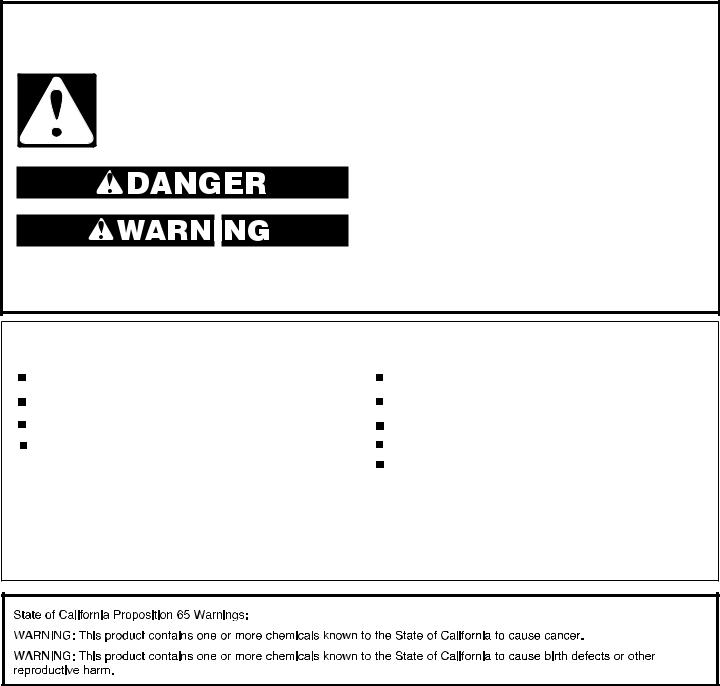
AIR CONDITIONER SAFETY
Your safety and the safety of others are very important.
many important safety messages in this manual and on your appliance. Always read and obey all
.
safety alert symbol.
alerts you to potential hazards that can kill or hurt you and others.
messages will follow the safety alert symbol and either the word “DANGER” or
.” These words mean:
You can be killed or seriously injured if you don't immediately follow instructions.
You can be killed or seriously injured if you don't follow instructions.
All safety messages will tell you what the potential hazard is, tell you how to reduce the chance of injury, and tell you what can happen if the instructions are not followed.
IMPORTANT SAFETY INSTRUCTIONS
WARNING: To reduce the risk of fire, electrical shock or injury when using your air conditioner, follow these basic precautions:
Plug into a grounded 3 prong outlet.
Do not remove ground prong.
Do not use an adapter.
This appliance is not intended for use by persons (including children) with reduced physical, sensory,
or mental capabilities, or lack experience and knowledge, unless they have been given supervision or instruction concerning the use of appliance by a person responsible for their safety.
Do not use an extension cord.
Unplug air conditioner before servicing.
Use two or more people to move and install air conditioner. Do not drink water collected in the water bucket.
Children should be supervised to ensure that they do not play with the appliance.
SAVE THESE INSTRUCTIONS
2

INSTALLATION REQUIREMENTS
Electrical Requirements—All Models
 WARNING
Electrical Shock Hazard Plug into a grounded 3 prong outlet. Do not remove ground prong.
Do not use an adapter.
Do not use an extension cord.
Failure to follow these instructions can result in death, fire, or electrical shock.
The electrical ratings for your air conditioner are listed on the model and serial number label. The model and serial number label is located on the right-hand side of the air conditioner cabinet.
Specific electrical requirements are listed in the “Electrical Requirements” sections. Follow the requirements for the type of plug shown in these sections.
Electrical Requirements—
115 V Models
Model BTUs − 6,000; 8,000; 10,000; 12,000; 15,000
All models −
■■ 115 volts − (103.5 min. - 126.5 max.)
■■ If there is a “Single Circuit Only” label on the unit, use on a dedicated single-outlet circuit only. If a dedicated single-outlet circuit is not available,
then it is the customer’s responsibility to have a single-outlet circuit installed by a qualified electrician.
■■ If there is no “Single Circuit Only” label on the unit, the unit may be used on any branch circuit of correct voltage and adequate current protection rating.
6,000-8,000 BTU models −
■■ 0-8 amps
■■ 10-amp time-delay fuse or circuit breaker
10,000-15,000 BTU models −
■■ 0-12 amps
■■ 15-amp time-delay fuse or circuit breaker
Electrical Requirements—
230 V Models
Model BTUs − 18,000; 22,000; 24,000
■■ 230 volts (208 min. - 240 max.) ■■ 6.6-11 amps
■■ 15-amp time-delay fuse or circuit breaker
■■ If there is a “Single Circuit Only” label on the unit, use on a dedicated single-outlet circuit only.
■■ If a dedicated single-outlet circuit is not available, then it is the customer’s responsibility to have a single-outlet circuit installed by a qualified electrician.
■■ If there is no “Single Circuit Only” label on the unit, the unit may be used on any branch circuit of correct voltage and adequate current protection rating.
Recommended Grounding Method
This air conditioner must be grounded. This air conditioner is equipped with a power supply cord having a grounded 3 prong plug. To minimize possible shock hazard, the cord must be plugged into a mating, grounded 3 prong outlet, grounded in accordance with all local codes and ordinances. If a mating outlet is not available, it is the customer’s responsibility to have a properly grounded 3 prong outlet installed by a qualified electrical installer. It is the customer’s responsibility:
■■ To contact a qualified electrical installer.
■■ To assure that the electrical installation is adequate and in conformance with National Electrical Code, ANSI/NFPA 70— latest edition, and all local codes and ordinances.
Copies of the standards listed may be obtained from:
National Fire Protection Association 1 Batterymarch Park
Quincy, MA 02269
3
Power Supply Cord—All Models
 WARNING
Electrical Shock Hazard Plug into a grounded 3 prong outlet. Do not remove ground prong.
Do not use an adapter.
Do not use an extension cord.
Failure to follow these instructions can result in death, fire, or electrical shock.
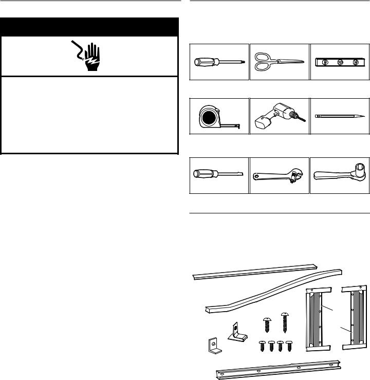
Tools Required—All Models
Gather the required tools and parts before starting installation. Read and follow the instructions provided with any tools listed here.
Phillips screwdriver |
Scissors |
Level |
Tape measure |
Cordless drill and |
Pencil |
|
1/8" bit |
|
NOTE: Your air conditioner’s power supply cord may differ from those shown.
This air conditioner is equipped with a power supply cord required by UL. This power supply cord contains state-of-the-art electronics that sense leakage current. If the cord is crushed, the electronics detect leakage current and power will be disconnected in a fraction of a second.
To test your power supply cord:
1.Plug power supply cord into a grounded 3 prong outlet.
2.Press RESET (on some models, a green light will turn on).
3.Press TEST (listen for click; Reset button will trip, and on some devices, a green light will turn off).
4.Press and release RESET (listen for click; Reset button will latch, and on some devices, a green light will turn on). The power supply cord is ready for operation.
NOTES:
■■ The Reset button must be pushed in for proper operation.
■■ The power supply cord must be replaced if it fails to trip when the test button is pressed or fails to reset.
■■ Do not use the power supply cord as an off/on switch. The power supply cord is designed as a protective device.
■■ A damaged power supply cord must be replaced with a new power supply cord obtained from the product manufacturer and must not be repaired.
■■ The power supply cord contains no user-serviceable parts. Opening the tamper-resistant case voids all warranty and performance claims.
Flathead screwdriver Adjustable wrench Socket wrenches or pliers
Parts Supplied: 6,000-12,000 BTU models
Check that all parts are included in parts package. NOTE: Not all parts are included with all models.
A |
|
|
|
|
|
|
G |
B |
E |
F |
Left |
|
|||
|
|
|
|
D |
|
|
Right |
|
|
H |
|
C |
|
|
|
I |
|
|
|
A. Foam seal with |
|
F. 3/4" screws x4 |
|
adhesive strip |
G. Side curtains x2 |
|
B. Foam seal without |
||
H. 3/8" screws x4 |
||
adhesive strip |
||
I. Top channel (appearance |
||
C. Sash lock x1 |
||
may vary) |
||
D. Lock frame x2 |
||
Other: AAA batteries x2 |
||
E. 1/2" screws x3 |
||
|
4
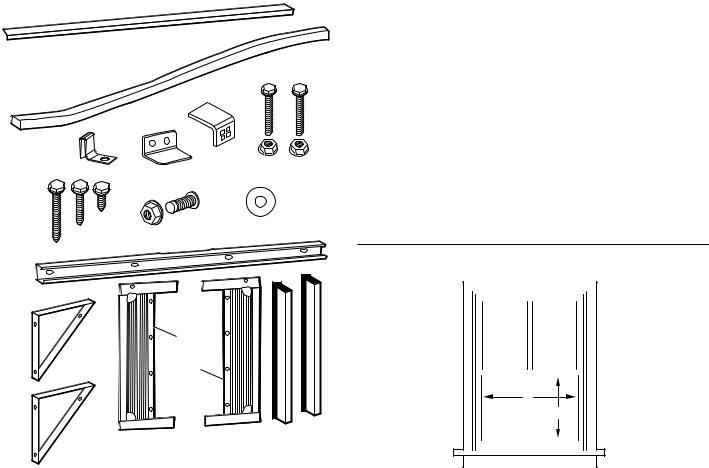
Parts Supplied— |
|
Location Requirements— |
15,000-24,000 BTU Models |
|
Window Installation |
Check that all parts are included in parts package. NOTE: Not all parts are included with all models.
A
IMPORTANT: Observe all governing codes and ordinances.
Check the location where the air conditioner will be installed. Make sure you have everything necessary for correct installation.
The location should provide:
■■ Grounded electrical outlet within 6 ft (183 cm) of where the power cord exits the air conditioner. Do not use an extension cord.
■■ Free movement of air in room to be cooled.
■■ A large enough opening for the air conditioner. Installation parts are supplied for double-hung windows.
B |
|
|
|
|
NOTE: The air conditioner can be installed without the side |
C |
D |
|
E |
|
|
|
|
|
J |
|
panels to fit in a narrow window opening. |
|
|
|
|
■■ |
Adequate wall support for weight of air conditioner. |
|
|
|
|
■■ |
Firm wood, masonry, or metal to secure to supporting parts. |
|
H |
I |
K |
NOTE: Cabinet louvers must not be obstructed. Air must be able |
|
|
G |
|
to pass freely through the cabinet louvers. |
||
|
|
|
|||
F |
|
|
|
|
Window Opening Measurements |
|
|
|
|
|
|
L |
|
|
|
|
|
|
|
Left |
|
|
Right |
M |
|
A |
|
|
|
|
|
B |
|
N |
O |
|
|
A.Foam seal with adhesive strip
B.Foam seal without adhesive strip
C.Side curtain bracket x2
D.Safety lock
E.Sill angle bracket x2
F.1/2" hex-head screw x2
G.5/8" hex-head screw x4
H.5/16" hex-head screw x10
I.5/8" flathead bolt with locknut x2
J.1/2" flathead bolt with locknut x4
K.Gasket x2
L.Top channel (appearance may vary)
M.Window support bracket x2
N.Side curtains x2
O.Side retainers x2
Other: AAA batteries x2
Model BTUs |
Width (A) |
Minimum |
|
|
Opening (B) |
|
|
|
6,000-8,000 |
23"−36" |
141⁄2" |
|
(58.4 cm−91.4 cm) |
(36.8 cm) |
|
|
|
10,000-12,000 |
26"−36" |
16" |
|
(66 cm−91.4 cm) |
(40.6 cm) |
|
|
|
15,000-18,000 |
28"−41" |
19" |
|
(71.1 cm−104.2 cm) |
(48.3 cm) |
|
|
|
22,000-24,000 |
30"−41" |
191⁄2" |
|
(76.2 cm−104.2 cm) |
(49.5 cm) |
|
|
|
5

Prepare Window Opening
1. Measure and mark center line
Width of window opening
 A
A
B Center line
Measure the width of the window opening (A). Mark the center line (B) of the window on the inside windowsill.
2. Attach upper foam seal
Foam seal
Attach the foam seal with adhesive strip to the bottom of the window sash.
Preparing Window with Storm Window or Other Obstruction
Follow the steps in “Prepare Window Opening”.
If possible, remove the storm window frame or other obstruction.
If the storm window frame or obstruction CANNOT be removed, a wood spacer will be required to ensure that the air conditioner slopes to the outside. This will allow condensation and rainwater to drain away. Make sure that drain holes or slots are not caulked or painted shut.
1. Measure size of spacer needed
11/2" (3.8 cm) |
1/2" (1.27 cm) |
||||||||||
Min. |
|||||||||||
Min. |
|
|
|
|
|
|
|
||||
|
|
|
|
|
|
|
|
|
Obstruction |
||
|
|
|
|
|
|
|
|
|
|
||
|
|
|
|
|
|
|
|
|
|
||
Spacer |
|
|
|||||||||
|
|
|
|||||||||
Using a level and measuring tape, determine thickness of wood spacer needed to allow the air conditioner to slope downward slightly to the outdoors. The block should provide at least 1/2" (1.27 cm) of height above the obstruction.
2. Place block on windowsill
|
11/2" (3.8 cm) |
1/2" (1.27 cm) |
|
|
Min. |
||
|
Min. |
||
A. Piece of wood |
|
||
A |
E |
||
B. Windowsill |
|||
|
|||
B |
|
||
C Indoors |
|
||
C |
|
||
D. Outdoors |
|
||
|
D |
||
E. Storm window frame |
|||
|
|||
or other obstruction |
|
|
|
Place wood spacer on windowsill. Spacer should be at least the full width of the air conditioner cabinet.
6

INSTALLATION INSTRUCTIONS—6,000-12,000 BTU MODELS
Prepare Air Conditioner for Installation
 WARNING
Excessive Weight Hazard
Use two or more people to move and install air conditioner.
Failure to do so can result in back or other injury.
1. Unpack the Air Conditioner
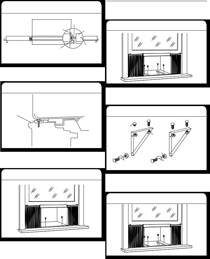
2. Install top channel
Place the top channel on the top of the air conditioner, lining up the holes in the top channel with the holes in the top of the air conditioner.
3. Attach screws
Remove Packaging Materials:
■■ Handle the air conditioner gently while unpacking the unit. ■■ Place the air conditioner on a hard, flat surface.
■■ Remove tape and glue residue from surfaces before turning on the air conditioner. Rub a small amount of liquid dish soap over the adhesive with your fingers. Wipe with a damp cloth and dry.
■■ Do not use sharp instruments, rubbing alcohol, flammable fluids, or abrasive cleaners to remove tape or glue. These products can damage the surface of your air conditioner.
■■ Remove any packaging materials inserted into the side louvers.
■■ Dispose of/recycle packaging materials in an appropriate way.
Using four 3/8" screws, attach the top channel to the air conditioner.
7
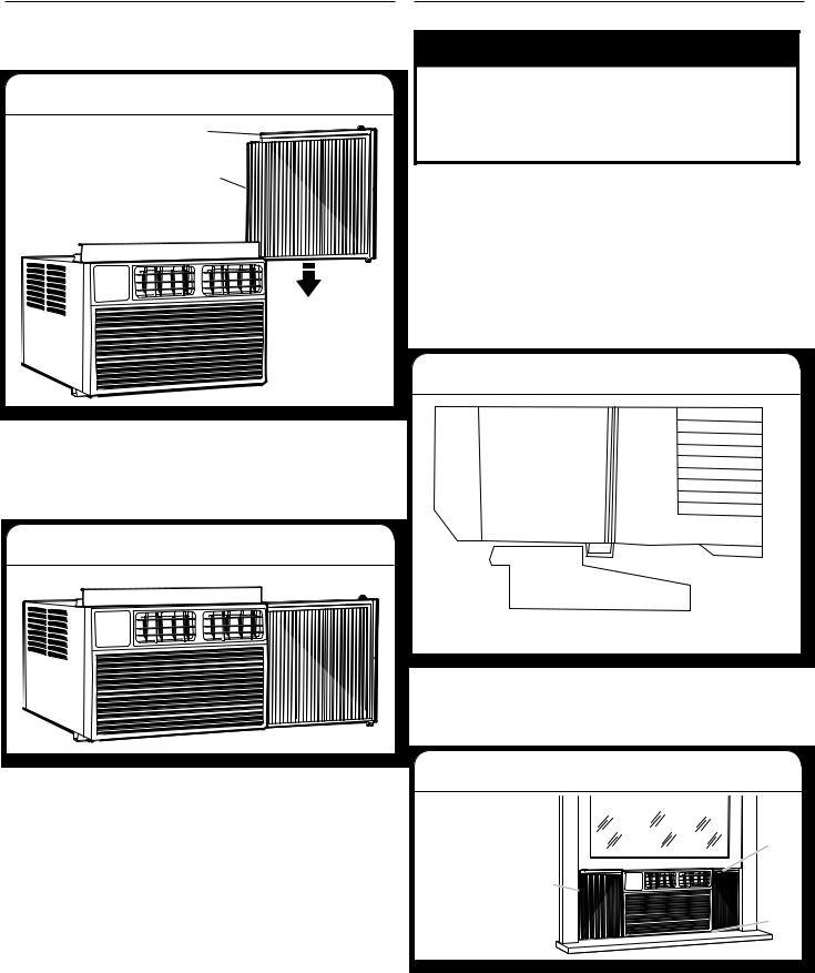
Install Side Curtains
NOTE: Attach curtains to the air conditioner before placing the air conditioner in window.
1. Install side curtain
Right curtain frame
Tabbed side of curtain
Holding the center of the right-hand side panel in one hand, pull the curtain open. Place the tabbed side of the side curtain in the track on the right-hand side of the air conditioner cabinet.
Slide the side curtain down the track, making sure to leave enough space to slip the top and bottom of the frame into the channels on the cabinet.
2. Insert curtain frame into channels
Slide the side curtain frame into the top channel and bottom channels of the air conditioner. Make slight adjustments until the panel sits securely inside the channels.
Repeat steps 1 and 2 for other side curtain and frame.
Install Air Conditioner in Window
 WARNING
Excessive Weight Hazard
Use two or more people to move and install air conditioner.
Failure to do so can result in back or other injury.
IMPORTANT:
■■ Be sure your air conditioner does not fall out of the opening during installation or removal.
■■ The place where the power cord exits the air conditioner should be no more than 6 ft (183 cm) from a grounded outlet
■■ To maximize cooling efficiency and air circulation, do not block the air intake or discharge louvers in the front panel.
■■ To reduce cycling on and off of the compressor and reduce the risk of freezing up or damage to the unit, do not block the louvers on the outside of the air conditioner.
1. Position air conditioner in window
A
 B
B
C
|
|
D |
A. Air conditioner |
C |
Windowsill |
B. Bottom channel |
D. |
Outside |
Using two or more people, place the air conditioner into the window opening so the bottom of the air conditioner frame is against the window sill. Tilt the back of the unit slightly downward to allow accumulated rain water to drain out.
2. Lower window sash into place
A. Side curtain |
|
|
against window |
|
|
channel |
B |
|
B. Window sash |
||
|
||
behind top |
|
|
channel |
A |
|
C. Bottom channel |
||
|
||
behind window |
C |
|
sill |
Lower the window sash behind the top channel to hold the air conditioner in place.
NOTE: Your model may differ from the one shown.
8

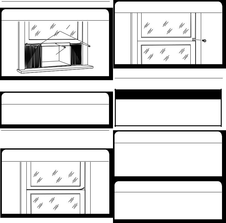
3. Extend side curtains |
|
6. Secure lower sash |
||||||||
|
|
|
|
|
|
|
|
|
|
|
|
|
|
|
|
|
|
|
|
|
|
|
|
|
|
|
|
|
|
|
|
|
|
|
|
|
|
|
|
|
|
|
|
|
|
|
|
|
|
|
|
|
|
|
|
|
|
|
|
|
|
|
|
|
|
|
|
|
|
|
|
|
|
|
|
|
Extend side curtains out until they fit into the window channels.
Attach the right angle sash lock with a 3/4" screw.
4. Install side curtain brackets |
7. Install foam seal |
|
|
A. Top of lower |
|
|
window sash |
A |
|
B. Foam seal |
|
|
|
|
B
Slide a side bracket over the bottom corner of each side curtain frame.
Using a 1/8" drill bit, drill a starter hole through the hole in the side curtain bracket and into the windowsill.
Secure each bracket to the windowsill with a 3/4" screw.
5. Install screws into window sash
Use a 1/8" drill bit to drill a starter hole through the holes in the top rail and the top corners of the side curtains into the window sash.
Secure with three 1/2" screws through the holes in the top rail and side curtain and into the window sash.
Insert the foam seal without adhesive strip between the top of the lower window sash and the glass of the upper window.
Remove any remaining clear plastic film from the control panel and plastic front panel.
9

WINDOW INSTALLATION INSTRUCTIONS— 15,000-24,000 BTU MODELS
Prepare Air Conditioner for Installation
 WARNING
Excessive Weight Hazard
Use two or more people to move and install air conditioner.
Failure to do so can result in back or other injury.
1. Unpack the Air Conditioner
Remove Packaging Materials:
■■ Handle the air conditioner gently while unpacking the unit. ■■ Place the air conditioner on a hard, flat surface.
■■ Remove tape and glue residue from surfaces before turning on the air conditioner. Rub a small amount of liquid dish soap over the adhesive with your fingers. Wipe with a damp cloth and dry.
■■ Do not use sharp instruments, rubbing alcohol, flammable fluids, or abrasive cleaners to remove tape or glue. These products can damage the surface of your air conditioner.
■■ Remove any packaging materials inserted into the side louvers.
■■ Dispose of/recycle packaging materials in an appropriate way.
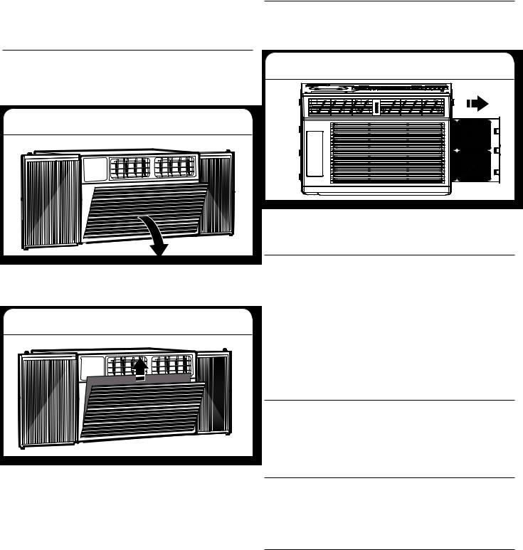
2. Remove filter and front panel
3. Remove faceplate screws
Remove the four faceplate screws.
NOTE: The faceplate screws must be reinstalled before mounting the air conditioner.
4. Remove faceplate
Gently remove the faceplate from the air conditioner cabinet.
5. Remove control panel screw
Remove the control panel screw from the front panel.
Pull down the front panel and remove the filter. Lift the front panel upwards and remove from the air conditioner. Place to the side.
10
6. Remove right-side screws |
3. Slide in side panels |
||||
|
|
|
|
|
|
|
|
|
|
|
|
|
|
|
|
|
|
|
|
|
|
|
|
Remove the screws from the right side of the cabinet.
7. Remove chassis |
Slide the “I” section of the window panel into the side bracket |
|
|
|
f the cabinet. Do this for both sides. |
|
4. Attach side panels |
IMPORTANT: To avoid damage, do not pull or lift near the top of the unit.
Hold the cabinet while pulling on the base handle to carefully remove the unit.
Install Top Channel and Side Bracket
1. Attach foam gasket
Place air conditioner on a hard, flat surface. Attach the foam gasket to the top angle channel.
2. Install top angle channel
Attach the top angle channel to the cabinet with four 5/16" hex-head screws.
5/16" |
screws |
Insert the top and bottom legs of the window filler panel frame into the top angle channel and bottom channel. Secure with 5/16" screws. Repeat on the other side and install side retainer into cabinet.
Install Air Conditioner in Window
 WARNING
Excessive Weight Hazard
Use two or more people to move and install air conditioner.
Failure to do so can result in back or other injury.
IMPORTANT:
■■ Be sure your air conditioner does not fall out of the opening during installation or removal.
■■ The place where the power cord exits the air conditioner should be no more than 6 ft (183 cm) from a grounded outlet.
■■ To maximize cooling efficiency and air circulation, do not block the air intake or discharge louvers in the front panel.
■■ To reduce cycling on and off of the compressor and reduce the risk of freezing up or damage to the unit, do not block the louvers on the outside of the air conditioner.
11
1. Position air conditioner in window
|
B |
|
|
A |
C |
|
|
|
|
D |
E |
|
|
|
A. Air conditioner |
D. “I” section |
|
B. Side panel |
E. Locking screw hole |
|
C. Plastic frame |
|
|
Using two or more people, place the air conditioner into the window opening so the bottom of the air conditioner frame is against the window sill.
2. Close window
Sill
Stool
angle
Install Support Brackets
NOTE: Attach curtains to the air conditioner before placing the air conditioner in window.
1. Mark bracket location
Hold each support bracket flush against the outside of the window sill. Tighten each bracket to the bottom of the cabinet. Mark the location of the brackets at the top level of the windowsill. Remove the brackets.
2. Assemble brackets
1/2" screw 
1/2" locknuts
Make sure the bottom channel is seated over the window sill as shown. Bring the window down temporarily behind the top angle channel to hold the cabinet in place. Tilt the back of the unit slightly downward to allow accumulated rain water to drain out.
3. Secure cabinet
|
5/8" locknuts |
|
5/8" flathead |
Sill angle |
|
bracket |
||
bolt |
||
|
Attach the sill angle brackets to the support brackets with 1/2" screws, flat head bolts, and locknuts as shown. Hand tighten screws loosely to accommodate changes that may be required later in installation.
NOTE: If necessary, pre-drill holes in windowsill.
Fasten the cabinet to the windowsill using two 5/8" round-head screws. Add the bottom channel seal over the screws. For 22,000 and 24,000 BTU models, the bottom channel seal should sit on a gasket.
3. Attach assembled brackets
Attach the support brackets (with sill angle brackets attached) to the bottom of the cabinet with 1/2" screws and locknuts as shown. Tighten all six bolts securely.
12
Extend Side Panels
1. Loosen locking screws
1/2" screws
5/8" |
screw |
Raise the window to expose the window side panel and panel frame. Loosen the locking screws so the side panels slide easily.
2. Extend window panels
Extend each panel to completely fill the width of the window. Tighten the locking screws when the panels are fully extended.
2. Attach right angle safety lock
Attach the right angle safety lock with a 5/8" hex-head screw.
Install the Chassis into the Cabinet
 WARNING
Excessive Weight Hazard
Use two or more people to move and install air conditioner.
Failure to do so can result in back or other injury.
Install Window Lock and Sash Seal
NOTE: Attach curtains to the air conditioner before placing the air conditioner in window.
1. Insert sash seal
Trim the sash seal to fit the width of the window. Insert the sash seal into the space between the upper and lower sashes.
1. Reinsert air conditioner chassis
IMPORTANT: To prevent damage to the unit, do not push on the controls or finned coils.
Using two people, lift the air conditioner chassis and carefully slide it into the cabinet. Let the front of the air conditioner hang out approximately 6" (15.24 cm). Be sure the chassis is firmly seated in the back of the cabinet.
2. Reassemble air conditioner
Insert all screws removed during window installation. Reattach the front faceplate, front panel, and air filter. Refer to the “Prepare Air Conditioner for Installation” section for more information.
13
WALL INSTALLATION INSTRUCTIONS— 15,000-24,000 BTU MODELS
Additional Tools Required
Gather the required tools and parts before starting installation. Read and follow the instructions provided with any tools listed here.
■■ Wood frame ■■ Shims
■■ 10 wood screws − 1" (2.54 cm) long minimum
Selecting a Wall Installation Site
The air conditioner has a slide-out chassis so that it can be installed through an outside wall.
Max wall thickness: 8" (20.32 cm)
IMPORTANT: In order to ensure proper airflow, the side louvers must never be blocked.
Wall requirements:
■■ Allows unblocked airflow from the rear and sides of the air conditioner
■■ Located near existing electrical outlets or where another outlet can or will be installed
■■ Does not support major structural loads, such as the frame construction at ends of windows, under truss-bearing points, etc.
■■ Does not have plumbing or wiring inside
■■ Does not have objects blocking the air vents
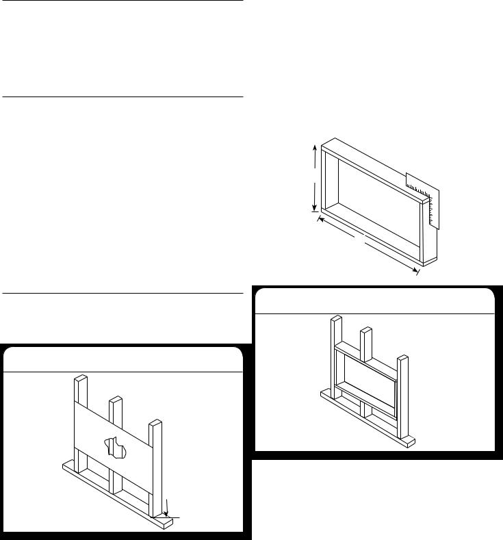
Using the below table to find installation dimensions, measure between the inside edges of every other stud.
Width X=inside model plus twice the thickness of the framing material used.
Height Y= inside model height plus twice the thickness of the framing material used.
|
|
|
15K/18K models |
22K/24K models |
|
|
|
|
|
Inside-frame |
18¼" (46.4 cm) |
191/2" (49.5 cm) |
||
height |
|
|
||
Inside-frame |
237/8" (60.6 cm) |
269/10" (68.3 cm) |
||
width |
|
|
||
|
|
|
|
|
Y
X
Preparing the Wall Installation Site
The air conditioner has a slide-out chassis, so that it can be installed through an outside wall. Prepare the wall in-frame construction (including brick and stucco veneer).
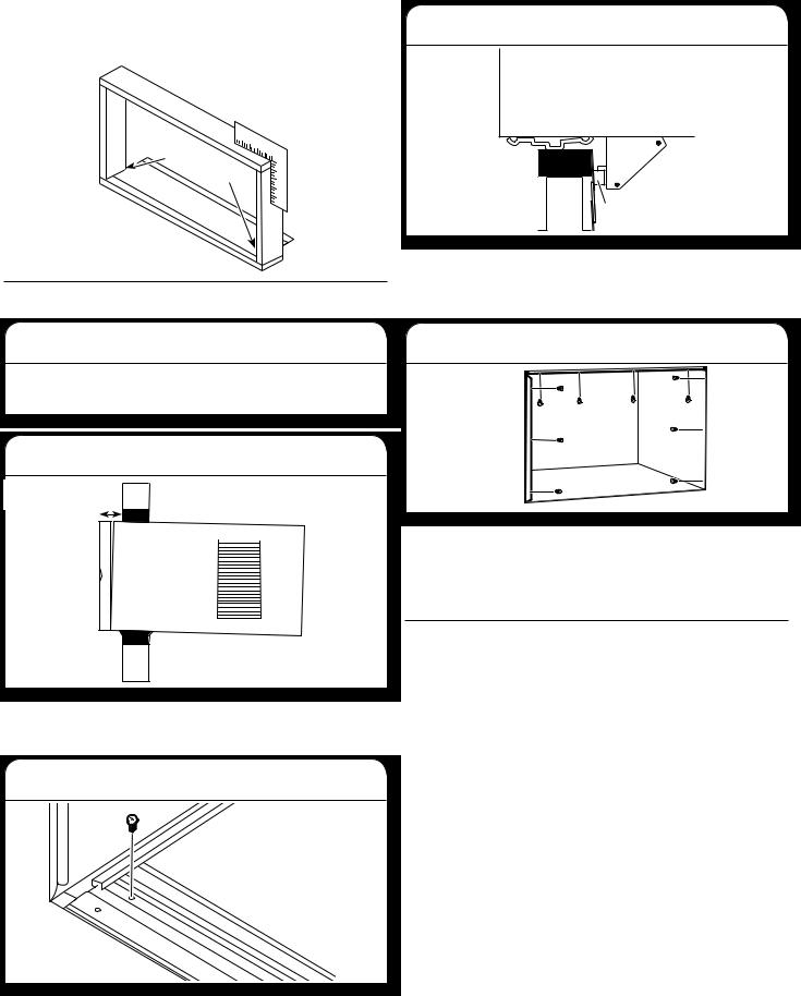
1. Cut a hole on sides of center stud
 33/8" minimum
Working from inside the room, find the wall stud that is nearest to the center of the installation area. Cut a hole on each side of the center stud, leaving at least 33/8" (8.57 cm) below the hole.
2. Build frame
Build a wooden frame with the inside dimensions of your model listed above. The frame depth should be the same as the wall thickness. Fill in extra space from the opening to the studs with wood spacers as shown.
Nail the spacers to the studs. They should be flush with the drywall.
14
NOTE: If the wall thickness is 8½" (21.59 cm) or more, add aluminum flashing over the bottom of the frame opening to assure water is unable to enter the area between the inner and outer wall.
Caulk as
needed
Aluminum 

flashing
Prepare and Install the Cabinet
1. Remove chassis
Slide the chassis from the cabinet. See the “Prepare Air Conditioner for Installation” section for more details.
2. Place and position cabinet
Gap size 5/16" to 3/8"
Place the cabinet into the opening with the bottom channel resting firmly on the bottom rail of the wood frame. Position the cabinet so it is properly tilted for water removal.
3. Secure bottom channel to frame
Secure the bottom channel to the wood frame with two large 1" (2.5 cm) wood screws.
4. Place and position cabinet
 Support
bracket
Wooden
strip
Assemble brackets. See “Install Support Brackets” in the “Window Installation” section. Nail a wooden strip to the outside wall to be used in conjunction with the angled sill support brackets.
5. Secure cabinet and install chassis
Screw or nail the cabinet to the wooden frame using shims if the frame is oversized to eliminate possible noise. Remember to maintain proper slope for water elimination.
Reinstall the chassis into the cabinet. See the “Install the Chassis into the Cabinet” section.
Masonry Construction
1.Cut or build a wall opening in the masonry wall similar to the frame contruction. See the “Wall Installation Instructions – 240 V Models” section for a wall thickness greater than 8½" (21.59 cm).
2.Secure the cabinet in place using masonry nails or masonry anchor screws. Or build a frame using the instructions found in the “Wall Installation Instructions – 240 V Models” section.
3.Make sure the masonry above the cabinet is supported well. Use the existing holes in the cabinet or additional drilled holes to fasten the cabinet at various positions. Make sure that the side louvers are clear of any obstructions.
4.Install the exterior cabinet support brackets according to “Prepare and Install the Cabinet” in the “Wall Installation Instructions – 240 V Models” section. Caulk or flash with aluminum if needed. This will provide a tight seal around the top and sides of the cabinet.
5.For a more aesthetically pleasing installation, apply wood trim molding around the sides of the cabinet without obstructing the side louvers.
15

USING YOUR AIR CONDITIONER
SPEED |
MODE |
Operating your air conditioner properly helps you to obtain the best possible results.
This section explains proper air conditioner operation.
IMPORTANT:
■■ If you turn off the air conditioner, wait at least 3 minutes before turning it back on. This prevents the air conditioner from blowing a fuse or tripping a circuit breaker.
■■ Do not try to operate your air conditioner in the Cool mode when outside temperature is below 65°F (18°C). The inside evaporator coil will freeze up, and the air conditioner will not operate properly.
NOTE: In the event of a power failure, your air conditioner will operate at the previous settings when the power is restored.
Turning on the Air Conditioner
1.Press POWER to turn on air conditioner.
2.Press POWER again to turn off the air conditioner.
Selecting the Mode
1. Press MODE to cycle through modes.
2. Choose Cool, Dry, or Fan.
■■ Cool—Cools the room and reduces air humidity. Press MODE to activate the cooling function. Press the up or down arrow button to adjust the temperature.
■■ |
Dry Mode—Reduces the humidity of the air. |
|
|
Press MODE to set the Dry mode. An automatic |
|
|
function of alternating cooling cycles and air fan is |
|
|
activated. |
|
■■ |
Fan—Only the fan runs. Press MODE to set the |
MODE |
Fan mode. Press FAN SPEED to select High, Med, and Low. The remote control stores the speed set in the previous mode of operation. In Auto mode,
the unit automatically chooses the fan speed and the mode of operation (Cool, Dry, or Fan).
NOTE: After 5 seconds, display will show the current room temperature.
|
Features |
|
|
■■ |
Eco—Conserves energy by turning off |
|
|
|
compressor when room reaches desired |
|
|
|
|
|
|
|
temperature. The fan motor will run for 10 |
|
|
|
minutes, stop for 20 seconds, then run again. |
|
|
|
The compressor will turn back on when the room |
|
|
|
temperature rises above the set temperature. |
|
|
|
Press ECO to turn Eco feature on and off. When |
|
|
|
the unit is in Eco mode, the light will turn on. |
|
|
■■ |
Sleep—Automatically adjusts the temperature |
SPEED |
|
|
and fan speed to make the room more |
|
|
|
comfortable during the night. Press and hold |
|
|
the SLEEP button for 10 seconds until the sleep light turns on. All of the left lights will turn off. The set temperature will automatically raise by 1.8°F (1°C) every 30-60 minutes. At most, the temperature will change six times until the
temperature reaches 82°F (28°C). Running time depends upon the set temperature.
NOTE: After 5 seconds, display will show the current room temperature.
Selecting the Fan Speed
1.Press FAN until the LED indicator for the desired setting is lit.
2.Choose Low, Med, or High. ■■ Low—Low fan speed ■■ Med—Normal fan speed
■■ High—Maximum fan speed
NOTES:
■■ Auto fan speed and temperature cannot be selected in Fan Only mode.
■■ In Eco and Sleep modes, Auto fan speed is selected automatically.
■■ After 5 seconds, the display will show the current room temperature.
Adjusting the Temperature
Press the up arrow button to increase the set temperature.
Press the down arrow button to decrease the set temperature.
NOTE: After 5 seconds, the display on the air conditioner control panel will show the current room temperature.
16

Using the Timer
Delayed Shutoff:
Use the timer to set the air conditioner to turn off automatically after a 0.5- to 24-hour delay (the air conditioner must be on):
1.Press TIMER. The display will show remaining time before the air conditioner will turn off.
2.Press the up or down arrow button to change the delayed shut-off time from 0.5 to 24 hours.
The time can be set in 0.5-hour increments below 10 hours and 1-hour increments for 10 hours or above.
3.Press TIMER again to confirm setting.
NOTE: The Set light will turn on while setting.
Delayed Start:
You can also set the air conditioner to turn on automatically after a 0.5- to 24-hour delay.
NOTE: After the set delay, the air conditioner will turn on with the previous settings. Change the mode, fan speed, and/or temperature before setting the timer, if desired.
1.Turn off the air conditioner.
2.Press TIMER. Set the temperature by pressing the up or down arrow button.
3.Press TIMER a second time to set the rest time. Press the up or down arrow button to change the delay time from 0.5 to 24 hours, then press TIMER again.
4.Press TIMER again while the time remaining is shown on the display.
To Cancel Timer:
After the timer has been set, press TIMER.
Changing Air Direction
Use tab to adjust air direction
Use the thumb wheel on the vent louvers to adjust the air direction left or right.
Normal Operating Sounds
When your air conditioner is operating normally, you may hear sounds such as:
■■ Droplets of water hitting the condenser, causing a pinging or clicking sound. The water droplets help cool the condenser.
■■ Air movement from the fan.
■■ Clicks from the thermostat cycle.
■■ Vibrations or noise due to poor wall or window construction.
■■ A high-pitched hum or pulsating noise caused by the modern high-efficiency compressor cycling on and off.
■■ Water will collect in the base pan during rain or days of high humidity. The water may overflow and drip from the outside part of the unit.
Clean Filter Reminder
To help maximize energy efficiency, this air conditioner features a Clear Filter reminder. After 500 hours of operation, FILTER will illuminate as a reminder that it is time to
clean the filter. Once the light is illuminated, it can be turned off by pressing the FILTER button. See the “Air Conditioner Care” section for instructions on how to clean the filter.
17

Using the Remote Control
POWER COOL
SLEEP |
FAN |
|
SPEED |
TIMER ECO DISPLAY
AUTO |
FAN |
MODE |
ONLY |
Power |
POWER |
1.Press POWER to turn on air conditioner.
2.Press POWER again to turn off the air conditioner.
Cool |
COOL |
|
Press COOL to enter Cool mode.
Fan Speed
1. Press FAN SPEED until you see the bar LED on the air
FAN
conditioner control panel display for the desired setting. SPEED
2. Choose Low, Medium, or High.
NOTES:
■■ Auto fan speed and Temperature cannot be selected in Fan mode.
■■ In Energy Saver (on some models) and Cool modes, Auto fan speed is selected automatically.
Eco
■■ Conserves energy by turning off compressor when
room reaches desired temperature. The fan motor |
ECO |
|
will run for 10 minutes, stop for 20 seconds, then |
||
|
||
run again. The compressor will turn back on when |
|
|
the room temperature rises above the set temperature. Press |
||
ECO to turn Eco feature on and off. When the unit is in Eco |
||
mode, the light will turn on. |
|
|
Adjusting Temperature |
|
|
Press the up arrow button to increase the set |
|
|
temperature. Press the down button to decrease |
|
|
the set temperature. |
ECO |
|
NOTE: After 5 seconds, the display on the air |
||
|
||
conditioner control panel will show the current |
|
|
room temperature. |
|
|
Sleep |
|
|
Automatically adjusts the temperature and fan speed |
|
|
to make the room more comfortable during the night. |
SLEEP |
|
|
||
Press and hold the SLEEP button for 10 seconds until
the Sleep light turns on. All of the left lights will turn off. The set temperature will automatically raise by 1.8°F (1˚C) every 30-60 minutes. At most, the temperature will change six times until the temperature reaches 82°F (28°C). Running time depends upon the set temperature.
Timer
Delayed Shutoff:
Use the timer to set the air conditioner to turn off automatically after a 0.5- to 24-hour delay (the air conditioner must be on):
1. Press TIMER. The display will show remaining time |
|
before the air conditioner will turn off. |
TIMER |
2.Press the up or down arrow button to change the delayed shut-off time from 0.5 to 24 hours. The time
can be set in 0.5-hour increments below 10 hours and 1-hour increments for 10 hours or above.
3.Press TIMER again to confirm setting.
NOTE: The Set light will turn on while setting.
Delayed Start:
You can also set the air conditioner to turn on automatically after a 0.5- to 24-hour delay.
NOTE: After the set delay, the air conditioner will turn on with the previous settings. Change the mode, fan speed, and/or temperature before setting the timer, if desired.
1.Turn off the air conditioner.
2.Press TIMER. Set the temperature by pressing the up or down arrow button.
3.Press TIMER a second time to set the rest time. Press the up or down arrow button to change the delay time from 0.5 to 24 hours, then press TIMER again.
4.Press TIMER again while the time remaining is shown on the display.
To Cancel Timer:
After the timer has been set, press TIMER.
Auto: |
|
||
Press AUTO MODE to enter into Auto mode. In this mode, |
AUTO |
||
the fan speed and temperature are set automatically |
MODE |
||
|
|||
according to the room temperature as tested by the indoor |
|
||
temperature sensor. |
|
||
Display: |
|
|
|
|
|
|
|
Press DISPLAY to switch on/off all lights or the |
LED |
|
DISPLAY |
display. |
|
|
|
Fan only: |
|
|
FAN |
Press the Fan Only button to enter Fan Only mode. |
ONLY |
||
|
|||
Replacing the battery
Remove and replace batteries
Use a small Phillips screwdriver to loosen the battery cover screw. Slide the battery cover down with two thumbs to remove. Remove and properly dispose of old batteries, then replace with two new AAA batteries. Replace the battery cover and tighten the screw.
18
AIR CONDITIONER CARE
Your new air conditioner is designed to give you many years of dependable service. This section tells you how to clean and care for your air conditioner properly.
Air Filter Removal—Top Insert
On some models, the air filter is located behind the intake grille of air conditioner.
1. Removing the intake grille
Turn off the air conditioner.
Remove the air filter by pressing down on the tabs on the air intake grille and pulling the grille away from the air conditioner.
2. Removing the air filter
Remove the filter from the grille by lifting to release the slotted tabs on the top and bottom of the grille.
Reinstalling the air filter:
1.Reattach the air filter to the air intake grille.
2.Insert the air intake grille into the slots on the air conditioner and snap into place.
Air Filter Removal—Side Insert
On some models, the air filter slides out the side of the intake grille.
1. Removing the air filter
Remove the filter by grasping the tab on the filter and pulling it out of the grille to the side.
Reinstalling the air filter:
1. Slide the filter back into the grille.
Cleaning the Air Filter
The air filter is removable for easy cleaning. A clean filter helps remove dust, lint, and other particles from the air and is important for best cooling and operating efficiency. Check the filter at least once per month to see whether it needs cleaning.
NOTE: Do not operate the air conditioner without the filter in place. Doing so will degrade the unit performance over time.
Use a vacuum cleaner to clean air filter. If the air filter is very dirty, wash it in warm water with a mild detergent.
NOTE: Do not wash the air filter in the dishwasher or use any chemical cleaners; it may damage the filter. Air dry the air filter completely before replacing to ensure maximum efficiency.
Cleaning the Front Panel
1.Unplug the air conditioner to prevent shock or a fire hazard.
2.Wipe the front panel with a soft, damp cloth.
3.Air dry the front panel completely.
Repairing Paint Damage
Check once or twice a year for paint damage. This is very important, especially in areas near saltwater or where rust is a problem. If needed, touch up with a good grade enamel paint.
Winter Storage
1.Remove the air conditioner according to the installation instructions.
2.Cover the air conditioner with plastic or place it back into the original box.
19

TROUBLESHOOTING
Before calling for service, try the suggestions below to see whether you can solve your problem without outside help.
 WARNING
Electrical Shock Hazard Plug into a grounded 3 prong outlet. Do not remove ground prong.
Do not use an adapter.
Do not use an extension cord.
Failure to follow these instructions can result in death, fire, or electrical shock.
PROBLEM |
POSSIBLE CAUSES |
RECOMMENDED SOLUTIONS |
|
|
|
The Air Conditioner Will |
The air conditioner is unplugged. |
Make sure the power supply cord is plugged into a |
Not Start |
|
grounded 3 prong outlet. |
|
The fuse is blown/circuit breaker is tripped. |
Check the house fuse/circuit breaker box and replace |
|
|
the fuse or reset the breaker. |
|
|
|
|
Power failure |
The unit will automatically restart when power is |
|
|
restored. There is a protective time delay (approximately |
|
|
3 minutes) to prevent tripping of the compressor |
|
|
overload. The unit may not start normal cooling for |
|
|
3 minutes after it is turned back on. |
|
The power cord reset button is tripped. |
Press the reset button located on the power cord plug. |
|
|
If the reset button will not stay engaged, discontinue |
|
|
use of the air conditioner and contact a qualified service |
|
|
technician. |
|
|
|
The Air Conditioner Is |
Airflow is restricted. |
Make sure there are no curtains, blinds, or furniture |
Not Cooling Properly |
|
blocking the front of the air conditioner. |
|
|
|
|
The temperature control is not set correctly. |
Lower the set thermostat temperature. |
|
|
|
|
The air filter is dirty. |
Clean the filter. See the “Air Conditioner Care” section. |
|
|
|
|
The room is too warm. |
Allow time for the room to cool down after turning on the |
|
|
air conditioner. |
|
|
|
|
Cold air is escaping. |
Close all open doors and/or windows where warm air |
|
|
may be entering. |
|
|
|
|
The cooling coils are frozen. |
See “The Air Conditioner Is Freezing Up” below. |
|
|
|
The Air Conditioner Is |
Ice is blocking the airflow. |
Turn off the unit and allow it to thaw until the ice has |
Freezing Up |
|
melted, then operate on a higher fan speed. If this |
|
|
continues to occur, contact customer service for |
|
|
additional help. |
The Remote Control Is |
Batteries are inserted incorrectly. |
Check that the batteries are inserted in the correct |
Not Working |
|
direction. |
|
Batteries are dead. |
Replace the batteries and dispose of them in a |
|
|
responsible manner. |
20
PROBLEM |
POSSIBLE CAUSES |
RECOMMENDED SOLUTIONS |
|
|
|
Water Is Dripping |
The weather is hot and humid. |
This is normal during periods of high humidity. |
From the Unit on the |
|
NOTE: Do not drill a hole into the bottom of the metal |
Outdoor Side |
|
|
|
base pan; doing so will reduce cooling performance. |
|
|
|
|
|
|
|
Water Is Dripping Inside |
The air conditioner is not properly leveled. |
The air conditioner should slope slightly downward |
the Room |
|
toward the outside. Level the air conditioner to provide |
|
|
a downward slope toward the outside to ensure proper |
|
|
drainage. See the “Installation Instructions” section. |
|
|
NOTE: Do not drill a hole into the bottom of the metal |
|
|
base pan; doing so will reduce cooling performance. |
|
|
|
Water Collects in the |
Moisture removed from the air is collecting |
This is normal. Water that collects in the base pan will |
Base Pan |
in the base pan. |
evaporate to the outside air. This helps with the unit's |
|
|
cooling process. |
|
|
NOTE: Do not drill a hole into the bottom of the metal |
|
|
base pan; doing so will reduce cooling performance. |
|
|
|
ASSISTANCE OR SERVICE
Before calling for assistance or service, please check the “Troubleshooting” section. It may save you the cost of a service call. If you still need help, follow the instructions below.
When calling, please know the purchase date and the complete model and serial numbers of your appliance. This information will help us to better respond to your request.
In the USA
Call XLS Products Customer Service toll free:
1-800-207-1156.
Our consultants provide assistance with:
■■ Features and specifications on our full line of appliances. ■■ Installation information.
■■ Use and maintenance procedures. ■■ Accessory and repair parts.
■■ Specialized customer assistance.
■■ Referrals to local dealers, repair parts distributors, and service companies. XLS Products-designated service technicians
are trained to fulfill the product warranty and provide afterwarranty service, anywhere in the United States.
For further assistance:
If you need further assistance, you can write to XLS Products with any questions or concerns at:
XLS Products, Inc.
Customer Service
P.O. Box 16262 Philadelphia, PA 19114-0262
Please include a daytime phone number in your correspondence.
In Canada
Call XLS Products Customer Service toll free:
1-800-207-1156.
Our consultants provide assistance with:
■■ Features and specifications on our full line of appliances. ■■ Use and maintenance procedures.
■■ Accessory and repair parts.
■■ Referrals to local dealers, repair parts distributors, and service companies. XLS Products-designated service technicians
are trained to fulfill the product warranty and provide afterwarranty service, anywhere in Canada.
For further assistance:
If you need further assistance, you can write to XLS Products with any questions or concerns at:
XLS Products, Inc.
Customer Service
P.O. Box 16262 Philadelphia, PA 19114-0262
Please include a daytime phone number in your correspondence.
21
 Loading...