

Page 1

CentricStor V3.1D
User Guide
Edition July 2007
Page 2

Comments… Suggestions… Corrections…
The User Documentation Department would like to know your
opinion on this manual. Your feedback helps us to optimize our
documentation to suit your individual needs.
Feel free to send us your comments by e-mail to:
manuals@fujitsu-siemens.com
Certified documentation
according to DIN EN ISO 9001:2000
To ensure a consistently high quality standard and
user-friendliness, this documentation was created to
meet the regulations of a quality management system which
complies with the requirements of the standard
DIN EN ISO 9001:2000.
cognitas. Gesellschaft für Technik-Dokumentation mbH
www.cognitas.de
Copyright and Trademarks
Copyright © Fujitsu Siemens Computers GmbH 2007.
All rights reserved.
Delivery subject to availability; right of technical modifications reserved.
All hardware and software names used are trademarks of their respective manufacturers.
This manual was produced by
cognitas. Gesellschaft für Technik-Dokumentation mbH
www.cognitas.de
This manual is printed
on paper treated with
chlorine-free bleach.
Page 3

Contents
1 Introduction . . . . . . . . . . . . . . . . . . . . . . . . . . . . . . . . . . . . . . .19
1.1 Objective and target group for the manual . . . . . . . . . . . . . . . . . . . . . . 20
1.2 Concept of the manual . . . . . . . . . . . . . . . . . . . . . . . . . . . . . . . . . 20
1.3 Notational conventions . . . . . . . . . . . . . . . . . . . . . . . . . . . . . . . . 21
1.4 Note . . . . . . . . . . . . . . . . . . . . . . . . . . . . . . . . . . . . . . . . . . . 21
2 CentricStor - Virtual Tape Library . . . . . . . . . . . . . . . . . . . . . . . . . . . 23
2.1 The CentricStor principle . . . . . . . . . . . . . . . . . . . . . . . . . . . . . . . 23
2.2 Hardware architecture . . . . . . . . . . . . . . . . . . . . . . . . . . . . . . . . . 26
2.2.1 ISP (Integrated Service Processor) . . . . . . . . . . . . . . . . . . . . . . . . . . . 27
2.2.1.1 VLP (Virtual Library Processor) . . . . . . . . . . . . . . . . . . . . . . . . . . . 27
2.2.1.2 ICP (Integrated Channel Processor) . . . . . . . . . . . . . . . . . . . . . . . . . 28
2.2.1.3 IDP (Integrated Device Processor) . . . . . . . . . . . . . . . . . . . . . . . . . 29
2.2.1.4 ICP_IDP or IUP (Integrated Universal Processor) . . . . . . . . . . . . . . . . . . 29
2.2.2 RAID systems for the Tape Volume Cache . . . . . . . . . . . . . . . . . . . . . . . 30
2.2.3 FibreChannel (FC) . . . . . . . . . . . . . . . . . . . . . . . . . . . . . . . . . . . .31
2.2.4 FC switch (fibre channel switch) . . . . . . . . . . . . . . . . . . . . . . . . . . . . . 31
2.2.5 Host connection . . . . . . . . . . . . . . . . . . . . . . . . . . . . . . . . . . . . .32
2.3 Software architecture . . . . . . . . . . . . . . . . . . . . . . . . . . . . . . . . . 32
2.4 Operation . . . . . . . . . . . . . . . . . . . . . . . . . . . . . . . . . . . . . . . . 35
2.5 Administering the tape cartridges . . . . . . . . . . . . . . . . . . . . . . . . . . 35
2.5.1 Writing the tape cartridges according to the stacked volume principle . . . . . . . . . 35
2.5.2 Repeated writing of a logical volume onto tape . . . . . . . . . . . . . . . . . . . . . 36
2.5.3 Creating a directory . . . . . . . . . . . . . . . . . . . . . . . . . . . . . . . . . . .36
2.5.4 Reorganization of the tape cartridges . . . . . . . . . . . . . . . . . . . . . . . . . . 37
U41117-J-Z125-7-76
Page 4

Contents
2.6 Procedures . . . . . . . . . . . . . . . . . . . . . . . . . . . . . . . . . . . . . . .38
2.6.1 Creating the CentricStor data maintenance . . . . . . . . . . . . . . . . . . . . . . . 38
2.6.2 Issuing a mount job from the host . . . . . . . . . . . . . . . . . . . . . . . . . . . . 39
2.6.3 Scratch mount . . . . . . . . . . . . . . . . . . . . . . . . . . . . . . . . . . . . . . 42
2.7 New system functions . . . . . . . . . . . . . . . . . . . . . . . . . . . . . . . . . 43
2.8 Standard system functions . . . . . . . . . . . . . . . . . . . . . . . . . . . . . . 44
2.8.1 Partitioning by volume groups . . . . . . . . . . . . . . . . . . . . . . . . . . . . . . 44
2.8.2 “Call Home” in the event of an error . . . . . . . . . . . . . . . . . . . . . . . . . . . 44
2.8.3 SNMP support . . . . . . . . . . . . . . . . . . . . . . . . . . . . . . . . . . . . . .45
2.8.4 Exporting and importing tape cartridges . . . . . . . . . . . . . . . . . . . . . . . . . 45
2.8.4.1 Vault attribute and vault status . . . . . . . . . . . . . . . . . . . . . . . . . . . . 46
2.8.4.2 Transfer PVG . . . . . . . . . . . . . . . . . . . . . . . . . . . . . . . . . . . . .46
2.9 Optional system functions . . . . . . . . . . . . . . . . . . . . . . . . . . . . . . . 47
2.9.1 Compression . . . . . . . . . . . . . . . . . . . . . . . . . . . . . . . . . . . . . . . 48
2.9.2 Multiple library support . . . . . . . . . . . . . . . . . . . . . . . . . . . . . . . . . .49
2.9.3 Dual Save . . . . . . . . . . . . . . . . . . . . . . . . . . . . . . . . . . . . . . . . 50
2.9.4 Extending virtual drives . . . . . . . . . . . . . . . . . . . . . . . . . . . . . . . . .52
2.9.5 System administrator’s edition . . . . . . . . . . . . . . . . . . . . . . . . . . . . . . 52
2.9.6 Fibre channel connection for load balancing and redundancy . . . . . . . . . . . . . . 52
2.9.7 Automatic VLP failover . . . . . . . . . . . . . . . . . . . . . . . . . . . . . . . . . . 52
2.9.8 Cache Mirroring Feature . . . . . . . . . . . . . . . . . . . . . . . . . . . . . . . . . 55
2.9.8.1 General . . . . . . . . . . . . . . . . . . . . . . . . . . . . . . . . . . . . . . . 55
2.9.8.2 Hardware requirements . . . . . . . . . . . . . . . . . . . . . . . . . . . . . . . 55
2.9.8.3 Software requirements . . . . . . . . . . . . . . . . . . . . . . . . . . . . . . . . 56
2.9.8.4 Mirrored RAID systems . . . . . . . . . . . . . . . . . . . . . . . . . . . . . . . 57
2.9.8.5 Presentation of the mirror function in GXCC . . . . . . . . . . . . . . . . . . . . 58
2.9.9 Accounting . . . . . . . . . . . . . . . . . . . . . . . . . . . . . . . . . . . . . . . . 59
3 Switching CentricStor on/off . . . . . . . . . . . . . . . . . . . . . . . . . . . . . 61
3.1 Switching CentricStor on . . . . . . . . . . . . . . . . . . . . . . . . . . . . . . . 61
3.2 Switching CentricStor off . . . . . . . . . . . . . . . . . . . . . . . . . . . . . . . 62
4 Selected system administrator activities . . . . . . . . . . . . . . . . . . . . . . . 63
4.1 Partitioning on the basis of volume groups . . . . . . . . . . . . . . . . . . . . . 63
4.1.1 General . . . . . . . . . . . . . . . . . . . . . . . . . . . . . . . . . . . . . . . . . 63
4.1.2 Rules . . . . . . . . . . . . . . . . . . . . . . . . . . . . . . . . . . . . . . . . . . . 64
U41117-J-Z125-7-76
Page 5

Contents
4.1.3 System administrator activities . . . . . . . . . . . . . . . . . . . . . . . . . . . . . 65
4.1.3.1 Adding a logical volume group . . . . . . . . . . . . . . . . . . . . . . . . . . . . 66
4.1.3.2 Adding a physical volume group . . . . . . . . . . . . . . . . . . . . . . . . . . . 66
4.1.3.3 Adding logical volumes to a logical volume group . . . . . . . . . . . . . . . . . . 66
4.1.3.4 Adding physical volumes to a physical volume group . . . . . . . . . . . . . . . . 67
4.1.3.5 Assigning an LVG to a PVG . . . . . . . . . . . . . . . . . . . . . . . . . . . . . 67
4.1.3.6 Removing an assignment between an LVG and a PVG . . . . . . . . . . . . . . . 67
4.1.3.7 Changing logical volumes to another group . . . . . . . . . . . . . . . . . . . . . 68
4.1.3.8 Removing logical volumes . . . . . . . . . . . . . . . . . . . . . . . . . . . . . . 68
4.1.3.9 Removing logical volume groups . . . . . . . . . . . . . . . . . . . . . . . . . . 68
4.1.3.10 Removing physical volumes from a physical volume group . . . . . . . . . . . . . 69
4.1.3.11 Removing physical volume groups . . . . . . . . . . . . . . . . . . . . . . . . . 69
4.2 Cache management . . . . . . . . . . . . . . . . . . . . . . . . . . . . . . . . . . 70
4.3 Dual Save . . . . . . . . . . . . . . . . . . . . . . . . . . . . . . . . . . . . . . . . 71
4.3.1 General . . . . . . . . . . . . . . . . . . . . . . . . . . . . . . . . . . . . . . . . . 71
4.3.2 System administrator activities . . . . . . . . . . . . . . . . . . . . . . . . . . . . . 72
4.3.2.1 Assigning a logical volume group to two physical volume groups . . . . . . . . . . 72
4.3.2.2 Removing a Dual Save assignment . . . . . . . . . . . . . . . . . . . . . . . . . 72
4.4 Reorganization . . . . . . . . . . . . . . . . . . . . . . . . . . . . . . . . . . . . . 73
4.4.1 Why do we need reorganization? . . . . . . . . . . . . . . . . . . . . . . . . . . . . 73
4.4.2 How is a physical volume reorganized? . . . . . . . . . . . . . . . . . . . . . . . . . 74
4.4.3 When is a reorganization performed? . . . . . . . . . . . . . . . . . . . . . . . . . . 75
4.4.4 Which physical volume is selected for reorganization? . . . . . . . . . . . . . . . . . 76
4.4.5 Own physical volumes for reorganization backup . . . . . . . . . . . . . . . . . . . . 78
4.4.6 Starting the reorganization of a physical volume . . . . . . . . . . . . . . . . . . . . 78
4.4.7 Configuration parameters . . . . . . . . . . . . . . . . . . . . . . . . . . . . . . . . 79
4.5 Cleaning physical drives . . . . . . . . . . . . . . . . . . . . . . . . . . . . . . . . 81
4.6 Synchronization of the system time using NTP . . . . . . . . . . . . . . . . . . . 82
5 Operating and monitoring CentricStor . . . . . . . . . . . . . . . . . . . . . . . . 83
5.1 Technical design . . . . . . . . . . . . . . . . . . . . . . . . . . . . . . . . . . . . 83
5.1.1 General . . . . . . . . . . . . . . . . . . . . . . . . . . . . . . . . . . . . . . . . . 83
5.1.2 Principles of operation of GXCC . . . . . . . . . . . . . . . . . . . . . . . . . . . . . 84
5.1.3 Monitoring structure within a CentricStor ISP . . . . . . . . . . . . . . . . . . . . . . 87
5.1.4 Operating modes . . . . . . . . . . . . . . . . . . . . . . . . . . . . . . . . . . . .90
5.2 Operator configuration . . . . . . . . . . . . . . . . . . . . . . . . . . . . . . . . . 91
5.2.1 Basic configuration . . . . . . . . . . . . . . . . . . . . . . . . . . . . . . . . . . . .91
5.2.2 Expansion . . . . . . . . . . . . . . . . . . . . . . . . . . . . . . . . . . . . . . . . 91
U41117-J-Z125-7-76
Page 6

Contents
5.2.3 GXCC in other systems . . . . . . . . . . . . . . . . . . . . . . . . . . . . . . . . . 92
5.2.4 Screen display requirements . . . . . . . . . . . . . . . . . . . . . . . . . . . . . . 92
5.2.5 Managing CentricStor via SNMP . . . . . . . . . . . . . . . . . . . . . . . . . . . . 92
5.2.5.1 Connection to SNMP management systems . . . . . . . . . . . . . . . . . . . . 92
5.2.5.2 SNMP and GXCC . . . . . . . . . . . . . . . . . . . . . . . . . . . . . . . . . . 93
5.3 Starting GXCC . . . . . . . . . . . . . . . . . . . . . . . . . . . . . . . . . . . . . 95
5.3.1 Differences to earlier CentricStor versions . . . . . . . . . . . . . . . . . . . . . . . 95
5.3.2 Command line . . . . . . . . . . . . . . . . . . . . . . . . . . . . . . . . . . . . . .95
5.3.2.1 Explanation of the start parameter -aspect . . . . . . . . . . . . . . . . . . . . . 97
5.3.3 Environment variable XTCC_CLASS . . . . . . . . . . . . . . . . . . . . . . . . . . 98
5.3.4 Passwords . . . . . . . . . . . . . . . . . . . . . . . . . . . . . . . . . . . . . . . . 98
5.3.4.1 Optional access control for Observe mode . . . . . . . . . . . . . . . . . . . . . 99
5.3.4.2 Authentication . . . . . . . . . . . . . . . . . . . . . . . . . . . . . . . . . . . .99
5.3.4.3 Suppressing the password query . . . . . . . . . . . . . . . . . . . . . . . . . 100
5.3.4.4 Additional password query . . . . . . . . . . . . . . . . . . . . . . . . . . . . . 101
5.3.5 Starting the CentricStor console . . . . . . . . . . . . . . . . . . . . . . . . . . . . 102
5.3.6 Starting from an X11 server . . . . . . . . . . . . . . . . . . . . . . . . . . . . . . 102
5.3.6.1 General notes on the X11 server architecture . . . . . . . . . . . . . . . . . . . 102
5.3.6.2 Using the direct XDMCP interface . . . . . . . . . . . . . . . . . . . . . . . . . 104
5.3.6.3 Starting from a UNIX system . . . . . . . . . . . . . . . . . . . . . . . . . . . 104
5.3.6.4 Starting from a Windows system via Exceed . . . . . . . . . . . . . . . . . . . 105
5.3.6.5 Starting from a Windows/NT system via XVision . . . . . . . . . . . . . . . . . 108
5.3.7 GXCC welcome screen . . . . . . . . . . . . . . . . . . . . . . . . . . . . . . . . 114
5.3.8 Selecting the CentricStor system . . . . . . . . . . . . . . . . . . . . . . . . . . . 116
5.3.9 Establishing a connection after clicking on OK . . . . . . . . . . . . . . . . . . . . 116
5.3.10 Authentication . . . . . . . . . . . . . . . . . . . . . . . . . . . . . . . . . . . . . 117
5.3.11 Software updates . . . . . . . . . . . . . . . . . . . . . . . . . . . . . . . . . . . 118
6 GXCC . . . . . . . . . . . . . . . . . . . . . . . . . . . . . . . . . . . . . . . . . 119
6.1 Main window . . . . . . . . . . . . . . . . . . . . . . . . . . . . . . . . . . . . . 119
6.1.1 Standard . . . . . . . . . . . . . . . . . . . . . . . . . . . . . . . . . . . . . . . . 119
6.1.2 Loss of a connection . . . . . . . . . . . . . . . . . . . . . . . . . . . . . . . . . . 120
6.1.3 Elements of the GXCC main window . . . . . . . . . . . . . . . . . . . . . . . . . 121
6.1.3.1 Title bar . . . . . . . . . . . . . . . . . . . . . . . . . . . . . . . . . . . . . . 121
6.1.3.2 Footer . . . . . . . . . . . . . . . . . . . . . . . . . . . . . . . . . . . . . . . 121
6.1.3.3 Function buttons and displays in the button bar . . . . . . . . . . . . . . . . . . 123
6.1.3.4 System information . . . . . . . . . . . . . . . . . . . . . . . . . . . . . . . . 123
6.1.3.5 Console messages . . . . . . . . . . . . . . . . . . . . . . . . . . . . . . . . 124
6.1.3.6 Function bar . . . . . . . . . . . . . . . . . . . . . . . . . . . . . . . . . . . . 124
6.1.4 Message window . . . . . . . . . . . . . . . . . . . . . . . . . . . . . . . . . . . 125
6.1.5 Asynchronous errors . . . . . . . . . . . . . . . . . . . . . . . . . . . . . . . . . . 125
U41117-J-Z125-7-76
Page 7

Contents
6.1.6 Block diagram . . . . . . . . . . . . . . . . . . . . . . . . . . . . . . . . . . . . . 126
6.1.6.1 Status information . . . . . . . . . . . . . . . . . . . . . . . . . . . . . . . . . 133
6.1.6.2 Object information and object-related functions . . . . . . . . . . . . . . . . . . 133
6.1.7 ICP object information . . . . . . . . . . . . . . . . . . . . . . . . . . . . . . . . . 134
6.1.8 IDP object information . . . . . . . . . . . . . . . . . . . . . . . . . . . . . . . . . 135
6.1.9 Functions of an ISP . . . . . . . . . . . . . . . . . . . . . . . . . . . . . . . . . . 135
6.1.9.1 Show Details (XTCC) . . . . . . . . . . . . . . . . . . . . . . . . . . . . . . . 135
6.1.10 Functions for all ISPs of a particular class . . . . . . . . . . . . . . . . . . . . . . . 135
6.1.11 Information about the RAID systems . . . . . . . . . . . . . . . . . . . . . . . . . 136
6.1.12 RAID system functions . . . . . . . . . . . . . . . . . . . . . . . . . . . . . . . . . 137
6.1.12.1 Show complete RAID status . . . . . . . . . . . . . . . . . . . . . . . . . . . . 137
6.1.13 Information on Fibre Channel fabric . . . . . . . . . . . . . . . . . . . . . . . . . . 138
6.1.14 Functions of the Fibre Channel fabric . . . . . . . . . . . . . . . . . . . . . . . . . 138
6.1.14.1 Controller Color Scheme . . . . . . . . . . . . . . . . . . . . . . . . . . . . . 139
6.1.14.2 Show data fcswitch <Name of the switch> [(trap)] . . . . . . . . . . . . . . . . . 139
6.1.15 Information about the FC connections . . . . . . . . . . . . . . . . . . . . . . . . . 140
6.1.16 Information on the archive systems . . . . . . . . . . . . . . . . . . . . . . . . . . 140
6.1.17 ISP system messages . . . . . . . . . . . . . . . . . . . . . . . . . . . . . . . . . 141
6.1.18 SNMP messages . . . . . . . . . . . . . . . . . . . . . . . . . . . . . . . . . . . 141
6.1.19 Configuration Changed . . . . . . . . . . . . . . . . . . . . . . . . . . . . . . . . 142
6.2 Function bar . . . . . . . . . . . . . . . . . . . . . . . . . . . . . . . . . . . . . 143
6.2.1 Overview of GXCC functions . . . . . . . . . . . . . . . . . . . . . . . . . . . . . 143
6.2.2 File . . . . . . . . . . . . . . . . . . . . . . . . . . . . . . . . . . . . . . . . . . . 145
6.2.2.1 Save . . . . . . . . . . . . . . . . . . . . . . . . . . . . . . . . . . . . . . . . 145
6.2.2.2 Open . . . . . . . . . . . . . . . . . . . . . . . . . . . . . . . . . . . . . . . . 146
6.2.2.3 Show . . . . . . . . . . . . . . . . . . . . . . . . . . . . . . . . . . . . . . . . 146
6.2.2.4 Print . . . . . . . . . . . . . . . . . . . . . . . . . . . . . . . . . . . . . . . . 146
6.2.2.5 Exit . . . . . . . . . . . . . . . . . . . . . . . . . . . . . . . . . . . . . . . . . 147
6.2.3 Unit . . . . . . . . . . . . . . . . . . . . . . . . . . . . . . . . . . . . . . . . . . . 147
6.2.3.1 Select . . . . . . . . . . . . . . . . . . . . . . . . . . . . . . . . . . . . . . . 147
6.2.4 Options . . . . . . . . . . . . . . . . . . . . . . . . . . . . . . . . . . . . . . . . . 150
6.2.4.1 Settings . . . . . . . . . . . . . . . . . . . . . . . . . . . . . . . . . . . . . . 150
6.2.4.2 Show Current Aspect . . . . . . . . . . . . . . . . . . . . . . . . . . . . . . . 151
6.2.5 Autoscan . . . . . . . . . . . . . . . . . . . . . . . . . . . . . . . . . . . . . . . . 152
6.2.5.1 Start Autoscan/Stop Autoscan . . . . . . . . . . . . . . . . . . . . . . . . . . . 152
6.2.5.2 Settings . . . . . . . . . . . . . . . . . . . . . . . . . . . . . . . . . . . . . . 153
6.2.6 Tools . . . . . . . . . . . . . . . . . . . . . . . . . . . . . . . . . . . . . . . . . . 154
6.2.6.1 Global Status . . . . . . . . . . . . . . . . . . . . . . . . . . . . . . . . . . . 154
6.2.6.2 Get Remote/Expand Local File . . . . . . . . . . . . . . . . . . . . . . . . . . 154
6.2.6.3 Show Remote File . . . . . . . . . . . . . . . . . . . . . . . . . . . . . . . . . 156
6.2.6.4 Show System Messages . . . . . . . . . . . . . . . . . . . . . . . . . . . . . 158
6.2.6.5 GXCC Update/Revert Tool . . . . . . . . . . . . . . . . . . . . . . . . . . . . . 159
U41117-J-Z125-7-76
Page 8

Contents
6.2.7 Configuration . . . . . . . . . . . . . . . . . . . . . . . . . . . . . . . . . . . . . . 166
6.2.7.1 RAID Filesystems . . . . . . . . . . . . . . . . . . . . . . . . . . . . . . . . . 171
6.2.7.2 Logical Volume Groups . . . . . . . . . . . . . . . . . . . . . . . . . . . . . . 173
6.2.7.3 Physical Volume Groups . . . . . . . . . . . . . . . . . . . . . . . . . . . . . . 181
6.2.7.4 Distribute and Activate . . . . . . . . . . . . . . . . . . . . . . . . . . . . . . . 188
6.2.8 Profile . . . . . . . . . . . . . . . . . . . . . . . . . . . . . . . . . . . . . . . . . 191
6.2.8.1 Add/Select Profile . . . . . . . . . . . . . . . . . . . . . . . . . . . . . . . . . 191
6.2.9 Administration . . . . . . . . . . . . . . . . . . . . . . . . . . . . . . . . . . . . . 193
6.2.9.1 Show WWN’s . . . . . . . . . . . . . . . . . . . . . . . . . . . . . . . . . . . 195
6.2.9.2 Show Optional Functions . . . . . . . . . . . . . . . . . . . . . . . . . . . . . 196
6.2.9.3 Show CS Configuration . . . . . . . . . . . . . . . . . . . . . . . . . . . . . . 197
6.2.9.4 Diagnostic Snapshots . . . . . . . . . . . . . . . . . . . . . . . . . . . . . . . 197
6.2.9.5 Logical Volume Operations . . . . . . . . . . . . . . . . . . . . . . . . . . . . 202
6.2.9.6 Logical Volume Operations » Show Logical Volumes . . . . . . . . . . . . . . . 203
6.2.9.7 Logical Volume Operations » Show Logical Volumes (physical view) . . . . . . . 207
6.2.9.8 Logical Volume Operations » Change Volume Group . . . . . . . . . . . . . . . 209
6.2.9.9 Logical Volume Operations » Add Logical Volumes . . . . . . . . . . . . . . . . 211
6.2.9.10 Logical Volume Operations » Erase Logical Volumes . . . . . . . . . . . . . . . 213
6.2.9.11 Physical Volume Operations . . . . . . . . . . . . . . . . . . . . . . . . . . . . 215
6.2.9.12 Physical Volume Operations » Show Physical Volumes . . . . . . . . . . . . . . 215
6.2.9.13 Physical Volume Operations » Link/Unlink Volume Groups . . . . . . . . . . . . 221
6.2.9.14 Physical Volume Operations » Add Physical Volumes . . . . . . . . . . . . . . . 223
6.2.9.15 Physical Volume Operations » Erase Physical Volumes . . . . . . . . . . . . . . 226
6.2.9.16 Physical Volume Operations » Reorganize Physical Volumes . . . . . . . . . . . 228
6.2.9.17 Setup for accounting mails . . . . . . . . . . . . . . . . . . . . . . . . . . . . . 229
6.2.10 Help . . . . . . . . . . . . . . . . . . . . . . . . . . . . . . . . . . . . . . . . . . 232
6.2.10.1 Readme / LIESMICH . . . . . . . . . . . . . . . . . . . . . . . . . . . . . . . 232
6.2.10.2 Direct Help / Direkthilfe . . . . . . . . . . . . . . . . . . . . . . . . . . . . . . 232
6.2.10.3 System Messages . . . . . . . . . . . . . . . . . . . . . . . . . . . . . . . . . 232
6.2.10.4 About GXCC... . . . . . . . . . . . . . . . . . . . . . . . . . . . . . . . . . . . 232
6.2.10.5 Revision Summary . . . . . . . . . . . . . . . . . . . . . . . . . . . . . . . . . 233
6.2.10.6 Hardware Summary . . . . . . . . . . . . . . . . . . . . . . . . . . . . . . . . 234
6.2.10.7 Online Manual . . . . . . . . . . . . . . . . . . . . . . . . . . . . . . . . . . . 235
7 Global Status . . . . . . . . . . . . . . . . . . . . . . . . . . . . . . . . . . . . . 237
7.1 General . . . . . . . . . . . . . . . . . . . . . . . . . . . . . . . . . . . . . . . . 237
7.2 Operation of the Global Status Monitor . . . . . . . . . . . . . . . . . . . . . . . 239
7.3 Function bar of the Global Status Monitor . . . . . . . . . . . . . . . . . . . . . 239
7.3.1 File . . . . . . . . . . . . . . . . . . . . . . . . . . . . . . . . . . . . . . . . . . . 239
7.3.1.1 Print . . . . . . . . . . . . . . . . . . . . . . . . . . . . . . . . . . . . . . . . 239
U41117-J-Z125-7-76
Page 9

Contents
7.3.1.2 Exit . . . . . . . . . . . . . . . . . . . . . . . . . . . . . . . . . . . . . . . . . 240
7.3.2 Config . . . . . . . . . . . . . . . . . . . . . . . . . . . . . . . . . . . . . . . . . 241
7.3.3 Tools . . . . . . . . . . . . . . . . . . . . . . . . . . . . . . . . . . . . . . . . . . 242
7.3.3.1 Global eXtended Control Center . . . . . . . . . . . . . . . . . . . . . . . . . . 242
7.3.3.2 Show Balloon Help Summary . . . . . . . . . . . . . . . . . . . . . . . . . . . 242
7.3.4 Statistics . . . . . . . . . . . . . . . . . . . . . . . . . . . . . . . . . . . . . . . . 245
7.3.5 Help . . . . . . . . . . . . . . . . . . . . . . . . . . . . . . . . . . . . . . . . . . 245
7.4 Global Status button bar . . . . . . . . . . . . . . . . . . . . . . . . . . . . . . . 246
7.5 Display of the Global Status Monitor . . . . . . . . . . . . . . . . . . . . . . . . 247
7.5.1 Performance . . . . . . . . . . . . . . . . . . . . . . . . . . . . . . . . . . . . . . 249
7.5.2 Virtual Components . . . . . . . . . . . . . . . . . . . . . . . . . . . . . . . . . . 251
7.5.3 Physical Components . . . . . . . . . . . . . . . . . . . . . . . . . . . . . . . . . 254
7.6 History data . . . . . . . . . . . . . . . . . . . . . . . . . . . . . . . . . . . . . . 257
7.6.1 General . . . . . . . . . . . . . . . . . . . . . . . . . . . . . . . . . . . . . . . . 258
7.6.1.1 Recording analog operating data . . . . . . . . . . . . . . . . . . . . . . . . . 258
7.6.1.2 Overview of the displays . . . . . . . . . . . . . . . . . . . . . . . . . . . . . . 258
7.6.1.3 Selecting the time period . . . . . . . . . . . . . . . . . . . . . . . . . . . . . 262
7.6.1.4 Selecting the presentation mode . . . . . . . . . . . . . . . . . . . . . . . . . 263
7.6.2 Data which can be called via the function bar . . . . . . . . . . . . . . . . . . . . . 264
7.6.2.1 Statistics » History of . . . . . . . . . . . . . . . . . . . . . . . . . . . . . . . 264
7.6.2.2 Statistics » History of » Cache Usage . . . . . . . . . . . . . . . . . . . . . . . 265
7.6.2.3 Statistics » History of » Channel/Device Performance . . . . . . . . . . . . . . 266
7.6.2.4 Statistics » Logical Components . . . . . . . . . . . . . . . . . . . . . . . . . . 267
7.6.2.5 Statistics » Logical Components » Logical Drives . . . . . . . . . . . . . . . . . 268
7.6.2.6 Statistics » Logical Components »Logical Volumes (physical view) . . . . . . . . 271
7.6.2.7 Statistics » Logical Components » Logical Volumes (logical view) . . . . . . . . 272
7.6.2.8 Statistics » Logical Components » Logical Volume Groups . . . . . . . . . . . . 273
7.6.2.9 Statistics » Logical Components » Jobs of Logical Volume Groups . . . . . . . . 275
7.6.2.10 Statistics » Physical Components . . . . . . . . . . . . . . . . . . . . . . . . . 276
7.6.2.11 Statistics » Physical Components » Physical Drives . . . . . . . . . . . . . . . 277
7.6.2.12 Statistics » Physical Components » Physical Volumes . . . . . . . . . . . . . . 279
7.6.2.13 Statistics » Physical Components » Physical Volume Groups . . . . . . . . . . . 283
7.6.2.14 Statistics » Physical Components » Jobs of Physical Vol. Groups . . . . . . . . 289
7.6.2.15 Statistics » Physical Components » Reorganization Status . . . . . . . . . . . . 291
7.6.2.16 Statistics » Usage (Accounting) . . . . . . . . . . . . . . . . . . . . . . . . . . 293
7.6.3 Data which can be called via objects of the Global Status . . . . . . . . . . . . . . 297
7.7 History diagrams . . . . . . . . . . . . . . . . . . . . . . . . . . . . . . . . . . . 298
7.7.1 Function/menu bar . . . . . . . . . . . . . . . . . . . . . . . . . . . . . . . . . . . 298
7.7.1.1 File . . . . . . . . . . . . . . . . . . . . . . . . . . . . . . . . . . . . . . . . . 298
7.7.1.2 Date . . . . . . . . . . . . . . . . . . . . . . . . . . . . . . . . . . . . . . . . 300
7.7.1.3 Time . . . . . . . . . . . . . . . . . . . . . . . . . . . . . . . . . . . . . . . . 301
7.7.1.4 Range . . . . . . . . . . . . . . . . . . . . . . . . . . . . . . . . . . . . . . . 301
U41117-J-Z125-7-76
Page 10

Contents
7.7.1.5 Run . . . . . . . . . . . . . . . . . . . . . . . . . . . . . . . . . . . . . . . . 301
7.7.1.6 Mode . . . . . . . . . . . . . . . . . . . . . . . . . . . . . . . . . . . . . . . . 301
7.7.1.7 Profile . . . . . . . . . . . . . . . . . . . . . . . . . . . . . . . . . . . . . . . 302
7.7.1.8 Help . . . . . . . . . . . . . . . . . . . . . . . . . . . . . . . . . . . . . . . . 302
7.7.2 Toolbar . . . . . . . . . . . . . . . . . . . . . . . . . . . . . . . . . . . . . . . . . 302
7.7.3 Status bar . . . . . . . . . . . . . . . . . . . . . . . . . . . . . . . . . . . . . . . 303
7.7.4 Diagrams for the throughput (left-hand part of the screen) . . . . . . . . . . . . . . 303
7.7.5 Diagrams for virtual components (central part of the screen) . . . . . . . . . . . . . 305
7.7.5.1 ICP emulations . . . . . . . . . . . . . . . . . . . . . . . . . . . . . . . . . . 305
7.7.5.2 Cache Usage . . . . . . . . . . . . . . . . . . . . . . . . . . . . . . . . . . . 309
7.7.6 Diagrams of the physical components (right-hand part of the screen) . . . . . . . . 310
7.7.6.1 IDP statistics . . . . . . . . . . . . . . . . . . . . . . . . . . . . . . . . . . . . 310
7.7.6.2 Tape pool values . . . . . . . . . . . . . . . . . . . . . . . . . . . . . . . . . . 313
7.7.7 Exporting history data . . . . . . . . . . . . . . . . . . . . . . . . . . . . . . . . . 314
7.7.8 Command line tool for generating the history data . . . . . . . . . . . . . . . . . . 316
8 XTCC . . . . . . . . . . . . . . . . . . . . . . . . . . . . . . . . . . . . . . . . . 325
8.1 General . . . . . . . . . . . . . . . . . . . . . . . . . . . . . . . . . . . . . . . . 325
8.2 Margins of the main XTCC window . . . . . . . . . . . . . . . . . . . . . . . . . 328
8.2.1 Title bar . . . . . . . . . . . . . . . . . . . . . . . . . . . . . . . . . . . . . . . . 328
8.2.2 Status bar . . . . . . . . . . . . . . . . . . . . . . . . . . . . . . . . . . . . . . . 328
8.3 Function bar . . . . . . . . . . . . . . . . . . . . . . . . . . . . . . . . . . . . . 330
8.3.1 File . . . . . . . . . . . . . . . . . . . . . . . . . . . . . . . . . . . . . . . . . . . 331
8.3.1.1 Select . . . . . . . . . . . . . . . . . . . . . . . . . . . . . . . . . . . . . . . 331
8.3.1.2 Save . . . . . . . . . . . . . . . . . . . . . . . . . . . . . . . . . . . . . . . . 331
8.3.1.3 Show . . . . . . . . . . . . . . . . . . . . . . . . . . . . . . . . . . . . . . . . 331
8.3.1.4 Print . . . . . . . . . . . . . . . . . . . . . . . . . . . . . . . . . . . . . . . . 332
8.3.1.5 Exit . . . . . . . . . . . . . . . . . . . . . . . . . . . . . . . . . . . . . . . . . 334
8.3.2 Unit . . . . . . . . . . . . . . . . . . . . . . . . . . . . . . . . . . . . . . . . . . . 335
8.3.2.1 Select . . . . . . . . . . . . . . . . . . . . . . . . . . . . . . . . . . . . . . . 335
8.3.3 Options . . . . . . . . . . . . . . . . . . . . . . . . . . . . . . . . . . . . . . . . . 336
8.3.3.1 Settings . . . . . . . . . . . . . . . . . . . . . . . . . . . . . . . . . . . . . . 336
8.3.3.2 Toggle Size . . . . . . . . . . . . . . . . . . . . . . . . . . . . . . . . . . . . 337
8.3.3.3 Toggle Aspect . . . . . . . . . . . . . . . . . . . . . . . . . . . . . . . . . . . 337
8.3.3.4 Show Current Aspect . . . . . . . . . . . . . . . . . . . . . . . . . . . . . . . 337
8.3.3.5 Apply Current Aspect . . . . . . . . . . . . . . . . . . . . . . . . . . . . . . . 337
8.3.4 Autoscan . . . . . . . . . . . . . . . . . . . . . . . . . . . . . . . . . . . . . . . . 338
8.3.4.1 Start . . . . . . . . . . . . . . . . . . . . . . . . . . . . . . . . . . . . . . . . 338
8.3.4.2 Stop . . . . . . . . . . . . . . . . . . . . . . . . . . . . . . . . . . . . . . . . 338
8.3.4.3 Settings . . . . . . . . . . . . . . . . . . . . . . . . . . . . . . . . . . . . . . 339
U41117-J-Z125-7-76
Page 11

Contents
8.3.4.4 Scan Now . . . . . . . . . . . . . . . . . . . . . . . . . . . . . . . . . . . . . 340
8.3.4.5 Interaction Timeout . . . . . . . . . . . . . . . . . . . . . . . . . . . . . . . . 340
8.3.5 Tools . . . . . . . . . . . . . . . . . . . . . . . . . . . . . . . . . . . . . . . . . . 341
8.3.5.1 XTCC Communications . . . . . . . . . . . . . . . . . . . . . . . . . . . . . . 341
8.3.5.2 Get Remote/Expand Local File . . . . . . . . . . . . . . . . . . . . . . . . . . 342
8.3.5.3 Show Remote File . . . . . . . . . . . . . . . . . . . . . . . . . . . . . . . . . 342
8.3.5.4 Compare Local Files . . . . . . . . . . . . . . . . . . . . . . . . . . . . . . . . 343
8.3.5.5 XTCC Update/Revert . . . . . . . . . . . . . . . . . . . . . . . . . . . . . . . 343
8.3.6 Profile . . . . . . . . . . . . . . . . . . . . . . . . . . . . . . . . . . . . . . . . . 344
8.3.6.1 Select . . . . . . . . . . . . . . . . . . . . . . . . . . . . . . . . . . . . . . . 346
8.3.7 Help . . . . . . . . . . . . . . . . . . . . . . . . . . . . . . . . . . . . . . . . . . 348
8.3.7.1 README / LIESMICH . . . . . . . . . . . . . . . . . . . . . . . . . . . . . . . 348
8.3.7.2 Direct Help / Direkthilfe . . . . . . . . . . . . . . . . . . . . . . . . . . . . . . 348
8.3.7.3 Mouse Functions / Maus-Funktionen . . . . . . . . . . . . . . . . . . . . . . . 348
8.3.7.4 About XTCC... . . . . . . . . . . . . . . . . . . . . . . . . . . . . . . . . . . . 349
8.3.7.5 CentricStor User Guide . . . . . . . . . . . . . . . . . . . . . . . . . . . . . . 350
8.3.7.6 CentricStor Service Manual . . . . . . . . . . . . . . . . . . . . . . . . . . . . 351
8.4 Elements of the XTCC window . . . . . . . . . . . . . . . . . . . . . . . . . . . 352
8.4.1 Display . . . . . . . . . . . . . . . . . . . . . . . . . . . . . . . . . . . . . . . . . 352
8.4.2 Unexpected errors . . . . . . . . . . . . . . . . . . . . . . . . . . . . . . . . . . . 354
8.4.3 Message window . . . . . . . . . . . . . . . . . . . . . . . . . . . . . . . . . . . 354
8.4.4 Object-related functions . . . . . . . . . . . . . . . . . . . . . . . . . . . . . . . . 355
8.4.5 Group display . . . . . . . . . . . . . . . . . . . . . . . . . . . . . . . . . . . . . 356
8.5 File viewer . . . . . . . . . . . . . . . . . . . . . . . . . . . . . . . . . . . . . . . 360
8.5.1 Opening the file viewer . . . . . . . . . . . . . . . . . . . . . . . . . . . . . . . . 360
8.5.2 Function bar . . . . . . . . . . . . . . . . . . . . . . . . . . . . . . . . . . . . . . 360
8.5.3 File . . . . . . . . . . . . . . . . . . . . . . . . . . . . . . . . . . . . . . . . . . . 361
8.5.3.1 Open (Text)/Open (Hex) . . . . . . . . . . . . . . . . . . . . . . . . . . . . . . 361
8.5.3.2 Save As . . . . . . . . . . . . . . . . . . . . . . . . . . . . . . . . . . . . . . 361
8.5.3.3 Re-read . . . . . . . . . . . . . . . . . . . . . . . . . . . . . . . . . . . . . . 361
8.5.3.4 Print . . . . . . . . . . . . . . . . . . . . . . . . . . . . . . . . . . . . . . . . 361
8.5.3.5 Exit . . . . . . . . . . . . . . . . . . . . . . . . . . . . . . . . . . . . . . . . . 361
8.5.4 AutoUpdate . . . . . . . . . . . . . . . . . . . . . . . . . . . . . . . . . . . . . . 362
8.5.4.1 Start . . . . . . . . . . . . . . . . . . . . . . . . . . . . . . . . . . . . . . . . 362
8.5.4.2 Stop . . . . . . . . . . . . . . . . . . . . . . . . . . . . . . . . . . . . . . . . 362
8.5.5 AutoPopup . . . . . . . . . . . . . . . . . . . . . . . . . . . . . . . . . . . . . . . 362
8.5.5.1 Enable . . . . . . . . . . . . . . . . . . . . . . . . . . . . . . . . . . . . . . . 362
8.5.5.2 Disable . . . . . . . . . . . . . . . . . . . . . . . . . . . . . . . . . . . . . . . 362
8.5.6 Highlight . . . . . . . . . . . . . . . . . . . . . . . . . . . . . . . . . . . . . . . . 363
8.5.7 Search down/up . . . . . . . . . . . . . . . . . . . . . . . . . . . . . . . . . . . . 364
8.5.8 Mode . . . . . . . . . . . . . . . . . . . . . . . . . . . . . . . . . . . . . . . . . . 365
8.5.8.1 1st Line -> Ruler/Selection -> Ruler . . . . . . . . . . . . . . . . . . . . . . . . 365
8.5.8.2 Text/Hex . . . . . . . . . . . . . . . . . . . . . . . . . . . . . . . . . . . . . . 365
U41117-J-Z125-7-76
Page 12

Contents
8.5.8.3 Abort . . . . . . . . . . . . . . . . . . . . . . . . . . . . . . . . . . . . . . . . 365
8.5.8.4 Enlarge Font / Reduce Font . . . . . . . . . . . . . . . . . . . . . . . . . . . . 365
8.5.8.5 Tab Stop Interval . . . . . . . . . . . . . . . . . . . . . . . . . . . . . . . . . . 366
8.5.9 Help . . . . . . . . . . . . . . . . . . . . . . . . . . . . . . . . . . . . . . . . . . 366
8.6 ISP . . . . . . . . . . . . . . . . . . . . . . . . . . . . . . . . . . . . . . . . . . . 367
8.6.1 Object information on the ISP . . . . . . . . . . . . . . . . . . . . . . . . . . . . . 367
8.6.2 ISP functions . . . . . . . . . . . . . . . . . . . . . . . . . . . . . . . . . . . . . . 368
8.6.2.1 Show Revision History . . . . . . . . . . . . . . . . . . . . . . . . . . . . . . . 369
8.6.2.2 Version Consistency Check . . . . . . . . . . . . . . . . . . . . . . . . . . . . 370
8.6.2.3 Show Diff. Curr./Prev. Version . . . . . . . . . . . . . . . . . . . . . . . . . . . 371
8.6.2.4 Show Node Element Descriptors . . . . . . . . . . . . . . . . . . . . . . . . . 372
8.6.2.5 Show Configuration Data . . . . . . . . . . . . . . . . . . . . . . . . . . . . . 373
8.6.2.6 Show System Log . . . . . . . . . . . . . . . . . . . . . . . . . . . . . . . . . 375
8.6.2.7 Show SNMP Data . . . . . . . . . . . . . . . . . . . . . . . . . . . . . . . . . 375
8.6.2.8 Clean File System . . . . . . . . . . . . . . . . . . . . . . . . . . . . . . . . . 375
8.7 Internal objects of the ISP . . . . . . . . . . . . . . . . . . . . . . . . . . . . . . 376
8.7.1 Representation of internal objects . . . . . . . . . . . . . . . . . . . . . . . . . . . 376
8.7.1.1 Hard disk drives . . . . . . . . . . . . . . . . . . . . . . . . . . . . . . . . . . 376
8.7.1.2 CD-ROM . . . . . . . . . . . . . . . . . . . . . . . . . . . . . . . . . . . . . . 377
8.7.1.3 Streamer . . . . . . . . . . . . . . . . . . . . . . . . . . . . . . . . . . . . . . 377
8.7.1.4 SCSI controller . . . . . . . . . . . . . . . . . . . . . . . . . . . . . . . . . . . 378
8.7.1.5 RAID controller . . . . . . . . . . . . . . . . . . . . . . . . . . . . . . . . . . 378
8.7.2 Functions of the ISP-internal objects . . . . . . . . . . . . . . . . . . . . . . . . . 378
8.7.2.1 Hard disk, CD-ROM, streamer, all internal objects . . . . . . . . . . . . . . . . 378
8.7.2.2 SCSI controller . . . . . . . . . . . . . . . . . . . . . . . . . . . . . . . . . . . 378
8.7.2.3 RAID controller . . . . . . . . . . . . . . . . . . . . . . . . . . . . . . . . . . 378
8.8 ESCON/FICON host adapter . . . . . . . . . . . . . . . . . . . . . . . . . . . . . 379
8.8.1 Object information for the ESCON/FICON host adapter . . . . . . . . . . . . . . . . 379
8.8.2 ESCON/FICON host adapter functions . . . . . . . . . . . . . . . . . . . . . . . . 381
8.8.2.1 Show Node ID Details . . . . . . . . . . . . . . . . . . . . . . . . . . . . . . . 381
8.8.2.2 Show Node Element Descriptors . . . . . . . . . . . . . . . . . . . . . . . . . 382
8.8.2.3 Show Dump (prkdump) . . . . . . . . . . . . . . . . . . . . . . . . . . . . . . 383
8.9 Emulations of drives connected to OS/390 host adapters . . . . . . . . . . . . 384
8.9.1 Information on emulations . . . . . . . . . . . . . . . . . . . . . . . . . . . . . . . 384
8.9.2 Functions for individual 3490 emulations . . . . . . . . . . . . . . . . . . . . . . . 385
8.9.2.1 Show Error/Transfer Statistics . . . . . . . . . . . . . . . . . . . . . . . . . . . 386
8.9.2.2 Show Short Trace . . . . . . . . . . . . . . . . . . . . . . . . . . . . . . . . . 387
8.9.2.3 Show Path Trace . . . . . . . . . . . . . . . . . . . . . . . . . . . . . . . . . . 388
8.9.2.4 Show Error Log . . . . . . . . . . . . . . . . . . . . . . . . . . . . . . . . . . 389
8.9.2.5 Show Memory Log . . . . . . . . . . . . . . . . . . . . . . . . . . . . . . . . . 390
8.9.3 Functions for all 3490 emulations . . . . . . . . . . . . . . . . . . . . . . . . . . . 390
U41117-J-Z125-7-76
Page 13

Contents
8.10 Virtual 3490 drives . . . . . . . . . . . . . . . . . . . . . . . . . . . . . . . . . . 391
8.10.1 Object information and error messages for virtual 3490 drives . . . . . . . . . . . . 391
8.10.1.1 Error conditions indicated on the display . . . . . . . . . . . . . . . . . . . . . 392
8.10.1.2 Object information . . . . . . . . . . . . . . . . . . . . . . . . . . . . . . . . . 393
8.10.1.3 SIM/MIM error messages on virtual devices . . . . . . . . . . . . . . . . . . . . 393
8.10.2 Virtual drive functions . . . . . . . . . . . . . . . . . . . . . . . . . . . . . . . . . 394
8.10.2.1 Show SCSI Sense . . . . . . . . . . . . . . . . . . . . . . . . . . . . . . . . . 395
8.10.2.2 Show Medium Info (MIM) . . . . . . . . . . . . . . . . . . . . . . . . . . . . . 396
8.10.2.3 Show Service Info (SIM) . . . . . . . . . . . . . . . . . . . . . . . . . . . . . . 397
8.10.2.4 Unload and Unmount . . . . . . . . . . . . . . . . . . . . . . . . . . . . . . . 397
8.11 FC-SCSI host adapter . . . . . . . . . . . . . . . . . . . . . . . . . . . . . . . . 398
8.11.1 Object information on FC-SCSI host adapters . . . . . . . . . . . . . . . . . . . . . 398
8.11.2 FC-SCSI host adapter functions . . . . . . . . . . . . . . . . . . . . . . . . . . . . 399
8.11.2.1 Perform Link Down/Up Sequence . . . . . . . . . . . . . . . . . . . . . . . . . 399
8.12 Emulations of SCSI drives (VTD) . . . . . . . . . . . . . . . . . . . . . . . . . . 399
8.12.1 Object information on emulations of SCSI devices . . . . . . . . . . . . . . . . . . 399
8.12.2 Functions for individual VTD emulations . . . . . . . . . . . . . . . . . . . . . . . . 401
8.12.2.1 Show Trace . . . . . . . . . . . . . . . . . . . . . . . . . . . . . . . . . . . . 401
8.12.3 Functions for all VTD emulations . . . . . . . . . . . . . . . . . . . . . . . . . . . 401
8.13 Virtual SCSI drives . . . . . . . . . . . . . . . . . . . . . . . . . . . . . . . . . . 402
8.13.1 Object information on virtual tape drives . . . . . . . . . . . . . . . . . . . . . . . 402
8.13.2 Virtual generic drive functions . . . . . . . . . . . . . . . . . . . . . . . . . . . . . 404
8.13.2.1 Show SCSI Sense . . . . . . . . . . . . . . . . . . . . . . . . . . . . . . . . . 404
8.13.2.2 Show Medium Info (MIM) . . . . . . . . . . . . . . . . . . . . . . . . . . . . . 404
8.13.2.3 Show Service Info (SIM) . . . . . . . . . . . . . . . . . . . . . . . . . . . . . . 404
8.13.2.4 Unload and Unmount . . . . . . . . . . . . . . . . . . . . . . . . . . . . . . . 404
8.14 VLS (Virtual Library Service) . . . . . . . . . . . . . . . . . . . . . . . . . . . . 405
8.14.1 Object information on VLSs . . . . . . . . . . . . . . . . . . . . . . . . . . . . . . 405
8.14.2 Functions for individual VLSs . . . . . . . . . . . . . . . . . . . . . . . . . . . . . 406
8.14.2.1 Show Trace . . . . . . . . . . . . . . . . . . . . . . . . . . . . . . . . . . . . 406
8.14.3 Global functions for all VLSs of an ISP . . . . . . . . . . . . . . . . . . . . . . . . 406
8.15 VMD (Virtual Mount Daemon) . . . . . . . . . . . . . . . . . . . . . . . . . . . . 407
8.15.1 Object information on the Virtual Mount Daemon (VMD) . . . . . . . . . . . . . . . 407
8.15.2 VMD functions . . . . . . . . . . . . . . . . . . . . . . . . . . . . . . . . . . . . . 407
8.16 VLM (Virtual Library Manager) . . . . . . . . . . . . . . . . . . . . . . . . . . . . 408
8.16.1 Object information for the VLM . . . . . . . . . . . . . . . . . . . . . . . . . . . . 408
8.16.2 VLM functions . . . . . . . . . . . . . . . . . . . . . . . . . . . . . . . . . . . . . 408
8.16.2.1 Show Cache Status . . . . . . . . . . . . . . . . . . . . . . . . . . . . . . . . 408
8.16.2.2 Set HALT Mode/Set RUN Mode . . . . . . . . . . . . . . . . . . . . . . . . . . 410
U41117-J-Z125-7-76
Page 14

Contents
8.17 RAID systems . . . . . . . . . . . . . . . . . . . . . . . . . . . . . . . . . . . . . 411
8.17.1 Object information on RAID systems . . . . . . . . . . . . . . . . . . . . . . . . . 411
8.17.2 Functions of RAID systems . . . . . . . . . . . . . . . . . . . . . . . . . . . . . . 414
8.17.2.1 Show Complete RAID Status (all types) . . . . . . . . . . . . . . . . . . . . . . 414
8.17.2.2 Show Mode Pages (CX500/CX3-20 and FCS80) . . . . . . . . . . . . . . . . . 415
8.17.2.3 Show Mode Page Details . . . . . . . . . . . . . . . . . . . . . . . . . . . . . 415
8.17.2.4 Show Log Pages . . . . . . . . . . . . . . . . . . . . . . . . . . . . . . . . . . 415
8.17.2.5 Show Log Page Details . . . . . . . . . . . . . . . . . . . . . . . . . . . . . . 415
8.18 PLM (Physical Library Manager) . . . . . . . . . . . . . . . . . . . . . . . . . . 416
8.18.1 Object information on the PLM . . . . . . . . . . . . . . . . . . . . . . . . . . . . 416
8.18.2 PLM functions . . . . . . . . . . . . . . . . . . . . . . . . . . . . . . . . . . . . . 416
8.19 PLS (Physical Library Service) . . . . . . . . . . . . . . . . . . . . . . . . . . . 417
8.19.1 Object information on the PLS . . . . . . . . . . . . . . . . . . . . . . . . . . . . . 417
8.19.2 Functions for individual PLSs . . . . . . . . . . . . . . . . . . . . . . . . . . . . . 417
8.19.3 Functions for all PLSs . . . . . . . . . . . . . . . . . . . . . . . . . . . . . . . . . 417
8.20 SCSI archive systems . . . . . . . . . . . . . . . . . . . . . . . . . . . . . . . . 418
8.20.1 Object information on archive systems . . . . . . . . . . . . . . . . . . . . . . . . 418
8.20.2 SCSI Archive system functions . . . . . . . . . . . . . . . . . . . . . . . . . . . . 419
8.20.2.1 Show Mode Pages . . . . . . . . . . . . . . . . . . . . . . . . . . . . . . . . . 419
8.20.2.2 Show Mode Page Details . . . . . . . . . . . . . . . . . . . . . . . . . . . . . 419
8.20.2.3 Show Log Pages . . . . . . . . . . . . . . . . . . . . . . . . . . . . . . . . . . 419
8.20.2.4 Show Log Page Details . . . . . . . . . . . . . . . . . . . . . . . . . . . . . . 419
8.21 PDS (Physical Device Service) . . . . . . . . . . . . . . . . . . . . . . . . . . . 420
8.21.1 Object information on PDS . . . . . . . . . . . . . . . . . . . . . . . . . . . . . . 420
8.21.2 PDS functions . . . . . . . . . . . . . . . . . . . . . . . . . . . . . . . . . . . . . 420
8.22 SCSI controllers . . . . . . . . . . . . . . . . . . . . . . . . . . . . . . . . . . . 421
8.22.1 Object information on SCSI controllers . . . . . . . . . . . . . . . . . . . . . . . . 421
8.22.2 SCSI controller functions . . . . . . . . . . . . . . . . . . . . . . . . . . . . . . . 422
8.22.2.1 Rescan own Bus . . . . . . . . . . . . . . . . . . . . . . . . . . . . . . . . . . 422
8.22.2.2 Rescan all Busses . . . . . . . . . . . . . . . . . . . . . . . . . . . . . . . . . 422
8.23 Cartridge drives (real) . . . . . . . . . . . . . . . . . . . . . . . . . . . . . . . . 423
8.23.1 Object information on tape drives . . . . . . . . . . . . . . . . . . . . . . . . . . . 423
8.23.2 Tape drive functions . . . . . . . . . . . . . . . . . . . . . . . . . . . . . . . . . . 425
8.23.2.1 Show SCSI Sense . . . . . . . . . . . . . . . . . . . . . . . . . . . . . . . . . 426
8.23.2.2 Show Log Pages . . . . . . . . . . . . . . . . . . . . . . . . . . . . . . . . . . 426
8.23.2.3 Show Log Page Details . . . . . . . . . . . . . . . . . . . . . . . . . . . . . . 427
8.23.2.4 Show Mode Pages . . . . . . . . . . . . . . . . . . . . . . . . . . . . . . . . . 427
8.23.2.5 Show Mode Page Details . . . . . . . . . . . . . . . . . . . . . . . . . . . . . 428
8.23.2.6 Show Vital Product Data . . . . . . . . . . . . . . . . . . . . . . . . . . . . . . 429
8.23.2.7 Show Medium Info (MIM) . . . . . . . . . . . . . . . . . . . . . . . . . . . . . 431
8.23.2.8 Show Service Info (SIM) . . . . . . . . . . . . . . . . . . . . . . . . . . . . . . 432
U41117-J-Z125-7-76
Page 15

Contents
8.23.3 Global functions for tape drives . . . . . . . . . . . . . . . . . . . . . . . . . . . . 432
8.23.3.1 Remove Symbols of all Drives . . . . . . . . . . . . . . . . . . . . . . . . . . . 433
8.24 MSGMGR (Message Manager) . . . . . . . . . . . . . . . . . . . . . . . . . . . . 433
8.24.1 Object information on the Message Manager (MSGMGR) . . . . . . . . . . . . . . 433
8.24.2 MSGMGR functions . . . . . . . . . . . . . . . . . . . . . . . . . . . . . . . . . . 433
8.24.2.1 Show Trace . . . . . . . . . . . . . . . . . . . . . . . . . . . . . . . . . . . . 434
8.24.2.2 Show Trap Trace . . . . . . . . . . . . . . . . . . . . . . . . . . . . . . . . . . 434
8.25 PERFLOG . . . . . . . . . . . . . . . . . . . . . . . . . . . . . . . . . . . . . . . 435
8.25.1 Object information of PERFLOG . . . . . . . . . . . . . . . . . . . . . . . . . . . . 435
8.25.2 PERFLOG functions . . . . . . . . . . . . . . . . . . . . . . . . . . . . . . . . . . 436
8.25.2.1 Show Trace & Logging . . . . . . . . . . . . . . . . . . . . . . . . . . . . . . . 436
8.26 ACCOUNTD (Account Daemon) . . . . . . . . . . . . . . . . . . . . . . . . . . . 437
8.26.1 Object information of ACCOUNTD . . . . . . . . . . . . . . . . . . . . . . . . . . 437
8.26.2 Functions of the ACCOUNTD . . . . . . . . . . . . . . . . . . . . . . . . . . . . . 437
8.27 MIRRORD (mirror daemon) . . . . . . . . . . . . . . . . . . . . . . . . . . . . . 438
8.27.1 Object information of MIRRORD . . . . . . . . . . . . . . . . . . . . . . . . . . . . 438
8.27.2 Functions of MIRRORD . . . . . . . . . . . . . . . . . . . . . . . . . . . . . . . . 438
8.28 S80D (S80 daemon) . . . . . . . . . . . . . . . . . . . . . . . . . . . . . . . . . 439
8.28.1 Object information of S80D . . . . . . . . . . . . . . . . . . . . . . . . . . . . . . 439
8.28.2 Functions of S80D . . . . . . . . . . . . . . . . . . . . . . . . . . . . . . . . . . 439
8.29 VLPWATCH (VLPwatch daemon) . . . . . . . . . . . . . . . . . . . . . . . . . . 440
8.29.1 Object information of VLPWATCH . . . . . . . . . . . . . . . . . . . . . . . . . . . 440
8.29.2 Functions of VLPWATCH . . . . . . . . . . . . . . . . . . . . . . . . . . . . . . . 440
9 Explanation of console messages . . . . . . . . . . . . . . . . . . . . . . . . . 441
9.1 General . . . . . . . . . . . . . . . . . . . . . . . . . . . . . . . . . . . . . . . . 441
9.2 Message lines . . . . . . . . . . . . . . . . . . . . . . . . . . . . . . . . . . . . . 445
9.2.1 SXCF... (CMF: Cache Mirroring Feature) . . . . . . . . . . . . . . . . . . . . . . . 445
9.2.2 SXCH... (Channel: pcib/pcea) . . . . . . . . . . . . . . . . . . . . . . . . . . . . . 447
9.2.3 SXCM... (CHIM) . . . . . . . . . . . . . . . . . . . . . . . . . . . . . . . . . . . . 449
9.2.4 SXDN... (DNA: Distribute and Activate) . . . . . . . . . . . . . . . . . . . . . . . . 450
9.2.5 SXDT... (DTV File System) . . . . . . . . . . . . . . . . . . . . . . . . . . . . . . 450
9.2.6 SXFC... (FibreChannel Driver) . . . . . . . . . . . . . . . . . . . . . . . . . . . . . 452
9.2.7 SXFP... (FibreChannel Driver) . . . . . . . . . . . . . . . . . . . . . . . . . . . . . 454
9.2.8 SXFW... (Firmware) . . . . . . . . . . . . . . . . . . . . . . . . . . . . . . . . . . 455
9.2.9 SXIB... (Info Broker) . . . . . . . . . . . . . . . . . . . . . . . . . . . . . . . . . . 456
9.2.10 SXLA... (LANWATCH) . . . . . . . . . . . . . . . . . . . . . . . . . . . . . . . . . 458
9.2.11 SXLV... (Log Volume) . . . . . . . . . . . . . . . . . . . . . . . . . . . . . . . . . 458
U41117-J-Z125-7-76
Page 16

Contents
9.2.12 SXMM... (Message Manager) . . . . . . . . . . . . . . . . . . . . . . . . . . . . . 459
9.2.13 SXPL... (PLM: Physical Library Manager) . . . . . . . . . . . . . . . . . . . . . . . 465
9.2.14 SXPS... (PLS: Physical Library Server) . . . . . . . . . . . . . . . . . . . . . . . . 482
9.2.15 SXRD... (FibreCAT: RAID) . . . . . . . . . . . . . . . . . . . . . . . . . . . . . . . 485
9.2.15.1 Messages of the monitoring daemon for the internal RAID . . . . . . . . . . . . 485
9.2.15.2 FibreCAT S80 messages . . . . . . . . . . . . . . . . . . . . . . . . . . . . . 488
9.2.15.3 FibreCAT CX500 and CX3-20 messages . . . . . . . . . . . . . . . . . . . . . 489
9.2.15.4 FibreCAT CX500 and CX3-20 messages . . . . . . . . . . . . . . . . . . . . . 490
9.2.16 SXRP... (RPLM: Recovery Physical Library Manager) . . . . . . . . . . . . . . . . . 491
9.2.17 SXSB... (Sadm Driver: SCSI bus error) . . . . . . . . . . . . . . . . . . . . . . . . 494
9.2.18 SXSC... (Savecore: organize coredump) . . . . . . . . . . . . . . . . . . . . . . . 495
9.2.19 SXSD... (SCSI Disks: driver shd) . . . . . . . . . . . . . . . . . . . . . . . . . . . 495
9.2.20 SXSE... (EXABYTE Tapes) . . . . . . . . . . . . . . . . . . . . . . . . . . . . . . 496
9.2.21 SXSM... (Server Management) . . . . . . . . . . . . . . . . . . . . . . . . . . . . 497
9.2.22 SXSW... (Software Mirror) . . . . . . . . . . . . . . . . . . . . . . . . . . . . . . . 510
9.2.23 SXTF... (Tape File System) . . . . . . . . . . . . . . . . . . . . . . . . . . . . . . 510
9.2.24 SXVD... (Distributed Tape Volume Driver) . . . . . . . . . . . . . . . . . . . . . . . 516
9.2.25 SXVL... (VLM: Virtual Library Manager) . . . . . . . . . . . . . . . . . . . . . . . . 517
9.2.26 SXVLS... (VT_LS: Virtual Tape and Library System) . . . . . . . . . . . . . . . . . 521
9.2.27 SXVS... (VLS: Virtual Library Server) . . . . . . . . . . . . . . . . . . . . . . . . . 522
9.2.28 SXVW... (VLPWATCH) . . . . . . . . . . . . . . . . . . . . . . . . . . . . . . . . . 523
9.2.29 SXVX... (Veritas File System) . . . . . . . . . . . . . . . . . . . . . . . . . . . . . 537
9.3 Message complexes . . . . . . . . . . . . . . . . . . . . . . . . . . . . . . . . . 538
9.3.1 Timeout on the RAID disk array . . . . . . . . . . . . . . . . . . . . . . . . . . . . 538
9.3.2 Timeout on the MTC drives . . . . . . . . . . . . . . . . . . . . . . . . . . . . . . 539
9.3.3 Failure of RAID systems . . . . . . . . . . . . . . . . . . . . . . . . . . . . . . . . 540
9.3.4 Failover at the RAID system . . . . . . . . . . . . . . . . . . . . . . . . . . . . . . 541
9.3.5 Bus Reset for SCSI Controller . . . . . . . . . . . . . . . . . . . . . . . . . . . . . 542
10 Waste disposal and recycling . . . . . . . . . . . . . . . . . . . . . . . . . . . . 543
11 Contacting the Help Desk . . . . . . . . . . . . . . . . . . . . . . . . . . . . . . 545
12 Appendix . . . . . . . . . . . . . . . . . . . . . . . . . . . . . . . . . . . . . . . 547
12.1 Integration of CentricStor V3.1 in SNMP . . . . . . . . . . . . . . . . . . . . . . 547
12.1.1 Structure . . . . . . . . . . . . . . . . . . . . . . . . . . . . . . . . . . . . . . . . 547
12.1.2 Activating SNMP on CentricStor . . . . . . . . . . . . . . . . . . . . . . . . . . . . 548
12.1.2.1 Configuring SNMP under CentricStor . . . . . . . . . . . . . . . . . . . . . . . 548
U41117-J-Z125-7-76
Page 17

Contents
12.1.2.2 Activating the configuration . . . . . . . . . . . . . . . . . . . . . . . . . . . . 548
12.1.2.3 Changes in central files . . . . . . . . . . . . . . . . . . . . . . . . . . . . . . 548
12.1.3 Monitoring CentricStor . . . . . . . . . . . . . . . . . . . . . . . . . . . . . . . . . 549
12.1.3.1 GXCC as a monitoring tool without SNMP . . . . . . . . . . . . . . . . . . . . 549
12.1.3.2 Monitoring using any SNMP Management Station . . . . . . . . . . . . . . . . 550
12.1.3.3 CentricStor Global System State . . . . . . . . . . . . . . . . . . . . . . . . . 551
12.1.3.4 GXCC on the SNMP Management Station . . . . . . . . . . . . . . . . . . . . 551
12.1.3.5 Sending a trap to the Management Station . . . . . . . . . . . . . . . . . . . . 551
12.1.3.6 Monitoring of CentricStor V2/V3.0 and V3.1 . . . . . . . . . . . . . . . . . . . . 552
12.1.4 Installation on the Management Station CA Unicenter . . . . . . . . . . . . . . . . 552
12.1.4.1 Reading in the GUI CD . . . . . . . . . . . . . . . . . . . . . . . . . . . . . . 552
12.1.4.2 Installation of the CA Unicenter extensions for CentricStor . . . . . . . . . . . . 553
12.1.4.3 Identification and editing of the CentricStor traps . . . . . . . . . . . . . . . . . 553
12.1.5 Working with CA Unicenter and CentricStor . . . . . . . . . . . . . . . . . . . . . . 554
12.1.5.1 CentricStor icon under CA Unicenter . . . . . . . . . . . . . . . . . . . . . . . 554
12.1.5.2 Identifying a CentricStor and assigning the icon . . . . . . . . . . . . . . . . . . 555
12.1.5.3 Receipt and preparation of a CentricStor trap . . . . . . . . . . . . . . . . . . . 556
12.1.5.4 Monitoring CentricStor using ping and MIB-II . . . . . . . . . . . . . . . . . . . 557
12.1.5.5 Calling the GXCC from the pop-up menu of CA Unicenter . . . . . . . . . . . . 557
12.1.6 Monitoring of CentricStor V2/V3.0 and V3.1 with CA Unicenter . . . . . . . . . . . . 557
12.1.7 Summary . . . . . . . . . . . . . . . . . . . . . . . . . . . . . . . . . . . . . . . 557
12.2 E-mail support in CentricStor . . . . . . . . . . . . . . . . . . . . . . . . . . . . 558
12.2.1 Sendmail configuration . . . . . . . . . . . . . . . . . . . . . . . . . . . . . . . . 558
12.2.2 Setting up the DNS domain service . . . . . . . . . . . . . . . . . . . . . . . . . . 558
12.2.3 Configuring the e-mail template . . . . . . . . . . . . . . . . . . . . . . . . . . . . 560
12.2.4 Description of the e-mail formats . . . . . . . . . . . . . . . . . . . . . . . . . . . 561
12.3 Transferring volumes . . . . . . . . . . . . . . . . . . . . . . . . . . . . . . . . . 562
12.3.1 Introduction . . . . . . . . . . . . . . . . . . . . . . . . . . . . . . . . . . . . . . 562
12.3.2 Export procedure . . . . . . . . . . . . . . . . . . . . . . . . . . . . . . . . . . . 563
12.3.3 Import procedure . . . . . . . . . . . . . . . . . . . . . . . . . . . . . . . . . . . 564
12.3.4 Special features of the PVG TR-PVG . . . . . . . . . . . . . . . . . . . . . . . . . 565
12.3.5 Additional command line interface (CLI) . . . . . . . . . . . . . . . . . . . . . . . . 566
12.3.5.1 Transfer-out . . . . . . . . . . . . . . . . . . . . . . . . . . . . . . . . . . . . 566
12.3.5.2 Removing PVs and LVs . . . . . . . . . . . . . . . . . . . . . . . . . . . . . . 568
12.3.5.3 Adding a PV to the transfer-in . . . . . . . . . . . . . . . . . . . . . . . . . . . 568
12.3.5.4 Removing an LV from a transfer list . . . . . . . . . . . . . . . . . . . . . . . . 570
12.3.5.5 Skipping an LV / removing a PV . . . . . . . . . . . . . . . . . . . . . . . . . . 570
12.3.6 Special situations . . . . . . . . . . . . . . . . . . . . . . . . . . . . . . . . . . . 570
12.3.7 Library commands . . . . . . . . . . . . . . . . . . . . . . . . . . . . . . . . . . . 571
12.3.7.1 ADIC library with DAS server . . . . . . . . . . . . . . . . . . . . . . . . . . . 571
12.3.7.2 StorageTek Library with ACSLS server . . . . . . . . . . . . . . . . . . . . . . 571
12.3.7.3 Fujitsu Library with LMF server (PLP) . . . . . . . . . . . . . . . . . . . . . . . 571
U41117-J-Z125-7-76
Page 18

Contents
12.4 Licenses . . . . . . . . . . . . . . . . . . . . . . . . . . . . . . . . . . . . . . . . 572
12.4.1 Xpdf, gzip . . . . . . . . . . . . . . . . . . . . . . . . . . . . . . . . . . . . . . . 572
12.4.1.1 Preamble . . . . . . . . . . . . . . . . . . . . . . . . . . . . . . . . . . . . . 572
12.4.1.2 GNU GENERAL PUBLIC LICENSE . . . . . . . . . . . . . . . . . . . . . . . . 573
12.4.1.3 Appendix: How to Apply These Terms to Your New Programs . . . . . . . . . . 577
12.4.2 Firebird . . . . . . . . . . . . . . . . . . . . . . . . . . . . . . . . . . . . . . . . . 579
12.4.3 Sendmail . . . . . . . . . . . . . . . . . . . . . . . . . . . . . . . . . . . . . . . . 589
12.4.4 XML . . . . . . . . . . . . . . . . . . . . . . . . . . . . . . . . . . . . . . . . . . 590
12.4.4.1 Licence for libxslt except libexslt . . . . . . . . . . . . . . . . . . . . . . . . . . 590
12.4.4.2 Licence for libexslt . . . . . . . . . . . . . . . . . . . . . . . . . . . . . . . . . 591
12.4.5 NTP . . . . . . . . . . . . . . . . . . . . . . . . . . . . . . . . . . . . . . . . . . 592
12.4.6 tcpd . . . . . . . . . . . . . . . . . . . . . . . . . . . . . . . . . . . . . . . . . . 596
12.4.7 PRNGD . . . . . . . . . . . . . . . . . . . . . . . . . . . . . . . . . . . . . . . . 596
12.4.8 openssh . . . . . . . . . . . . . . . . . . . . . . . . . . . . . . . . . . . . . . . . 597
12.4.9 openssl . . . . . . . . . . . . . . . . . . . . . . . . . . . . . . . . . . . . . . . . . 604
12.4.10 tcl . . . . . . . . . . . . . . . . . . . . . . . . . . . . . . . . . . . . . . . . . . . 607
12.4.11 tk . . . . . . . . . . . . . . . . . . . . . . . . . . . . . . . . . . . . . . . . . . . . 608
Glossary . . . . . . . . . . . . . . . . . . . . . . . . . . . . . . . . . . . . . . . 609
Figures . . . . . . . . . . . . . . . . . . . . . . . . . . . . . . . . . . . . . . . . 619
Related publications . . . . . . . . . . . . . . . . . . . . . . . . . . . . . . . . . 627
Index . . . . . . . . . . . . . . . . . . . . . . . . . . . . . . . . . . . . . . . . . . 629
U41117-J-Z125-7-76
Page 19
1Introduction
With CentricStor, a virtual tape robot system is placed in front of the real tape robot system
(with the real drives and cartridges). In this way the host and the real archive are fully
decoupled. The virtual tape robot system knows what are referred to as virtual (logical)
drives and virtual (logical) volumes. The core element here consists principally of a disk
system as data cache, guaranteeing not only extremely high-speed access to the data, but
also, thanks to the large number of virtual drives (up to 512) and logical volumes (up to
500 000) which can be generated, that the bottlenecks which occur in a real robot system
can be cleared.
U41117-J-Z125-7-76 19
Page 20

Objective and target group for the manual Introduction
The host is connected using the following connection technologies:
● ESCON channels
● FibreChannel
● FICON
Communication between the individual control units takes place via the LAN in CentricStor,
the transport of the user data to and from the RAID system via the FibreChannel.
The physical drives can be connected to the backend via both FibreChannel and SCSI
technology.
1.1 Objective and target group for the manual
This manual provides all the information you need to operate CentricStor. It is thus aimed
at operators and system administrators.
1.2 Concept of the manual
This manual describes how to use CentricStor in conjunction with a BS2000/MVS system
and Open Systems.
It supplies all the information you need to commission and administer CentricStor:
CentricStor - Virtual Tape Library
This chapter describes the CentricStor hardware and software architecture. It details the
operating procedures, so that you can gain an understanding of the way the system works.
It also contains information on the technical implementation, and a description of new and
optional components.
Switching CentricStor on/off
This chapter describes how to power up and shut down CentricStor.
Selected system administrator activities
This chapter contains information on selected system administrator activities in GXCC and
XTCC, the graphical user interface of CentricStor.
Operating and monitoring CentricStor
This chapter describes the technical concept for operating and monitoring CentricStor, and
explains how GXCC and XTCC are started.
GXCC
This chapter describes the GXCC program used to operate and monitor CentricStor.
20 U41117-J-Z125-7-76
Page 21

Introduction Notational conventions
Global Status
The Global Status Monitor provides a graphical display of all important operating data in a
window.
XTCC
The program XTCC is used mainly to monitor the individual CentricStor computers (ISPs)
including the peripheral devices connected to the computers.
Explanation of console messages
This chapter describes the most important of the console messages. And as far as possible
suggests a way of solving the problem.
Appendix
The Appendix contains additional information concerning CentricStor.
Glossary
This chapter describes the most important CentricStor specific terms.
1.3 Notational conventions
This manual uses the following symbols and notational conventions to draw your attention
to certain passages of text:
Ê This symbol indicates actions that must be performed by the user
(e.g. keyboard input).
This symbol indicates important information (e.g. warnings).
!
i
[ ... ] Square brackets are used to enclose cross-references to related publications,
Names, commands, and messages appear throughout the manual in typewriter font
(e.g. the SET-LOGON-PARAMETERS command).
1.4 Note
CentricStor is subject to constant development. The information contained in this manual is
subject to change without notice.
U41117-J-Z125-7-76 21
This symbol indicates information which is particularly important for the
functionality of the product.
and to indicate optional parameters in command descriptions.
Page 22

Eine Dokuschablone von Frank Flachenecker
by f.f. 1992
Page 23
2 CentricStor - Virtual Tape Library
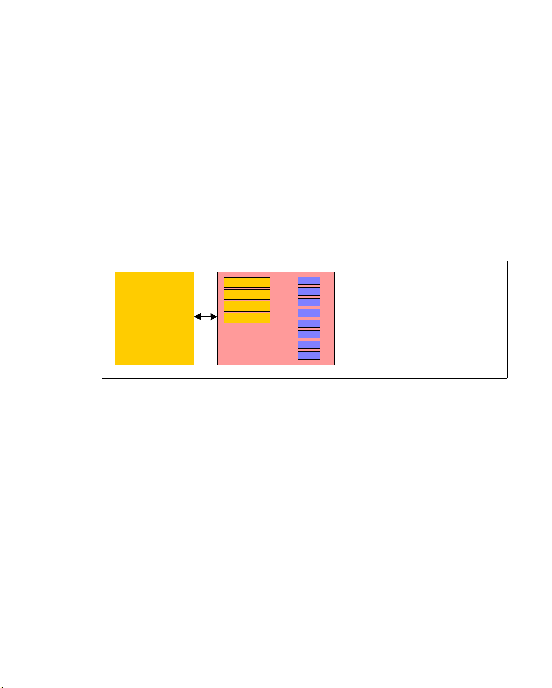
2.1 The CentricStor principle
Conventional host robot system
Drive
Drive
Drive
Drive
Host
Figure 1: Conventional host robot system
In a conventional real host robot system, the host system requests certain data cartridges
to be mounted in a defined real tape drive. As soon as the storage peripherals (robots,
drives) report that this has been completed successfully, data transfer can begin. In this
case, the host has direct, exclusive access to the drive in the archive system. It is crucial
that a completely static association be defined between the application and the physical
drive.
U41117-J-Z125-7-76 23
Robots
Data cartridges
Page 24
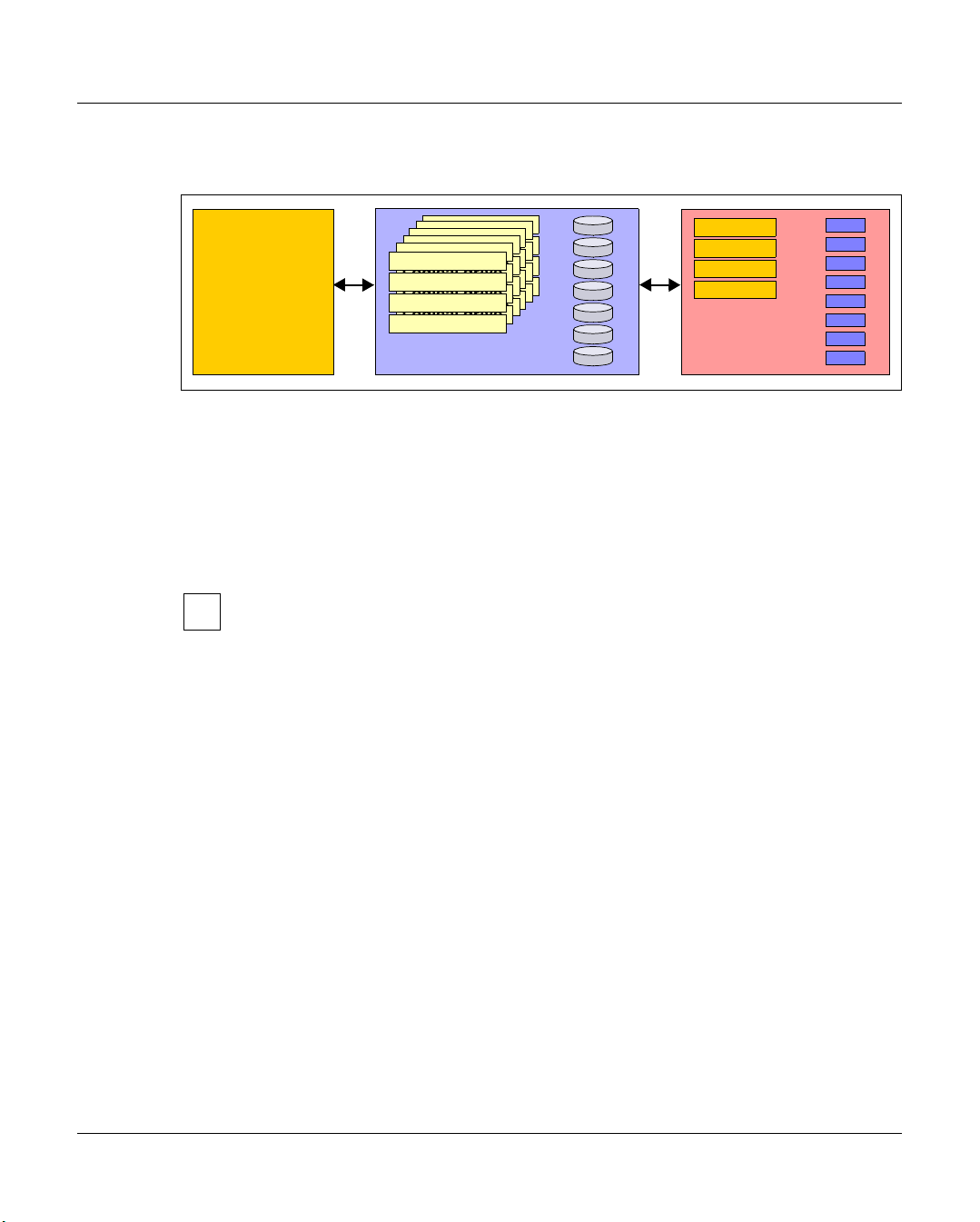
The CentricStor principle CentricStor - Virtual Tape Library
Host robot system with CentricStor
Logical drive
Logical drive
Logical drive
Logical drive
Logical drive
Logical drive
Logical drive
Logical drive
Logical drive
Logical drive
Logical drive
Logical drive
Logical drive
Logical drive
Logical drive
Logical drive
Logical drive
Logical drive
Logical drive
Logical drive
Logical drive
Logical drive
Logical drive
Logical drive
Host
Figure 2: Host robot system with CentricStor
CentricStor
logical volumes
Disk cache
Drive
Drive
Drive
Drive
Robots
Physical volumes
Data cartridges
With CentricStor, a virtual archive system is installed upstream of the real archive system
with the physical drives and data cartridges. This enables the host to be completely isolated
from the real archive. The virtual archive system contains a series of logical drives and
volumes. At its heart is a data buffer, known as the disk cache, in which the logical volumes
are made available. This guarantees extremely fast access to the data, in most cases
allowing both read and write operations to be performed much more efficiently than in
conventional operation.
Instead of the term logical drives (or volumes), the term virtual drives (or volumes)
i
is sometimes also used. These terms should be regarded as synonyms. In this
manual the term logical is used consistently when drives and volumes in
CentricStor are meant, and physical when the real peripherals are meant.
The virtual archive system is particularly attractive, as it provides a large number of logical
drives compared to the number of physical drives. As a result, bottlenecks which exist in a
real archive can be eliminated or avoided.
From the host’s viewpoint, the logical drives and volumes act like real storage peripherals.
When a mount job is issued by a mainframe application or an open systems server, for
example, the requested logical volume is loaded into the disk cache. If the application then
writes data to the logical drive, the incoming data stream is written to the logical volume
created in the disk cache.
The Library Manager of the virtual archive system then issues a mount job to the real
archive system asynchronously and completely transparently to the host. The data is read
out directly from the disk cache and written to a physical tape cartridge. The physical
volume is thus updated with optimum resource utilization.
Logical volumes in the disk cache are not erased immediately. Instead, data is displaced in
accordance with the LRU principle (Least Recently Used). Sufficient space for this must be
allocated in the disk cache.
24 U41117-J-Z125-7-76
Page 25

CentricStor - Virtual Tape Library The CentricStor principle
As soon as a mount job is issued, the Library Manager checks whether the requested
volume is already in the disk cache. If so, the volume is immediately released for processing
by the application. If not, CentricStor requests the corresponding cartridge to be mounted
onto a physical drive, and reads the logical volume into the disk cache.
CentricStor thus operates as a very large, extremely powerful, highly intelligent data buffer
between the host level and the real archive system.
It offers the following advantages:
● removal of device bottlenecks through virtualization
● transparency to the host thanks to the retention of interfaces unchanged
● support for future technologies by isolating the host from the archive system
CentricStor thus provides a long-term, cost-effective basis for modern storage
management.
U41117-J-Z125-7-76 25
Page 26
Hardware architecture CentricStor - Virtual Tape Library
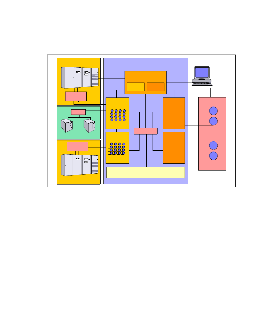
2.2 Hardware architecture
Mainframe
CentricStor
LAN
ESCON
Director
Switch
ESCON
FC
UNIX/Windows
FICON
Switch
FICON
Mainframe
Figure 3: Example of a CentricStor configuration
LAN
ICP
Virtual
tape drives
ICP
Virtual
tape drives
VLP
PLMVLM
FC Switch
TVC
LAN
IDP
IDP
CentricStor
Console
LAN
SCSI
SCSI
Real
tape drives
SCSI
SCSI
Real
tape drives
Robots
In this example, CentricStor comprises the following hardware components:
● a VLP (Virtual Library Processor), which monitors and controls the CentricStor
hardware and software components
● two ICPs (Integrated Channel Processors), which communicate with the hosts via
ESCON (via ESCON Director), FICON (via FICON switch) or FC (via FC switch)
● two IDPs (Integrated Device Processors), which communicate with the tape drives in
the robot system via SCSI or FC
● one or more RAID systems for the TVC (Tape Volume Cache) for buffering logical
volumes
● an FC switch, which is used by the ICP, IDP, and VLP to transfer data
● a CentricStor console for performing configuration and administration tasks
● a LAN connection between CentricStor and the robot system
● a LAN connection, which is used by the ICP, IDP, and VLP for communication
The PLM (Physical Library Manager) and VLM (Virtual Library Manager) are software
components which are particularly important for system operation (see page 34).
26 U41117-J-Z125-7-76
Page 27

CentricStor - Virtual Tape Library Hardware architecture
2.2.1 ISP (Integrated Service Processor)
CentricStor is a group of several processors, each running special software (UNIX
derivative) as the operating system. These processors are referred to collectively as the ISP
(Integrated Service Processor). Depending on the peripheral connection, the hardware
configuration, the software configuration, and the task in the CentricStor system, a
distinction is made between the following processor types:
– VLPs (optional: SVLP = standby VLP)
–ICPs
–IDPs
–ICP_IDP
To permit communication between the processors, they are interconnected by an internal
LAN. The distinguishing characteristics of these processors are described in the following
sections.
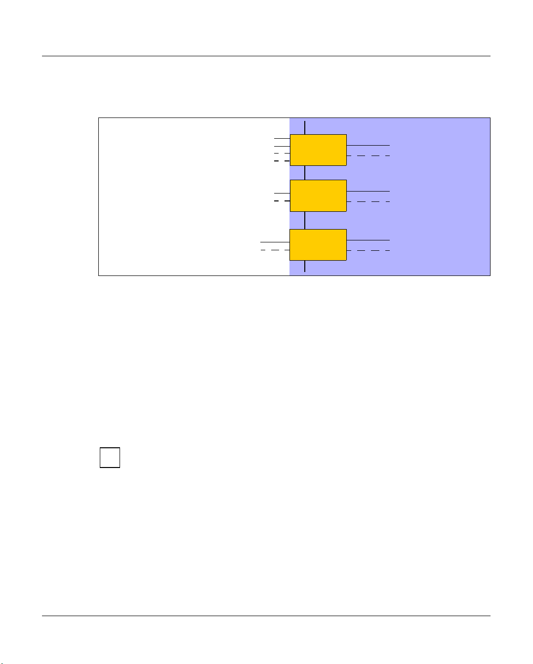
2.2.1.1 VLP (Virtual Library Processor)
The processor of the type VLP can be included twice to provide failsafe performance. Only
one of the two plays an active role at any given time: the VLP Master. The other, the Standby
VLP (SVLP), is ready to take over the role of the VLP Master should the VLP Master fail
(see section “Automatic VLP failover” on page 52). The two VLPs are connected to each
other and to the ICPs, IDPs and TVC via FC.
CentricStor
Figure 4: Internal VLP connections
The main task of the VLP Master is the supervision and control of the hardware and
software components, including the data maintenance of the VLM and the PLM. Communication takes place via the LAN connection
The software which controls CentricStor (in particular, the VLM and PLM) is
i
installed on all the processors (VLP, ICP, and IDP) but is only activated on one
processor (the VLP Master).
U41117-J-Z125-7-76 27
VLP
FC
FC
LAN
Page 28
Hardware architecture CentricStor - Virtual Tape Library
2.2.1.2 ICP (Integrated Channel Processor)
The ICP is the interface to the host systems connected in the overall system.
Hosts
BS2000/OSD,
ESCON
LAN
ICP
z/OS and OS/390
z/OS and OS/390
FICON
BS2000/OSD,
Open Systems
Figure 5: External and internal ICP connections
Depending on the type of host system used, it is possible to equip an ICP with a maximum
of 4 ESCON boards on the host side (connection with BS2000/OSD, z/OS or OS/390), with
one or two FICON ports (connection with z/OS or OS/390), or with one or two FC boards
(BS2000/OSD or open systems). A mixed configuration is also possible.The ICP also has
an internal FC board (or two in the case of redundancy) for connecting to the RAID disk
system.
The main task of the ICP is to emulate physical drives to the connected host systems.
The host application issues a logical mount job for a logical drive in an ICP connected to a
host system (see section “Issuing a mount job from the host” on page 39). The data trans-
ferred for the associated logical volume is then stored by the ICP directly in the RAID disk
system.
FCP
ICP
ICP
CentricStor
FC
FC
FC
FC
FC
FC
The virtual CentricStor drives support a maximum block size of 256 KB.
i
Communication with the other processors takes place over a LAN connection.
28 U41117-J-Z125-7-76
Page 29
CentricStor - Virtual Tape Library Hardware architecture
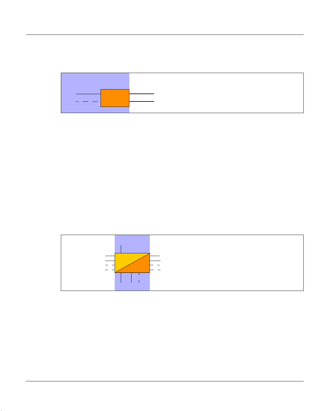
2.2.1.3 IDP (Integrated Device Processor)
The IDP is the interface to the connected tape drives.
CentricStor
FC
FC
Figure 6: Internal and external IDP connections
The IDP is responsible for communication with real tape drives. To optimize performance,
only two real tape drives should be configured per IDP.
Because of the relatively short length of a SCSI cable (approx. 25 m), the CentricStor IDPs
are typically installed directly in the vicinity of the robot archive if a SCSI connection is to be
used to connect the drives.
It is capable of updating tape cartridges onto which data has already been written by
appending a further logical volume after the last one.
A cartridge filled in this way with a number of logical volumes is also referred to as a stacked
volume (see section “Administering the tape cartridges” on page 35).
Communication with the other processors takes place over a LAN connection.
2.2.1.4 ICP_IDP or IUP (Integrated Universal Processor)
Hosts
IDP
SCSI or FC
SCSI or FC
RobotsCentricStor
Robots
Interfaces
to the host
An ICP_IDP provides the features of a VLP, an ICP and an IDP. This processor has interfaces to the hosts and to the tape drives.
However, the performance is a great deal lower than if its functions are distributed on its
own processors of the types VLP, ICP and IDP.
IUP (Integrated Universal Processor) is a synonym for ICP_IDP.
U41117-J-Z125-7-76 29
ICP_IDP
LAN
FC FC
Interfaces to
tape drives
Page 30
Hardware architecture CentricStor - Virtual Tape Library
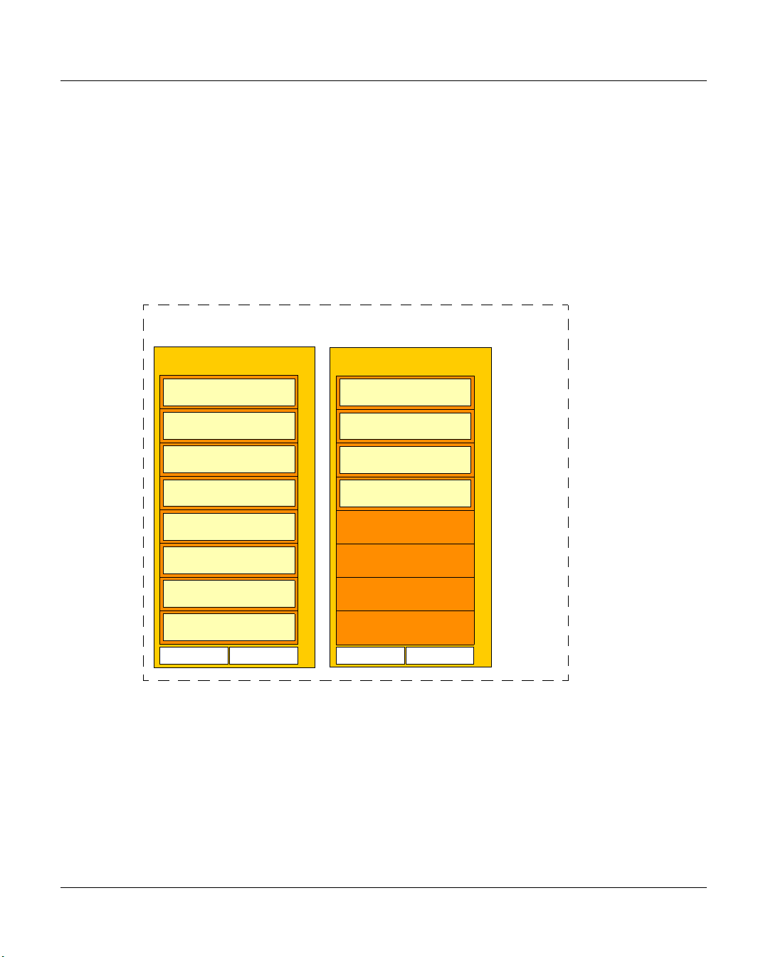
2.2.2 RAID systems for the Tape Volume Cache
A TVC (Tape Volume Cache) is the heart of the entire virtual archive system. It represents
all of the Tape File Systems in which the logical volumes can be stored temporarily. One or
more RAID systems (up to 8) are used for this.
Each RAID system contains at least the basic configuration, which consists of FC disks and
2 RAID controllers. It can also be equipped with up to 7 extensions, which in turn constitute
a fully equipped shelf with FC or ATA disks. A RAID system consists of shelves which in
CentricStor are always fully equipped with disks. The TVC illustrated in the figure below
contains 2 RAID systems with a total of 12 equipped shelves:
TVC
1st RAID system
basic config.
extension
extension
extension
extension
extension
extension
extension
Contr. 0 Contr. 1
Figure 7: 2 RAID systems form the TVC
2nd RAID system
Shelf
Shelf
Shelf
Shelf
Shelf
Shelf
Shelf
Shelf
basic config.
extension
extension
extension
Contr. 0 Contr. 1
Shelf
Shelf
Shelf
ShelfShelfShelfShelfShelf
In the case of the FibreCat CX3-20, for example, the 300-GB FC disks used offer a net capacity of 900 GB per RAID group. Here the basic configuration and each extension contain
3 RAID groups, resulting in a net capacity of 3 * 0.9 TB = 2.7 TB for each shelf. The net
capacity of the maximum configuration of a RAID system is therefore 8 * 2.7 TB = 21.6 TB.
One RAID group is used for one cache file system, which means that the basic configuration
and each extension contain 3 cache file systems and one RAID system with the maximum
configuration with 24 cache file sytems.
30 U41117-J-Z125-7-76
Page 31

CentricStor - Virtual Tape Library Hardware architecture
The metadata of the logical volumes to be written or read is stored on the 1st RAID system,
as a result of which the usable capacity of this RAID system is reduced by 16 GB.
A CentricStor can contain up to 8 RAID.
The number of cache file systems determines the number of logical volumes available (up
to 500,000). At least one cache file system is required for each 100,000 logical volumes.
The Cache Mirroring Feature (CMF) requires an additional cache file system for possible
recovery measures. Under these conditions the following minimum requirements consequently apply for logical volumes with the standard size of 900 MB:
Logical volumes Cache file systems required
100,000 At least 2
200,000 At least 3
300,000 At least 4
400,000 At least 5
500,000 At least 6
When larger logical volumes are used (2 - 200 GB, see the section “New system functions”
on page 43), correspondingly more cache file systems can be required. When the Cache
Mirroring Feature (see the page 55) is used, all cache file systems are mirrored to RAID
system pairs and therefore require double the disk resources. The capacity is therefore
reduced by 50%.
2.2.3 FibreChannel (FC)
The entire flow of data between all CentricStor components (ISPs and external RAID systems) is handled via an internal SAN which can provided with redundancy. It is implemented
by one high-performance FC switch or, if redundancy is provided, by two high-performance
FC switches.
2 FC technologies are available, Multi Mode and Single Mode. In Multi Mode the devices
which are connected via Fibre Channel can be located up to 300 m from each other; in Sin-
gle Mode the distance can be as much as 10 km. The FC controllers used in CentricStor
support bandwidths between 1Gb/s (Gigabits per second) and 4 Gb/s.
2.2.4 FC switch (fibre channel switch)
In the CentricStor models VTA 1500-5000, the entire flow of data between all CentricStor
components is handled by means of an FC switch.
U41117-J-Z125-7-76 31
Page 32

Software architecture CentricStor - Virtual Tape Library
This SAN-based design means that each CentricStor component is in a position to access
the TVC.
2.2.5 Host connection
The host connection on the ICP is implemented using the following connection
technologies:
Host system Operating system Connection
Mainframe BS2000/OSD ESCON or FibreChannel
z/OS and OS/390 ESCON or FICON
Bull ESCON
Unisys ESCON
Open Systems Reliant UNIX FibreChannel
Solaris FibreChannel
Microsoft Windows FibreChannel
AIX FibreChannel
HP-UX FibreChannel
FibreChannel with ESCON or FICON connections can be operated in mixed mode on an
ICP.
CAUTION!
!
Simultaneous operation of ESCON and FICON connections is not permitted on the
same ICP.
2.3 Software architecture
The functions VLP, ICP and IDP which are described in the following sections are not
necessarily separate hardware components.
In large CentricStor configurations (VTA 1500-5000) all functions are normally implemented
in separate hardware components. In smaller hardware configurations (VTA 500/1000,
VTC, SBU), several of these functions are implemented on one hardware component. In the
VTC all functions, including the RAID system, are combined in a hardware component.
If, for example, an ICP is designated an Integrated Channel Processor, this is to be understood as a function and not as a hardware component.
32 U41117-J-Z125-7-76
Page 33

CentricStor - Virtual Tape Library Software architecture
MSP/XSP
LIB/SP
z/OS
OS/390
HACC
CSC
BS2000
ROBAR
CSC
Open
Systems
ACSLS
DAS-ACI
SCSI
Backup
software
CentricStor
VLS
VLMF
VAMU
VAC S
VDAS
VJUK
1
VLM
VLP
TVC
PLM
PLS
PLS
PLS
PLS
ADIC
AMU/SDLC
DAS
StorageTek
ACSLS
Jukebox
Accessor
PLP
LMF LITE
CentricStor
console
Figure 8: Central role of the VLP in a CentricStor configuration1
VLP (Virtual Library Processor)
The VLP is responsible for the coordination of the entire CentricStor system. Although the
software can be activated on any of the ICP or IDP systems, it is recommended for performance reasons that you either provide a separate VLP, or activate the components of the
VLP on one of the IDPs, since the CPU utilization is at its lowest here.
The use of a second VLP (SVLP) is optionally possible.
1
VJUK runs on an ICP.
U41117-J-Z125-7-76 33
Page 34

Software architecture CentricStor - Virtual Tape Library
VLM (Virtual Library Manager)
Each robot job from the requesting host system is registered in the VLM. To support the
libraries, corresponding emulations (VLMF, VAMU, VACS, VDAS, VJUK) are used in
CentricStor.
The TVC is administered exclusively by the VLM.
The VLM data maintenance contains the names of the logical volumes with which the TVC
is to work.
PLM (Physical Library Manager)
The PLM coordinates all jobs issued to the connected peripherals (robot drives). The PLM’s
data maintenance facility stores information about where and on which physical volume
each logical volume is stored.
VLS (Virtual Library Service)
There may be various different instances of the VLS, depending on the type and number of
connected host systems:
Host connection Instance Library
BS2000/OSD, z/OS and OS/390 VAMU ADIC
Open Systems Server (UNIX, Windows) VDAS
CSC Clients of BS2000/OSD VAC S StorageTek
Open Systems Server (UNIX, Windows) with ACSLS
LIB/SP Clients from Fujitsu VLMF Fujitsu
Open Systems Clients, UNIX and Windows VJUK SCSI
PLS (Physical Library Service)
The PLS is the link between CentricStor and the robot archive. Jobs to the robots, e.g.
moving a tape cartridge in the robot archive, are issued at the behest of the PLM.
34 U41117-J-Z125-7-76
Page 35

CentricStor - Virtual Tape Library Operation
2.4 Operation
CentricStor is operated via the graphical user interfaces GXCC (Global Extended Control
Center) and XTCC (Extended Tape Control Center). These are used to perform all
administration and configuration tasks.
Using this control center, it is possible to display the current operating statuses of all
CentricStor components, together with a large amount of performance and utilization data.
For a description, refer to chapter “Operating and monitoring CentricStor” on
i
page 83, chapter “GXCC” on page 119 and chapter “XTCC” on page 325.
2.5 Administering the tape cartridges
Tape cartridge administration is performed separately by the PLM for each physical volume
group (PVG) (see also section “Partitioning on the basis of volume groups” on page 63).
Each PVG has its own scratch pool. All reorganization parameters can be set separately for
each PVG.
2.5.1 Writing the tape cartridges according to the stacked volume principle
The figure below shows the location of logical volumes on the magnetic tape:
Logical
volume 1
Figure 9: Position of the logical volumes on the magnetic tape
Each tape cartridge of the robot archive is administered by CentricStor as a stacked
volume, where a series of logical volumes is stored consecutively on the tape. In this way,
tapes are filled almost to capacity. There will be a small section of unused tape, since a
logical volume will always be written in full onto a physical tape cartridge (no continuation
tape processing).
U41117-J-Z125-7-76 35
Logical
volume 2
Logical
volume 3
Logical
volume 4
Page 36

Administering the tape cartridges CentricStor - Virtual Tape Library
2.5.2 Repeated writing of a logical volume onto tape
If a logical volume which has already been saved onto tape is written to tape a second time
following an update, the first backup will be declared invalid. The current volume is
appended after the last volume of this tape or another tape with sufficient storage space.
LV0013
Tape header
LV0008
Tape header
Figure 10: Repeated writing of a logical volume onto tape
In the example above, the logical volume LV0013 on physical volume PV0000 is declared
invalid and is written anew to physical volume PV0001.
2.5.3 Creating a directory
After each write operation a directory is created at the end of the tape. This permits highspeed data access during a later read/write operation.
LV0024
Tape-Header
Figure 11: Creating a directory on tape
LV0011
LV2008
LV0013
LV0002
LV2413
LV0021
Directory
PV0000
PV0001
Contents
36 U41117-J-Z125-7-76
Page 37

CentricStor - Virtual Tape Library Administering the tape cartridges
2.5.4 Reorganization of the tape cartridges
When a logical volume is released by the host’s volume management facility (e.g. MAREN
in BS2000/OSD), it is flagged accordingly in the CentricStor data maintenance facility which
contains the metadata for each volume. This process, combined with updates (see the
section section “Creating a directory” on page 36), will cause the areas containing invalid
data on the real tape cartridges to increase more and more over time (stacked volume with
gaps). If the number of scratch tapes for a CentricStor system falls below a configurable
lower limit, the PLM automatically performs a reorganization by using the VLM to load any
logical volumes still valid into the RAID system and then, so to speak, moving them
piecemeal onto scratch tapes.
LV0000 LV0001
LV0003
:
CentricStor
PLM
VLM
TVC
:
LV0037
LV0000 LV0001
LV0003
:
:
LV0037
LV0006 LV0007
Figure 12: Example of a reorganization
LV0004
LV0004
LV0001
LV0005
LV0010
LV0005
LV0010
LV0002
LV0006 LV0007 LV0008
LV0011LV0009
LV0002
LV0006 LV0007 LV0008
LV0011LV0009
LV0002
LV0003
LV0011LV0009
PV0000
PV0001
PV0002
:
:
PV0007
PV0008
PV0000
PV0001
PV0002
:
:
PV0007
PV0008
Read tape: Tape cartridge that still contains valid data but has no free space for write
operations
Scratch tape: Tape cartridge that only contains invalid data and has been released for
rewriting
Write tape: Tape cartridge that still contains space for write operations
Read tapes
Scratch tapes
Write tapes
U41117-J-Z125-7-76 37
Page 38

Procedures CentricStor - Virtual Tape Library
2.6 Procedures
2.6.1 Creating the CentricStor data maintenance
Initial situation: CentricStor is installed and configured. As yet, there is no data on the
RAID system. The tape cartridges of the robots are blank.
To start CentricStor, the PLM and VLM data maintenance facility must be created:
CentricStor
VLM PLM
PV0000
PV0001
1
PV0002
PV0003
PV0004
PV0005
PV0006
PV0007
PV0008
PV0009
PV0010
PV0011
RAID
2
Robots
Tape drive
Physical volumes
PV0012
PV0009
PV0006
PV0003
PV0000
PV0000
PV0000
PV0007
PV0004
PV0001
PV0000
PV0000
PV0008
PV0005
PV0002
Host
BS2000
CSC
ROBAR
MAREN
LV0000
LV0001
LV0002
LV0003
LV0000
LV0001
LV0002
LV0003
LV0004
LV0005
LV0006
LV0007
LV0008
LV0009
LV0010
LV0011
Logical volumes
3
Figure 13: CentricStor after the VLM and PLM data maintenance have been created
1. The names of the logical volumes which are to be loaded into the RAID disk array later
are entered in the VLM data maintenance (see the section “Logical Volume Operations
» Add Logical Volumes” on page 211).
In the example, these are the logical volumes LV0000 to LV2000. These volumes still
do not contain any data.
2. The names (VSNs) of the physical volumes present in the robots which are to be used
in CentricStor are entered in the PLM data maintenance (see the section “Physical
Volume Operations » Add Physical Volumes” on page 223). In the example, these are
the volumes PV0000 to PV0100.
3. The logical volumes are made known in BS2000/OSD (example of a storage location:
“VTLSLOC”).
CentricStor is then ready for operation.
38 U41117-J-Z125-7-76
Page 39

CentricStor - Virtual Tape Library Procedures
2.6.2 Issuing a mount job from the host
Initial situation: The logical volume LV0005 is already located on the physical volume
PV0002.
CentricStor
a
f
PV0000
LV0000
LV0001
5
e
LV0003
PV0001
LV0004
LV0017
PV0002
LV0027
LV0005
LV0013
PV0004
RAID
Logical volumes
LV0005
Data
d
b
Robots
c
Tape drive
PV0002
LV0027 LV0005
Physical volumes
PV0012
PV0009
PV0006
PV0003
PV0000
LV0000 LV0001
PV0000
PV0000
PV0007
PV0004
PV0001
LV0004 LV0017
PV0000
PV0000
PV0008
PV0005
PV0002
LV0061
LV0073
LV0013
LV0003
Host
LV0005
Data
2
VLM PLM
LV0000
LV0001 M
LV0002
LV0003
LV0004
LV0005
LV0006 M
LV0007
LV0008
LV0009 M
LV0010 D
LV0011
3
1
4
Figure 14: Procedure for a mount job
A mount job is executed as follows:
1. The host issues a mount job for logical volume LV0005, which is then accepted by the
VLM.
The VLM does not know at this point what task is involved:
– read the volume or a part thereof
– append a file to the end of the volume
– overwrite the entire volume
2. The VLM checks its data maintenance to establish whether the logical volume LV0005
specified by the host is available and whether there is a corresponding free storage
space on the RAID system.
If the RAID system does not have enough free capacity at this point, the LRU (Least
Recently Used) procedure is employed to delete the oldest data from the RAID system.
If a sufficient number of old files cannot be deleted, the mount job is suspended (“Mount
queued”).
U41117-J-Z125-7-76 39
Page 40

Procedures CentricStor - Virtual Tape Library
Depending on whether the logical volume is still in the RAID system or is only on
a physical volume, the following two situations arise:
Case 1: The volume is migrated to tape and is no longer located in the RAID system.
a) The VLM issues a request to the PLM to read the logical volume LV0005
into the RAID system.
b) The PLM checks its data maintenance to determine the physical volume
on which the requested logical volume LV0005 is located: PV0002.
c) The PLM requests the robot to mount the real tape cartridge PV0002
onto a free tape drive.
d) The data of the logical volume LV0005 is loaded from the tape drive into
the RAID system.
e) A flag is set in the VLM data maintenance to indicate that the logical
volume LV0005 is in the RAID system.
f) Only at this point does the VLM grant the host access to the volume
(mount acknowledged).
Case 2: The volume is present in the RAID system.
The VLM immediately grants the host access to the volume.
3. The host performs read and write accesses on the logical volume.
4. The host issues an unmount job.
In contrast to a real archive system, the job will be confirmed immediately.
i
5. The VLM checks whether the logical volume in the RAID system has been modified.
Case 1: The logical volume has not been modified.
No further action is taken, since the copy of the logical volume on the
physical volume is still valid.
40 U41117-J-Z125-7-76
Page 41

CentricStor - Virtual Tape Library Procedures
Case 2: The logical volume has been modified.
a) The VLM informs the PLM that the logical volume is to be copied onto
tape.
b) The PLM selects a suitable tape cartridge: a completely new tape, a
scratch tape, or a tape onto which writing has not yet resulted in an
overflow. If this cartridge is not yet mounted, the PLM checks whether a
real drive is available in the robot archive at this point.
c) The PLM requests the selected real tape cartridge to be mounted, if
required, and begins data transfer from the RAID system to the tape.
The data of the logical volume is retained on the RAID system until deleted by
i
the VLM in accordance with the LRU procedure.
U41117-J-Z125-7-76 41
Page 42

Procedures CentricStor - Virtual Tape Library
2.6.3 Scratch mount
To prevent reading in from the physical medium in cases where a logical volume is to be
rewritten anyway, under certain circumstances CentricStor performs a “scratch mount”.
The special features of the scratch mount in CentricStor are as follows:
– If the logical volume is migrated, i.e. it is no longer in the TVC, only a “stub” is made
available for the application. This stub contains only the tape headers.
– As this stub is always kept in the TVC a scratch mount can always be performed very
quickly as no restore is required from the physical tape.
– For the application this means that only access to the tape headers is possible.
If a scratch mount is performed incorrectly this can result in read errors when
i
an attempt is made to access the other data. In this case the data is not lost:
When a subsequent “normal” mount is performed it is available again.
CentricStor performs a scratch mount under the following conditions, depending on the
frontend (interface of the virtual library):
VAMU The mount command supports a flag which can be used to indicate that the
mount is to be performed as a scratch mount.
VDAS There is a special DAS_MOUNT_SCRATCH command (used only by FSC Networ-
ker). In this case CentricStor performs a scratch mount.
VACS A scratch mount is performed in the following two cases:
– “Mount_scratch” with the “pool-ID” parameter without specification of a par-
ticular volume
– Mount on a specific volume if this is contained in a pool whose pool ID is not
0
VLMF A scratch mount is performed in the following two cases:
– Mount with the “scratch” command with specification of a pool or specific vo-
lume
– Mount of a volume that is marked as “scratch”
VJUK No scratch mount is used
42 U41117-J-Z125-7-76
Page 43

CentricStor - Virtual Tape Library New system functions
2.7 New system functions
CentricStor Version 3.1C for the first time provides the option of creating logical volumes
(LVs) more than 2 GB in size as a standard feature. The LV size can be selected in discrete
steps for each logical volume group (LVG):
● STANDARD: 900 MB
● EXTENDED: 2 GB
5 GB
10 GB
20 GB
50 GB
100 GB
200 GB
The DTV file system must be migrated for CentricStor systems configured with
i
Version 3.0 or earlier. This is done by the service staff.
For the user, using large logical volumes is basically no different from the way logical
volumes have been used to date.
The following special aspects must be taken into consideration:
– The LV size of an existing LVG can be increased if the PVs (physical volumes) of the
PVG (physical volume group) which is linked to the LVG has the necessary capacities
(see the section “Logical Volume Groups” on page 173).
– The LV size of an existing LVG cannot be decreased (see the section “Logical Volume
Groups” on page 173).
– The size of the LVG "TR-LVG" cannot be modified (see the section “Logical Volume
Groups” on page 173).
– An LVG with LVs > 2 GB can be assigned to a PVG only if the capacity of the PVs
already assigned is twice as large as the LV size (see the section “Physical Volume
Operations » Link/Unlink Volume Groups” on page 221).
– PVs can be assigned to a PVG only if their capacity is greater than or equal to the LV
size of the LVG which is linked to the PVG (see the section “Physical Volume Opera-
tions » Add Physical Volumes” on page 223).
– The TVC must be large enough to permit the use of large LVs. If the TVC is too small,
frequent displacement of LVs must be reckoned with. This can have a significant effect
on the LV mount times depending on the volume size and the drive type (e.g. with 200
GB approx. 90-120 min.).
U41117-J-Z125-7-76 43
Page 44

Standard system functions CentricStor - Virtual Tape Library
2.8 Standard system functions
The following functions are standard in every CentricStor system:
● Partitioning by volume groups
● “Call Home” in the event of an error
● SNMP support
● Exporting and importing tape cartridges
2.8.1 Partitioning by volume groups
CentricStor supports a volume group concept. This provides the following benefits:
– It can be ensured that the copies of a logical volume created by an application are
stored on two different physical volumes (data security in case a magnetic tape
cartridge becomes unreadable).
– The storing of logical volumes of different host systems or applications on one and the
same magnetic tape cartridge can be prevented.
The volume group concept is a prerequisite for “Dual Save” (see the section “Dual Save” on
page 50).
2.8.2 “Call Home” in the event of an error
In the event of serious errors in CentricStor operation, the following measures are initiated
automatically:
– The error is reported to a hotline using “Call Home”.
In the event of connection via ROBAR, information is also sent to the BS2000 host via
“Hot Messages”.
– The error report can be transferred to a Service Access System (SAS) so that specific
responses can be triggered there. In addition, it is possible to send an SMS when
certain messages are issued.
– The responses to the individual error events are preset for various service provider pro-
files. One of these can be selected. In addition, the selected default can be adjusted on
a customer-specific basis.
44 U41117-J-Z125-7-76
Page 45

CentricStor - Virtual Tape Library Standard system functions
2.8.3 SNMP support
It is possible to integrate CentricStor into remote monitoring by an SNMP Management
Station such as “CA Unicenter” or “Tivoli”.
In the event of system errors (error weighting EMERGENCY, ALERT, ERROR, CRITICAL),
CentricStor sends a trap to the SNMP Management Station, which causes the CentricStor
icon to change color (insofar as this is supported by the SNMP Management Station).
Furthermore, a status trap with the weightings green, yellow and red is sent periodically to
the Management Station.
Application launching enables the CentricStor administration software “GXCC” to be
started simply on the SNMP Management Station by means of a mouse click.
2.8.4 Exporting and importing tape cartridges
The options for exporting and importing tape cartridges (physical volumes) which are
offered by CentricStor can be used for various purposes:
● Storing the backup data at a disaster-proof location, e.g. in a fire-resistant room or at a
large distance from the CentricStor system
● Manual archiving of data which is accessed extremely rarely, e.g. because it is only re-
quired when a disaster occurs
● Exchanging data between independent systems at separate locations in order to guard
against local disaster sby means of redundant data storage
● Transfer of bulk data when extremely large distances are involved in order to save on
line costs or if there is a lack of infrastructure
Two standard functions are available for exporting/importing tape cartridges:
● Setting the vault attribute for a physical volume group (PVG) and setting the vault status
for a physical volume (PV)
● Use of the transfer PVG (TR-PVG)
These functions are totally separate from the tape management tool of the host applications
and are controlled solely by the CentricStor system administrator.
U41117-J-Z125-7-76 45
Page 46

Standard system functions CentricStor - Virtual Tape Library
2.8.4.1 Vault attribute and vault status
The vault attribute is assigned to a physical volume group (PVG) by means of the GXCC
function Configuration ➟ Physical Volume Groups in the Type entry field (see page 187). The
associated tape cartridges (PVs) can be placed in vault status using the following command:
plmcmd conf -E -V <PV> -G <PVG>
They are then locked for all read and write operations until vault status is cancelled again
using the following command:
plmcmd conf -I -V <PV> -G <PVG>
While vault status is set, the tape cartridges can be removed from the tape library and
stored at a safe location (hence the status name vault). However, like all the logical volumes
contained on them, they are still administered by CentricStor.
An attempt to read from a tape cartridge which is in vault status is responded to with the
system message SXPL049 (see page 88). When a logical volume (LV) of such a tape cartridge is saved again by a host application, a different tape cartridge is used and the old LV
on the vault tape cartridge is flagged as invalid. Tape cartridges in vault status are also excluded from reorganization (see section “Reorganization” on page 73).
2.8.4.2 Transfer PVG
A so-called transfer PVG and a transfer LVG which is linked to this are permanently installed
in CentricStor for this export/import function. The logical or physical columes which are to
be exported or imported are temporarily added to these volume groups.
The LVs to be exported are also copied to tape cartridges of the transfer PVG. The original
LVs continue to belong to their former LVG. Their backup to tape cartridges of the PVG assigned to this LVG and access by the host applications are not affected by the export.
The system administrator alone is reponsible for controlling the copy operation for the LVs
concerned and for synchronizing this operation with their use by the host applications. CentricStor keeps no management data for these copy operations and does not know whether
or not an LV was exported via a transfer PVG.
When the required LVs have been copied, the tape cartridges can be removed from the
transfer PVG and transported to another CentricStor system. There the tape cartridges are
added to the transfer PVG and the LVs contained on them are read in. To do this it is necessary that all these LVs should already exist and be assigned to a normal LVG.
Further information on the export/import function via transfer PVG is provided in section
“Transferring volumes” on page 562.
46 U41117-J-Z125-7-76
Page 47

CentricStor - Virtual Tape Library Optional system functions
2.9 Optional system functions
CentricStor is available in a variety of configuration levels, in each of which further
customer-specific extensions (e.g. larger disk cache) are possible.
In addition to the basic configuration, optional functions are available which allow you to
customize the CentricStor functionality to suit your needs:
● Compression
● Multiple library support
● Dual Save
● Extending virtual drives
● System administrator’s edition
● Fibre channel connection for load balancing and redundancy
● Automatic VLP failover
● Cache Mirroring Feature
● Accounting
These optional system functions are released by means of key disks.
U41117-J-Z125-7-76 47
Page 48

Optional system functions CentricStor - Virtual Tape Library
2.9.1 Compression
The figure below illustrates the principle of software compression of logical volumes:
Data
from
host
Figure 15: Principle of compressing logical volumes
ICP
EMTAPE
VTD
Logical
volumes
TVC
Just as a physical drive can perform data compression, so also can the tape drive emula-
1
tions (EMTAPE
or VTD2) once they have been released3 on the ICP. In this way, the logical
volumes can be stored in compressed form in the TVC. This results in a whole range of
advantages:
● Disk cache utilization is significantly improved depending on the compression level, i.e.
without changing the cache size, it is possible to keep considerably more logical
volumes “online” in the cache than without compression, frequently resulting in a very
high-performance response time vis-à-vis the host system.
● The performance of the overall system is improved due to the fact that the load on the
FC network is reduced by the compression factor.
● In the case of data quantities greater than 900 MB, the number of logical volumes is
reduced.
Example (Standard)
To save a 4 GB file on standard volumes (900 MB) without compression, you will
need five logical volumes. If we assume a compression factor of 3, then only two
logical volumes will be necessary.
● Within the CentricStor migration concept (i.e. the relocation of volumes from the real
robot archive to the CentricStor archive while retaining the volume number), it is
currently necessary to identify all volumes whose size exceeds 800 MB after hardware
compression. If software compression is switched on for the logical drives, however,
then automatic 1:1 conversion will also be possible for these volumes.
Compression can be set separately for each drive (this is done using Service).
The “Compression” attribute can be set to “ON”, “OFF” or “HOST” for each drive.
1
Mainframes
2
Open systems
3
Compression only works with a block size of at least 1 Kbyte.
48 U41117-J-Z125-7-76
Page 49

CentricStor - Virtual Tape Library Optional system functions
In BS2000/OSD (“HOST” attribute), compression is controlled on the basis of the tape type:
– TAPE-C3: compression off
– TAPE-C4: compression on
In UNIX, the compression setting can be selected by the device nodes.
The compression setting can be passed in ESCON or SCSI command to the tape
emulation, and the compressed data is stored block-by-block on the logical volume (the
VLM and PLM do not have any information about this).
If the data is already compressed on the host, e.g. if backup data is supplied in
i
compressed format by a NetWorker client, then compression should be switched off
for this logical volume on the ICP, so that the load on the CPU of the ICP can be kept
to a minimum.
2.9.2 Multiple library support
One of the important characteristics of CentricStor is the parallel connection of multiple real
robot archives of different types.
Host1
Host2
Hosts
CentricStor
ADIC
Figure 16: Example of multiple library support
The number of robot archives that can be operated in parallel is theoretically unlimited.
However, since at least one physical volume group is required per library, it is only possible
to support as many libraries as there are corresponding volume groups.
StorageTek
IBM Cashion
Fujitsu robot
Robot archive
U41117-J-Z125-7-76 49
Page 50

Optional system functions CentricStor - Virtual Tape Library
All supported robot archive types are permitted:
– ADIC AML systems (with DAS)
– ADIC scalar systems (with DAS or SCSI)
– StorageTek systems (with ACSLS or SCSI)
–IBM Cashion
– Fujitsu robot (with LMF)
Please refer to the current product information for the library and drive type configurations
currently available. It is possible to have different drive types within the same archive.
However, a separate physical volume group must be configured for each drive type (see
section “Partitioning on the basis of volume groups” on page 63).
2.9.3 Dual Save
Based on the volume group functionality (see page 63), CentricStor offers the Dual Save
function. This involves making a copy of a logical volume on a second physical volume,
which may be located either in the same robot archive (Dual Local Save) or in a remote
robot archive (Dual Remote Save). This ensures the highest possible level of data security.
If a physical volume which usually contains a large number of logical volumes is in some
way corrupted (e.g. due to a tape error), CentricStor can access a copy of this logical
volume created on a different physical volume. If the copy is located in a second robot
archive, then even the complete destruction of the first robot archive would not cause any
irrevocable loss of data.
In many computer centers, for example, it is currently common practice to move the
volumes written during a backup operation (or copies generated by the application) to a
secure location directly on completion of the backup. The Dual Remote Save functionality
provides an elegant means of automating this procedure. Not only does it relieve the host
application of any copy or move operations, it also eliminates the need to transport the
cartridges to a second archive (and back again). The associated risk of data manipulation
is thus excluded.
50 U41117-J-Z125-7-76
Page 51

CentricStor - Virtual Tape Library Optional system functions
Host1
Host2
LVG 1
LVG 1 LVG 2
LV0001
LV0002
LV0003
...........
LV3000
PVG 1
PV0001
PV0002
PV0003
...........
PV0300
CentricStor
PVG 2
PV0301
PV0302
PV0303
...........
PV0600
LV3001
LV3002
LV3003
...........
LV6000
PVG 3
PV0701
PV0702
PV0703
...........
PV0800
Archive1
Figure 17: Example of Dual Save functionality
LVG 2
PVG 4
PV0801
PV0802
PV0803
...........
PV0900
Archive2
In accordance with the assignment rules for the volume group functionality (see page 64),
the logical volumes from LVG 1 (LV0001-LV3000) are mirrored on the physical volumes of
PVG 1 (PV0001-PV0300) and PVG 2 (PV0301-PV0600) in the robot Archive1. The logical
volumes of LVG 2 (LV3001-LV6000) are duplicated in Archive1 on PVG 3 (PV0701PV0800) and in Archive2 on PVG 4 (PV0801-PV0900), where the two robots are located
some distance apart.
U41117-J-Z125-7-76 51
Page 52

Optional system functions CentricStor - Virtual Tape Library
2.9.4 Extending virtual drives
This option allows you to increase the number of logical drives from the standard 32 per ICP
to up to 64 per ICP. This makes it possible to operate up to 256 logical drives in a single
CentricStor system.
2.9.5 System administrator’s edition
The “System Administrator Edition” (SAE) option provides a graphical user interface for
administering the CentricStor system from a remote PC workstation.
The operator PC is included as part of the scope of delivery. This machine can be used to
monitor a number of CentricStor systems.
2.9.6 Fibre channel connection for load balancing and redundancy
This option provides the CentricStor system with a second internal FC network for data
transfer. This enables operation to be continued without interruption even when a switch
fails (in normal operation the data stream is distributed to both switches).
2.9.7 Automatic VLP failover
Typically almost all CentricStor control functions run on the VLP. This processor is largely
protected against disk errors by RAID system disks. If this processor were to fail nevertheless, the CentricStor system would have no controller and thus no longer be operable.
Ongoing save jobs would be completed, but new ones would no longer be accepted.
To prevent this situation occurring, the “automatic VLP failover” function is provided
(AutoVLP failover).
A release via key is required for the "automatic VLP failover" function, and the SVLP
i
must be configured to use it. This is done by the maintenance staff.
Further prerequisites:
– The VLP and the standby processor SVLP must be equipped with an external and an
internal LAN interface.
– The standby processor SVLP must be equipped and configured like the VLP.
52 U41117-J-Z125-7-76
Page 53

CentricStor - Virtual Tape Library Optional system functions
If the “automatic VLP failover” function has been activated, the following actions are
i
no longer permitted in the system:
– changing the LAN configuration
– rebooting or shutting down of the VLP (init 0 or init 6: these commands
cause a failover!)
– disconnecting a LAN or FC cable
If the VLP fails, the scenario is as follows:
1. The VLP fails in the CentricStor system:
ISP
VLP
SVLP
ISP
FC fabric
Figure 18: Failure of the VLP
The SVLP is active in the system and monitoring the VLP. If the VLP fails, the SVLP
takes over control of CentricStor.
2. The SVLP is activated automatically:
ISP
Activation
SVLP
ISP
FC fabric
Figure 19: Activation of the SVLP using the AutoVLP failover function
During the switchover operation, which can last up to 5 minutes, this procedure is interpreted on the host side as a mount delay and a new connection setup to the robot
control. All backup jobs continue to run normally.
The switchover involves reconfiguring the two ISPs (VLP/SVLP): they swap their external IP addresses and tasks.
U41117-J-Z125-7-76 53
Page 54

Optional system functions CentricStor - Virtual Tape Library
3. After the defective processor has been repaired, it is integrated once again into the
overall system and takes over the role of the SVLP:
ISP
Figure 20: Activation of the defective processor for the SVLP
The status, i.e. AutoVLP failover active or inactive, is clearly visible on the GUI:
Figure 21: Display of the AutoVLP failover status on the GUI
The left-hand triangle is only displayed if an SVLP is configured.
SVLP
Activation
FC fabric
VLP
ISP
i
If the left-hand triangle below the VLP is green, this means that AutoVLP failover is
activated. If it is red, AutoVLP failover is not activated. In addition, the text “AutoVLPFailover OFF” is displayed in red in the text window on the right.
CAUTION!
!
The function must have the same status on the VLP and SVLP: enabled or not
enabled (ON or OFF).
When the AutoVLP failover function is configured and activated, VLP monitoring on this ISP
is activated automatically with every reboot.
54 U41117-J-Z125-7-76
Page 55

CentricStor - Virtual Tape Library Optional system functions
2.9.8 Cache Mirroring Feature
2.9.8.1 General
CentricStor V3.1 provides users with enhanced data security and greater protection against
data loss through disasters, promptly for all nearline data. Data stored on the internal hard
disk system is mirrored synchronously to a second cluster location. This is done via 2-Gbit
FibreChannel connections, also over long distances. Even if one location is totally
destroyed, all the saved data is available which is backed up on a CentricStor configuration
of this type. As the status of the data is at all times identical on both systems, a restart is
significantly quicker and simpler. No modifications to applications or data backup processes
are required.
2.9.8.2 Hardware requirements
A functioning mirror always requires two RAID systems. In CentricStor a maximum of 8
RAID systems are supported, i.e. a maximum of 4 RAID system pairs can be set up for
mirroring.
By definition a RAID system pair can only be set up when the following conditions apply:
● The RAID IDs begin with an odd ID.
● The RAID IDs of these systems are in unbroken ascending order.
As a result, a maximum of four possible RAID ID pairs are possible: 1+2, 3+4, 5+6 and 7+8.
A CentricStor system can contain two possible types of RAID mirror pairs:
– Potential mirror pairs
These pairs do satisfy the above-mentioned hardware requirements, but secondary
caches (mirror caches) must also be provided by a corresponding LUN assignment
(see the section “Mirrored RAID systems” on page 57). This is done by customer
support.
Potential mirror pairs can be recognized in GXCC by a thicker, black separating line (see
the section “Presentation of the mirror function in GXCC” on page 58).
– Genuine mirror pairs
These pairs satisfy all hardware requirements. They contain primary and secondary
caches (section “Mirrored RAID systems” on page 57) and are identified in GXCC by a
white dot (see the section “Presentation of the mirror function in GXCC” on page 58).
U41117-J-Z125-7-76 55
Page 56

Optional system functions CentricStor - Virtual Tape Library
2.9.8.3 Software requirements
The “vtlsmirr” key must have been read in and enabled for the mirror function. This is done
by customer support.
Assuming that the hardware requirements are satisfied (see the section above) and the
RAID systems have been defined by the corresponding LUN assignment (see the section
“Mirrored RAID systems” on page 57), the overall system is configured as a mirror system
solely through the existence of the key. No operator intercvention is required for this
purpose.
Example
After the mirror key has been read into a CentricStor system with 6 RAID systems, the
following configuration is established:
RAID mirror pair 1
1stRAID 2ndRAID
ID 1 ID 2
Genuine pair Potential pairGenuine pair
Figure 22: “Genuine” and “potential” RAID mirror pairs in a CentricStor system
RAID mirror pair 2
3rdRAID 4thRAID
ID 3 ID 4
RAID mirror pair 3
5thRAID 6thRAID
ID 6 ID 7
The first and second RAIDs and also the third and fourth RAIDs form genuine mirror pairs
as the IDs here begin with an odd number and are in unbroken ascending order.
The RAID systems with IDs 6 and 7 do not satisfy the hardware requirements and therefore
form a potential pair. They can be turned into a genuine mirror pair by changing ID 7 to ID 5.
56 U41117-J-Z125-7-76
Page 57

CentricStor - Virtual Tape Library Optional system functions
2.9.8.4 Mirrored RAID systems
A mirrored CentricStor system has 1 to a maximum of 4 RAID mirror pairs.
RAID mirror pair 1
1stRAID 2ndRAID
ID 1 ID 2
RAID mirror pair 2
3rdRAID 4thRAID
ID 3 ID 4
RAID mirror pair 3
5thRAID 6thRAID
ID 5 ID 6
Figure 23: Example of a CentricStor mirror system with 3 RAID mirror pairs
In a RAID mirror pair, one RAID system contains only primary caches, the other only
secondary caches (mirror caches):
RAID mirror pair
1st RAID
Primary
cache
Figure 24: Primary and secondary caches in a RAID mirror pair
2nd RAID
Secondary
cache
Example of the LUN assignments:
1st RAID 2nd RAID
(P) LUN0
(P) LUN1
(P) LUN2
(P) LUN3
(P) LUN4
(P) LUN5
(P) LUN6
(P) LUN7
(S) LUN8
(S) LUN9
(S) LUN10
(S) LUN11
(S) LUN12
(S) LUN13
(S) LUN14
(S) LUN15
P = Primary cache
S = Secondary cache
Such a mirror pair is defined by the corresponding assignment of the LUNs, as shown in the
example (where x is in the range 0 through 7) below:
Assignment of the LUNs for DTV
caches (/cache/...)
1st RAID 2nd RAID
(P) x + 0 (S) x + 8
(P) x + 1 (S) x + 9
(P) x + 2 (S) x + 10
(P) x + 3 (S) x + 11
(P) x + 4 (S) x + 12
(P) x + 5 (S) x + 13
(P) x + 6 (S) x + 14
(P) x + 7 (S) x + 15
U41117-J-Z125-7-76 57
Page 58

Optional system functions CentricStor - Virtual Tape Library
2.9.8.5 Presentation of the mirror function in GXCC
In GXCC the mirror functions of a double RAID system are indicated by two arrows.
Example
Figure 25: Presentation of the mirror function in GXCC
Genuine RAID pairs are indicated with a white dot, potential pairs by a thicker black line
between the boxes on the right-hand side
The display can contain an odd number of RAID systems if, for example, a defective
i
RAID system has been separated from the CentricStor system. Further information
on this is provided in the section “RAID symbol for mirror mode” on page 131.
58 U41117-J-Z125-7-76
Page 59

CentricStor - Virtual Tape Library Optional system functions
2.9.9 Accounting
On the one hand this function permits the accounting data of logical volume groups to be
displayed in GXCC (see the section “Statistics » Usage (Accounting)” on page 293).
Example
On the other hand this function enables the current accounting data to be sent by e-mail at
defined times (see the section “Setup for accounting mails” on page 229).
U41117-J-Z125-7-76 59
Page 60

Eine Dokuschablone von Frank Flachenecker
by f.f. 1992
Page 61

3 Switching CentricStor on/off
IMPORTANT!
!
The vendor recommends that CentricStor should not be switched off. This should
only be done in exceptional circumstances.
3.1 Switching CentricStor on
Before switching CentricStor on, you must ensure that the units with which
i
CentricStor is to communicate, i.e. host computers, ROBAR-SV systems (in the
case of host connection via ROBAR), the robot control processor, and the tape
robots are already up and running.
The following sequence must be followed when switching on the individual CentricStor
components:
1. Switch on the LAN hubs and switches (see corresponding operating instructions).
2. Switch on the fibre channel switches (see corresponding operating instructions).
When connecting open systems:
i
The external FC switches must now also be switched on, as otherwise the
ICPs will not establish a point-to-point connection.
3. Switch on the RAID systems (see corresponding operating instructions).
Wait a minute after the “System Ready” status has been reached after the RAID systems have been started up.
4. Switch on the ICPs/IDPs/VLP by pressing the POWER ON/OFF button:
Figure 26: POWER ON/OFF button on the ISP (example TX300)
U41117-J-Z125-7-76 61
Page 62

Switching CentricStor off Switching CentricStor on/off
Using GXCC or XTCC check that all the necessary CentricStor processes are running
(all processor boxes must be green).
5. BS2000/OSD:
Case 1: Host connection via ROBAR
Ê Start ROBAR-SV (with the menu program robar or robar_start; see
ROBAR manual [3]).
Case 2: Host connection via CSC
Ê Start CSC (see CSC manual [4]).
3.2 Switching CentricStor off
CentricStor can be switched off only in Service mode! As this mode is explained in
i
the CentricStor Service Manual, only a brief description is provided below.
The following sequence must be followed when switching off the individual CentricStor
components:
1. BS2000/OSD, z/OS and OS/390:
DETACH or VARY OFFLINE all logical drives on the host.
2. CentricStor is switched off via the GXCC user interface:
Ê Activate the “Shutdown” function (see the Service Manual).
All CentricStor processors (VLP, IDPs, ICPs) and - if the “power off” option is
activated - the connected RAID system are then shut down gracefully and switched
off.
Ê Wait for 5 minutes.
3. Switch off the hubs/switches (see corresponding operating instructions):
– LAN hubs
– fibre channel switches
62 U41117-J-Z125-7-76
Page 63

4 Selected system administrator activities
4.1 Partitioning on the basis of volume groups
4.1.1 General
By partitioning on the basis of volume groups, it is possible to combine certain logical
volumes to form a logical volume group (LV G) and certain physical volumes to form a
physical volume group (PVG).
Using rules which create associations between logical and physical volume groups, it is
possible to have CentricStor copy the logical volumes belonging to a particular LVG exclusively onto the physical volumes of the assigned PVG.
Partitioning on the basis of volume groups offers the following advantages:
● It allows you to store the logical volumes of various host systems or applications on
different physical volumes.
● In the case of Dual Save
different physical volumes. This offers an extra degree of data security for situations
where a tape becomes unreadable, for example (see section “Dual Save” on page 71).
Normally CentricStor has four volume groups:
1
, it allows you to store copies of a logical volume on two
– the logical volume group “BASE”
– the physical volume group “BASE”
– the logical volume group “TR-LVG”
– the physical volume group “TR-PVG”
The TR-LVG and TR-PVG volume groups are used to transfer logical and physical volumes
(see the section “Transferring volumes” on page 562).
Each physical volume group has its own local free pool from which new volumes
i
can be taken as the need arises and to which freed volumes can be returned
(e.g. following reorganization).
1
This assumes that the Dual Save functionality has been released (see page 71).
U41117-J-Z125-7-76 63
Page 64

Partitioning on the basis of volume groups Selected system administrator activities
You have two different systems (a BS2000
BS2000 host
UNIX system
host and a UNIX system) using CentricStor
in conjunction with an archive system. By
grouping volumes, it is hoped to achieve a
situation where BS2000 data and UNIX
LVG 1
LV0001
LV0002
LV0003
...........
LV3000
CentricStor
LVG 2
LV3001
LV3002
LV3003
...........
LV6000
data are stored on different physical
volumes.
The logical volumes of the BS2000 host are
assigned to the logical volume group LVG1,
while those of the UNIX system are
assigned to the logical volume group LVG2.
These logical volumes can (but need not
necessarily) be assigned to various physical
PVG1
Archive
PV0001
PV0002
PV0003
...........
PV0300
Figure 27: Example of partitioning on the basis of volume groups
BS2000
data
UNIX
Data
PVG2
PV0501
PV0502
PV0503
...........
PV0600
volume groups.
As a result of these assignments, BS2000
data will now be stored on the physical
volumes PV0001 through PV0300, while
UNIX files will be stored on the physical
volumes PV0501 through PV0600.
4.1.2 Rules
Logical volume groups:
– It is possible to configure up to 512 logical volume groups.
By default, CentricStor always has at least two logical volume groups (“BASE”
i
and “TR-LVG“). These are available in addition to the freely configureable
volume groups.
– Each logical volume in CentricStor belongs to precisely one logical volume group.
64 U41117-J-Z125-7-76
Page 65

Selected system administrator activities Partitioning on the basis of volume groups
Physical volume groups:
– It is possible to configure up to 100 physical volume groups1.
By default, CentricStor always has at least two physical volume groups (“BASE”
i
and “TR-LVG”). These exist in addition to the freely configurable volume groups.
– All physical volumes of a physical volume group belong to the same physical library.
– A physical volume group does not possess any tape drives, it is instead linked to a tape
library. This tape library can be part of a real tape library, and may only contain tape
drives of a single type.
– A physical library can contain several physical volume groups.
4.1.3 System administrator activities
This section contains brief information on the main system administrator activities:
– “Adding a logical volume group” on page 66
– “Adding a physical volume group” on page 66
– “Adding logical volumes to a logical volume group” on page 66
– “Adding physical volumes to a physical volume group” on page 67
– “Assigning an LVG to a PVG” on page 67
– “Removing an assignment between an LVG and a PVG” on page 67
– “Changing logical volumes to another group” on page 68
– “Removing logical volumes” on page 68
– “Removing logical volume groups” on page 68
– “Removing physical volumes from a physical volume group” on page 69
– “Removing physical volume groups” on page 69
1
Cleaning and transfer groups are not included here.
U41117-J-Z125-7-76 65
Page 66

Partitioning on the basis of volume groups Selected system administrator activities
4.1.3.1 Adding a logical volume group
● The form and detailed information are provided in the section “Logical Volume Groups”
on page 173
1. Click on the “NEW” button.
2. The following must be entered:
Name Name of the new logical volume group
Type Extended (2 GB, ... , 200 GB) or standard (900 MB)
Location Cache area (floating or defined explicitly)
Comment Comment
3. Click on the “OK” button.
The entries become effective with the next “Distribute and Activate” (see page 188).
4.1.3.2 Adding a physical volume group
● The form and detailed information are provided in the section “Physical Volume Groups”
on page 181.
1. Click on the “NEW” button.
2. A large number of entries need to be made. The description of the individual fields
is provided on page 183.
You will find further information in the section “Creating a new physical volume
group” on page 187.
3. Click on the “OK” button.
The entries become effective with the next “Distribute and Activate” (see page 188).
4.1.3.3 Adding logical volumes to a logical volume group
● The form and detailed information are provided in the section “Logical Volume Opera-
tions » Add Logical Volumes” on page 211.
The following information must be specified:
– the VSN of the first logical volume
– the logical volume group
– the number of logical volumes
The logical volumes are then incorporated in the CentricStor pool.
66 U41117-J-Z125-7-76
Page 67

Selected system administrator activities Partitioning on the basis of volume groups
4.1.3.4 Adding physical volumes to a physical volume group
Only physical volumes contained in the physical library may be specified.
i
● The form and detailed information are provided in the section “Physical Volume Opera-
tions » Add Physical Volumes” on page 223.
The following information must be specified:
– the VSN of the first physical volume
– an entry specifying whether the header of the added volume should be uncondi-
tionally overwritten with a CentricStor header
– the physical volume group (see section “Adding a physical volume group” on
page 66)
– the number of physical volumes
– the type of physical volumes
The physical volumes are then incorporated in the CentricStor pool.
4.1.3.5 Assigning an LVG to a PVG
● The form and detailed information are provided in the section “Physical Volume Opera-
tions » Link/Unlink Volume Groups” on page 221.
The following elements must be selected:
– the logical volume group
– the physical volume group (original)
– a second physical volume group (copy, only applies for “Dual Save”)
The logical volume group is then assigned to the selected physical volume group(s).
4.1.3.6 Removing an assignment between an LVG and a PVG
Before executing this function, all logical volumes must be removed from the logical
i
group.
● The form and detailed information are provided in the section “Physical Volume Opera-
tions » Link/Unlink Volume Groups” on page 221.
The following elements must be selected:
– the logical volume group
– the physical volume group
The original physical volume group must be set to ’-unlinked-’. If a Dual-Save LVG
exists, the physical Dual-Save PVG must also be set to '-unlinked-'.
The assignment between the logical and physical volume groups is then removed.
U41117-J-Z125-7-76 67
Page 68

Partitioning on the basis of volume groups Selected system administrator activities
4.1.3.7 Changing logical volumes to another group
● The form and detailed information are provided in the section “Logical Volume Opera-
tions » Change Volume Group” on page 209.
The following information must be specified:
– Specification whether all volumes (“all”) or just a certain number (“range”) of
volumes of the original logical volume group are to be moved to the new group.
If only part of the original group is to be transferred, the VSN of the first logical
volume and the number of affected volumes must also be specified.
– Original logical volume group (“Source Logical Volume Group”)
– New logical volume group (“Target LVG”)
The logical volumes are then assigned to the new logical volume group.
4.1.3.8 Removing logical volumes
Logical volumes should only be removed after being released by the host.
i
● The form and detailed information are provided in the section “Logical Volume Opera-
tions » Erase Logical Volumes” on page 213.
The following information must be specified:
– the VSN of the first logical volume
– the number of logical volumes
The logical volume group need not be specified, since all VSNs within
i
CentricStor are unique.
The logical volumes are then removed from the CentricStor pool.
4.1.3.9 Removing logical volume groups
Logical volume groups which have been made known to the system with the “Distribute and
Activate” function can be removed from the “Logical Volume Groups” form (see page 173).
However, this is possible only if the following prerequisites are satisfied:
– The logical volume group concerned may no longer be linked to a physical volume
group.
– The logical volume group may not contain any logical volumes.
The two logical volume groups BASE and TR-LVG cannot be removed.
1. Select the logical volume group to be removed in the list.
2. Click on the “To Be Deleted” button (see page 175) and select “YES”.
3. Click on the “OK” button.
68 U41117-J-Z125-7-76
Page 69

Selected system administrator activities Partitioning on the basis of volume groups
4.1.3.10 Removing physical volumes from a physical volume group
Only scratch tapes which do not contain any valid logical volumes can be removed,
i
unless the physical volumes have been reorganized prior to doing this (flag is set).
● The form and detailed information are provided in the section “Physical Volume Opera-
tions » Erase Physical Volumes” on page 226.
The following information must be specified:
– the VSN of the first physical volume
– the physical volume group
– the number of physical volumes
– flag for switching on/off a preceding reorganization
The physical volumes are then removed from the CentricStor pool. They are no longer
used and can be removed from the library.
4.1.3.11 Removing physical volume groups
Physical volume groups which have been made known to the system with the “Distribute
and Activate” function can be removed from the “Physical Volume Groups” form (see
page 181). However, this is possible only if the following prerequisites are satisfied:
– The physical volume group concerned may no longer be linked to a logical volume
group.
– The physical volume group may not contain any physical volumes.
The two physical volume groups BASE and TR-PVG cannot be removed.
1. Select the physical volume group to be removed in the list.
2. Click on the “To Be Deleted” button (see page 183) and select “YES”.
3. Click on the “OK” button.
U41117-J-Z125-7-76 69
Page 70

Cache management Selected system administrator activities
4.2 Cache management
This functionality enables individual cache file systems to be reserved for exclusive use by
particular LV groups.
LV groups which are not assigned to a cache file system are distributed to the remaining
caches (“FLOATING” setting).
In this example the LV group
Cache file system
LVG 4
LVG 3
LVG 1
LV0001
FLOATING
LV0002
LV0003
...........
LV3000
Figure 28: Example of the exclusive use of the cache file system by LV groups
/cache/101
LV3001
LVG 2
LV3001
LV3002
LV3001
LV3002
LV3003
LV3002
LV3003
...........
LV3003
...........
LV6000
...........
LV6000
LV6000
In concrete terms this means:
LVG1 is assigned the cache
file system /cache/101.
The LV groups LVG2, LVG3
and LVG4 are distributed to
the remaining caches
(FLOATING).
– An assignment of cache file system to LV group is defined by a configuration.
– An LV can be assigned to precisely one cache file system.
– Multiple LV groups can be assigned to a cache file system.
Possible applications:
● “Location” of the logical volumes
The cache management function can be used to ensure that volumes are at a particular
location or on a particular RAID system.
● Cache residence of the volumes
The volumes are always in the cache file system.
Benefit: Access to volumes of an LV group which is assigned to a particular cache
file system is extremely quick.
The reason for this is that the volumes are always in the cache file system.
The volumes are displaced only if the volume of data on these volumes
exceeds the capacity of the file system.
However, it must be ensured that the volume of data on the volumes does not exceed
the capacity of the cache file system.
70 U41117-J-Z125-7-76
Page 71

Selected system administrator activities Dual Save
The specification of whether a logical volume group is defined as “FLOATING” or with cache
residence in a particular cache is made in the “Location” field when the logical volume group
is defined (see section “Logical Volume Groups” on page 173).
The settings for the cache file system can be altered later at any time.
4.3 Dual Save
4.3.1 General
Dual Save (see page 50) is an optional system function which must be purchased
separately from the CentricStor basic configuration. It is released by the service engineer
by means of a key disk.
In order to use the Dual Save function, you must have at least two physical volume groups
(see section “Partitioning on the basis of volume groups” on page 63).
If this prerequisite is fulfilled, the Dual Save function will cause each logical volume to be
duplicated in two different physical volume groups. If you have two robots installed at
different locations, you can enhance data security even further.
If a Dual-Save library should fail completely, logical volumes with the status “dirty”
i
cannot be saved to tape. They remain in the cache without being saved.
Only when the library is once more in the normal status (e.g. after a repair) are the
dirty volumes saved to tape.
If the failure of the library lasts for a long time, more and more volumes are placed
in the “dirty” status until CentricStor ultimately becomes inoperable.
U41117-J-Z125-7-76 71
Page 72

Dual Save Selected system administrator activities
4.3.2 System administrator activities
4.3.2.1 Assigning a logical volume group to two physical volume groups
● The form and detailed information are provided in the section “Physical Volume Opera-
tions » Link/Unlink Volume Groups” on page 221.
The following information must be selected:
– the name of the logical volume group
– the names of the two physical volume groups: PVG (Original) and (Copy)
The logical volumes are then saved to two different physical volume groups.
4.3.2.2 Removing a Dual Save assignment
Before using this function, all logical volumes must be removed from the group.
i
● The form and detailed information are provided in the section “Physical Volume Opera-
tions » Link/Unlink Volume Groups” on page 221.
– After the logical volume group has been selected the two PVGs (Original and Copy)
must be set to ’-unlinked-’.
The Dual Save assignment between the logical volume group and the two specified
physical volume groups is then removed. The logical volume group is then an LVG
without a connection to a physical volume group.
72 U41117-J-Z125-7-76
Page 73

Selected system administrator activities Reorganization
4.4 Reorganization
A brief overview of the reorganization of tape cartridges can be found on page 37.
i
4.4.1 Why do we need reorganization?
Reorganizations are performed for the following four reasons:
1. Effective use of the physical volumes’ capacity
There are two situations in which logical volumes may be rendered invalid on a physical
volume:
– When removing logical volumes (see section “Logical Volume Operations » Erase
Logical Volumes” on page 242), the VLM sends an internal delete command to the
PLM. This causes the PLM to remove the logical volumes from its pool, and flag the
affected areas of the physical volumes in its data maintenance facility (PV file) as
invalid.
– If the host modifies a logical volume, the VLM sends a save request to the PLM. This
causes the PLM to save the new version of the logical volume by appending it to the
same physical volume or a different physical volume. The old version of the logical
volume then becomes invalid.
Over time, the second situation in particular causes a build-up of invalid logical
volumes on a physical volume. If a physical volume contains nothing but invalid
logical volumes, it becomes a scratch tape and can be overwritten.
The purpose of reorganization is to free up any physical volumes with a very low
occupancy level, i.e. to relocate any logical volumes still valid to another physical
volume (write tape).
2. Refreshing the physical volumes
Physical volumes are subject to physical and chemical aging, which means that even
without read and write accesses they can become unusable after a long time. Regular
reorganization of physical volumes which have not been accessed for a long time refreshes the magnetization of the tapes and prevents age-related loss of the magnetization.
3. Occurrence of a read or write error (faulty status)
Physical volumes on which a read or write error has occurred and which are thus in faul-
ty status are reorganized so that they can be taken out of service and the logical volumes affected can be backed up again.
U41117-J-Z125-7-76 73
Page 74

Reorganization Selected system administrator activities
4. Physical volume inaccessible status
The PLM can no longer access the physical volume. This can be due to the following
reasons:
– The robot cannot access the physical volume.
– The tape header cannot be read.
The logical volumes affected may need to be read in again from a backup copy (dual
save) and backed up again.
4.4.2 How is a physical volume reorganized?
To prevent the reorganization process from overloading the system, the PLM always
reorganizes only one physical volume at a time. Once this physical volume has been
completely cleared (all logical volumes on the tape are invalid) to become a scratch tape,
the reorganization of the next physical volume can begin.
Since logical volumes cannot be copied directly from one tape to another, they are stored
temporarily in the TVC as follows:
1. The PLM selects a logical volume on the physical volume which is to be reorganized
and sends a “Move” request for each logical volume to the VLM.
2. The VLM checks whether this logical volume is located in the TVC. If it is, it sends a
“Restore” request to the PLM.
3. As soon as the TVC has a copy of the logical volume (again), the VLM sends a “Save”
request to the PLM. This causes the logical volume to be copied to another write tape.
From the point of view of the PLM, the logical volume has now been moved.
The PLM issues “Move” requests to the VLM for all valid logical volumes on a physical
volume in the ascending order of the block numbers on the tape. Once again, to prevent a
system overload, only a certain number of “Move” requests are initially sent. A further
“Move” request is not released until the preceding one has been completed successfully.
74 U41117-J-Z125-7-76
Page 75

Selected system administrator activities Reorganization
4.4.3 When is a reorganization performed?
Depending on the type of event or status which triggers reorganization, the PLM performs
reorganization either immediately after the event occurs or within a configurable time of day
interval.
The following three events cause reorganization to be triggered immediately regardless of
the time of day:
● Explicitly by means of a user command
It is possible for the user to explicitly request the reorganization of a physical volume via
the GXCC user interface (see section “Starting the reorganization of a physical volume”
on page 78). This event has priority over all other reasons for reorganization which may
occur simultaneously. Any reorganization which may be running for the physical volume
group concerned is aborted.
● Hard minimum event
This event has occurred whenever one of the following two conditions are fulfilled:
– The number of scratch tapes falls below the hard minimum specified in the GXCC
menu “Physical Volume Groups” (see page 187).
– There are read tapes present with any occupancy level.
If the number of scratch tapes falls below the hard minimum, the following system
message is issued (see page 75):
SXPL008 ... PLM(#8): WARNING: hard minimum of free PVs (<num>) of PVgroup <PVG> reached
Once the number of scratch tapes exceeds the hard limit again, the “all clear” is given
(see page 75):
SXPL009 ... PLM(#9): NOTICE: number of free PVs of PV-group <PVG> over
hard minimum (<num>) again
● Absolute minimum event
If the number of scratch tapes falls below the absolute minimum, the PLM will reject all
normal “Save” requests and will only process those issued in the context of the reorganization.
This is because the PLM itself requires a number of scratch tapes for reorganization
purposes. Without these, it could find itself in a dead-lock situation.
If the number of scratch tapes falls below the hard minimum, the following message will
be written to the file klog.msg (see page 76):
SXPL010 ... PLM(#10): WARNING: absolute minimum of free PVs (<num>) of
PV-group <PVG> reached
U41117-J-Z125-7-76 75
Page 76

Reorganization Selected system administrator activities
Once the number of scratch tapes reaches the hard limit again, the “all clear” is given
(see page 76):
SXPL011 ... PLM(#11): NOTICE: number of free PVs of PV-group <PVG> over
absolute minimum (<num>) again
For the following statuses, reorganization is only initiated within the configured time of day
interval. When several of these statuses exist simultaneously, the PLM prioritizes the reorganization of the physical volumes affected in the specified order.
● Physical volumes which have reached refreshing age
Once the data on physical volumes exceeds a certain age, the physical volumes are
reorganized in accordance with the settings in the physical volume group (see section
“Physical Volume Groups” on page 187). In the process, the logical volumes are written
anew to another physical volume.
● Physical volumes in the faulty or inaccessible status
● Soft minimum status
This status exists when the number of scratch tapes has fallen below the configured soft
minimum and at the same time read tapes exist whose occupancy level is below the con-
figured percentage value (Fill Grade parameter).
When the hard minimum is fallen below and at the same time physical volumes in faulty or
inaccessible status or which have reached the refreshing age exist, these physcial volumes
are not taken into account for reorganization. When this situation occurs, highest priority is
assigned to the most effective method of obtaining new scratch tapes: physical volumes in
faulty or inaccessible status cannot be reused anyway, and those which have reached the
refreshing age normally have a high occupancy level and can easily cope with a delay of a
few hours which is slight in comparison to their age.
4.4.4 Which physical volume is selected for reorganization?
Selection of a physical volume for reorganization takes place randomly in the following
groups and does not depend on its occupancy level:
● Physical volumes selected by means of an explicit command
● Physical volumes which have reached the refreshing age
● Physical volumes in faulty or inaccessible status
Further physical volumes are queued for reorganization only if the first limit value for the
number of scratch tapes (soft minimum) is fallen below. In the group affected in this case, the
next physical volume selected is the one for which the lowest costs for copying the logical
volumes are estimated.
76 U41117-J-Z125-7-76
Page 77

Selected system administrator activities Reorganization
Only physical volumes in read status on which the relative proportion of valid data is less
than the percentage value configured in the Fill Grade parameter are taken into account. If
a physical volume is in write status and the percentage value for its valid data drops below
the Fill Grade value, it is placed in read status and is therefore a candidate for reorganization.
The costs are estimated according to the following formula:
( N * estimate1 ) + ( M / estimate2 )
where
N Number of valid logical volumes on the physical volume
estimate1 Estimated overhead, in seconds, for each logical volume which is to be writ-
ten (configuration parameter Write Overhead)
M Sum, in MiB, of the data contained on the valid logical volumes
estimate2 Estimated write performance in MiB/sec (configuration parameter Write
Throughput)
When the two estimated values are configured, it must be borne in mind that these do not
depend solely on the hardware characteristics of the tape drives, but also to a large degree
on the relative size of the valid logical volumes. For example, large logical volumes have
fairly certainly been displaced from the TVC and would have to be read in first, which practically doubles the time required and halves the write performance.
Example
pos PV TL PVG state next-bl LVs - val cap/GB valid/GB valid %
:
15 CSJ016 JAGUAR JAG001 _r__ 2518971 1156 583 279.397 0.000 0
16 CSJ017 JAGUAR JAG001 _r__ 1109297 16 1 279.397 15.795 5
:
The default values (Write Overhead = 3, Write Throughput = 5) result in the following costs:
PV Number of valid LVs Valid data volume (MiB) Estimated costs
CSJ016 583 0 1749
CSJ017 1 16155 3234
CSJ016 is therefore selected.
Example with Write Overhead = 3 and Write Throughput = 20:
PV Number of valid LVs Valid data volume (MiB) Estimated costs
CSJ016 583 0 1749
CSJ017 1 16155 810
CSJ017 is therefore selected.
U41117-J-Z125-7-76 77
Page 78

Reorganization Selected system administrator activities
4.4.5 Own physical volumes for reorganization backup
The PLM distinguishes between backup requests from the host and backup requests which
are caused by a reorganization. As long as the number of scratch tapes is above the hard
minimum, the PLM attempts to use a physical volume exclusively for the request type involved. The reason for this is as follows: the logical volumes affected by the same request type
are more similar to each other in terms of the retention period of their data than to those
affected by the other request type. Consequently, in the event of separate backup according
to the request type, either a very high or very low occupancy level of the physical volumes
is more probable than a medium occupancy level, and the tape backup is therefore more
efficient.
However, as a result the number of mount requests during reorganization increases. If the
separation of physical volumes for host backup requests and for reorganization consequently proves to be disadvantageous, the service staff can suppress this by means of a
configuration switch.
4.4.6 Starting the reorganization of a physical volume
The form and detailed information are provided in the section “Physical Volume Operations
» Reorganize Physical Volumes” on page 257.
The following information must be specified:
– the VSN of the physical volume
– the name of the physical volume group
If another physical volume is currently being reorganized either explicitly or automatically,
this process is aborted and reorganization of the physical volume currently specified in
GXCC is initiated.
78 U41117-J-Z125-7-76
Page 79

Selected system administrator activities Reorganization
4.4.7 Configuration parameters
All configuration parameters can be set specifically for each physical volume group.
It must be ensured that a dependency on the number of available drives exists and that not
too many reorganizations take place in parallel, otherwise these will be delayed unnecessarily on account of the lack of drives. Each reorganization requires two drives: one for reading in and one for writing.
The form and detailed information are provided in the section “Physical Volume
i
Operations » Reorganize Physical Volumes” on page 257.
Time Frame
This parameter defines the time of day interval within which the reorganizations resulting from the soft minimum limit value being fallen below again, for refres hing and for restoring the backups for physical volumes in faulty or inaccessible status should take
place.
The interval should be in an off-peak period.
Default: 10:00 - 14:00
Soft Minimum
The minimum number of physical volumes (scratch tapes) which, if fallen below,
automatically triggers a reorganization process.
Default: 30
Recommendation: Empty physical volumes required per week + Absolute Minimum
Hard Minimum
If the number of free physical volumes (scratch tapes) specified here is fallen below, a
reorganization run is started immediately, i.e. regardless of the Time Frame parameter.
Default: 8
Recommendation: Empty physical volumes required per week + Absolute Minimum
Absolute Minimum
Absolute minimum number of free physical volumes (scratch tapes). When this
minimum is reached, all resources are used with priority for reorganization. The
following hierarchy must be observed:
Soft Minimum > Hard Minimum > Absolute Minimum.
Default: 4
Recommendation: Number of Physical Device Services
Fill Grade
This parameter defines a particular percentage value for the proportion of valid data in
relation to the total amount of written date on a physical volume.
All physical volumes in read status on which the percentage of valid data is below this
limit are candidates for reorganization.
U41117-J-Z125-7-76 79
Page 80

Reorganization Selected system administrator activities
When the percentage of valid data on a physical volume which is in write status and is
not currently mounted in a Physical Device Service is below this limit value and at the
same time a reorganization is in progress because a scratch tape limit value has been
fallen below, this physical volume is placed in read status, and it is therefore a candidate
for reorganization.
Default: 70
Parallel Request Number
When a PV is reorganized, a movement request for each logical volume of this physical
volume is sent to the VLM. The parameter defines the number of such movement
requests which can be processed in parallel.
The value specified may not be too high for the following reasons:
– Space must be created in the TVC for each logical volume which is to be read in,
i.e. under certain circumstances other logical volumes are displaced unnecessarily.
– The VLM limits the number of logical volumes for reorganization per cache. When
this value is reached, subsequent “Move” requests must wait.
Default: 5
Move Cancel Time
The PLM monitors the progress of the reorganization of a physical volume. This value,
specified in seconds, is used for this purpose.
If the status of the reorganization of a physical volume remains unchanged for this period, the reorganization of this physical volume is aborted and, if applicable, the next volume is reorganized.
The timer is reset for each of the individual steps listed in the section “When is a reor-
ganization performed?” on page 75.
Default: 1800
Write Throughput
This parameter specifies the estimated write performance, in MiB/s, for reorganization
of a physical volume. It plays a part in determining the physical volume for which the
shortest reorganization time is to be expected (see section “Which physical volume is
selected for reorganization?” on page 76).
Default: 5
Write Overhead
This parameter specifies the estimated overhead, in seconds, for each logical volume
which is to be written. It plays a part in determining the physical volume for which the
shortest reorganization time is to be expected (see section “Which physical volume is
selected for reorganization?” on page 76).
Default: 3
80 U41117-J-Z125-7-76
Page 81

Selected system administrator activities Cleaning physical drives
PLM Refresh Interval
Number of days after which the physical volumes in this group are to be recopied. The
count starts with the day on which the physical volume switched from scratch status to
write status. This value must be defined in accordance with the recommendations of the
tape manufacturer.
Default: 365
4.5 Cleaning physical drives
The cleaning of physical drives can be carried out by the robots, or by CentricStor
i
(see section “Physical Volume Operations » Add Physical Volumes” on page 223).
Generally speaking, physical drives are cleaned automatically by the robots which means
that it is only necessary to check the cleaning tapes regularly.
However, the following robots are the exception to this rule:
● SCALAR 1000 with a direct SCSI connection (not via DAS/ACI or SDLC) with
MAGSTAR drives
Since SCALAR 1000 has no special interface to the MAGSTAR drives that allow it to
see a clean request from the MAGSTAR drives, the system administrator must regularly
check the operating panel of the MAGSTAR drives.
MAGSTAR drives indicate a clean request by issuing a *CLEAN message to their
operating panel. And then the system administrator must trigger the cleaning process
by hand from the SCALAR 1000 operating panel.
● SCALAR 100
SCALAR 100 also does not have an automatic cleaning feature. The drives indicate a
clean request via a special clean symbol (stylized broom) on the drive field of the
SCALAR 100 operating panel.
In this case, the system administrator must also trigger the cleaning process by hand
from the SCALAR 100 operating panel.
If the robots you are using do not offer an automatic cleaning function, CentricStor can also
take on the cleaning of physical drives.
Cleaning by CentricStor is carried out if the cleaning PVG that is automatically
i
created for each tape library provides cleaning tapes (see section “Physical Volume
Operations » Add Physical Volumes” on page 223 and section “Physical Components” on page 254).
U41117-J-Z125-7-76 81
Page 82

Synchronization of the system time using NTP Selected system administrator activities
4.6 Synchronization of the system time using NTP
In CentricStor the configuration with regard to NTP is carried out automatically, which
means that the file /etc/ntp.conf is created with the appropriate entries for each
computer.
It is no longer necessary for the system administrator to modify the files.
Exceptions
– If the first NTP server (VTLS Message Manager) is to be configured as the NTP client
of an NTP server in an external LAN, the appropriate entry must be made by hand in the
/etc/ntp.conf file on this computer.
– If the files /etc/ntp.conf are not to be updated automatically (because the computer
has been specially onfigured with regard to NTP, the entry #static must be made in
the /etc/ntp.conf file for all computers. If this is the case, these files will not be
modified.
CAUTION!
!
CMF is based on a correct time setting. An incorrect NTP configuration can result
in data loss.
82 U41117-J-Z125-7-76
Page 83

5 Operating and monitoring CentricStor
5.1 Technical design
5.1.1 General
CentricStor monitoring and operation is carried out on two levels by GXCC and XTCC.
.
CentricStor
VLP
GXCC
XTCC
FC fabric
ESCON
ESCON
FC
FC
LAN
ICP
GXCC
XTCC
ICP
FICON
FICON
GXCC
XTCC
TVC
Figure 29: GXCC/XTCC on the CentricStor ISPs (example VTA 2000-5000)
LAN
IDP
GXCC
XTCC
IDP
GXCC
XTCC
SCSI
SCSI
SCSI
SCSI
GXCC
CentricStor
console
U41117-J-Z125-7-76 83
Page 84

Technical design Operating and monitoring CentricStor
GXCC (Global Extended Control Center) is a program with an X user interface that provides
a complete graphical representation of a CentricStor system, and covers all connected
devices and ISPs (Integrated Service Processors) such as ICPs (Integrated Channel
Processors), IDPs (Integrated Device Processors), and VLPs (Virtual Library Processors).
GXCC processes all ISPs and other components of a CentricStor cluster as if they were a
single unit.
Displays and operations within an ISP are implemented in the downstream XTCC application (Extended Tape Control Center). An XTCC application is started by choosing the
“Show Details” command from the function menu of an ISP.
GTCC and XTCC are standard components of the CentricStor software package, and are
installed on all the CentricStor ISPs. They can also be operated on a computer
(workstation) that is running independently of CentricStor. To permit this, a GUI CD is
supplied with each CentricStor which can be used to install the GUI software for monitoring
a CentricStor system under the operating systems MS-Windows 95/98/NT/2000/XP,
LINUX, SOLARIS and SINIX-Z.
5.1.2 Principles of operation of GXCC
As shown in the figure below, the CentricStor user interface is represented by the interaction
of three components:
– InfoBrokers exchange information with the individual CentricStor processes. An
InfoBroker is an object-oriented data maintenance system containing all information
relevant to the system. This includes measured values supplied by the monitoring
programs of the CentricStor components.
– GXCC and XTCC receives information from the various InfoBrokers and presents it in
graphical format.
–An X11 server provides any on-screen display requied and processes commands
entered via your keyboard or mouse.
These three components communicate with each other on the basis of the TCP/IP protocol.
The InfoBroker, GXCC, and the X11 server can thus reside on the same system, or be
distributed between two or three systems connected via TCP/IP. Please note that the flow
of data between the InfoBroker and GXCC is considerably less than that between GXCC
and the X server.
Please refer to the product data sheet for information on the supported standard
i
and optional configurations of the user interface.
CentricStor utilizes numerous components, all of which are monitored and managed by
GXCC. There are several options for accessing these components.
84 U41117-J-Z125-7-76
Page 85

Operating and monitoring CentricStor Technical design
The figure below shows the components and the connections used for control and
monitoring (the Fibre Channel networking and the paths to the hosts are not shown):
CentricStor
VLP
InfoBroker
InfoBroker
SCSI components
IDP
GXCC
GXCC
ouput data
FC fabric
Remote computer
X11
server
ICP
InfoBroker
SNMP components
GXCC
SCSI or FC interface
LAN or TCP/IP connection within processor
LAN
Figure 30: GXCC components with X11 server as remote computer
In this example GXCC runs on a CentricStor computer. The data is made available by the
VLP InfoBroker. All GXCC output data is sent to the remote computer (X11 server) and
there displayed on the screen.
In the case of a low-speed data connection between CentricStor and the remote computer
the large data quantities to be transferred result in performance problems.
Consequently a configuration without X11 server provides a better solution:
CentricStor
VLP
InfoBroker
GXCC user data in ASCII
New data available?
Remote computer
GXCC
GXCC
FC fabric
Figure 31: Components of GXCC with a remote computer (not an X11 server)
U41117-J-Z125-7-76 85
Page 86

Technical design Operating and monitoring CentricStor
In this configuration GXCC runs on the remote computer (e.g. Windows PC) and uses the
interfaces of its user interface directly. At short intervals GXCC inquires of the CentricStor
VLP whether there is new data. Here only 20 bytes are transferred. If new data is available,
the VLP sends the GXCC user data to the remote computer, which edits the data and
forwards it to the output screen.
ISP
Each ISP has its own InfoBroker which gathers information on the local software components via optimized interfaces. This information is then passed on to GXCC over the local
CentricStor network.
Components managed via SNMP (FC switches)
These components can only be controlled and monitored using SNMP mechanisms. The
control component, referred to as the SNMP manager, monitors these stations and receives
traps. During configuration, you define the ISP in the CentricStor network on which the
underlying SNMP manager for GXCC is to be started.
In GXCC, all of the FC switches are represented as FC fabric.
SCSI-controlled components (tape drives, certain libraries)
All tape drives and some archives are controlled and managed by means of mechanisms
contained in the SCSI protocol. The associated InfoBroker instance is located in the ISP of
the CentricStor system to which the SCSI or FC interface leads.
86 U41117-J-Z125-7-76
Page 87

Operating and monitoring CentricStor Technical design
5.1.3 Monitoring structure within a CentricStor ISP
The figure on page 89 contains a more detailed representation of how GXCC monitors the
individual CentricStor control components. This figure should also be regarded as one
example of the many configurations possible.
The figure shows the logical or physical connections used by GXCC for monitoring and
control purposes. The internal Fibre Channel system is depicted only insofar as it is used
in the management of the RAID system. The thick continuous lines represent TCP/IP
connections which alternate between processors. The broken lines represent connections
that may also exist within an ISP. All other interfaces are represented by thin lines.
The central monitoring point in each ISP is the InfoBroker and the associated RequestBroker. All InfoBrokers in the CentricStor network have exactly the same configuration and
are considered peers. They provide special interfaces for communicating with all
CentricStor control components. These components are present in latent form in all ISPs.
During the configuration process, you define which components are actually activated in
which ISPs. Inactive control components are shown in blue in the figure below. While the
InfoBroker only ’knows’ the components of the local ISP, the affiliated RequestBrokers
exchange configuration information with the RequestBrokers of the other ISPs, and thus
’see’ CentricStor as an overall unit.
XTCC always monitors a single ISP. As a result, XTCC connects directly to the InfoBroker
of ’its’ ISP.
The following example of many possible CentricStor configurations. In principle the
individual processes can be distributed over the ISPs almost without restriction. Only those
processes which require supervisor access must be started on one ISP.
U41117-J-Z125-7-76 87
Page 88

Technical design Operating and monitoring CentricStor
The table below lists the control components:
Name Function Comment
LD Logical Device: emulation of a drive. Must run on the ISP in which the
associated host interface (ESCON/
FICON/FC) is installed (ICP).
MSGMGR Message Manager: filters and stores
system messages. Triggers actions in
response to certain situations (e.g.
SNMP traps).
PDS Physical Device Service: drives one
physical tape drive.
PERFLOG Performance Logging: captures and
stores performance-related system
data.
PLM Physical Library Manager: manages
the physical CentricStor components.
PLS Physical Library Service: drives a real
robot archive.
VLM Virtual Library Manager: manages
the CentricStor virtual libraries.
VLS Virtual Library Service VDAS, VACS and VLMF are each
VMD Virtual Mount Daemon In each ICP.
Only one instance throughout
CentricStor.
Must run on the ISP in which the
associated SCSI interface is installed
(IDP).
Only one instance throughout
CentricStor
Only one instance throughout
CentricStor.
In the case of SCSI-controlled robots,
must be installed on the same ISP as
the associated SCSI interface.
One instance throughout
CentricStor, installed in the same ISP
as the PLM (VLP).
provided once in CentricStor, VAMU
10 times, and VJUK 20 times.
GXCC/XTCC can also run on SINIX-Z/Solaris/LINUX/Windows systems which are
independent of CentricStor. In this case, GXCC connects via the LAN to the RequestBroker
of the ISP referenced in the unit selection, exchanges information with it and, on the basis
of this information, builds the graphical display.
GXCC/XTCC also covers the CentricStor components that can only be monitored via
SNMP, such as the Fibre Channel switches. During configuration, you define the ISPs in
which the management station is to be started. In addition, an SNMP agent can be installed
in CentricStor that permits CentricStor to be monitored by an SNMP management station.
88 U41117-J-Z125-7-76
Page 89

Operating and monitoring CentricStor Technical design
Remote computer
Keyboard
Screen
GXCC
Mainframe
hosts
Open
Systems
hosts
Mouse
ESCON, FICON or FC
host connection
ISP of the CentricStor network
PLM
VLM
VLS
MSGMGR
InfoBroker
RequestBroker
ICP of the CentricStor network
VMD
LD
InfoBroker
RequestBroker
PLS
PERF
VLS
IDP of the CentricStor network
SCSI
drives
SCSI
libraries
SCSI or FC connections to
drives and libraries
PDS
PLS
InfoBroker
RequestBroker
TCP/IP LAN
TCP/IP LAN or TCP/IP connection
within processor
Figure 32: Monitoring structure in CentricStor (example VTA 2000-5000)
U41117-J-Z125-7-76 89
Components managed via SNMP
Page 90

Technical design Operating and monitoring CentricStor
5.1.4 Operating modes
GXCC recognizes the following three user privilege levels:
Service mode Access to all CentricStor functions available via GXCC. Users
must use the “diag” password to identify themselves to the
CentricStor ISP with which they are connected.
User mode Access to the functions required for normal operation.
Examples of this are the addition of new logical volumes and the
inclusion of or changes to logical and physical volume groups.
Users identify themselves with the ISP “xtccuser” password.
Observe mode Monitoring function. Access to the global status and history. By
default no password is required. On CentricStor, access control
can optionally be configured for this mode. Users then legitimate
themselves with the ISP’s “xtccobsv” password.
The operating mode is set as a start parameter when GXCC is called. The password will be
queried once the connection has been established.
If the wrong password is entered, an error message is output and the query is repeated.
After a third wrong entry for Service or User mode the GXCC is started in Observe mode
provided no access control exists for this. If access control is specified for Observe mode,
three wrong password entries are also possible here, after which the program aborts.
This manual describes User mode and Observe mode. Service mode is reserved
i
for service personnel.
90 U41117-J-Z125-7-76
Page 91

Operating and monitoring CentricStor Operator configuration
5.2 Operator configuration
5.2.1 Basic configuration
Without requiring additional hardware or further software licences, CentricStor offers the
following configuration for operation and monitoring:
Figure 33: CentricStor basic configuration
Within a CentricStor cluster, the InfoBroker will accept two connections to GXCC if this has
been started on an ISP of CentricStor. The X11 server can run internally in CentricStor,
using the local consoles, but also externally. The InfoBroker can also accept an additional
connection to a GXCC outside CentricStor if this is made using a modem (SLIP)
connection. This connection is designed to be used for remote maintenance purposes.
5.2.2 Expansion
The operating options can be expanded using the additional license 3595-RMT (CS Remote Monitoring and Administration). If the RMT key is installed in a CentricStor system,
the InfoBroker accepts any number of connections to a GXCC outside its CentricStor. This
CentricStor can consequently be monitored on any number of independent computers
(workstations) with GXCC/XTCC.
For performance reasons the number of connections with GXCC within CentricStor remains
limited to two.
CentricStor
InfoBroker
GXCC
X11 server
GXCC
X11 server
Modem
Phone line
connecting to the
teleservice
U41117-J-Z125-7-76 91
Page 92

Operator configuration Operating and monitoring CentricStor
5.2.3 GXCC in other systems
GXCC can also be installed and is executable in Windows 98/NT/2000/XP, LINUX and
SOLARIS systems. An installation CD is supplied with each CentricStor. This contains the
tools and information files required for installation on the relevant systems. You will find
more information on this in the installation manual.
GXCC V6.0, GXCC V3.0 and GXTCC V2.x can be installed in the same system at the same
time.
Ongoing updating of GXCC takes place semiautomatically from the connected CentricStor
systems.
5.2.4 Screen display requirements
– The operator consoles of the ISPs meet the requirements.
– An external X11 server will require a graphics-capable color monitor. The ideal
resolution is 1280 x 1024 Pixel. The minimum requirement which must be set is
1024 x 786 Pixel.
– In GXCC important information is displayed using colors. As a result, 16-bit True Color
(or better) is ideal. 8-bit color palettes may lead to incorrect color displays if GXCC is
sharing the screen with other applications.
5.2.5 Managing CentricStor via SNMP
5.2.5.1 Connection to SNMP management systems
CentricStor is prepared for connection to an SNMP management station. On the GUI-CD
of CentricStor the software and information have the settings required. Special functions
are available for CA Unicenter.
SNMP is used, above all, to forward special situations reported in console outputs, for
example, to the management station as traps. The user interface or command-line interface
should then be used for detailed diagnostics.
92 U41117-J-Z125-7-76
Page 93

Operating and monitoring CentricStor Operator configuration
5.2.5.2 SNMP and GXCC
Monitoring and operation of CentricStor by GXCC runs independently of SNMP.
In addition, however, CentricStor also offers the basic functions required for management
via an SNMP station. Thanks to the great flexibility of GXCC as regards configuration, when
GXCC is used together with SNMP the monitoring and operation of CentricStor can be
adapted to suit the IT infrastructure and the requirements of the user.
The VLP of CentricStor provides the connection to the outside world. It supports “ping” and
elementary MIB-II. Thus, the operation of the carrier system can be monitored, but not the
functioning of CentricStor.
In addition to standard Traps such as coldStart, linkUp, linkDown etc., when system
messages of priority 5, 6, 7 or 8 (ERROR, CRITICAL, ALERT, EMERGENCY) occur,
CentricStor therefore sends corresponding traps to the management station.
In addition, every 300 seconds a “Global State” with the following values is sent to the
SNMP management station by means of a trap:
1 CentricStor is ready to operate (green).
4 Subcomponents of CentricStor are faulty, operation is still possible (yellow).
7 Operation of CentricStor has been disrupted (red).
Additional functions are made available for installation in management stations of the type
CA Unicenter.
Since GXCC will run on most standard systems, the startup of GXCC for detailed
diagnostics when there is a trap can be largely automated in practically all management
systems.
The current status regarding SNMP support is indicated in a text file. After GUI installation
on a type CA Unicenter management station you can find this file at “...Setup > SNMP
Integration README”.
U41117-J-Z125-7-76 93
Page 94

Operator configuration Operating and monitoring CentricStor
The figure below shows some of the possible configurations for an SNMP manager for
connecting GXTXCC to the triggering CentricStor on the basis of a trap:
SNMP management station
SNMP
agent
SNMP manager
Application
launching
GXCC
X11
server
Workstation
GXCC GXCC GXCC
Info
Broker
GXCC
SNMP
agent
CentricStor
X11 connection to GXCC, higher bit rate required
Traps from the SNMP agent in CentricStor to the management station
Info
Broker
CentricStor
GXCC
Optional if
there is no
RMT
license
Connection between GXCC and InfoBroker; only a low bit rate required;
only with an RMT license in CentricStor.
Application launching
Figure 34: Configuration options at an SNMP management station
– In the case of configurations in which there is an external connection between
i
GXCC and an InfoBroker (shown here in blue), an RMT license is required in
the relevant CentricStor.
– The InfoBroker accepts a maximum of two local connections. It is irrelevant here
whether the X11 server runs within CentricStor using the local console or outside CentricStor on a workstation.
94 U41117-J-Z125-7-76
Page 95

Operating and monitoring CentricStor Starting GXCC
– The GUI software must be installed explicitly on the workstation for operation of
GXCC outside CentricStor. A CD with GXCC (GUI CD) is provided free with
each CentricStor. GXCC can be installed an unlimited number of times to run
CentricStor. It will run on Windows 98/NT/2000/XP, LINUX, SOLARIS and
SINIX-Z systems.
5.3 Starting GXCC
5.3.1 Differences to earlier CentricStor versions
In CentricStor V3.0 the name of the interface had already been changed from
i
“GXTCC” to “GXCC”. Furthermore, Service mode is now started by the start
parameter “-service” (previously “-modify”). The access point (mostly VLP) is
selected via “-unit” (previously “-host”).
For compatibility reasons the call for GXCC and the previous start parameters will continue
to function. However, you are urgently recommended to adapt all the settings to the new
names as soon as possible.
5.3.2 Command line
GXCC is called from the remote operator console or the CentricStor console via the Root
menu. On auxiliary operator consoles a command line is entered. A number of runtime
parameters can or must be entered with this command line.
If GXCC is to be started from a graphical interface, this command line must be entered
when configuring the interface function (see section “Starting from a Windows system via
Exceed” on page 105, for example, or section “Starting from a Windows/NT system via
XVision” on page 108).
The command line has the following format:
/usr/apc/bin/GXCC <options as per table below> [&]
Example of a GXCC call:
/usr/apc/bin/GXCC -user -display 123.45.67.89:0.0 &
The start parameter settings are also transferred to the Global Status monitor.
U41117-J-Z125-7-76 95
Page 96

Starting GXCC Operating and monitoring CentricStor
The table below lists the possible start parameters:
Parameter Meaning Comment
-aspect1 <param> Size and position of the main window on the screen
<param> has the format
[=][WxH]+|-X+|-Y
WxH: Width x height (pixels)
X,Y: Coordinates (pixels)
[*] * is optional
+|- + or -
-autoscan
-display Host name/IP address of the
1
Cycle duration for updating the
main window
Reduction of the data when
operating via Teleservice
Default: local X11 server
X terminal at which the window is
to be displayed
-globstat Activates the Global Status
Monitor
1
-lang
Language for helps. De | En In the event of other defaults En is
set.
-multiport Connection via Info and/or
RequestBroker port
If not specified: Single Port connection (see page 148)
-nointro Splash screen suppression Reduction of the data when
operating via Teleservice
-observe Start in Observe mode If not specified: User mode
-profile <file> Name of the profile file (see the
section “Profile” on page 191)
If this is not specified, GXCC will
be started with the default profile.
-service Start in Service mode If not specified: User mode
-simu <file> Simulation mode <file> is the file generated in
GXCC/XTCC with File ➟ Save.
-singleport Connection only via RequestBroker port
If not specified: Single Port connection (see page 148)
-size1 n Size of the main window Default value: 80%, 100%, 120%
-unit Host name/IP address of the
CentricStor node to which GXCC
is connected after start-up
If GXCC is running on a VLP, a
connection to the local InfoBroker
is established if nothing else is
specified. In all other cases, the
Unit Select menu is opened after
the program is started.
96 U41117-J-Z125-7-76
Page 97

Operating and monitoring CentricStor Starting GXCC
Parameter Meaning Comment
-user Starts the application in User
mode
1
The command line arguments -aspect, -autoscan, -lang, -size have priority over values already stored in a profile
file.
To start in User mode, use: gxcc <other parameters> &
or
GXCC -user <parameters> &
To start in Observe mode, use: GXCC -observe <parameters> &
5.3.2.1 Explanation of the start parameter -aspect
The argument of this parameter has the format {[=][WxH]+|-X+|-Y}
Where:
WxH The window is displayed on the screen with a width of W pixels and a height of H pi-
xels.
+X Distance of the left-hand window margin from the left edge of the screen in pixels
-X Distance of the right-hand window margin from the right edge of the screen in pixels
+Y Distance of the upper window margin from the upper edge of the screen in pixels
-Y Distance of the lower window margin from the lower edge of the screen in pixels
If not specified: User mode
Examples: -aspect 500x400-100-100; -aspect 500x400; -aspect +100+100
It is possible that the specification W and / or H will be ignored by the application.
i
CAUTION!
!
Knowledge of the screen setting is required to use X and Y since if values which are
too high are specified, the window will be displayed partly or completely outside the
visible area.
U41117-J-Z125-7-76 97
Page 98

Starting GXCC Operating and monitoring CentricStor
5.3.3 Environment variable XTCC_CLASS
GXCC supports an environment variable with this names as follows:
If this environment variable is not defined when GXCC is started, it is set to the value “Xtcc”.
Otherwise the specified value is taken.
The relevant value is is inherited by all applications called by the current GXCC instance.
This (class) name can, for example, be used by virtual window managers to place all the
applications belonging to a particular GXCC instance in the same virtual window.
On Unix systems this variable can, for example, be set as follows when GXCC is called:
XTCC_CLASS=Xtcc1 gxcc -unit A [argumente] &
XTCC_CLASS=Xtcc2 gxcc -unit B [argumente] &
5.3.4 Passwords
The following passwords are needed to start GXCC:
● The password for logging into the CentriStor system running GXCC. GXCC starts under
this password. Normally, this is the user ID “tele”; “root” is also possible.
● In User mode, GXCC requests a password which it uses for authorization when estab-
lishing a connection with the InfoBroker. Here you normally require the password of the
“xtccuser” ID.
● For Service mode you normally require the password of the “diag” ID.
● In Observe mode generally no password is required. However, if the optional access
control has been activated on a CentricStor, you normally require the password of the
“xtccobsv” ID.
98 U41117-J-Z125-7-76
Page 99

Operating and monitoring CentricStor Starting GXCC
5.3.4.1 Optional access control for Observe mode
When a CentricStor V3.1 system is installed, the “xtccobsv” ID is set up by default and the
line “+ xtccobsv” entered in the home/xtccobsv/.rhosts file. As a result this optional
access control is initially inactive and no password is required for Observe mode. This
procedure is the same as in earlier CentricStor versions. To activate access control, the
administrator must modify the specified file and - as required - the password of the
“xtccobsv” ID on the
CentricStor V3.1 system (in the SINIX system of the VLP and, if required, on other access
servers).
Example
If the home/xtccobsv/.rhosts file contains only the file entries
“gui_computer_1 xtccobsv” and “gui_computer_2 xtccobsv”, only these two
computers have access without a password dialog. All the others must know the
password, which may have been modified.
5.3.4.2 Authentication
After connection setup, client authentication takes place (in the SINIX system of the VLP
and, if required, on other access servers). Authentication with a password is performed
each time the program is started.
The passwords are defined as follows:
Service mode: Password of the “diag” ID
User mode: Password of the “xtccuser” ID
Observe mode: Default: No password.
Optional as of CentricStor V3.1: Password of the “xtccobsv” ID
The authorization (Service, User or Observe) is forwarded to the applications that are
downstream (such as XTCC for monitoring/operating the ISPs). If the wrong password is
entered, an error message is issued and the query is repeated up to 3 times.
U41117-J-Z125-7-76 99
Page 100

Starting GXCC Operating and monitoring CentricStor
5.3.4.3 Suppressing the password query
Releasing individual users
The password query can be suppressed if an entry in the .rhosts file permits access to
CentricStor. To do this, the monitoring system is entered in the following .rhosts file on the
monitored system:
Service mode: /usr/apc/diag/.rhosts
User mode: home/xtccuser/.rhosts
Observe mode: home/xtccobsv/.rhosts
The following options are available for an entry in the .rhosts file:
● + <id>
In this case access can take place from any monitoring host.
● <host-name> <id>
In this case, access is permitted only from the host with the name <host-name>. The
Name Server entry, the Yellow Page entry or the IP address of the source computer
must be used for <host-name>. This depends on the current operating configuration
and network topology. The first two entries generally differ only in that the domain name
is part of the name (Name Server) or is missing (Yellow Page). It is most convenient just
to take all options into account in the .rhosts file.
The <host-name> currently being used can also be seen in the status line of the
GXCC/XTCC.
Example
If password-free access to CentricStor is to be permitted from the PC “PCjoesmith”, the
following entries must be made on CentricStor in the /.rhosts file which is dependent
on the access mode (here: Observe mode):
PCjoesmith xtccobsv
PCjoesmith.mch.xyz.de xtccobsv
Releasing indivudual computers
The /etc/hosts.equiv file enables you to grant complete computer password-free
access to CentricStor. Password-free access to all modes is permitted by entering the
computer name or its IP address.
100 U41117-J-Z125-7-76
 Loading...