


 Loading...
Operator’s Manual
Alpha CFR 1500, CFR 2000,
CFR 2500, and CFR 3000
U N I N T E R R U P T I B L E P O W E R S U P P L I E S
F R O M A L P H A T E C H N O L O G I E S

Operator’s Manual
Alpha CFR 1500, CFR 2000,
CFR 2500, and CFR 3000
U N I N T E R R U P T I B L E P O W E R S U P P L I E S
IMPORTANT SAFETY INSTRUCTIONS
CONTAINED IN THIS MANUAL
CAUTION |
RISK OF ELECTRICAL SHOCK |
CAUTION: To reduce the risk of electrical shock, and to ensure the safe operation of this unit, the following symbols have been placed throughout the manual. Where these symbols appear, servicing should be performed only by qualified personnel.
Dangerous Voltage
A dangerous voltage exists in this area.
Use extreme caution.
Attention
Important operating instructions.
Follow these instructions closely.
WARNING:
To reduce the risk of fire and shock hazards, do not expose this unit to rain or moisture.
SAVE THESE INSTRUCTIONS
This manual contains important installation and operating instructions. Keep this manual in a safe place.

THE ALPHA CFR
IMPORTANT SAFETY PRECAUTIONS
Carefully unpack the unit. Report any shipping damage immediately.
Please read the operators manual. If you have any questions regarding the safe installation of the unit, contact Alpha Technologies.
The unit should be serviced only by qualified personnel.
The unit contains more than one live circuit. Even though AC is not present at the input, it may be present at the output.
Always switch the battery circuit breaker to off before connecting or disconnecting an external battery pack. This greatly reduces the chance of spark.
For units with a detachable AC line cord, connect a dedicated grounding wire (14 AWG/
2.0 MM2) from the ground lug on the back of the unit to an electrical ground point. This will provide a safety ground connection to the unit and all of its attached equipment, even when the AC line cord is unplugged.
The connections on the back of this unit are not for use with telephone network connections.
The standard unit, with line cord and receptacles, may be installed by a non-technical user.
Units equipped with terminal block input or output connectors, or external battery packs, must be installed by qualified service personnel in accordance with the following table:
MODEL |
TERMINAL BLOCKS |
TIGHTENING TORQUE |
||
|
|
|
|
|
|
AWG |
mm2 |
Inch |
Newton |
|
|
|
Pounds |
Meters |
1500-2500 (60Hz) |
14 |
2.0 |
35 |
4.0 |
3000 (60Hz) |
12 |
3.0 |
35 |
4.0 |
2000-3000 (50Hz) |
16 |
1.5 |
35 |
4.0 |
|
|
|
|
|
When not in service, the batteries should be charged at least once every three months to ensure optimum performance and battery life. For standard units, simply plug the units’ power cord into a wall receptacle and leave it running for one to three days.
The unit should be installed upright in a well ventilated area that is free of dust and moisture.
Alert Fire or Emergency personnel than an uninterruptible power supply is installed in the building by placing a notification or warning label on the electrical panel.
When connecting a load to the unit’s rear panel, do not exceed the output rating of the unit.

THE ALPHA CFR
IMPORTANT SAFETY PRECAUTIONS
The CFR 1500-3000 Series units contain sealed, Lead-Acid batteries consisting of:
Four batteries, six cells each, 48 VDC total.
WARNING: Batteries contain high energy and chemical hazards. Carefully read this manual regarding safe battery handling, maintenance and disposal instructions. Inspection and replacement should be performed only by qualified personnel.
Wear insulated gloves and eye protection whenever working inside the battery compartment.
Do not allow live battery wires to contact the unit’s chassis. Shorting battery wires could result in a fire or possible explosion.
Batteries should be inspected every year for signs of cracking, leaking, or signs of swelling.
Always replace batteries with those of an identical type and rating. Never install old or untested batteries.
Avoid using uninsulated tools or other conductive materials when handling batteries or working inside the unit.
Remove all rings, watches and other jewelry before servicing batteries.
Spent batteries are considered environmentally unsafe. Always recycle batteries..
Verify the voltage requirements of the equipment to be protected (load), the AC input to the UPS (Line), and the output voltage of the UPS prior to installation.
The utility service panel should be equipped with a circuit breaker that is rated (Amperage) for use with the UPS
Use proper lifting techniques whenever handling the UPS or an external battery pack.

The Alpha CFR
Table of Contents
The Alpha CFR 1500, CFR 2000, CFR 2500, and CFR 3000
Uninterruptible Power Supplies
1. |
INTRODUCTION ................................................................. |
1 |
|
|
1.1 |
The Alpha CFR ............................................................ |
1 |
|
1.2 |
The CFR Advantage ..................................................... |
2 |
|
1.3 |
Unpacking and Inspection ............................................ |
4 |
2. |
FEATURES ......................................................................... |
5 |
|
|
2.1 |
A Tour of the CFR ....................................................... |
5 |
|
2.2 |
CFR Front Panel .......................................................... |
5 |
|
2.3 |
CFR Rear Panel ........................................................... |
6 |
|
2.4 |
Information Management Options ................................. |
8 |
|
|
Standard Interface Device |
|
|
|
Intelligent Interface Device |
|
|
|
External Modem |
|
|
2.5 Communication / Interface Options ......................... |
10 |
|
|
|
RS-232 Monitoring / Control Applications |
|
|
|
Rear Panel Connectors |
|
|
|
RS-232 Connector |
|
|
|
Standard CFR-UPS |
|
|
|
Desktop IID |
|
|
|
LAN Interface Connector |
|
|
|
External IID Connector |
|
|
|
External Alarms Connector |
|
|
|
EPO Emergency Power OFF Switch |
|
3. |
INSTALLATION .................................................................. |
17 |
|
|
3.1 |
Pre-Installation ............................................................. |
17 |
|
|
Site Preparation |
|
|
|
Utility Circuit Breaker |
|
|
|
Grounding |
|
|
|
Standby Generators |
|
|
3.2 |
Connecting the CFR .................................................... |
18 |
|
3.2.1Terminal Block Input and Output ................................... |
19 |
|
|
3.3 |
External Battery Pack ................................................... |
21 |
|
3.4 |
208VAC/240VACConfigurations .................................. |
22 |
4. |
OPERATION ....................................................................... |
25 |
|
|
4.1 |
Start-up and Test .......................................................... |
25 |
|
|
Manual Self-test |
|
|
|
Audible Alarm OFF |
|
|
|
Manual Start (No AC Line Power) |
|
|
|
Switching OFF the UPS |
|
i

The Alpha CFR
Table of Contents, continued
4.OPERATION, continued
|
4.2 |
Using the Standard Interface Device ............................. |
28 |
|
|
UPS Powering Up |
|
|
|
Output Shutdown Pending |
|
|
|
Output Shutdown in Progress |
|
|
|
Line Present Operation |
|
|
|
Line Failure (AC Input Out of Tolerance) |
|
|
|
Line Failure Operation |
|
|
|
Line Synchronization |
|
|
|
Low Battery Warning |
|
|
|
Low Battery Shutdown |
|
|
|
Test |
|
|
|
Service |
|
|
|
Alarm Off Switch |
|
|
|
Manual Start / (Hold to Test) Switch |
|
|
|
Output Load Display |
|
5. |
RS-232 TERMINAL COMMUNICATION ............................. |
33 |
|
|
5.1 |
Remote RS-232 Operation ........................................... |
33 |
|
5.2 |
RS-232 Menu Selection Icons ...................................... |
34 |
|
5.3 |
Remote Terminal Quick Reference ............................... |
35 |
|
5.4 |
Menu Commands Overview ......................................... |
36 |
|
5.5 |
System Parameters ...................................................... |
37 |
|
5.6 |
Input Parameters .......................................................... |
38 |
|
5.7 |
Output Parameters ....................................................... |
38 |
|
5.8 |
Battery Parameters ...................................................... |
40 |
|
5.9 |
User Parameters .......................................................... |
40 |
|
5.10 |
MaintenanceParameters .............................................. |
45 |
|
5.11 |
Parameter DUMP Command ........................................ |
47 |
|
5.12 |
Event Descriptions ....................................................... |
48 |
|
5.13 |
RS-232 Terminal Setup ................................................ |
52 |
6. |
MAINTENANCE .................................................................. |
53 |
|
|
6.1 |
CFR Maintenance ........................................................ |
53 |
|
6.2 |
Battery Maintenance ..................................................... |
53 |
|
6.3 |
Battery Testing ............................................................. |
54 |
|
6.4 |
Removing the CFR Front Panel and Cover ................... |
55 |
|
6.5 |
Internal Battery Replacement ........................................ |
56 |
|
6.6 |
Troubleshooting Guide ................................................. |
59 |
|
6.7 |
Troubleshooting Using The SID .................................... |
61 |
|
6.8 |
Repair Instructions ....................................................... |
63 |
|
6.9 |
Parts and Ordering Instructions .................................... |
63 |
7. |
SPECIFICATIONS .............................................................. |
64 |
|
|
7.1 |
Specifications ............................................................... |
64 |
8. |
WARRANTY ........................................................................ |
66 |
|
IMPORTANT:
EMERGENCY SHUTDOWN PROCEDURE ON INSIDE BACK COVER
ii
1. INTRODUCTION
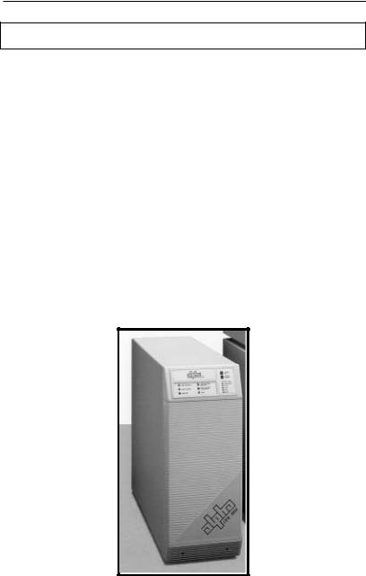
1.1 The Alpha CFR
Congratulations on your purchase of one of the most advanced and intelligent Controlled Ferroresonant-Uninterruptible Power Supplies (CFR-UPS) in the world! The Alpha CFR is designed to keep your equipment operating, regardless of the condition of your utility power. This means that your vital equipment will no longer be affected by spikes, surges, sags, noise, brownouts, blackouts or other forms of electrical disturbances. Operation is as simple as plugging your equipment into the back of the UPS and switching on the power.
The CFR provides you with a wide range of power management options using your choice of interface devices. The Standard Interface Device displays vital UPS operating parameters, including Alarms, and allows you to manually self-test the UPS.
The Intelligent Interface Device provides you with precise Voltage, Current and
Frequency information, plus maintains an on-going record of all Alarm and Line Failure Events. As an active center of communication, your CFR can also be interfaced directly to your computer system to inform you, and your users, of changes in status as they occur.
With distribution networks and service centers located throughout the world,
Alpha Technologies is here to back you up. From your date of purchase, Alpha provides complete technical support and prompt, reliable service to ensure that your
CFR-UPS provides you with a lifetime of reliable operation.
The Alpha CFR-UPS provides regulated, current-limited, output with excellent isolation and noise attenuation.
1

1.INTRODUCTION
1.2The CFR Advantage
ADVANCED POWER PROTECTION TECHNOLOGY
Power protection devices can be judged by the type and quality of power they provide. Alpha CFR Uninterruptible Power Supplies provide continuous, conditioned “computer-grade” AC power to electronic equipment such as Computer Systems, Point of Sale Terminals, Process Controls, Telecommunications, Cable TV Headend, Broadband LAN, Manufacturing Control Systems, Critical Care and Hospital Lab Equipment.
SURGE AND SPIKE REJECTION
Alpha's proven design virtually eliminates surges and spikes. The Alpha CFR UPS provides spike attenuation of 2000 to 1 and meets the requirements of IEEE 587 / ANSI 62.41.
REGULATION
Unlike many standby power systems which regulate output voltage only when operating from their battery backup, the Alpha CFR UPS
constantly maintains +1% output regulation without using precious battery power. Even with input voltage fluctuations as great as +10% or -25%, the output remains constant, regardless of load.
ISOLATION
Electromagnetic and Radio Frequency Interference (EMI and RFI) can damage semiconductors and have devastating effects on critical data. The CFR UPS input is totally isolated from the output to provide maximum protection from this type of interference. Measured in decibels (dB) of attenuation, Alpha's CFR achieves up to 120 dB common mode, and 60 dB normal mode.
EXTENDED BACKUP CAPABILITY
Alpha's EBP Series External Battery Packs allow you to greatly extend your backup capabilities and power through long utility outages. Completely self-contained and pre-wired, simply plug the EBP cabinet into your CFR and forget about it. EBP
Series External Battery Packs can also be ordered with an optional, external charger to greatly reduce battery recharge times.
2

1. INTRODUCTION
1.2 The CFR Advantage, continued
COMMUNICATIONS AND INTELLIGENCE
Alpha's interchangeable Standard Interface Device and Intelligent Interface
Device allow your CFR to become an active part of your communications network providing you with a variety of interface options.
SELF-TEST CAPABILITIES
The CFR has a built-in, self-test function that checks all critical areas of the
UPS, including the batteries, to ensure optimum performance. Whenever a problem is detected, the UPS lights a “Service” indicator. Self-test is extremely useful during troubleshooting and maintenance.
PRECISE LOAD & OVERLOAD INFORMATION
The Alpha CFR provides vital load information to eliminate guess work associated with matching the appropriate load to your unit. The Alpha CFR displays the existing load and, whenever the load exceeds the rated output, an "Overload" indicator is illuminated.
GENERATOR READY
The CFR UPS is equipped with a frequency sense circuit, along with a constant slew frequency synchronization circuit, to provide trouble-free operation with most standby generators.
SAFETY
Designed to meet or exceed the safety standards established by UL, CSA and VDE, the Alpha CFR UPS is one of the safest, most reliable and versatile uninterruptible power supplies available. Our commitment to safety and quality engineering has not only established industry-wide safety standards, but has earned Alpha Technologies international recognition as a leader in power protection equipment.
3
1. INTRODUCTION
1.3 Unpacking and Inspection
Carefully remove the UPS from its shipping container. Inspect the contents. If items appear to be damaged or missing, contact Alpha Technologies and the shipping company immediately. Most shipping companies have only a short claim period. Make sure the following items have been included:
1.CFR Series UPS with AC Line Cord
2.Operator's Manual
3.Any other ordered options
SAVE THE ORIGINAL SHIPPING CONTAINER.
In the event the UPS needs to be returned for service, it should be packaged in its original shipping container. If the original container is not available, make sure that the unit is packed with at least three inches of shock-absorbing material to prevent shipping damage. NOTE: Do not use popcorn-type material. Alpha Technologies is not responsible for damage caused by the improper packaging of returned units.
PLEASE READ THE OPERATOR'S MANUAL.
Become familiar with the UPS front and rear panels. Review the drawings and illustrations before proceeding with the UPS installation. If you have questions regarding the safe installation or operation of the UPS, contact Alpha Technologies.
COMPLETE THE FOLLOWING FOR YOUR RECORDS:
Model #
Serial #
Options
Purchase date
THIS UNIT WAS PURCHASED FROM:
Dealer name
City
State/Province
Zip/Postal Code
Country
Telephone #
4
2. FEATURES
2.1 A Tour of the CFR
The Alpha CFR is designed to be easy to use and extremely flexible. The CFR’s interchangeable front panel interface devices provide you with a wide range of information management options. The rear panel accepts a variety of connectors and receptacle plates to facilitate your most demanding communication and powering needs.
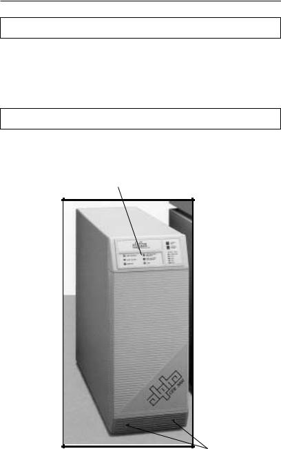
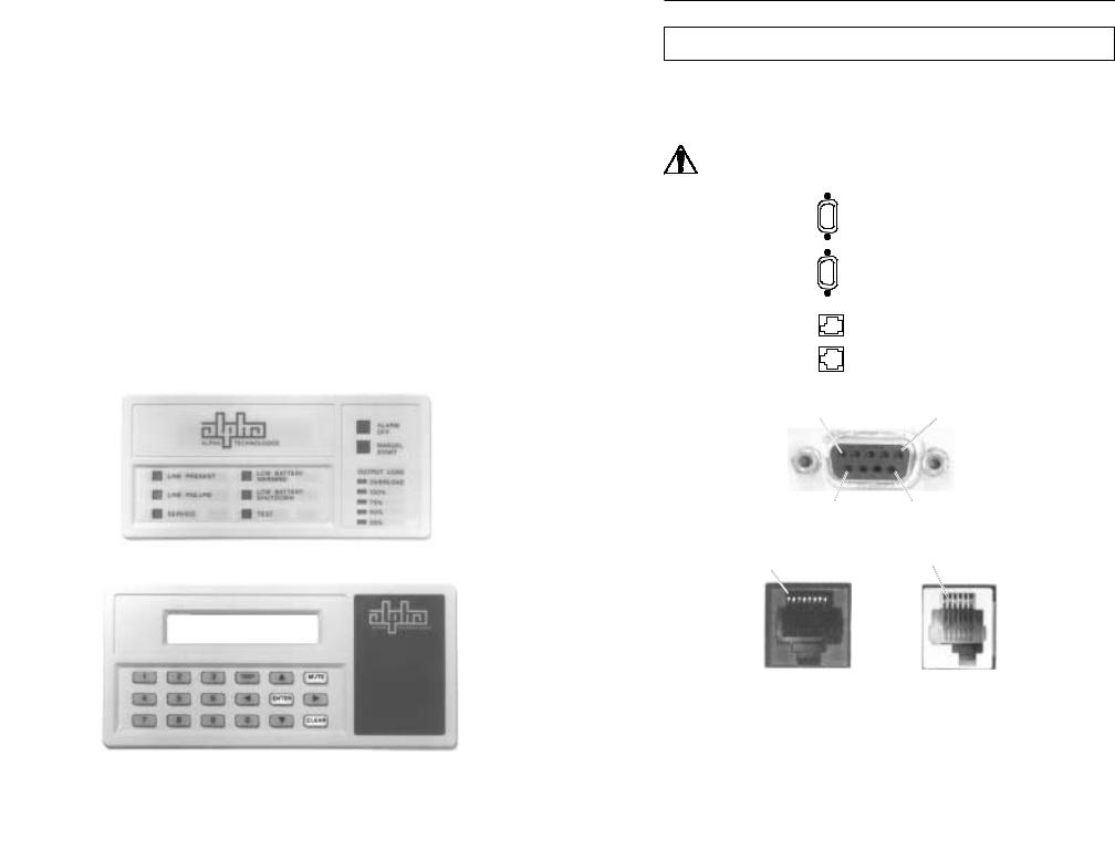
2.2 The CFR Front Panel
The CFR front panel comes equipped with a Standard Interface Device (SID), or an optional Intelligent Interface Device (IID), to display vital UPS operating parameters. The front panel can be easily removed for service or battery access by loosening the two screws located in the lower grill.
Standard Interface Device
Panel Screws
Fig.1
CFR Front Panel
5

2. FEATURES
2.3CFR Rear Panel
1.AC LINE Cord
The UPS is equipped with a standard, grounded AC line cord.
2.EXTERNAL BATTERY Connector
The connector accepts a standard plug from the EBP Series Battery Pack.
Extending backup time is as simple as plugging in the battery pack.
3. BATTERY Circuit Breaker
The battery breaker protects the DC circuit. When the UPS is not in service, the breaker should be switched OFF to preserve the batteries in the UPS and in the EBP
Series Battery Pack, if installed (see section 4.1 “UPS Shutdown”).
4.External Ground Lug (Single Point Ground)
The external ground lug provides a single point connection for optimum grounding
protection. Always refer to your local electrical codes for prescribed grounding practices.
5.UPS Nameplate Label
The nameplate label contains valuable information relating to the UPS. Always
verify input voltage and frequency (i.e., 120 VAC / 60 Hz) before use.
6.RS-232 Serial Connector (DE-9 Female Connector)*
The standard RS-232 serial interface allows for connection to a host computer/
dumb terminal for remote monitoring, control and calibration of the UPS. Use a straight through serial cable to connect the UPS to the computer.
7. LAN Interface Connector (DE-9 Female Connector)
The LAN Interface connector provides dry contact status monitoring and output shutdown capability on a DE-9 female connector and is used by basic UPS monitoring software for orderly shutdown of computer networks.
8.Modem Connection
Available as an option on 60Hz Models only.
9.External IID Connector (MMJ Connector)*
This connector is used for the optional desktop Intelligent Interface Device (IID) for
remote monitoring and control of the UPS (up to 2000 ft.).
NOTE: This port is disabled by the factory unless an internal IID is installed.
10.External Alarms Connector (RJ-45 Connector)
This provides dry contact closure alarm status on a RJ-45 (center keyed)
connector, indicating LINE FAIL and LOW BATTERY WARNING.
*NOTE: With the SID installed in the UPS, either the External IID port or the RS-232 port can be activated. The factory default is set for RS-232 operation. With the internal IID option installed in the UPS both ports are active.
6

2. FEATURES
2.3CFR Rear Panel
11.Exhaust Fan
The UPS contains a rear panel exhaust fan to ensure maximum cooling protection during all modes of operation.
12.OUTPUT Receptacle Plate
The load (equipment to be protected) connects to the rear panel output receptacles. Styles vary depending upon country, frequency and voltage.
13.AC OUTPUT Circuit Breaker
The resettable breaker provides addional output protection to the load.
8
7 |
|
|
|
9 |
|
|||
|
6 |
|
|
|
10 |
|
|
|
|
|
|
|
|
|
|
|
|
|
|
|
|
|
|
|
|
|
|
|
|
|
|
|
|
|
|
11
12
13
5
3
2
4
1
Fig. 2
CFR 1500, CFR 2000, CFR 2500, and CFR 3000 Rear Panel
7
2. FEATURES
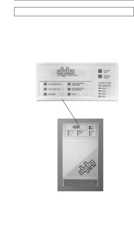
2.4 Information Management Options
Standard Interface Device
The Standard Interface Device provides you with vital UPS operating parameters from front panel LEDs (see section 4.2). The Standard Interface also has a load indicator to help you determine precise loading on your UPS, plus Manual Start and Alarm Off switches. To ensure optimum backup performance, the Standard Interface comes with a self-test feature which lights the “Service” LED whenever a problem is detected.
Fig. 3
CFR Front Panel with Standard Interface Device
8

2. FEATURES
2.4 Information Management Options, continued
Intelligent Interface Device (optional)
The Intelligent Interface Device (IID) option is available either as a replacement of the Standard Interface Device (SID) or as a desktop unit for remotely accessing the unit (up to 2000 ft.). The desktop unit comes with an optional modem for accessing the UPS information via a telephone line. The IID front panel provides precise UPS information and guides you through the various menu options which include Ambient Battery Temperature, Input Voltage and Current, Line Frequency, Output Voltage and Current, Power in Watts, Power Factor, Battery Voltage, Charger
Status, and more. The History Log maintains an on-going record of UPS alarms and power anomalies by time, date and type of occurrence. Whenever a UPS alarm condition occurs, such as Line Failure, Low Battery Warning, Low Battery Shutdown or Service, it is displayed by the front panel indicators and recorded in the History Log.
External Modem (option available on 60Hz models only)
The optional modem that comes with the desktop IID provides access to the unit via a phone line. Service personal can dial up the unit to remotely monitor, control, and calibrate the unit. On specified alarm conditions, the unit can dial an emergency number to notify the system manager via modem of the alarm. The modem option may also be used to page service personnel on critical alarm conditions.
For further information on operation and installation of the IID, please refer to its operator’s manual “Information Management Using the Intelligent Interface Device.”
Fig. 4
Intelligent Interface Device
9

2. FEATURES
2.5 Communication / Interface Options
The CFR is equipped with four rear panel jacks for communication and remote interfaces: RS-232 Serial data; LAN Interface; External IID and External Alarms.
Units with the external modem option have a fifth connector for modem connection.
NOTE: With the SID installed in the UPS, either the External IID port or the RS-232 port can be activated. The factory default is set for RS-232 operation. With the internal IID option installed in the UPS both ports are active.
RS-232 Monitoring / Control Applications
The Alpha CFR-UPS provides a standard RS-232 serial port on a DE-9 female connector. This port may be used to monitor and control the CFR using 1) ASCII terminals, 2) UPS monitoring software and 3) SNMP agent devices.
You may use the serial port to interface with a dumb terminal or a personal computer (running a terminal emulation software) to monitor, control, and calibrate the CFR. All you need is a standard off-the-shelf RS-232 cable (straight through) and a terminal. Refer to section 5 “RS-232 TERMINAL COMMUNICATION” for more information.
You may also use the RS-232 serial port to communicate with the intelligent UPS monitoring software running on a host computer or a SNMP agent device connected to your LAN network. Alpha Technologies provides the “AlphaNet C” family of UPS monitoring software and SNMP agents to manage your network requirements. You can use the “AlphaNet C shutdown software” to monitor the
CFR in a network environment and to perform an orderly system shutdown when the battery becomes low (during extended line fail situations). AlphaNet C shutdown software informs all workstations of pending power failures and shutdowns and in multi-server networks, AlphaNet can shutdown other servers in the network as well as the workstations. For a full description of the features and capabilities of AlphaNet C shutdown software, refer to its user’s manual or contact Alpha Technologies. AlphaNet C is available for all major network platforms and operating systems — Novell Netware, SCO Unix, IBM OS/2, IBM AIX, Sun Solaris,
Hewlett-Packard HP-UX (DAT), and Digital Equipment (OS/F, VMS, and DECNET).
Alpha Technologies also provides the “AlphaNet CS SNMP Agent Device” to monitor and control the CFR using the SNMP protocol. This provides an interface between the CFR and your network environment and allows you to use your
Network Management Station (NMS) to monitor and control the CFR. To obtain detailed information on SNMP management solutions for your CFR refer to
AlphaNet CS SNMP Agent User’s Manual or contact Alpha Technologies.
10
2. FEATURES
2.5 Communication / Interface Options, continued
Rear Panel Connectors:
Below are the various communication connectors as they appear on the back of the CFR-UPS. The photographs show the pin numbering for the different connector types.
NOTE: Use only fully shielded cables to make connections to any of the
DE-9 connectors (RS-232 port or LAN interface).
RS-232 Serial Connector
LAN Interface Connector
External IID Connector
External Alarms Connector
Pin 5 |
Pin 1 |
Pin 6 |
Pin 9 |
DE-9 Connector (RS-232 and LAN)
Pin 1 |
Pin 1 |
RJ-45 |
MMJ |
(External Alarms) |
(External IID) |
Fig. 5
CFR-UPS Connector Identification and Pin-out
11
2. FEATURES
2.5 Communication / Interface Options, continued
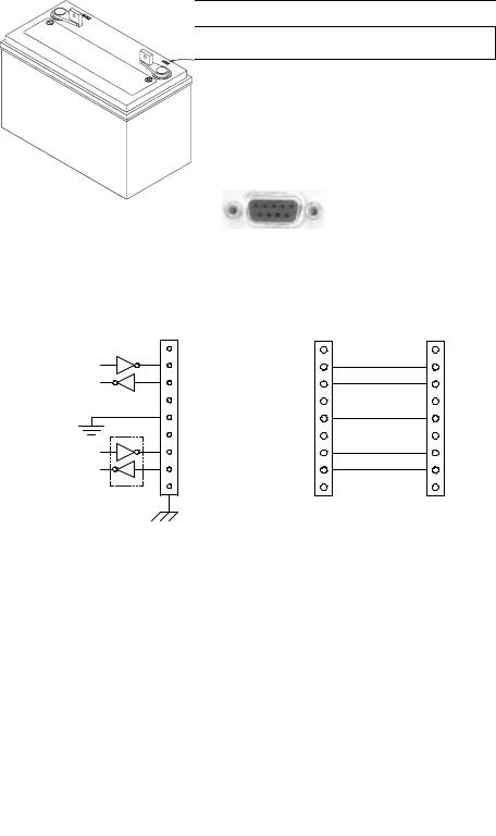
RS-232 Connector:
The connection/specifications for the RS-232 serial port vary depending on the installed interface device (i.e., SID or IID option).
RS-232 connection for the standard CFR-UPS (with SID or internal IID display)
The standard CFR-UPS configuration with SID or internal IID connects to a computer or terminal using a standard straight-through RS-232 cable.
Fig. 6
CFR-UPS RS-232 Connector
1 |
|
1 |
1 |
2 |
Tx |
2 |
2 |
3 |
Rx |
3 |
3 |
4 |
|
4 |
4 |
5 |
Gnd |
5 |
5 |
6 |
|
6 |
6 |
7 |
RTS* |
7 |
7 |
8CTS* |
8 |
8 |
|
9 |
|
9 |
9 |
Internal CFR connections |
RS-232 cable to computer or terminal |
||
*IID Only (Not used with SID) |
Use standard straight through type |
||
Communication Settings with IID: |
Communication Settings with SID: |
||
Baud Rate: |
300 to 9600 |
Baud Rate: |
1200 |
Parity: |
None, Even, or Odd |
Parity: |
None |
Stop Bits: |
1 or 2 |
Stop Bits: |
One |
Data Bits: |
7 or 8 |
Data Bits: |
8 |
Handshaking: |
RTS/CTS |
Handshaking: |
XON / OFF |
12
2. FEATURES
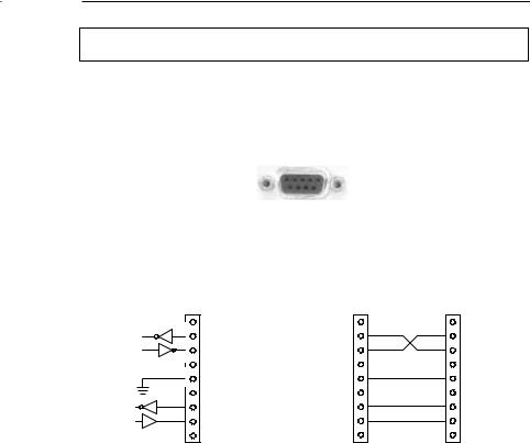
2.5 Communication / Interface Options, continued
RS-232 Connections with desktop IID:
With the desktop IID the cable connecting the computer or terminal to the UPS is a nonstandard type.
Fig. 7
CFR-UPS RS-232 Connector
1 |
|
1 |
1 |
2 |
Tx |
2 |
2 |
3 |
Rx |
3 |
3 |
4 |
|
4 |
4 |
5 Gnd |
5 |
5 |
|
6 |
|
6 |
6 |
7 |
RTS |
7 |
7 |
8 |
CTS |
8 |
8 |
9 |
|
9 |
9 |
Internal CFR connections |
RS-232 cable to |
|
computer or terminal |
|
For the desktop IID use a |
|
nonstandard cable type |
Communication Settings with IID: |
|
Baud Rate: |
300 to 9600 |
Parity: |
None, Even, or Odd |
Stop Bits: |
1 or 2 |
Data Bits: |
7 or 8 |
Handshaking: |
RTS/CTS |
13
2. FEATURES
2.5 Communication / Interface Options, continued
LAN Interface Connector
The Alpha CFR-UPS provides a LAN interface port on a DE-9 female connector. This port may be used to monitor the status of the UPS and shutdown the output using basic UPS monitoring and shutdown software.
Two dry contacts are provided to indicate LINE FAIL and LOW BATTERY status information. The port also accepts a dry contact input or an RS-232 level input to shutdown the UPS output. The shutdown delay, duration, and recovery modes can be configured using the RS-232 ASCII terminal commands (see section 5 “RS-232 Terminal Communication”). This port has the following pin out:
1
2 LINE FAIL
3
4 COMMON
5 LOW BATTERY
6 OUTPUT SHUTDOWN
7 GND
8 +12VDC, 5mA max.
9
Fig. 8
Pin out: (DE-9 connector), Female
Using basic UPS monitoring software you can monitor and shutdown the CFR through this port. In network applications, your UPS monitoring software can perform an orderly shutdown on the network. Basic UPS monitoring software is provided as part of many operating systems and can also be purchased from third party vendors. Alpha Technologies “AlphaNet C shutdown software” can also operate in the basic mode to shutdown the CFR before its battery reserve is exhausted. Refer to
AlphaNet C Shutdown Software User’s Manual or contact Alpha Technologies for more information.
14

2. FEATURES
2.5 Communication / Interface Options, continued
External IID Connector
The external IID connector provides an interface for the optional desktop Intelligent Interface Device (IID). This allows the CFR to be remotely monitored and controlled from up to 2,000 feet away. The port uses a proprietary RS-485 protocol and has the following pin out:
Pin 1
1: +12V DC (unreg) |
4: RS-485 Negative |
2: +12V DC (unreg) |
5: GND |
3: RS-485 Positive |
6: GND |
Fig. 9
Pin out: (MMJ connector, offset key)
Modem (optional configuration with Intelligent Interface Device; available on 60 Hz models only)
When the CFR UPS is equipped with an Intelligent Interface Device (IID), an internal modem can be installed to provide long-range communications. A standard modular telephone cable is used to connect the CFR modem jack to the wall jack.
For further information, refer to the Intelligent Interface Device manual.
External Alarms Connector
The external alarms connector provides two contact closures to indicate LINE FAIL and LOW BATTERY alarms.
EPO (Emergency Power OFF) Switch (Factory Installed Option)
Pins 7 and 8 of the ALARM INTERFACE connector provide EMERGENCY POWER OFF contacts. A switch contact can be hard-wired to the UPS to completely shut down the system in the event of an emergency, such as a fire.
In an emergency, the switch must be depressed (shorted) for at least 1.5 seconds. The UPS will shut down approximately 2 seconds after the signal is recognized. The switch, connected to pins 7 and 8, must be electrically isolated (up to 1500 VAC isolation is recommended). A system shut down in this manner will open the BATTERY circuit breaker.
CAUTION: When the EPO switch is activated, the AC line connected to the
UPS input may still be energized. To completely remove the power from the building, the MAIN AC line breaker in the building must be switched OFF. Consult your national and local electrical codes for further information.
15

2. FEATURES
2.5 Communication / Interface Options, continued
External Alarms Connector, continued
Pin out: (RJ-45 connector, centered key)
Pin 1
Low Battery
Warning
Line Present
Line Failure |
N.C. |
N.C. |
|
|
Battery OK |
|
|
N.C. = Normally Closed |
EPO |
|
Emergency |
||
N.O. = Normally Open |
||
Power OFF |
||
|
Option
Pin out: (RJ-45 connector, Female)
1.LINE FAIL, COM contact
2.LINE FAIL, N. C. contact
3.LINE FAIL, N. O. contact
4.LOW BATTERY, N. O. contacts
5.LOW BATTERY, COM contacts
6.LOW BATTERY, N. C. contacts
N.O.
Emergency UPS Shutdown Switch (Wall Mounted). NOTE: Cable length must not exceed 100 feet. Use twisted or shielded wire.
External Alarms Connector Pin-out (with factory installed EPO Switch Option)
16
Loading...