


 Allison


 4
4

 th Generation

 Controls


Troubleshooting

Manual
1000 and 2000 Product Families
TS3977EN

Troubleshooting |
1000 AND 2000 PRODUCT FAMILIES |
|
Manual |
|
ALLISON 4TH GENERATION CONTROLS |
TS3977EN |
200707 |
|

Troubleshooting
Manual
2007 FEBRUARY
REV. 1 2007 JULY
TS3977EN
Allison Transmission
ALLISON 4TH GENERATION CONTROLS
1000 and 2000 Product Families
Allison Transmission, Inc.
P.O. Box 894 Indianapolis, Indiana 46206-0894
www.allisontransmission.com
Printed in USA |
Copyright © 2007 Allison Transmission, Inc. |

1000 AND 2000 PRODUCT FAMILIES TROUBLESHOOTING MANUAL—ALLISON 4th GENERATION CONTROLS
FOREWORD — How to Use This Manual
This manual provides troubleshooting information for Allison Transmission 1000 and 2000 Product Families transmissions. Service Manual SM4006EN, Mechanics Tips MT4007EN, and Parts Catalog PC3062EN may be used in conjunction with this manual.
This manual includes:
•Description of the electronic control system.
•Description of the electronic control system components.
•Description of diagnostic codes, system responses to faults, and troubleshooting.
•Wire, terminal, and connector repair information.
Specific instructions for using many of the available or required service tools and equipment are not included in this manual. The service tool manufacturer will furnish instructions for using the tools or equipment.
Additional information may be published from time to time in Service Information Letters (SIL) and will be included in future revisions of this and other manuals. Please use these SILs to obtain up-to-date information concerning Allison Transmission products.
This publication is revised periodically to include improvements, new models, special tools, and procedures. A revision is indicated by a new date on the title page and rear cover. Check with your Allison Transmission service outlet for the currently applicable publication. Additional copies of this publication may be purchased from authorized Allison Transmission service outlets. Look in your telephone directory under the heading of Transmissions—Truck, Tractor, etc.
Take time to review the Table of Contents and the manual. Reviewing the Table of Contents will aid you in quickly locating information.
NOTE: Allison Transmission is providing service of wiring harnesses and wiring harness components as follows:
•Repair parts for the internal wiring harness will be available through the Allison Transmission Parts Distribution Center (PDC). Use the P/N from your appropriate parts catalog or from Appendix E in this manual. Allison Transmission is responsible for warranty on these parts.
•Repair parts for the external harnesses and external harness components must be obtained from the vehicle OEM or the OEM is responsible for warranty on these parts.
ii |
Copyright© 2007 Allison Transmission, Inc. |

1000 AND 2000 PRODUCT FAMILIES TROUBLESHOOTING MANUAL—ALLISON 4th GENERATION CONTROLS
IMPORTANT SAFETY NOTICE
IT IS YOUR RESPONSIBILITY to be completely familiar with the warnings and cautions used in this manual. These warnings and cautions advise against using specific service procedures that can result in personal injury, equipment damage, or cause the equipment to become unsafe. These warnings and cautions are not exhaustive. Allison Transmission could not possibly know, evaluate, or advise the service trade of all conceivable procedures by which service might be performed or of the possible hazardous consequences of each procedure. Consequently, Allison Transmission has not undertaken any such broad evaluation. Accordingly, ANYONE WHO USES A SERVICE PROCEDURE OR TOOL WHICH IS NOT RECOMMENDED BY ALLISON TRANSMISSION MUST first be thoroughly satisfied that neither personal safety nor equipment safety will be jeopardized by the service procedures used.
Also, be sure to review and observe WARNINGS, CAUTIONS, and NOTES provided by the vehicle manufacturer and/or body builder before servicing the Allison transmission in that vehicle.
Proper service and repair is important to the safe and reliable operation of the equipment. The service procedures recommended by Allison Transmission and described in this manual are effective methods for performing troubleshooting operations. Some procedures require using specially designed tools. Use special tools when and in the manner recommended.
The WARNINGS, CAUTIONS, and NOTES in this manual apply only to the Allison transmission and not to other vehicle systems which may interact with the transmission. Be sure to review and observe any vehicle system information provided by the vehicle manufacturer and/or body builder at all times the Allison transmission is being serviced.
WARNINGS, CAUTIONS, AND NOTES
Three types of headings are used in this manual to attract your attention:
WARNING! Is used when an operating procedure, practice, etc., which, if not correctly followed, could result in injury or loss of life.
CAUTION: |
Is used when an operating procedure, practice, etc., which, if not strictly observed, |
|
could result in damage to or destruction of equipment. |
||
|
||
|
|
NOTE: Is used when an operating procedure, practice, etc., is essential to highlight.
Copyright© 2007 Allison Transmission, Inc. |
iii |

1000 AND 2000 PRODUCT FAMILIES TROUBLESHOOTING MANUAL—ALLISON 4th GENERATION CONTROLS
TRADEMARKS USED IN THIS MANUAL
The following trademarks are the property of the companies indicated:
•Adobe® Acrobat® Reader® are registered trademarks of Adobe Systems Incorporated.
•Allison DOC™ For PC—Service Tool is a trademark of General Motors Corporation.
•LPS® Cleaner is a registered trademark of LPS Laboratories.
•Loctite® is a registered trademark of the Loctite Corporation.
•Teflon® is a registered trademark of the DuPont Corporation.
•Windows® 95, Windows® 98, Windows® XP, and Windows NT® are trademarks of Microsoft Corporation.
SERVICE LITERATURE
This service literature provides fully illustrated instructions for operation, maintenance, service, overhaul, and parts support for your transmission. For maximum performance and service life from you unit, you may order publications from:
SGI, Inc.
Attn: Allison Literature Fulfillment Desk
8350 Allison Avenue
Indianapolis, IN 46268
TOLL FREE: 888-666-5799
INTERNATIONAL: 317-471-4995
1000 and 2000 Product Families Service Literature
Publication Name |
Publication No. |
|
|
Allison DOC™ For PC–Service Tool User Guide |
GN3433EN |
|
|
Automatic Transmission Fluid Technician’s Guide |
GN2055EN |
|
|
*Mechanic’s Tips |
MT4007EN |
|
|
*In-Chassis Maintenance |
GN4008EN |
|
|
*Emergency Vehicle Series Operator’s Manual |
OM3761EN |
|
|
*Highway Series Operator’s Manual |
OM3757EN |
|
|
*Rugged Duty Series Operator’s Manual |
OM3759EN |
|
|
*Motorhome Series Operator’s Manual |
OM3364EN |
|
|
*Pupil Transport/Shuttle Series Operator’s Manual |
OM3758EN |
|
|
*Bus Series Operator’s Manual |
OM3765EN |
|
|
*1000, 2000, 2400 Operator’s Manual |
OM3063EN |
|
|
*Owner’s Manual (2000MH) |
OM3364EN |
|
|
*Parts Catalog |
PC3062EN |
|
|
Parts Catalog On CD-ROM |
CD3062EN |
|
|
Principles Of Operation |
PO4009EN |
|
|
Service Manual |
SM4006EN |
|
|
Troubleshooting Manual—Allison 4th Generation Controls |
TS3977EN |
* Also Available On The Internet At www.allisontransmission.com |
|
|
|
iv |
Copyright© 2007 Allison Transmission, Inc. |

1000 AND 2000 PRODUCT FAMILIES TROUBLESHOOTING MANUAL—ALLISON 4th GENERATION CONTROLS
TABLE OF CONTENTS
Page
Foreword . . . . . . . . . . . . . . . . . . . . . . . . . . . . . . . . . . . . . . . . . . . . . . . . . . . . . . . . . . . . . . . . . . . . . . . . . . . . .ii
SAFETY INFORMATION
Important Safety Notice . . . . . . . . . . . . . . . . . . . . . . . . . . . . . . . . . . . . . . . . . . . . . . . . . . . . . . . . . . . . iii Warnings, Cautions, and Notes . . . . . . . . . . . . . . . . . . . . . . . . . . . . . . . . . . . . . . . . . . . . . . . . . . . . . . iii Trademarks Used in This Manual . . . . . . . . . . . . . . . . . . . . . . . . . . . . . . . . . . . . . . . . . . . . . . . . . . . . iv Service Literature. . . . . . . . . . . . . . . . . . . . . . . . . . . . . . . . . . . . . . . . . . . . . . . . . . . . . . . . . . . . . . . . . iv
SECTION 1. GENERAL DESCRIPTION
1–1. TRANSMISSION . . . . . . . . . . . . . . . . . . . . . . . . . . . . . . . . . . . . . . . . . . . . . . . . . . . . . . . . . . . . . . .1–1
1–2. TRANSMISSION CONTROL MODULE (TCM) . . . . . . . . . . . . . . . . . . . . . . . . . . . . . . . . . . . . . .1–3
1–3. SHIFT SELECTOR . . . . . . . . . . . . . . . . . . . . . . . . . . . . . . . . . . . . . . . . . . . . . . . . . . . . . . . . . . . . . .1–3
A. Shift Selector Range Positions . . . . . . . . . . . . . . . . . . . . . . . . . . . . . . . . . . . . . . . . . . . . . . . . . . .1–3
B. Manual Selector Valve . . . . . . . . . . . . . . . . . . . . . . . . . . . . . . . . . . . . . . . . . . . . . . . . . . . . . . . . .1–4
C. Internal Mode Switch (IMS). . . . . . . . . . . . . . . . . . . . . . . . . . . . . . . . . . . . . . . . . . . . . . . . . . . . .1–5
1–4. THROTTLE POSITION SENSOR (TPS) . . . . . . . . . . . . . . . . . . . . . . . . . . . . . . . . . . . . . . . . . . . . .1–5
1–5. SPEED SENSORS. . . . . . . . . . . . . . . . . . . . . . . . . . . . . . . . . . . . . . . . . . . . . . . . . . . . . . . . . . . . . . .1–6
A. Input (Engine) Speed Sensor . . . . . . . . . . . . . . . . . . . . . . . . . . . . . . . . . . . . . . . . . . . . . . . . . . . .1–6
B. Turbine Speed Sensor . . . . . . . . . . . . . . . . . . . . . . . . . . . . . . . . . . . . . . . . . . . . . . . . . . . . . . . . . .1–6
C. Output Speed Sensor. . . . . . . . . . . . . . . . . . . . . . . . . . . . . . . . . . . . . . . . . . . . . . . . . . . . . . . . . . .1–7
1–6. CONTROL VALVE ASSEMBLY . . . . . . . . . . . . . . . . . . . . . . . . . . . . . . . . . . . . . . . . . . . . . . . . . . .1–7
A. Main Modulation . . . . . . . . . . . . . . . . . . . . . . . . . . . . . . . . . . . . . . . . . . . . . . . . . . . . . . . . . . . . .1–8
1–7. WIRING HARNESSES. . . . . . . . . . . . . . . . . . . . . . . . . . . . . . . . . . . . . . . . . . . . . . . . . . . . . . . . . . .1–8
A. External Wiring Harness. . . . . . . . . . . . . . . . . . . . . . . . . . . . . . . . . . . . . . . . . . . . . . . . . . . . . . . .1–8
B. Internal Wiring Harness . . . . . . . . . . . . . . . . . . . . . . . . . . . . . . . . . . . . . . . . . . . . . . . . . . . . . . .1–10
1–8. SPECIAL ELECTRONIC/ELECTRICAL TOOLS . . . . . . . . . . . . . . . . . . . . . . . . . . . . . . . . . . . .1–11
SECTION 2. DEFINITIONS AND ABBREVIATIONS
2–1. CHECK TRANS LIGHT . . . . . . . . . . . . . . . . . . . . . . . . . . . . . . . . . . . . . . . . . . . . . . . . . . . . . . . . . .2–1 2–2. RANGE INHIBIT RESPONSES. . . . . . . . . . . . . . . . . . . . . . . . . . . . . . . . . . . . . . . . . . . . . . . . . . . .2–1 2–3. ALLISON DOC™ FOR PC–SERVICE TOOL INHIBITS. . . . . . . . . . . . . . . . . . . . . . . . . . . . . . . .2–1 2–4. ALLISON DOC™ FOR PC–SERVICE TOOL. . . . . . . . . . . . . . . . . . . . . . . . . . . . . . . . . . . . . . . . .2–4 2–5. ABBREVIATIONS . . . . . . . . . . . . . . . . . . . . . . . . . . . . . . . . . . . . . . . . . . . . . . . . . . . . . . . . . . . . . .2–5
SECTION 3. BASIC KNOWLEDGE
3–1. BASIC KNOWLEDGE REQUIRED . . . . . . . . . . . . . . . . . . . . . . . . . . . . . . . . . . . . . . . . . . . . . . . .3–1 3–2. USING THE TROUBLESHOOTING MANUAL. . . . . . . . . . . . . . . . . . . . . . . . . . . . . . . . . . . . . . .3–1 3–3. SYSTEM OVERVIEW . . . . . . . . . . . . . . . . . . . . . . . . . . . . . . . . . . . . . . . . . . . . . . . . . . . . . . . . . . .3–1 3–4. IMPORTANT INFORMATION IN THE TROUBLESHOOTING PROCESS. . . . . . . . . . . . . . . . .3–2 3–5. BASIC TROUBLESHOOTING INFORMATION . . . . . . . . . . . . . . . . . . . . . . . . . . . . . . . . . . . . . .3–3 3–6. TCM DIAGNOSTIC PROCEDURE . . . . . . . . . . . . . . . . . . . . . . . . . . . . . . . . . . . . . . . . . . . . . . . . .3–9 3–7. RESETTING OF TCM PARAMETERS TO SUPPORT ENGINE UPDATE. . . . . . . . . . . . . . . . . .3–9 3–8. RESETTING TCM SEM AUTOSELECT. . . . . . . . . . . . . . . . . . . . . . . . . . . . . . . . . . . . . . . . . . . .3–10
Copyright© 2007 Allison Transmission, Inc. |
v |

1000 AND 2000 PRODUCT FAMILIES TROUBLESHOOTING MANUAL—ALLISON 4th GENERATION CONTROLS
TABLE OF CONTENTS (cont’d)
Page
SECTION 4. WIRE CHECK PROCEDURES
4–1. CHECKING OPENS, SHORTS BETWEEN WIRES, AND SHORTS-TO-GROUND . . . . . . . . . 4–1
4–2. CHECKING AT TRANSMISSION CONNECTOR AND THE INTERNAL HARNESS
FOR OPENS, SHORTS BETWEEN WIRES, AND SHORTS-TO-GROUND. . . . . . . . . . . . . . . . 4–2
SECTION 5. DIAGNOSTIC TROUBLE CODES (DTC)
5–1. DTC MEMORY . . . . . . . . . . . . . . . . . . . . . . . . . . . . . . . . . . . . . . . . . . . . . . . . . . . . . . . . . . . . . . . . 5–1
5–2. FAILURE RECORDS . . . . . . . . . . . . . . . . . . . . . . . . . . . . . . . . . . . . . . . . . . . . . . . . . . . . . . . . . . . 5–1
5–3. DTC READING AND DTC CLEARING . . . . . . . . . . . . . . . . . . . . . . . . . . . . . . . . . . . . . . . . . . . . 5–3
A. Clearing DTCs. . . . . . . . . . . . . . . . . . . . . . . . . . . . . . . . . . . . . . . . . . . . . . . . . . . . . . . . . . . . . . . 5–3
B. Clearing Active Indicators. . . . . . . . . . . . . . . . . . . . . . . . . . . . . . . . . . . . . . . . . . . . . . . . . . . . . . 5–3
5–4. BEGINNING THE TROUBLESHOOTING PROCESS . . . . . . . . . . . . . . . . . . . . . . . . . . . . . . . . . 5–3
A. Starting Procedure . . . . . . . . . . . . . . . . . . . . . . . . . . . . . . . . . . . . . . . . . . . . . . . . . . . . . . . . . . . . 5–3
B. Solenoid Locations . . . . . . . . . . . . . . . . . . . . . . . . . . . . . . . . . . . . . . . . . . . . . . . . . . . . . . . . . . . 5–4
C. Wire/Terminal Numbering Scheme. . . . . . . . . . . . . . . . . . . . . . . . . . . . . . . . . . . . . . . . . . . . . . . 5–4
D. Available Diagnostic Adapters . . . . . . . . . . . . . . . . . . . . . . . . . . . . . . . . . . . . . . . . . . . . . . . . . . 5–4
5–5. DIAGNOSTIC TROUBLE CODES (DTCs—Includes Index) . . . . . . . . . . . . . . . . . . . . . . . . . . . 5–10
SECTION 6. INPUT AND OUTPUT FUNCTIONS
6–1. SPECIAL INPUT AND OUTPUT FUNCTIONS . . . . . . . . . . . . . . . . . . . . . . . . . . . . . . . . . . . . . . 6–1
A. Input Functions . . . . . . . . . . . . . . . . . . . . . . . . . . . . . . . . . . . . . . . . . . . . . . . . . . . . . . . . . . . . . . 6–1
B. Output Functions . . . . . . . . . . . . . . . . . . . . . . . . . . . . . . . . . . . . . . . . . . . . . . . . . . . . . . . . . . . . . 6–1
SECTION 7. GENERAL TROUBLESHOOTING OF PERFORMANCE COMPLAINTS . . . . . . . . . . 7–1
APPENDICES
A. DIAGNOSING INTERMITTENT DTCs . . . . . . . . . . . . . . . . . . . . . . . . . . . . . . . . . . . . . . . . . . . . A–1 B. MAIN PRESSURE CHECK PROCEDURE . . . . . . . . . . . . . . . . . . . . . . . . . . . . . . . . . . . . . . . . . . B–1 C. SOLENOID AND CLUTCH TABLE . . . . . . . . . . . . . . . . . . . . . . . . . . . . . . . . . . . . . . . . . . . . . . . C–1 D. WIRE/CONNECTOR TABLES. . . . . . . . . . . . . . . . . . . . . . . . . . . . . . . . . . . . . . . . . . . . . . . . . . . . D–1 E. CONNECTOR REPAIR INFORMATION . . . . . . . . . . . . . . . . . . . . . . . . . . . . . . . . . . . . . . . . . . . E–1 F. THROTTLE POSITION SENSOR ADJUSTMENT . . . . . . . . . . . . . . . . . . . . . . . . . . . . . . . . . . . . F–1 G. WELDING ON VEHICLE/VEHICLE INTERFACE MODULE . . . . . . . . . . . . . . . . . . . . . . . . . . G–1 H. HYDRAULIC SCHEMATICS . . . . . . . . . . . . . . . . . . . . . . . . . . . . . . . . . . . . . . . . . . . . . . . . . . . . . H–1 J. WIRING SCHEMATIC . . . . . . . . . . . . . . . . . . . . . . . . . . . . . . . . . . . . . . . . . . . . . . . . . . . . . . . . . . .J–1 K. RESISTANCE vs. TEMPERATURE . . . . . . . . . . . . . . . . . . . . . . . . . . . . . . . . . . . . . . . . . . . . . . . . K–1 L. ELECTRONIC INTERFERENCE. . . . . . . . . . . . . . . . . . . . . . . . . . . . . . . . . . . . . . . . . . . . . . . . . . L–1 M. Allison DOC™ FOR PC–SERVICE TOOL. . . . . . . . . . . . . . . . . . . . . . . . . . . . . . . . . . . . . . . . . . .M–1 N. INPUT/OUTPUT FUNCTIONS . . . . . . . . . . . . . . . . . . . . . . . . . . . . . . . . . . . . . . . . . . . . . . . . . . . N–1 P. J1939 AND J2284 HARDWARE AND TCM CONNECTIONS. . . . . . . . . . . . . . . . . . . . . . . . . . . P–1 R. FLUID CHECK PROCEDURE . . . . . . . . . . . . . . . . . . . . . . . . . . . . . . . . . . . . . . . . . . . . . . . . . . . . R–1
vi |
Copyright© 2007 Allison Transmission, Inc. |
1000 AND 2000 PRODUCT FAMILIES TROUBLESHOOTING MANUAL—ALLISON 4th GENERATION CONTROLS
SECTION 1—GENERAL DESCRIPTION
1–1. TRANSMISSION
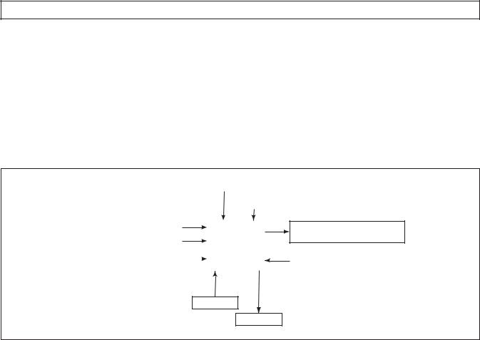
The 1000 and 2000 Product Families Allison 4th Generation Controls system features closed-loop clutch control to provide superior shift quality over a wide range of operating conditions. The 1000 and 2000 Product Families configurations can be programmed to provide up to six forward speeds, neutral, and reverse. The fifth and sixth ranges are overdrive gear ratios. The 1000 and 2000 Product Families incorporates a variety of standard and optional design features.
Figure 1–1 is a block diagram of the basic system inputs and outputs.
|
|
PRESSURE SWITCH MANIFOLD |
|
|
|||||
|
|
|
|
|
|
|
|
|
|
|
|
|
|
|
|
|
|
|
|
|
|
|
|
|
|
INTERNAL MODE SWITCH |
|
||
|
|
|
|
|
|
|
|
|
|
|
|
|
|
|
|
|
|
|
|
|
SPEED SENSORS |
|
|
|
|
|
SOLENOIDS |
||
|
|
|
|
|
|
|
|
(VBS, ON/OFF) |
|
THROTTLE POSITION SENSOR |
|
|
TCM |
|
|||||
|
|
|
|
|
|||||
|
|
|
|
|
|
|
|
||
|
VEHICLE/ENGINE |
|
|
|
|
|
TEMPERATURE SENSOR |
||
|
COMMUNICATION LINKS |
|
|
|
|
|
(SUMP/ENGINE) |
||
INPUTS
OUTPUTS
V05726.00.01
Figure 1–1. Transmission Control Module Block Diagram
Figure 1–2 shows the electronic control components.
Electronic Controls consist of the following elements:
•Remote 12V or 24V Transmission Control Module (TCM)
•Throttle Position Sensor (TPS), electronic engine throttle data, or PWM signal
•Speed Sensors—Input (Engine), Turbine, and Output
•Control Valve Assembly (Electro-Hydraulic Valve Body)
•Internal Mode Switch (IMS)
•Pressure Switch Manifold (PSM)
•Wiring Harnesses
NOTE: All external harnesses are OEM-supplied.
Copyright© 2007 Allison Transmission, Inc. |
1–1 |

1000 AND 2000 PRODUCT FAMILIES TROUBLESHOOTING MANUAL—ALLISON 4th GENERATION CONTROLS
GENERAL DESCRIPTION
TRANSMISSION
CONTROL
MODULE (TCM)
TRANSMISSION
HARNESS
80-WAY CONNECTOR
J1939
CONNECTOR
OEM SUPPLIED
INTERFACE HARNESS
ENGINE
SPEED SENSOR
CONNECTOR
OUTPUT
SPEED SENSOR
 CONNECTOR
TURBINE
SPEED SENSOR
CONNECTOR
THROTTLE POSITION SENSOR (TPS) CONNECTOR (OPTIONAL)
THROTTLE
POSITION
SENSOR (TPS)
24-WAY MAIN |
20-WAY |
TRANSMISSION |
CONNECTOR |
CONNECTOR |
(OPTIONAL) |
NOTE: Illustration is not to scale. Actual harness configuration may differ from this illustration.
V06475.03.00
.
Figure 1–2. Electronic Control Components
1–2 |
Copyright© 2007 Allison Transmission, Inc. |
1000 AND 2000 PRODUCT FAMILIES TROUBLESHOOTING MANUAL—ALLISON 4th GENERATION CONTROLS
GENERAL DESCRIPTION
1–2. TRANSMISSION CONTROL MODULE (TCM)
The electronic control of the transmission is performed by a microcomputer. The microcomputer is an independent controller and is referred to as a Transmission Control Module (TCM). TCMs are available in both 12V and 24V configurations to match the configuration of the vehicle electrical system.
The TCM (refer to Figure 1–3) receives and processes signals from various switches and sensors. The TCM determines shift sequences, shift timing, and clutch apply and release pressures. The TCM uses the information to control transmission solenoids and valves, supply system status, and provide diagnostic information.
V09005.00.00
Figure 1–3. Transmission Control Module (TCM)
1–3. SHIFT SELECTOR
The vehicle is equipped with a lever-type shift selector (refer to Figure 1–4). In addition to the lever assembly provided for the operator, other components associated with the shift selector are the manual selector valve in the main control valve body and an Internal Mode Switch (IMS) mounted on the selector shaft inside the transmission oil pan. Shift selector components (with the exception of the transmission selector shaft) are customer-supplied.
A.Shift Selector Range Positions
The operator chooses the transmission range by moving the selector lever to the appropriate gate position (refer to Figure 1–4). When properly adjusted, the shifter gates prevent inadvertent shifting between ranges and correspond to the internal transmission detent positions. A positive detent is provided in the transmission to maintain the selector shaft in the selected position.
Copyright© 2007 Allison Transmission, Inc. |
1–3 |

1000 AND 2000 PRODUCT FAMILIES TROUBLESHOOTING MANUAL—ALLISON 4th GENERATION CONTROLS
GENERAL DESCRIPTION
 SHIFT SELECTOR
P
R
N
OD
D 2 1
TOP VIEW
V06476.01.00
Figure 1–4. Typical Lever-Type Shift Selector
The TCM shift calibration determines the available forward ranges for each selector position. Although specific installations vary, typical selector positions for the 1000 and 2000 Product Families are:
P—Park. Parking pawl or parking brake is engaged, if available. This position is not available on all shift selectors.
R—Reverse.
N—Neutral. May be used when starting the engine and for stationary operations.
OD—Overdrive. The highest forward range used for normal driving. The transmission shifts to first range for starting, then automatically upshifts through the ranges (as operating conditions permit) until the highest range is attained.
D, 2, 1—Forward Range. The transmission shifts to first range for starting. The range selected on the shift selector is the highest range which will be attained during automatic shifting (on GM truck applications, a position M is used for Tap Up/Tap Down functionality).
B.Manual Selector Valve
The manual shift selector shaft is attached to the manual selector valve within the transmission main control valve body. The selector valve has three positions: reverse, neutral, and forward.
NOTE: For transmissions equipped with a P (Park) position, the selector valve remains in the neutral position when the selector is moved to P (Park).
The neutral and reverse selector valve positions (refer to Appendix H—Hydraulic Schematics) exhaust the C1 and C2 rotating clutches. By exhausting C1 and C2 clutches, forward range is inhibited. This provides the capability for the operator to override the electronically commanded ranges if neutral is required.
1–4 |
Copyright© 2007 Allison Transmission, Inc. |

1000 AND 2000 PRODUCT FAMILIES TROUBLESHOOTING MANUAL—ALLISON 4th GENERATION CONTROLS
GENERAL DESCRIPTION
C.Internal Mode Switch (IMS)
An internally-mounted switch, commonly called an Internal Mode Switch or IMS (refer to Figure 1–5), mounts inside the transmission oil pan at the shift selector shaft. The IMS detects the angular position of the shift selector shaft. This position is communicated to the TCM so that certain vehicle control functions can be coordinated with the position of the shift controls. The neutral signal output of the IMS is typically used as confirmation that the transmission is in neutral before the engine starter is engaged.
V09076.00.00
Figure 1–5. Internal Mode Sensor (IMS)
1–4. THROTTLE POSITION SENSOR (TPS)
The Throttle Position Sensor (TPS) can be mounted to the engine, chassis, or transmission. The TPS (refer to Figure 1–6) contains a pull actuation cable and a potentiometer. One end of the cable is attached to the engine fuel lever and the other, inside a protective housing, to the TPS potentiometer. Output voltage from the TPS is directed to the TCM through the external harness. The voltage signal indicates the throttle position and, in combination with other input data, determines shift timing.
A  B
B
 C
C
THROTTLE POSITION
SENSOR (TPS)
V00628.01
Figure 1–6. Throttle Position Sensor (TPS)
Copyright© 2007 Allison Transmission, Inc. |
1–5 |
1000 AND 2000 PRODUCT FAMILIES TROUBLESHOOTING MANUAL—ALLISON 4th GENERATION CONTROLS
GENERAL DESCRIPTION
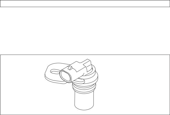
1–5. SPEED SENSORS
There are three speed sensors available for use with 1000 and 2000 Product Families transmissions: the input (engine) speed sensor, the turbine speed sensor, and the output speed sensor (refer to Figure 1–7). The speed sensors provide rpm information to the TCM. The speed ratios between the various sensors allow the TCM to determine the transmission operating range. Speed sensor information is also used to control the timing of clutch apply pressures, resulting in the best possible shift quality.
V04736
Figure 1–7. Typical Speed Sensor
The speed sensors are variable reluctance devices which convert mechanical motion to an AC voltage. Each sensor consists of a wire coil wrapped around a pole piece that is adjacent to a permanent magnet. These elements are contained in a housing which is mounted adjacent to a rotating ferrous member (such as a gear tooth). Two signal wires extend from one end of the housing and an exposed end of the pole piece is at the opposite end of the housing. The permanent magnet produces lines of flux around the pole piece. As a ferrous object (such as a gear tooth) approaches and passes through the gap at the end of the pole piece, an AC voltage pulse is induced in the wire coil. The TCM calculates the frequency of these AC pulses and converts it to a speed value. The AC voltage generated varies from 150mV at low speed to 15V at high speed. The signal wires from the sensor are formed as twisted pairs to cancel magnetically induced fields. The cable is also shielded to protect from voltage-related fields. Noise from other sources is eliminated by using two-wire differential inputs at the TCM.
NOTE: Do not rotate the speed sensor in the retaining bracket. Orientation is fixed, and if changed, may cause improper operation.
A.Input (Engine) Speed Sensor
The input speed sensor is externally mounted in the torque converter housing directed at the ribs protruding from the torque converter. The input speed sensor connector should be positioned at approximately four o’clock, as viewed from the left side of the transmission (refer to Figure 1–8).
B.Turbine Speed Sensor
The turbine speed sensor is externally mounted in the main housing directed at the tone wheel or PTO drive gear attached to the rotating clutch module. The turbine speed sensor connector should be positioned at approximately three o’clock, as viewed from the left side of the transmission (refer to Figure 1–8).
1–6 |
Copyright© 2007 Allison Transmission, Inc. |

1000 AND 2000 PRODUCT FAMILIES TROUBLESHOOTING MANUAL—ALLISON 4th GENERATION CONTROLS
GENERAL DESCRIPTION
C.Output Speed Sensor
The output speed sensor is externally mounted in the rear cover and directed at the teeth of a tone wheel splined to and rotating with the output shaft. The output speed sensor connector should be positioned at approximately five o’clock, as viewed from the left side of the transmission (refer to Figure 1–8).
ENGINE SPEED |
TURBINE SPEED |
SENSOR CONNECTOR |
SENSOR CONNECTOR |
ORIENTATION = 4 o'clock |
ORIENTATION = 3 o'clock |
OUTPUT SPEED
SENSOR CONNECTOR
ORIENTATION = 5 o'clock
V06457.01.00
Figure 1–8. Speed Sensor Connector Orientation
1–6. CONTROL VALVE ASSEMBLY
The hydraulic control valve assembly (Figure 1–9) governs fluid flow to the clutches (including the torque converter clutch). Solenoids, actuated by the TCM, control valve movement.
The control valve assembly consists of two components, the main valve body and the control valve body. The main valve body contains the pressure control valves (PCV), the TCC valve, the exhaust backfill valve, and the control main relief valve. The shift valve body contains the shift valves, the control main pressure valve, and the manual selector valve. The control valve assembly attaches to the bottom of the gearbox module and is enclosed by the oil pan. An internal wiring harness connects the solenoids and Pressure Switch Manifold (PSM) to the main transmission connector and external wiring harness.
Copyright© 2007 Allison Transmission, Inc. |
1–7 |

1000 AND 2000 PRODUCT FAMILIES TROUBLESHOOTING MANUAL—ALLISON 4th GENERATION CONTROLS
GENERAL DESCRIPTION
A.Main Modulation
Main pressure is reduced by utilizing an on/off Main Mod solenoid that is located in the control valve body assembly. The Main Mod solenoid body is bolted to the main valve body. Main pressure will be reduced under various conditions such as low throttle, low torque, low engine speeds, and low output speeds. The primary benefit of modulating main pressure is to increase cooler flow at low engine speeds.


 SS1
SS1
|
|
PCS1 |
|
|
PCS2 |
|
SS2 |
SS3 |
MAIN MOD |
|
|
|
TCC |
V07476.02.01 |
Figure 1–9. Control Valve Assembly
1–7. WIRING HARNESS
A.External Wiring Harness
The external wiring harness (refer to Figure 1–10) requirements are typically met through the use of a single harness with one branch connecting the TCM to the transmission, throttle position sensor, IMS, and speed sensors; another branch connecting the TCM to Allison DOC™ For PC–Service Tool and other vehicle interfaces. All wiring harnesses and mating connectors are OEM-supplied.
NOTE: Repair parts for the external harness and external harness components must be obtained through the vehicle OEM. The OEM is responsible for warranty on these parts.
1–8 |
Copyright© 2007 Allison Transmission, Inc. |

1000 AND 2000 PRODUCT FAMILIES TROUBLESHOOTING MANUAL—ALLISON 4th GENERATION CONTROLS
GENERAL DESCRIPTION
TRANSMISSION
CONTROL
MODULE (TCM)
TRANSMISSION
HARNESS
80-WAY CONNECTOR
J1939
CONNECTOR
OEM SUPPLIED
INTERFACE HARNESS
ENGINE
SPEED SENSOR
CONNECTOR
OUTPUT
SPEED SENSOR
 CONNECTOR
TURBINE
SPEED SENSOR
CONNECTOR
THROTTLE POSITION SENSOR (TPS) CONNECTOR (OPTIONAL)
THROTTLE
POSITION
SENSOR (TPS)
24-WAY MAIN |
20-WAY |
TRANSMISSION |
CONNECTOR |
CONNECTOR |
(OPTIONAL) |
NOTE: Illustration is not to scale. Actual harness configuration may differ from this illustration.
V06475.03.00
Figure 1–10. Typical External Wiring Harnesses
Copyright© 2007 Allison Transmission, Inc. |
1–9 |

1000 AND 2000 PRODUCT FAMILIES TROUBLESHOOTING MANUAL—ALLISON 4th GENERATION CONTROLS
GENERAL DESCRIPTION
B.Internal Wiring Harness
An internal wiring harness (refer to Figure 1–11 and Figure 1–12) connects the shift solenoids (SS1, SS2, SS3), pressure control solenoids (PCS1, PCS2), torque converter clutch solenoid (TCC), internal mode switch (IMS), pressure switch manifold (PSM), and temperature sensor to the external harness leading to the TCM.
SS1 |
MAIN |
A B |
|
|
TRANSMISSION |
GRAY |
CONNECTOR |
|
MAIN
MOD
A B
PSM 
GRAY |
A B C D E F |
LOCKARM
 PCS1
PCS1 

 2
2


 1
1 

IMS |
PCS2 |
LOCKARM |
INTERNAL |
|
|
|
|
|
MODE |
2 |
1 |
SWITCH |
SS3 |
|
A B C D E F |
A B
LOCKARM |
TCC |
SS2 |
GRAY |
|
A B |
||
|
|
2 
 1
1
GRAY
V08975.00.00
Figure 1–11. Typical Internal Wiring Harness (24-Way Connector)
SS1 |
MAIN |
A B |
|
|
TRANSMISSION |
GRAY |
CONNECTOR |
|
MAIN
MOD
A B
PSM 
GRAY |
A B C D E F |
LOCKARM
 PCS1
PCS1 

 2
2


 1
1 

LOCKARM
IMS |
PCS2 |
|
INTERNAL |
2 1 |
|
|
|
|
MODE |
|
|
SWITCH 
 SS3
SS3
A B C D E F |
|
|
|
A B |
LOCKARM |
TCC |
SS2 |
GRAY |
|
A B |
|
|
|
|
|
2 
 1
1
GRAY
V08974.00.00
Figure 1–12. Typical Internal Wiring Harness (20-Way Connector for GM Applications Only)
1–10 |
Copyright© 2007 Allison Transmission, Inc. |

1000 AND 2000 PRODUCT FAMILIES TROUBLESHOOTING MANUAL—ALLISON 4th GENERATION CONTROLS
GENERAL DESCRIPTION
1–8. SPECIAL ELECTRONIC/ELECTRICAL TOOLS
All tools listed are essential for overhaul, maintenance, and/or recalibration of the 1000 and 2000 Product Families electronic and electrical systems. The tools listed below are available for purchase from SPX/Kent-Moore.
Table 1–1. Essential Tools
x
COM |
A |
10 A
J 39700 |
J 42455-A |
J 44950 |
J34520-A Digital
Volt/Ohmmeter
J 39700
Univeral Breakout Box
J 42455-A
Load Box
J 44950
Allison DOC™ For
PC–Service Tool
J 47275
TCM Breakout
Harness Adapter
J 47275
J 47276
“T” Breakout and TCM
Reflashing Harness
J 47276
J 47277
Terminal Probe
NOTE: J 47277 is now included in the J 39197-A Kit.
J 47278
1000 and 2000 Product
Families Breakout Harness
Copyright© 2007 Allison Transmission, Inc. |
1–11 |

1000 AND 2000 PRODUCT FAMILIES TROUBLESHOOTING MANUAL—ALLISON 4th GENERATION CONTROLS
GENERAL DESCRIPTION
Table 1–1. Essential Tools (cont’d)
J 47943
DPA4 USB
J 47949
Translator Device
GMLAN Cable
J 47943 |
J 47949 |
|
J 47944
1000 and 2000 Product
Families Main
Transmission Connector
Removal Tool
J 47944
Table 1–2. Available Tools
J 38125-12A
Terminal Remover (80-way connector) GM P/N: 12094429
J 38125-12A
J 39197-A
Jumper Kit
J 39197-A
J 44722-3 Overlay
J 44722-3 Cable
NOTE: J-44722-3 overlay is for pick-up truck use only.
J 47139
Crimper
J 47139
1–12 |
Copyright© 2007 Allison Transmission, Inc. |
1000 AND 2000 PRODUCT FAMILIES TROUBLESHOOTING MANUAL—ALLISON 4th GENERATION CONTROLS
SECTION 2—DEFINITIONS AND ABBREVIATIONS
2–1. CHECK TRANS LIGHT
The electronic control system is programmed to inform the operator of a problem with the transmission system and automatically take action to protect the operator, vehicle, and transmission. To do this, the TCM turns on the CHECK TRANS light on the instrument panel, which notifies the operator that a Diagnostic Trouble Code (DTC) has been stored.
Each time the engine is started, the TCM will illuminate the CHECK TRANS light, then turn it off after a few seconds. This is a circuit check to verify that the lamp and wiring are in proper working order. Illumination of the CHECK TRANS light at any time after start-up indicates that the TCM has set a DTC. Allison DOC™ For PC– Service Tool is used to verify that the TCM has set a DTC (refer to Section 2–2). While the CHECK TRANS light is on, upshifts and downshifts may be restricted and direction changes (D–R, R–D) may not occur. The torque converter clutch is inhibited when transmission shifting is restricted or during any critical transmission malfunction.
The 1000 and 2000 Product Families transmissions DTCs are latching DTCs. When a failure condition is detected, the DTC set by the TCM remains active for the entire time the ignition is on. When the ignition is turned off and then on again, the transmission DTCs will reset and the TCM will recheck for the failure condition. If the failure condition is not present, the previously set DTC will remain in history; the CHECK TRANS light will turn off after the circuit check, and the transmission will function normally unless another failure occurs. This feature allows the vehicle to be driven to a service outlet.
2–2. RANGE INHIBIT RESPONSES
The range inhibit feature is a function of the TCM logic. The TCM senses when certain input variables are exceeded and takes action to prevent transmission damage. The TCM inhibits neutral-to-range shifts and illuminates a light on the dash when the inhibit is active.
Listed below are three variables that, when exceeded, cause inhibited shifts (with thresholds listed).
•Engine speed above 1000 rpm
•Throttle setting above 40 percent
•Output speed above 225 rpm
There are two levels of the special logic inhibits.
•Self-clearing inhibit—This inhibit clears itself if one of the above conditions is not present after a calibrated time. This is three seconds in the case of medium-duty vehicles. If the shift inhibit is active, but not latched, the bulb will stay lit until self-cleared.
•Latching inhibit — This inhibit latches when one of the conditions listed above is still present after a calibrated time. This is above three seconds for medium duty vehicles. To clear a latching inhibit, move the selector into any other position than the one originally selected.
2–3. ALLISON DOC™ FOR PC–SERVICE TOOL INHIBITS
If an inhibit has occurred since the last DTC was cleared, the inhibit state will indicate ON and will stay ON until the next manual DTC clear with Allison DOC™ For PC–Service Tool. These latched inhibits do not turn OFF after a specified number ignition cycles.
Copyright© 2007 Allison Transmission, Inc. |
2–1 |

1000 AND 2000 PRODUCT FAMILIES TROUBLESHOOTING MANUAL—ALLISON 4th GENERATION CONTROLS
DEFINITIONS AND ABBREVIATIONS
The range inhibit light will illuminate and/or an inhibited state will be shown on Allison DOC™ For PC–Service Tool when the transmission is inhibited to Neutral for the following reasons:
•Low Main Pressure
If the transmission pressure switches do not indicate transmission pressurized at start-up, shifts-to-range may be inhibited and the range inhibit light will illuminate. Allison DOC™ For PC–Service Tool will indicate an active inhibit.
Common causes are transmission low on fluid, transmission filter has just been changed, or pan has been removed and fluid recently drained.
May produce DTC P0701.
•Transfer Case Neutral
If the transfer case is shifted into neutral while the transmission is in drive or reverse at a speed above idle, the transmission will continue to command range until the output speed is reduced to a point where neutral range is commanded. The range inhibit light will illuminate and Allison DOC™ For PC–Service Tool will indicate an active inhibit.
•Diagnostic Active
This indicates that an active diagnostic code was set and the driver attempted a range selection that was inhibited. In some failure modes, reverse cannot and will not be commanded. If reverse is selected during these failure modes a range inhibit light will illuminate in reverse.
During diagnostic responses, Neutral-to-Range Inhibits and Direction Change Inhibits continue to operate, but they may latch under certain conditions. In these cases, shutting down ignition and waiting for at least 5 seconds before restarting will clear the inhibit condition. Allison DOC™ For PC–Service Tool will indicate an active inhibit.
•Auto Neutral for PTO
Neutral-to-Drive and Neutral-to-Reverse shifts will be inhibited to neutral and Allison DOC™ For PC–Service Tool will show an inhibited state when TCM detects that auto neutral function input is active.
•Reverse Enable
Neutral-to-Reverse shifts will be inhibited to neutral and Allison DOC™ For PC–Service Tool will show an inhibited state when no input is detected from dash or floor mounted reverse enable switch when selecting reverse range. Allison DOC™ For PC–Service Tool will indicate an active inhibit.
This function is only used in European transit and tour buses applications.
•Refuse Packer Step Switch
Transmission operation is limited to only 1st range. Neutral-to-reverse shifts will be inhibited to neutral and Allison DOC™ For PC–Service Tool will show an inhibited state when input is detected from a step switch indicating that personnel is present on rear step platform.
•Auxiliary Function Range Inhibit
Neutral-to-Drive and Neutral-to-Reverse shifts will be inhibited to neutral and Allison DOC™ For PC–Service Tool will show an inhibited state when input is detected from an auxiliary switch or device. This inhibit will remain active until the auxiliary switch input is shut off and range is reselected.
2–2 |
Copyright© 2007 Allison Transmission, Inc. |

1000 AND 2000 PRODUCT FAMILIES TROUBLESHOOTING MANUAL—ALLISON 4th GENERATION CONTROLS
DEFINITIONS AND ABBREVIATIONS
•PTO Neutral Lockup
Allison DOC™ For PC–Service Tool will show an inhibited state when Neutral Lockup is active and range shifts are being inhibited to neutral. When the selector is moved, lockup is released and the inhibit clears.
•Engine Speed
Neutral-to-Drive and Neutral-to-Reverse shifts will be inhibited to neutral and the range inhibit light will illuminate if the Engine Speed is greater than a calibrated value (1400 rpm for medium duty non-emergency vehicles). Allison DOC™ For PC–Service Tool will indicate an active inhibit.
•Output Speed
Reverse-to-Drive, Drive-to-Reverse, and Neutral-to-Reverse shifts initiated above 300 rpm of output speed will be inhibited to neutral and the range inhibit light will illuminate. Allison DOC™ For PC– Service Tool will indicate an active inhibit.
•Throttle
Reverse-to-Drive, Drive-to-Reverse, Neutral-to-Drive, and Neutral-to-Reverse shifts where throttle position is greater then 25 percent will be inhibited to neutral and the range inhibit light will illuminate. Allison DOC™ For PC–Service Tool will indicate an active inhibit.
•IMS Function or Alignment
Reverse-to-Drive, Drive-to-Reverse, Neutral-to-Drive, and Neutral-to-Reverse shifts will be inhibited to neutral and the range inhibit light will illuminate when an IMS failure or misalignment is detected. A common cause would be an error in the four-bit IMS input signal that is sent to the TCM.
Allison DOC™ For PC–Service Tool will indicate an active inhibit.
•IMS PS4 Disagree
Reverse-to-Drive, Drive-to-Reverse, Neutral-to-Drive, and Neutral-to-Reverse shifts will be inhibited to neutral and the range inhibit light will illuminate when the Pressure Switch 4 (PS4) status is in the incorrect state when compared to the IMS state. Allison DOC™ For PC–Service Tool will indicate an active inhibit. This inhibit may be caused by a defective IMS, PSM, or valve body concerns.
•MSV Mis-Alignment/Unable to detect ratio after shift to range
If the range verification test fails to detect turbine speed pull-down or valid gear ratio when the Manual Selector Valve (MSV) shifts to either forward or reverse range from neutral, the transmission will shift back to a neutral condition and the range inhibit light will illuminate.
Conditions that may cause this include: Attempts to shift the transmission from Neutral-to-Drive or Neutral-to-Reverse with the transfer case in neutral; transmission low on fluid; misadjustment in the IMS or Selector Linkage; turbine or output speed sensor failure that may prevent the pull down test/ratio test from passing; solenoid A or B hydraulically failures; and possibly failed range clutch (C1 or C5 for 1st, C3 or C5 for Reverse).
Allison DOC™ For PC–Service Tool will indicate an active inhibit response.
•Wheel Spin or Lock
When the TCM detects that wheel lock or spin is occurring, the TCC is disengaged and a lock-to-range response is commanded for 6 seconds. Allison DOC™ For PC–Service Tool will indicate an active inhibit response.
Copyright© 2007 Allison Transmission, Inc. |
2–3 |

1000 AND 2000 PRODUCT FAMILIES TROUBLESHOOTING MANUAL—ALLISON 4th GENERATION CONTROLS
DEFINITIONS AND ABBREVIATIONS
2–4. ALLISON DOC™ FOR PC–SERVICE TOOL
Allison DOC™ For PC–Service Tool v5.0.0 (or later) is available through Kent-Moore Heavy-Duty Division. When installed on a Windows® PC, the Allison DOC™ For PC–Service Tool (refer to Figure 2–1) transmits and receives data to and from the TCM via the vehicle data communications link, processes the data, and displays appropriate information. Use Allison DOC™ For PC–Service Tool during installation checkout and troubleshooting.
For more details on Allison DOC™ For PC–Service Tool features, refer to the User Guide for Allison DOC™ For PC–Service Tool Version 5.0.0, GN3433EN.
V05490
Figure 2–1. Allison DOC™ For PC–Service Tool
2–4 |
Copyright© 2007 Allison Transmission, Inc. |

1000 AND 2000 PRODUCT FAMILIES TROUBLESHOOTING MANUAL—ALLISON 4th GENERATION CONTROLS
DEFINITIONS AND ABBREVIATIONS
2–5. ABBREVIATIONS
A/N |
Assembly Number |
ABS |
Anti-lock Brake System—OEM-provided means to detect and prevent wheel stoppage to |
|
enhance vehicle handling. Retarder and engine brakes will not apply when ABS is active. |
Amp |
Ampere—Unit of electrical current |
CAN |
Controller Area Network—A network for all SAE J1939 communications in a vehicle |
|
(engine, transmission, diagnostics, ABS, etc.) |
CC |
Calibration Compatibility—First two digits of the CIN |
CIN |
Calibration Identification Number—Used to identify transmission controls software level |
CMC |
Customer Modifiable Constants |
CT |
Closed Throttle |
DNA |
Does Not Adapt—Adaptive shift control is disabled. |
DNS |
DO NOT SHIFT—Refers to the DO NOT SHIFT diagnostic response during which the |
|
CHECK TRANS light is illuminated and the transmission will not shift and will not |
|
respond to the Shift Selector. |
DTC |
Diagnostic Trouble Code |
DVOM |
Digital volt/ohmmeter |
ECM |
Engine Controller Module—Available on electronically-controlled engines—provides |
|
some relevant data to TCM. |
EMI |
ElectroMagnetic Interference |
GPI |
General Purpose Input—Input signal to the TCM to request a special operating mode or |
|
condition. |
GPO |
General Purpose Output—Output signal from the TCM to control vehicle components |
|
(such as PTOs, backup lights, etc.) or allow a special operating mode or condition. |
IMS |
Internal Mode Switch |
IPC |
Instrument Panel Controller |
J 1939 |
High-speed vehicle serial data communications standard. |
LED |
Light-Emitting Diode—Electronic device used for illumination. |
LRTP |
Low-Range Torque Protection—A feature limiting engine torque in lower ranges and |
|
reverse to protect the transmission from damage. |
NVL |
Neutral Very Low—The TCM has sensed turbine speed below 150 rpm. This is usually |
|
caused by a dragging C1 or C3 clutch or a failed turbine speed sensor. When attained, the |
|
C4 and C5 clutches are applied to lock the transmission output. |
OBD II |
On Board Diagnostics Second generation. EPA mandated specification for vehicle |
|
diagnostics. |
OEM |
Original Equipment Manufacturer—Maker of vehicle or equipment. |
Ohm |
Unit of electrical resistance. |
PC |
Personal Computer |
PCCS |
Production Calibration Configuration System |
Copyright© 2007 Allison Transmission, Inc. |
2–5 |

1000 AND 2000 PRODUCT FAMILIES TROUBLESHOOTING MANUAL—ALLISON 4th GENERATION CONTROLS
DEFINITIONS AND ABBREVIATIONS
2–5. ABBREVIATIONS (cont’d)
PCM |
Powertrain Controller Module—Electronic device used on some vehicles. |
PCS |
Pressure Control Solenoid |
PCV |
Pressure Control Valve |
PDM |
Parallel Data Module |
PPC |
Pressure Proportional to Current solenoid. Solenoid control of clutch pressure is |
|
proportional to the current being supplied to the solenoid. |
PROM |
Programmable Read Only Memory |
PS |
Pressure Switch |
PSM |
Pressure Switch Manifold—Part of transmission control system located inside the oil pan. |
PTO |
Power Takeoff |
PWM |
Pulse Width Modulation |
RFI |
Radio Frequency Interference |
RPR |
Return to Previous Range—Diagnostic response in which the transmission is commanded |
|
to return to previously commanded range. |
SEM |
Shift Energy Management—Allows the TCM to request torque reduction from the ECM |
|
during upshifts for increased clutch life. |
SOL OFF |
All SOLenoids OFF |
SS |
Shift Solenoid |
SV |
Shift Valve |
TBC |
Truck Body Controller |
TCC |
Torque Converter Clutch |
TCM |
Transmission Control Module (also commonly referred to as the “computer”) |
TFT |
Transmission Fluid Temperature—Data provided by thermistor that is part of the PSM. |
TPS |
Throttle Position Sensor—Potentiometer for signaling the position of the engine fuel |
|
control lever. |
V |
Version—Abbreviation used in describing TCM software levels. |
VBS |
Variable Bleed Solenoid—Another name for Pressure Proportional to Current (PPC) |
|
solenoid. Solenoid control of clutch pressure is proportional to the current being supplied |
|
to the solenoid. |
VDC |
Volts Direct Current (DC) |
VIW |
Vehicle Interface Wiring—Interfaces TCM programmed input and output functions with |
|
the vehicle wiring. |
Volt |
Unit of electrical force |
VOM |
Volt/ohmmeter |
WOT |
Wide Open Throttle |
∞ |
Infinity—Condition of a circuit with higher resistance than can be measured; effectively an |
|
open circuit. |
2–6 |
Copyright© 2007 Allison Transmission, Inc. |

1000 AND 2000 PRODUCT FAMILIES TROUBLESHOOTING MANUAL—ALLISON 4th GENERATION CONTROLS
SECTION 3—BASIC KNOWLEDGE
3–1. BASIC KNOWLEDGE REQUIRED
To service 1000 and 2000 Product Families Allison 4th Generation Controls, the technician must understand basic electrical concepts. Technicians need to know how to use a digital volt/ohmmeter (DVOM) to make resistance and continuity checks. Most troubleshooting checks consist of checking resistance and continuity, and checking for shorts between wires and to ground. The technician should be able to use jumper wires and breakout harnesses and connectors. Technicians unsure of making the required checks should ask questions of experienced personnel or find instruction.
The technician should also have the mechanical aptitude required to connect pressure gauges or transducers to identified pressure ports used in the troubleshooting process. Pressure tap locations and pressure values are shown in Appendix B—Main Pressure Check Procedure.
Input power, ground, neutral start circuitry, etc., can cause problems with electronic controls or vehicle functioning and may not generate a DTC. A working knowledge of 1000 and 2000 Product Families Allison 4th Generation Controls vehicle installation is necessary in troubleshooting installation-related problems.
Refer to Section 7 for information concerning performance complaints (non-DTC) troubleshooting. A complete wiring schematic is shown in Appendix J. Refer to the 1000 and 2000 Product Family Tech Data for information concerning electronic controls installation and the Installation Checklist. Reliable transmission operation and performance depend upon a correctly installed transmission. For proper installation, review the Installation Checklist in the 1000 and 2000 Product Family Tech Data, available on the extranet under Engineering at www.allisontransmission.com.
3–2. USING THE TROUBLESHOOTING MANUAL
Use this manual as an aid to troubleshooting the 1000 and 2000 Product Families Allison 4th Generation Controls. Every possible problem and its solution cannot be encompassed by any manual. However, this manual does provide a starting point from which most problems can be resolved.
Once a problem solution is discovered in the manual do not look further for other solutions. It is necessary to determine why a problem occurred. The root cause of a problem as well as the symptom must be corrected to ensure trouble free operation. For example, taping a wire that has been rubbing on a frame rail will not correct the problem unless the rubbing contact is eliminated.
3–3. SYSTEM OVERVIEW
1000 and 2000 Product Families Allison 4th Generation Control functions are controlled by the TCM. The TCM reads shift selector range selection, output speed, and throttle position to determine when to command a shift. When a shift occurs, the TCM monitors turbine speed, output speed, and throttle position to control the oncoming and off-going clutches during the shift.
When the TCM detects an electrical fault, it logs a DTC indicating the faulty circuit and may alter the transmission operation to prevent or reduce damage.
When the TCM detects a non-electrical problem while trying to make a shift, the TCM may try that shift a second or third time before setting a DTC. Once that shift has been retried, and a fault is still detected, the TCM sets a DTC and holds the transmission in a fail-to-range mode of operation.
Copyright© 2007 Allison Transmission, Inc. |
3–1 |

1000 AND 2000 PRODUCT FAMILIES TROUBLESHOOTING MANUAL—ALLISON 4th GENERATION CONTROLS
BASIC KNOWLEDGE
The 1000 and 2000 Product Families transmission utilizes “clutch to clutch” shift control to achieve range changes. In every case (except shifts to or from neutral), one clutch is exhausted and another applied to make a range shift. The “handoff” between exhausting and applying clutches is very precisely controlled by use of two Variable-Bleed Solenoids (VBS), commonly known as Pressure Proportional to Current (PPC) solenoids. These solenoids are labelled PCS1 and PCS2 in the transmission, and are referred to as “pressure control” solenoids. For example, to make a 1–2 shift, PCS1 is used to trim pressure off C5 clutch, and PCS2 is used to trim pressure on C4 clutch.
The TCM (transmission control module) modulates the current to both PCS1 and PCS2, which translates to a proportional level of pressure to the clutch. In order to make a shift, the TCM uses software and calibration settings of several program parameters to determine the level of current sent to the respective pressure control solenoids. These parameters are referred to as “adaptive values.” With a new transmission and TCM calibration, the adaptive values are set to “base calibration” level. The transmission uses the base calibration to perform the first of each type of shift. However, once it has performed a shift, the TCM evaluates the actual shift and compares it to an “ideal” shift in the TCM’s memory. Based on that comparison, the TCM changes the settings of the adaptive values to a level that it believes will result in a shift closer to the “ideal” shift the next time it makes that type of shift. This is referred to as “adaptive shifting.”
When the transmission/TCM calibration is new, the TCM is in “fast adaptive” mode. In other words, the TCM is allowed to make relatively large changes in the adaptive values after each shift. Once the TCM determines that a given shift is close to its ideal level it switches to “slow adaptive” mode. In slow adaptive the TCM still is evaluating shifts and changing adaptive values, but is only allowed to do so in smaller increments.
The TCM is programmed to try to switch from fast to slow adaptive mode within approximately five shifts. It is important to understand that there are many different distinct shifts recognized by the TCM, and each of these shifts has its own adaptive values. For example, there are upshift and downshifts to and from each range, as well as unique adaptive values for several different throttle regions for each upshift and downshift. The point is, it may take a significant amount of time before most of the shifts converge from fast to slow adaptive, and thus it is not unusual to experience somewhat harsh or unpleasant shift quality until these shifts are adapted.
TCC engagement is accomplished by a separate PPC (pressure proportional to current) TCC solenoid. There are adaptive values for this as well, and thus it will also require some driving for TCC engagement to adapt.
3–4. IMPORTANT INFORMATION IN THE TROUBLESHOOTING PROCESS
Before beginning the troubleshooting process, read and understand the following:
•Allison recommended wire numbers (i.e. 112) are a combination of the first digit indicating the TCM 80-way connector number and the last two digits indicating the pin-out information (i.e. 12).
•Shut off the engine and ignition before any harness connectors are disconnected or connected.
•Remember to do the following when checking for shorts and opens:
—Minimize movement of wiring harnesses when looking for shorts. Shorts involve wire-to-wire or wire-to- ground contacts and moving the harnesses may eliminate the problem.
—Wiggle connectors, harnesses, and splices when looking for opens. This simulates vehicle movements which occur during actual operation.
•When disconnecting a harness connector, be sure that pulling force is applied to the connector itself and not the wires extending from the connector.
•Resistance checks involving the wiring between the TCM connectors and other components adds about one Ohm of resistance to the component resistance shown.
3–2 |
Copyright© 2007 Allison Transmission, Inc. |

1000 AND 2000 PRODUCT FAMILIES TROUBLESHOOTING MANUAL—ALLISON 4th GENERATION CONTROLS
BASIC KNOWLEDGE
•Inspect all connector terminals for damage. Terminals may have bent or lost the necessary tension to maintain firm contact.
•Clean dirty terminals or connectors with isopropyl alcohol and a cotton swab, or a good quality, non-residue, non-lubricating, cleaning solvent such as LPS Electro Contact Cleaner® or LPS NoFlash Electro Contact Cleaner®.
|
The cleaning solvent must not be chlorine based, contain petroleum distillates, or |
|
|
conduct electricity. The cleaning solvent should evaporate quickly to prevent the |
|
CAUTION: |
possibility of condensation within the connectors. Always blow or shake any excess |
|
cleaner from the connector before assembling it to its mating connector or hardware. |
||
|
||
|
Cleaner trapped in the connector can affect the connector seal. (Refer to |
|
|
SIL 17-TR-94 for detailed information on the recommended cleaners.) |
|
|
|
CAUTION: |
Care should be taken when welding on a vehicle equipped with electronic controls. |
|
Refer to Appendix G. |
||
|
•DTCs displayed after system power is turned on while a harness connector is disconnected can be ignored and cleared from memory. Refer to Section 5, DTCs, for the DTC clearing procedure.
3–5. BASIC TROUBLESHOOTING INFORMATION
1.Begin troubleshooting by checking the transmission fluid level and ignition voltage. Remember that some problems may be temperature related. Do troubleshooting, including the fluid level and ignition voltage checks, at the temperature level where the problem occurs.
NOTE: Fluid level and igniton voltage MUST be checked before any troubleshooting is performed.
NOTE: If you are experiencing harsh shifts, it is important to use Allison DOC™ For PC–Service Tool to verify whether that particular shift is adapted. If it is not, the TCM is still “learning” how to adapt that shift and simply needs to be driven further while performing more of that particular type of shift.
If a particular shift is in slow adapt but still objectionable, it’s good troubleshooting practice to reset the adaptive values for that shift back to “base cal” level. This will automatically reset the TCM to fast adaptive mode. The vehicle should then be driven to allow the TCM to “re-learn” the shift. Many times this will correct the problem. It is possible to reset individual shifts without affecting the other shifts.
Whenever a transmission is overhauled, exchanged, or has undergone repairs, the Transmission Control Module (TCM) must be “RESET TO UNADAPTED
CAUTION: SHIFTS.” This will cause the TCM to erase previous adaptive information and begin to adapt in Fast Adaptive Mode from the base calibration. Failure to follow this
procedure may cause premature failure of the overhauled, repaired, or replaced transmission.
Copyright© 2007 Allison Transmission, Inc. |
3–3 |

1000 AND 2000 PRODUCT FAMILIES TROUBLESHOOTING MANUAL—ALLISON 4th GENERATION CONTROLS
BASIC KNOWLEDGE
2.If a transmission has been overhauled, exchanged, or repaired, use Allison DOC™ For PC–Service Tool to “RESET ADAPTIVE SHIFT PARAMETERS.”
To reset Adaptive Shift Parameters:
•Select the Action Request drop-down menu.
•Click on the Reset Adaptive Shift Parameters menu item—the Reset Adaptive Parameters window displays.
•The Reset Adaptive Shift Parameters window contains 10 tabs; one for each upshift and downshift region, garage shifts and a reset tab for All regions.
—To reset all adaptive shift parameters, select the ALL tab.
—The adaptive shift parameters are reset when you click on the RESET ADAPTIVE SHIFT PARAMETERS button—the Reset Adaptive Shift Parameters Successful window displays. Click the OK button.
3.For proper operation of Allison DOC™ For PC–Service Tool v5.0.0 or later, check the following:
•The desktop or laptop computer must meet the minimum system requirements (see Allison DOC™ For PC–Service Tool Version 5.0.0 User Guide, GN3433EN):
—Microsoft Windows® 2000 Professional (SP4 or later) or Windows® XP Professional
—600 MB free hard drive space
—20 GB hard drive (40 GB preferred)
—128 MB of RAM (256 MB preferred)
—Intel® Pentium® III or IV processor
—Available USB 1.1 or 2.0 port
—1024 x 768 screen resolution
—256-color palette
—Small fonts
—Internet connection (Internet Explorer 5.0 or greater)
—A media player program (Windows Media Player® is provided on the Allison DOC™ For PC–Service Tool For PC CD)
—Adobe® Acrobat® Reader® (provided on the Allison DOC™ For PC–Service Tool CD)
—CD-ROM 16x minimum (48x preferred)
NOTE: Refer to the CD Readme.txt file for more information.
•The proper driver (electronic file) is installed for the Computer Interface Module.
•Power at the Deutsch 9-pin diagnostic connector (pin A is negative, pin B is positive).
•The proper connections exist for communicating with Allison DOC™ For PC–Service Tool (Figure 3–1 and Figure 3–2).
Presently there are two communication standards for Allison DOC™ For PC–Service Tool diagnostic software: J1939 and GMLAN J2284. Both standards are supported by Allison DOC™ For PC– Service Tool (versions 5.0).
3–4 |
Copyright© 2007 Allison Transmission, Inc. |
 Loading...