


Dear Client,
Thank you for choosing Alfa Romeo.
Your Alfa GT has been designed to guarantee the safety, comfort and driving pleasure typical of Alfa Romeo.
This booklet will help you to get to know the characteristics and operation of your car.
The following pages contain all the indications necessary for you to be able to maintain the high standards of performance, quality, safety and respect for the environment which characterise this Alfa GT.
The enclosed Warranty Booklet also contains the regulations, the warranty certificate and a guide to the services offered by Alfa Romeo.
Services which are essential and precious because, when you purchase an Alfa Romeo, you are not only acquiring a car, but the tranquillity that comes from knowing that an efficient, willing and widespread organisation is at your service for any assistance problems you may have.
Nature benefits in two ways: there’s no pollution from waste disposal and the demand for raw materials is reduced.
Enjoy the reading. And have a good trip.
This booklet describes all the versions of the Alfa GT, so you should only consider the information concerning the trim level, engine and version purchased by you.
1

VERY IMPORTANT!
FUEL CAPACITY
K |
Petrol engines: only use unleaded petrol with no less than 95 R.O.N. |
Diesel engines: only refuel with diesel fuel conforming to the European specification EN590. The use of other products or |
|
mixtures may irreparably damage the engine with invalidation of the warranty due to the damage caused. |
STARTING THE ENGINE
Petrol engines with mechanical transmission: make sure that the handbrake is engaged; set the gearshift lever to neutral, fully depress the clutch without pressing the accelerator, then turn the ignition key to AVV and release it as soon as the engine has started.
Petrol engine with Selespeed transmission: keep the brake pedal fully depressed, turn the ignition key to AVV and release it as soon as the engine has started; the transmission sets to neutral automatically (the display shows position N).
JTD engines: turn the ignition key to MAR and wait for the Y and m warning lights to go off; turn the ignition key to AVV and release it as soon as the engine has started.
PARKING ON FLAMMABLE MATERIAL
While working, the catalyst develops a very high temperature. Do not park the car over grass, dry leaves, pine needles or
any other inflammable materials: risk of fire.
2

RESPECTING THE ENVIRONMENT
The car is fitted with a system that allows continuous diagnosis of the components correlated with emissions to ensure bet-
Uter respect for the environment.
ACCESSORY ELECTRICAL DEVICES
the battery), contact Alfa Romeo Authorised Services who will assess the overall electrical absorption and check whether the car system is able to withstand the load required.If after purchasing the car you wish to install accessories that need an electrical supply (with the risk of gradually draining
CODE CARD (for versions/markets where applicable)
Keep it in a safe place, not in the car. IT is advisable to always keep the electronic code on the CODE card with you in case emergency starting is necessary.
SCHEDULED SERVICING
Correct maintenance makes it possible to preserve car performance levels and safety, respect for the environment and low running costs unaltered over the course of time.
THE OWNER HANDBOOK…
…you will find important information, advice and warnings for correct use, driving safety and car maintenance over time. Pay particular attention to the symbols " (personal safety) # (protecting the environment) â (car safety).
3

Any queries concerning servicing should be forwarded to the showroom from which the car was purchased, the subsidiary company or to our branch offices or any point of the Alfa Romeo Network.
Warranty Booklet
The Warranty Booklet is delivered together with every new car and contains the regulations tied to the services given by Alfa Romeo Services and to the warranty conditions.
Correctly carrying out the scheduled services specified by the manufacturer is the best way to maintain the performance, safety characteristics and low running costs of your car. It is also necessary to maintain warranty cover.
“Service” guide
This contains Alfa Romeo Authorised Services. The Services can be recognised by the presence of the Alfa Romeo badge and logo.
The Alfa Romeo organisation in Italy can be found in the telephone directory under the letter “A” Alfa Romeo.
Not all of the models described in this booklet are available in all countries. Only some of the fittings described in this booklet are fitted as standard to the car. The list of available accessories should be requested from the Alfa Romeo Dealers.
4
THE SYMBOLS USED IN THIS BOOKLET
The symbols illustrated in these pages show the subjects which should, in particular, be closely studied.
PERSONAL
SAFETY
Warning. Partially or fully ignoring these rules may lead to
serious injury.
PROTECTING THE
ENVIRONMENT
This indicates the correct procedures to be followed to prevent the car from damaging the environment.
 CAR SAFETY
Warning. Partially or fully ignoring these rules may lead to serious damage being caused to the car which, in some circumstances, may cause forfeiture of the warranty cover.
The texts, illustrations and specifications given in this booklet refer to the car at the time of going to press.
As part of our ongoing striving to improve our products, Alfa Romeo may introduce technical changes during production, therefore the specifications and fittings may be altered without prior notice.
For details on this subject, please apply to the manufacturer’s sales network.
5
CAR |
GETTING TO KNOW YOUR CAR |
|||
YOUR |
SYMBOLS |
THE ALFA ROMEO |
KEYS |
|
|
||||
KNOW |
|
CODE SYSTEM |
The car is delivered with a key with met- |
|
On some of the components making up |
|
al insert (upon request for models/markets |
||
|
where required) and a key with remote con- |
|||
your Alfa GT, or near to them, special |
To increase protection against attempted |
|||
trol. For models/markets where required |
||||
coloured labels have been attached. These |
||||
TO |
theft, the car is fitted with an electronic en- |
two keys with remote control can be pro- |
||
labels bear symbols that remind you of the |
||||
gine lock system (Alfa Romeo CODE) which |
||||
GETTING |
precautions to be taken as regards that par- |
vided. |
||
which modulates the radio frequency signal |
CONTROL (for versions/ |
|||
bonnet. |
||||
|
ticular component. A summary list of the |
is activated automatically when the key is |
|
|
|
symbols (fig.1) is to be found under the |
removed from the ignition. In fact the grip |
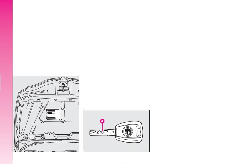
KEY WITHOUT REMOTE |
|
|
of each key contains an electronic device |
|||
|
|
|
||
|
A0A00621b |
transmitted when the engine is started by a |
markets where applicable) |
|
|
|
special aerial incorporated in the ignition |
The fixed metallic insert A-fig. 2 oper- |
|
|
|
switch. This modulated signal is the “pass- |
||
|
|
ates: |
||
|
|
word” by which the control unit recognises |
||
|
|
– the ignition switch; |
||
|
|
the key and only in this condition can the |
||
|
|
engine be started. |
– the driver’s door lock; |
|
|
|
|
||
|
|
|
– the passenger’s Air bag deactivation (up- |
|
|
|
A0A1118b |
on request for versions/markets where ap- |
|
|
|
plicable); |
||
|
|
|
||
|
|
|
– the fuel filler cap lock. |
|
6 |
fig. 1 |
fig. 2 |
|
|
IMPORTANT To guarantee the perfect efficiency of the electronic devices contained in keys, avoid letting them directly exposed to sunrays.
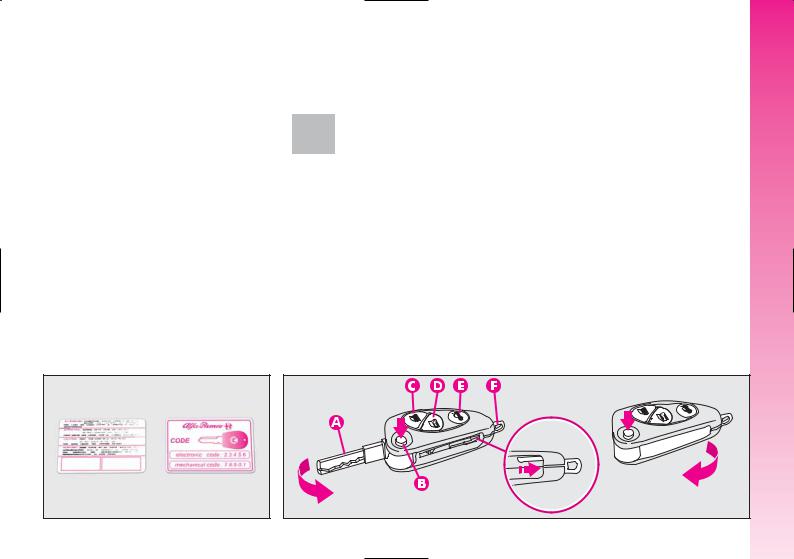
Together with the keys the CODE card is provided (for versions/ markets where applicable) (fig. 3), bearing in print the key codes (both mechanical and electronic for emergency start up).
The code numbers on the CODE card must be kept in a safe place , not in the car.
The driver should always keep the electronic CODE card with him/her in the event of having to carry out emergency starting.
If the car changes owner, the new owner must be given all the keys and the
CODE card.
KEY WITH REMOTE CONTROL
The key with remote control (fig. 4) is fitted with:
–a metal insert (A) that can be enclosed in the key grip
–a button (B) for power-assisted opening of the metal insert
–a button (C) for remote door unlocking and at the same time switching off the electronic alarm
–a button (D) for remote door locking and at the same time switching on the electronic alarm
–a button (E) for remote boot unlocking
–removable hook ring (F).
GETTING TO KNOW YOUR CAR
A0A0003b |
A0A0600b |
fig. 3 |
fig. 4 |
7 |

GETTING TO KNOW YOUR CAR
The metal insert (A) of the key operates:
–the ignition switch
–driver’s door lock and, upon request for versions/markets where applicable, the passenger’s door lock
–the passenger’s side Air bag deactivation switch
To bring the metal insert out of the key grip, press the button (B).
To pull out the hook ring (F) use a finely pointed object (e.g. pen) and work in the direction of the arrow.
The button B should only be pressed when the key is away from the body, in
particular from the eyes, and from objects that can be spoilt (clothes for instance). Make sure the key can never be touched by others, especially children, who may inadvertently press the button.
To insert the metal insert in the key grip:
–keep the button (B) pressed
–move the metal insert (A)
–release the button (B) and turn the metal insert (A) until hearing the click as it locks into place.
To unlock the doors by remote control press button (C), the doors unlock and the direction indicators flash twice. To lock the doors by remote control, press button (D), the doors lock and the direction indicators flash once. Pressing button (C) the doors are released, if within the next 60 seconds a door or the tailgate are not opened, the system automatically locks everything again.
On cars fitted with electronic alarm system, pressing button (C) turns it off, pressing button (D) turns it on.
OPENING THE TAILGATE
The tailgate can be opened from outside by remote control pressing button (E), even if the electronic alarm is on. Opening of the tailgate is accompanied by the direction indicators flashing twice; closing is accompanied by a single flash.
If the electronic alarm is fitted, when the tailgate is opened the alarm system switches off volumetric protection and the tailgate control sensor, the system (with the exception of versions for certain markets) “beeps” twice.
Closing the tailgate again, the control functions are restored, the system “beeps” twice (with the exception of certain markets).
8

OPERATION
Each time the ignition key is turned to the STOP position the Alfa Romeo CODE system deactivates the functions of the engine electronic control unit.
Each time the car is started turning the ignition key to MAR, the Alfa Romeo CODE control unit sends a recognition code to the engine control unit to deactivate the inhibitor. The code is crypted and variable between over four billion possible combinations, and it is sent only if the system control unit has recognised the code transmitted from the key which contains an electronic transmitter, through an aerial wound around the ignition switch.
If the code has not been recognised correctly, the Alfa Romeo CODE warning light (Y) on the cluster turns on.
In this case, the key should be moved to the STOP position and then back to MAR; if the lock continues, possibly try again with the other key provided with the car. If it is still not possible to start the car, follow the instructions given in the “In an emergency” chapter and then contact Alfa Romeo Authorised Services.
IMPORTANT Every key has its own code, which must be memorised by the system control unit. To memorise new keys, up to a maximum of eight, apply solely to Alfa Romeo Authorised Services taking with you all the keys in your possession, the CODE card, a personal identity document and the car’s ownership documents.
The codes of any keys not presented during the memorising procedure are erased. The reason for this is to ensure that any lost or stolen keys cannot be used to start the engine.
IMPORTANT Turning on of the Alfa Romeo CODE warning light (Y) when travelling with the ignition key at MAR:
1)If the warning light turns on, this means that the system is running a self-test (for example for a voltage drop). At the first stop, it will be possible to test the system: switch off the engine turning the ignition key to STOP; then turn the ignition key to MAR: the warning light turns on and should go off in about one second. If the warning light stays on, repeat the procedure described previously leaving the key at STOP for over 30 seconds. Should the inconvenience persists, contact Alfa Romeo Authorised Services.
2)For versions without the reconfigurable multifunction display, the flashing of the warning light means that the car is not protected by the engine inhibitor device. This condition for cars with reconfigurable multifunction display is shown by the turning on of the warning light together with the display of the message: “CODE SYSTEM NOT PRO- GRAMMED”. Contact Alfa Romeo Authorised
Services immediately to have all the keys memorised.
GETTING TO KNOW YOUR CAR
9
GETTING TO KNOW YOUR CAR
If after about 2 seconds with the ignition key at MAR, for versions without
reconfigurable multifunction display, the Alfa Romeo CODE warning light (Y) turns on again flashing, or for versions with reconfigurable multifunction display, the warning light turns on again together with the message “CODE
SYSTEM NOT PROGRAMMED”, this
means that the code of the keys has not been stored, therefore the car is not protected by the Alfa Romeo CODE system against attempted theft. In this case contact Alfa Romeo Authorised Services to have the key codes stored.
KEY BATTERY
REPLACEMENT
If when pressing button (B or C-fig. 6) on the remote control, nothing happens, the battery should be replaced by a new one of the same type to be found c/o normal retailers.
Used batteries are harmful to the environment. They should be disposed of
as specified by law in the special containers provided. Avoid exposure to naked flames and high temperatures. Keep out of reach of children.
Battery replacement:
–press button (A-fig. 5) and move the metal insert (B) to the open position;
–using a finely-tipped screwdriver, turn the opening device (C) and pull out the battery holder (D);
–replace the battery (E) making sure that the bias is correct;
–re-insert the battery holder in the key and lock it, turning the device (C).
A0A0603b
10 |
fig. 5 |
ELECTRONIC ALARM
DESCRIPTION
The system comprises: a transmitter, receiver, control unit with siren and volumetric sensors. The electronic alarm is controlled by the receiver incorporated in the instrument cluster and it is turned on and off by the remote control in the key which sends the crypted and variable code. The electronic alarm controls: the unlawful opening of doors, bonnet and boot (perimetral protection), operation of the ignition key, battery cable cutting, the presence of moving bodies in the passenger compartment (volumetric protection), any abnormal raising/sloping of the car (for versions/markets where applicable) and central door locking. It also makes it possible to cut off the volumetric protection.
IMPORTANT The engine inhibitor function is guaranteed by the Alfa Romeo CODE system which is activated automatically when the ignition key is removed.
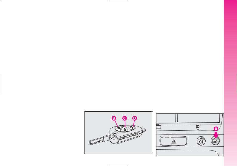
The remote control is incorporated in the key and it is fitted with buttons (B-C-D- fig. 6) that activate the corresponding control sending the code to the receiver. This code (rolling code) changes at each transmission.
REQUEST FOR ADDITIONAL KEYS WITH
REMOTE CONTROL
The receiver can recognise up to 5 keys with incorporated remote control. Should a new key with remote control be necessary for any reason during the life of the car, contact directly Alfa Romeo Authorised Services, taking with you the CODE card, a personal identity document and the car’s ownership documents.
A0A0601b
fig. 6
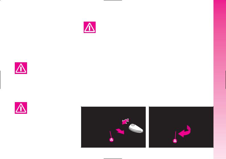
HOW TO ACTIVATE THE ALARM |
CAR |
|
With the doors, bonnet and boot shut and |
||
YOUR |
||
the ignition key in the STOP or PARK po- |
||
sition (key removed), point the key with the |
|
|
remote control in the direction of the car, then |
KNOW |
|
press and release the button (C-fig. 6). |
||
|
||
With the exception of certain markets, the |
|
|
system sounds a “beep” and the doors are |
TO |
|
locked. |
||
fig. 7) on the dashboard. If a fault is de- |
GETTING |
|
Engagement of the alarm is preceded by |
|
|
a self-diagnostic test indicated by a different |
|
|
flashing frequency of the deterrent led (A- |
|
|
tected the system sounds a further warn- |
|
|
ing “beep”. |
|
|
A0A0005b |
fig. 7 |
11 |
|

GETTING TO KNOW YOUR CAR
Surveillance
After switching on, the flashing of the deterrent led (A-fig. 7) on the dashboard indicates the system surveillance mode. The led flashes throughout this period.
IMPORTANT Operation of the electronic alarm is adapted at the origin to the rules of the different countries.
Self-diagnostic functions
and door, bonnet, boot control
If, after engaging the alarm, a second “beep” is sounded, switch off the system pressing the button (B-fig. 6), check that the doors, bonnet and tailgate are properly shut, then switch the system on again pressing the button (C). Otherwise, the door, bonnet or tailgate that is not shut properly will be excluded from the alarm system control.
If the doors, bonnet and boot are shut correctly and the control signal is repeated, the system self-diagnostic has detected a system operating fault. It is therefore necessary to contact Alfa Romeo Authorised Services.
HOW TO DEACTIVATE
THE ALARM
To deactivate the alarm press the button (B- fig. 6) of the key with remote control. The system will react as follows (with the exception of certain markets):
–two brief flashes of the direction indicators
–two brief “beeps” of the system
–door unlocking.
IMPORTANT If when the system is turned off the deterrent led (A-fig. 7) on the dashboard stays on (maximum 2 minutes or until the ignition key is set to MAR) the following should be borne in mind:
– if the led continues flashing, but at different intervals than normal, this means that different attempts to break in have occurred. Through the number of flashes it is possible to identify the type of attempt:
1 flash: |
one or more doors |
2 flashes: |
tailgate |
3 flashes: |
bonnet |
4 flashes: |
ultrasounds |
5 flashes: |
abnormal car lifting/slop- |
|
ing (for versions/markets |
|
where applicable) |
6 flashes: |
tampering with car starting |
|
cables |
7 flashes: |
tampering with battery ca- |
|
bles or cutting emergency |
|
key cables |
8 flashes: |
connection line to sensors |
|
and siren |
9 flashes: |
at least three causes of |
|
alarm. |
12

WHEN THE ALARM IS
TRIGGERED
When the system is on, the alarm comes into action in the following cases:
–opening of one of the doors, bonnet or tailgate;
–disconnection of the battery or sectioning of electric cables;
–intrusion in the passenger compartment, for example breakage of windows (volumetric protection);
–attempt to start the engine (key in MAR position);
–abnormal car lifting/sloping (for versions/markets where applicable).
Depending on the markets, the cutting in of the alarm causes operation of the siren and hazard warning lights (for about 26 seconds). The ways of operating and the number of cycles may vary depending on the markets.
A maximum number of cycles is however envisaged.
Once the alarm cycle has ended, the system resumes its normal control function.
VOLUMETRIC PROTECTION
To make sure that the protection system works correctly the side windows and sunroof (if fitted) must be properly shut.
The function can be cut off (if, for example, leaving animals in the car) carrying out the following operations in rapid succession: starting from the condition with the ignition key at MAR, move the key to STOP, then immediately back to MAR and then to STOP again, then remove the ignition key.
The deterrent led (A-fig. 7) on the dashboard lights up for about 2 seconds to confirm that the function has been cut off.
To restore volumetric protection, move the and keep the ignition key at MAR for over 30 seconds.
If, with the volumetric protection function deactivated, an electric control controlled by the ignition key at MAR (e.g. power windows) turn the ignition key to MAR, operate the control and move the key to STOP in a maximum time of 30 seconds. This way volumetric protection is not restored.
HOW TO CUT OFF
THE ALARM SYSTEM
To deactivate the alarm system completely (for instance during prolonged inactivity of the car) simply lock the car turning the key in the lock.
MINISTERIAL CERTIFICATION
In accordance with the law in force in each country, on the subject of radio frequency, we wish to point out that for the markets in which the transmitter needs to be marked, the certification number is given on the component.
Depending on the versions/markets, the code may also be given on the transmitter and/or on the receiver.
GETTING TO KNOW YOUR CAR
13
GETTING TO KNOW YOUR CAR
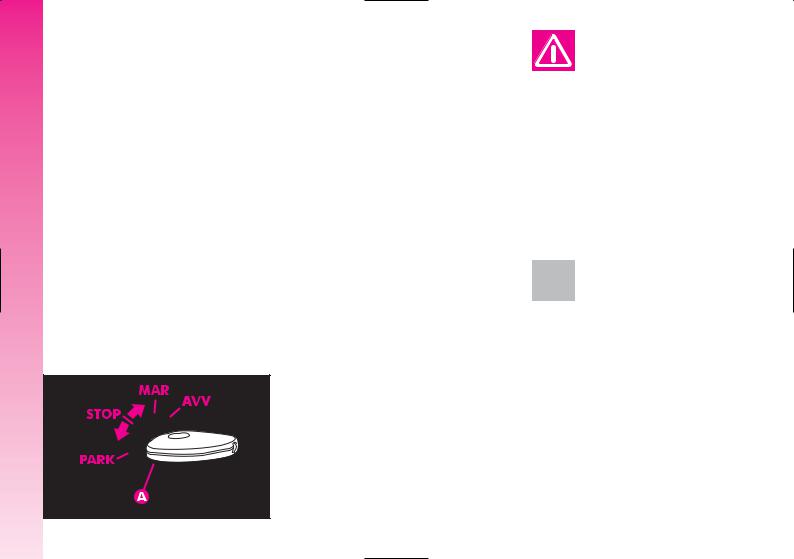
IGNITION DEVICE
SWITCH (fig. 8)
The key can be turned to one of four positions:
–STOP: engine switched off, key can be removed, engine inhibitor engaged, steering lock engaged, services excluded apart from those supplied directly (e.g. hazard warning lights).
–MAR: drive position. The engine lock is deactivated and all electrical devices are powered.
IMPORTANT Do not leave the key in this position when the engine is stopped.
– AVV: unstable position for starting the engine.
IMPORTANT If the engine fails to start move the key back to STOP and repeat.
The ignition switch has a safety device which prevents passage to AVV when the engine is running.
– PARK: engine switched off, key can be removed, engine lock engaged, steering lock engaged, sidelights switched on automatically.
IMPORTANT To turn the key to the PARK position, button (A) on the switch must be pressed first.
A0A0016b
When leaving the car always remove the key from the ignition to prevent any
occupants of the car from accidentally activating the controls. Never leave children in the car unaccompanied. Remember to engage the handbrake and, if the car is parked on an uphill slope, to engage the first gear. If the car is facing downhill, engage reverse gear.
If the ignition device is tampered with (for example an attempted theft)
have it checked over by Alfa Romeo Authorised Services before travelling again.
14 fig. 8
STEERING LOCK
Engaging:
– move the key to STOP or PARK, then remove the key and turn the steering wheel slightly to facilitate the locking action.
Disengaging:
– turn the key to MAR gently rocking the steering wheel from side to side.
Never remove the ignition key with the car on the move. The steering wheel
would lock automatically the first time the steering wheel is turned. This also occurs if the car is towed.
It is absolutely forbidden |
to carry out whatever af- |
ter-market operation in- |
volving steering system or steer- |
ing column modifications (e.g.: in- |
stallation of anti-theft device) that |
could badly affect performance and |
safety, cause the lapse of warran- |
ty and also result in non-compli- |
ance of the car with homologation |
requirements. |
DOORS
Before opening a door, always make sure that it can be done safely.
OPENING/CLOSING
FROM OUTSIDE
Front doors
–To open the door, turn the key (clockwise for the driver’s door and, upon request for versions/markets where applicable, counterclockwise for the passenger’s door), then remove the key and pull the lever (A-fig. 9).
–To close the door, turn the key in the lock in the opposite direction to the one for opening.
A0A0017b
fig. 9
OPENING/CLOSING |
CAR |
|
FROM INSIDE |
||
Front doors |
YOUR |
|
|
||
– To open the door, pull the handle |
KNOW |
|
(A-fig. 10). |
||
|
||
– To close the door, pull it; then to prevent |
|
|
opening from the outside, press the button |
TO |
|
(A-fig. 11) on the dashboard, the deter- |
||
rent led (B) on the button lights up with a |
GETTING |
|
yellow light to confirm that locking has tak- |
||
|
||
en place. |
|
A0A0018b
fig. 10 |
15 |
CAR |
CENTRAL LOCKING |
|
This allows central locking of the door |
||
YOUR |
||
locks. |
||
To engage central locking, the doors must |
||
KNOW |
be perfectly shut, otherwise locking is de- |
|
nied. |
||
IMPORTANT With central locking en- |
||
TO |
gaged, pulling the inside lever for opening |
|
one of the front doors causes the unlock- |
||
GETTING |
||
ing of all the doors. |
||
|
||
|
In the event of a power cut off (blown |
|
|
fuse, battery disconnected, etc.) it is still pos- |
|
|
sible to work the lock by hand. |
|
A0A0019b |
16 |
fig. 11 |
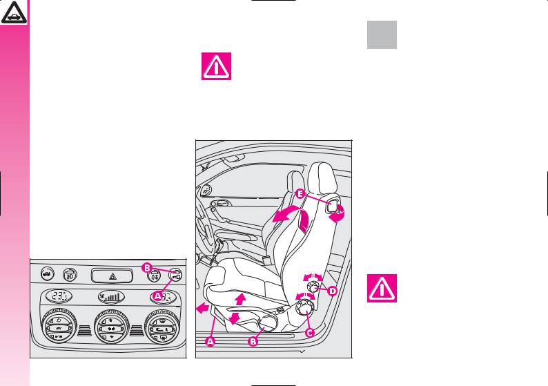
FRONT SEATS
Only make adjustments when the car is stationary.
A0A0602b |
fig. 12
Fabric upholstery of your car is purpose-made to withstand common wear resulting from normal use of the car. It is however absolutely necessary to prevent hard and/or prolonged scratching/scraping caused by clothing accessories like metallic buckles, studs, “Velcro” fixings, etc. that stressing locally the fabric could break yarns and damage the
upholstery as a consequence.
LENGTHWISE ADJUSTMENT
(fig. 12)
Raise the lever (A) and push the seat backwards or forwards; in the driving position the arms should be slightly flexed and the hands should rest on the rim of the steering wheel.
After releasing the adjustment lever, always check that the seat is
locked on the runners, trying to move it to and fro. The lack of this clamping action could cause the seat to move unexpectedly and cause loss of car control.
DRIVER’S SEAT LUMBAR
ADJUSTMENT (fig. 12)
Turn the knob (D) until obtaining the most comfortable position.
DRIVER’S SEAT HEIGHT
ADJUSTMENT (fig. 12)
To raise the seat, pull the lever (B) upwards, then work the lever (up and down) until reaching the required height, then release it. To lower the seat, push the lever (B) downwards, then work the lever (up and down) until reaching the required height.
IMPORTANT Adjustment must be carried out only seated in the driver’s seat.
TILTING THE BACK REST (fig. 12)
To gain access to the rear seats, pull the handle (E), the back rest folds and the seat is free to run forwards.
A recovery mechanism with memory makes it possible to take the seat back to its previous position.
Once the seat back has been returned to the travelling condition, make sure that it is correctly clamped, checking that the “red band” on the upper part of the handle (E) is concealed. In fact, this “red band” indicates that the seat back is not clamped.
Also check that the seat is firmly locked on the runners, trying to move it to and fro.
BACK REST ANGLE
ADJUSTMENT (fig. 12)
Turn the knob(C) until reaching the position required.
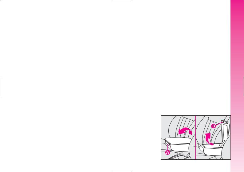
CENTRAL ARMREST |
(fig. 13) |
CAR |
|
|
|||
The armrest, fitted on some versions, is ad- |
YOUR |
||
justable and can be raised and lowered to |
|||
the required position. |
|
|
|
To adjust, slightly raise the armrest, then |
KNOW |
||
press the the release device (A). |
|||
|
|||
Inside the armrest there is an oddments |
TO |
||
compartment, to use it, raise the cover, |
|||
pressing the device (B). |
|
||
|
GETTING |
||
|
|
||
|
A0A0023b |
fig. 13 |
17 |
GETTING TO KNOW YOUR CAR
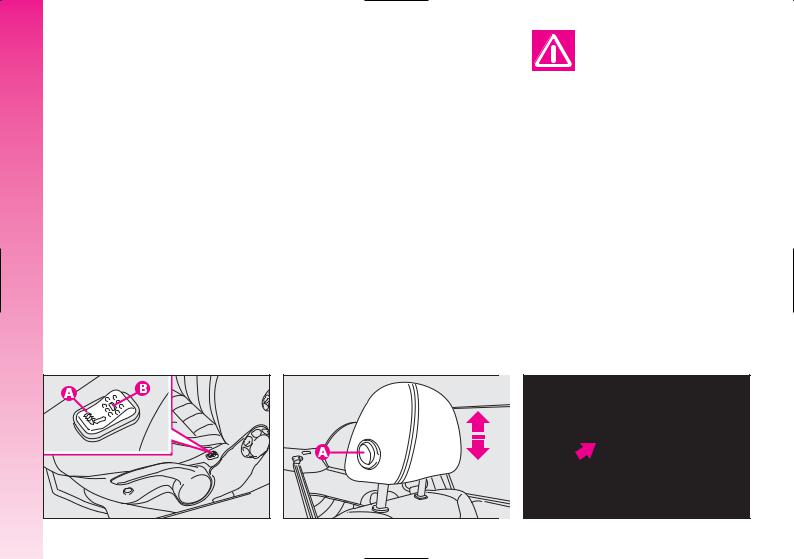
SEAT WARMING (fig. 14)
Seat warming, fitted on certain versions, is turned on and off through the switch (A) on the outer side of the seat.
Switching on is shown by the lighting up of the led (B) on the switch itself.
HEADREST ADJUSTMENT
(fig. 15)
To increase passengers’ safety, the headrests are adjustable in height.
To adjust, press the button (A) and move the headrest up or down until it clicks into place.
IMPORTANT The configuration of the headrest cushion may vary depending on the versions and markets. The purpose of the illustration is only to show how it is adjusted.
Remember that headrests should be adjusted so that the nape, and not the neck,
rests on them. Only in this position do they exert their protective action in the event of a crash from behind.
REAR POCKETS (fig. 16) (for versions/markets where applicable)
The front seats are fitted with a pocket in the rear of the back rest.
|
A0A0024b |
18 |
fig. 14 |
A0A0604b |
A0A0026b |
fig. 15 |
fig. 16 |
REAR SEATS
Fabric upholstery of your car is purpose-made to withstand common wear resulting from normal use of the car. It is however absolutely necessary to prevent hard and/or prolonged scratching/scraping caused by clothing accessories like metallic buckles, studs, “Velcro” fixings, etc. that stressing locally the fabric could break yarns and damage the
upholstery as a consequence.
EXTENDING THE LUGGAGE COMPARTMENT
The split of rear seat makes it possible to extend the luggage compartment totally or partially, acting separately on one of the two parts, thereby offering different possibilities of load depending on the number of rear passengers.
If a particularly heavy load is placed in the boot, when travelling at night, it
is wise to check the height of the high beams (see “Headlamps” paragraph).
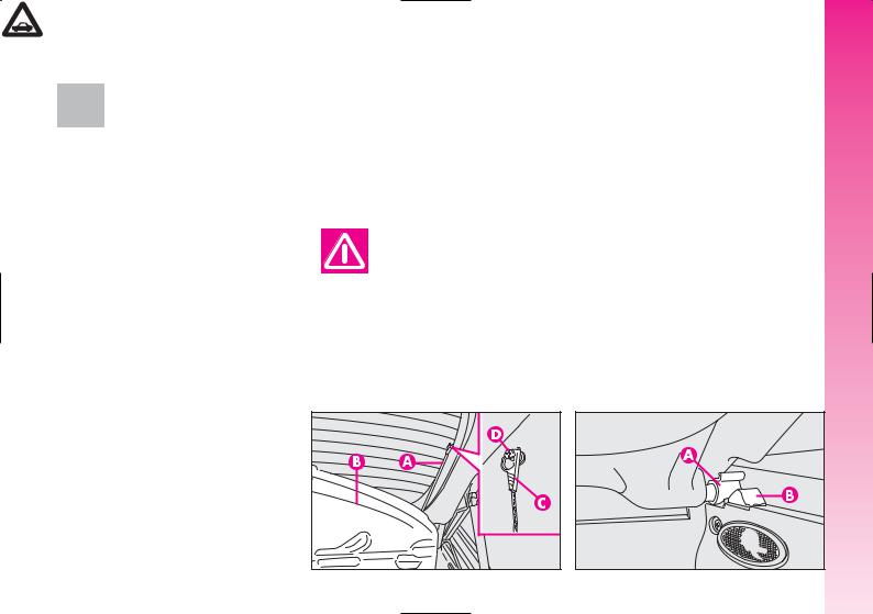
Removing the rear parcel shelf
Proceed as follows:
–free the ends of the two rods (A-fig. 18) supporting the parcel shelf (B) pulling the eyelets (C) off the pins (D);
–release the pins (A-fig. 19) at the outside of the shelf from their housings (B) obtained in the side supports, then remove the shelf pulling it outwards.
GETTING TO KNOW YOUR CAR
A0A0605b |
fig. 18 |
|
A0A0255b |
fig. 19 |
19 |
GETTING TO KNOW YOUR CAR
Total extension
Proceed as follows:
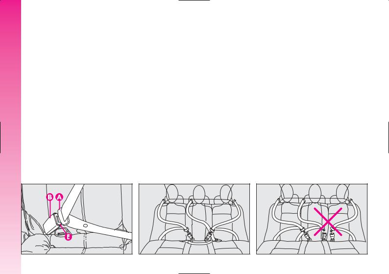
–check that seat buckles of the side belts are fitted in the respective pockets on the back rest (A-fig. 20) and the tab (B) of the centre abdominal belt is inserted in the support (C).
–pull the handles in the centre of the cushions, then tilt them forwards;
–raise the headrest to the highest position, press both buttons (A-fig. 21) at the side of the two supports, then remove the headrest pulling them upwards;
–move the seat belts to the side extending them correctly without twisting;
–raise the levers (A-fig. 22) retaining the back rests and tilt them forwards to obtain a single loading surface (fig. 23).
|
A0A0623b |
20 |
fig. 20 |
A0A0607b |
fig. 21
IMPORTANT For versions/markets where applicable, the retainer levers are replaced by buttons (one for each side). To release the back rests and tilt them, use the buttons themselves.
A0A0608 b
fig. 22
A0A0608 b |
fig. 23
Partial extension
For partial extension, proceed as follows:
–tilt the cushion required pulling the handle at the centre of the cushion, then tilting the actual cushion;
–move the seat belt to one side extending it correctly without twisting;
–raise the lever retaining the back rest and tilt it forwards.
To bring the seat back to its normal position
Proceed as follows:
–move the seat belts to one side extending them correctly without twisting;
–raise the seat backs, pushing them backwards until hearing both clamping devices click into place;
–set the cushions to the horizontal position keeping the centre seat belt raised.
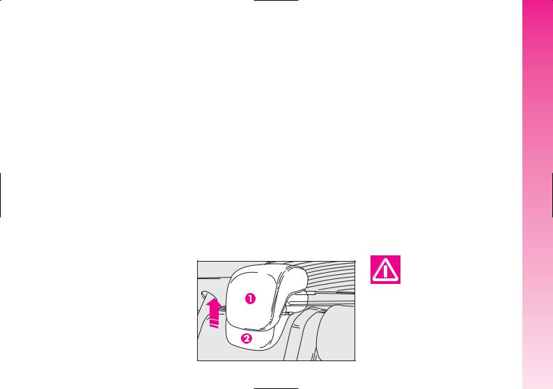
HEADREST ADJUSTMENT
(fig. 24)
The car may be fitted with two headrests for the side seats and, depending on the trim level, it may also have a third headrest in the centre.
To use the headrest, raise it from the (2) “non use position” and reach the (1) “all removed” position. To restore the “non use position”, press button (A-fig. 21) and push the headrest downwards.
All rear headrests can be removed.
A0A0610b |
fig. 24
The particular headrest shape interferes intentionally with the rear passenger’s correct position on the back rest; this forces the passenger to raise the headrest to use it correctly.
IMPORTANT When using rear seats, the headrests shall be kept in the “all removed” position.
Remember that headrests should be adjusted so that the nape, and not the neck,
rests on them. Only in this position do they exert their protective action in the event of a crash from behind.
GETTING TO KNOW YOUR CAR
21
GETTING TO KNOW YOUR CAR
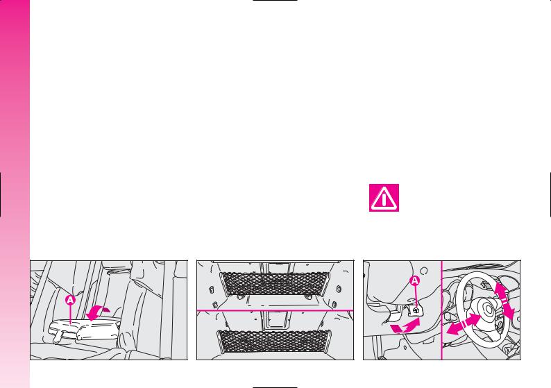
CENTRAL ARMREST (fig. 25)
To use the armrest (A), present only on certain versions, lower it as illustrated.
LUGGAGE RETAINER NET (where provided)
Present only on certain versions, the retainer net (fig. 26) is helpful in correctly arranging the load and/or suitable for transporting light materials.
STEERING WHEEL
The driver can adjust the steering wheel position in rake and height.
To do this, release the lever (A-fig. 27) pulling it towards the steering wheel.
After moving the steering wheel to the most suitable position, lock it pushing the lever fully forwards.
Any adjustment of the steering wheel position must be carried out only
with the car stationary.
|
|
A0A0611b |
A0A0624b |
A0A0706b |
22 |
fig. 25 |
fig. 26 |
|
fig. 27 |
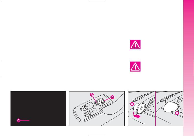
REAR-VIEW MIRROR ADJUSTMENT
INNER
The mirror, fitted with a safety device that causes it to be released in the event of a violent crash, can be moved using the lever (A-fig. 28) to two different positions, normal or antiglare.
OUTER
Electric adjustment (fig. 29)
–use the switch (A) to select the mirror required (right or left);
–pressing the button (B) in one of the four directions, move the mirror selected previously;
–position the switch (A) in the intermediate locking position.
IMPORTANT Adjustment is possible only with the ignition key at MAR.
Folding (fig. 30)
– In the event of need (for example when the mirror causes difficulty in narrow spaces) it is possible to fold the mirror moving it from position (A) to position (B).
When driving the mirrors should always be in position (A).
As the driver’s wing mirror is curved, it may slightly alter the perception of
distance.
GETTING TO KNOW YOUR CAR
A0A0039b |
A0A0040b |
A0A0041b |
fig. 28 |
fig. 29 |
fig. 30 |
23 |
GETTING TO KNOW YOUR CAR
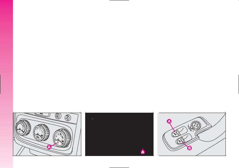
Defrosting/demisting (fig. 31-32)
The electric mirrors are fitted with heating coils which come into operation with rearscreen heating pressing the button (A) thereby defrosting and/or demisting the mirrors.
IMPORTANT The function is timed and automatically switched off after a few minutes.
POWER WINDOWS
IMPORTANT With the ignition key at STOP or removed, the power windows remain activated for about 3 minutes and are deactivated immediately the moment a door is opened.
Driver’ side (fig. 33)
The driver’s door panel contains the buttons that control the following windows, with the ignition key at MAR:
A - left front window B - right front window.
Press the button to lower the window. Pull to raise it.
A0A0042b |
A0A0612b |
A0A0043b |
24 fig. 31 |
fig. 32 |
fig. 33 |
IMPORTANT The driver’s power window is fitted with the “continuous automatic operation” device for both lowering and raising the window. A brief press on the upper or lower part of the button will cause it to move and continue automatically: the window stops in the required position by pressing either the upper or lower part of the button again. The passenger window is fitted with “automatic continuous operation” device just for window opening.
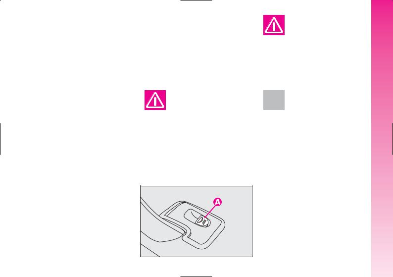
Passenger’s side (fig. 34)
The button (A) controls the passenger’s side window.
Button and window operation is the same as that described for driver’s side.
Improper use of the power windows can be dangerous. Before and during its
operation, always make sure that passengers are not exposed to the risk of harm either directly by the moving windows or by personal objects drawn or knocked by them.
Always remove the ignition key when getting out of the car to prevent the
power windows being operated accidentally and constituting a danger to the passengers in the car.
Do not keep the button pressed when the window is completely raised or
lowered.
GETTING TO KNOW YOUR CAR
A0A0044b
fig. 34 |
25 |

GETTING TO KNOW YOUR CAR
For all versions, after unlocking the doors, keeping the remote control button pressed for about 2 seconds will obtain window opening.
IMPORTANT For versions/markets where applicable, after turning off control unit power (replacing or disconnecting the battery or replacing the power window control unit protection fuses), window automatism shall be restored.
Proceed as follows with doors closed:
1.open completely the driver’s window keeping the button pressed for at least 3 seconds after full opening;
2.close completely the driver’s window keeping the button pressed for at least 3 seconds after full closing;
3.proceed as described in points 1 and 2 also for the passenger’s side;
4.check for proper initialisation by operating the windows in automatic.
SEAT BELTS
USING THE SEAT BELTS
The belt should be worn keeping the chest straight and rested against the seat back.
To fasten the seat belts: hold the tongue (A-fig. 35) and insert it into the buckle (B), until hearing the locking click. At removal, if it jams, let it rewind for a short stretch, then pull it out again without jerking.
A0A0045b
26 |
fig. 35 |
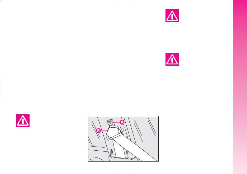
To unfasten the seat belts: press button (C-fig. 35). Guide the seat belt with your hand while it is rewinding, to prevent it from twisting. Through the reel, the belt automatically adapts to the body of the passenger wearing it, allowing freedom of movement.
When the car is parked on a steep slope the reel mechanism may block; this is normal. The reel mechanism prevents the webbing coming out when it is jerked or if the car brakes sharply, in a collision or when cornering at high speed.
FRONT SEAT BELT HEIGHT ADJUSTMENT
Always adjust the height of the belts adapting it to the person who is wearing it. This precaution improves their effectiveness substantially reducing the risk of injury in the event of a crash.
Correct adjustment is obtained when the belt passes half way between the end of the shoulder and the neck.
The front seat belt ring can take 4 different positions which make it possible to adjust the height of the belts.
To adjust, press button (A-fig. 36) and lower or raise the grip (B).
Always adjust the seat belt height when the car is stationary.
After adjustment, always check that the slider is anchored in one of the posi-
tions provided. To do this, with the button (A) released, exert a further pressure to allow the anchor device to catch if release did not take place at one of the preset positions.
GETTING TO KNOW YOUR CAR
Never press button (C) when travelling.
|
A0A0685b |
fig. 36 |
27 |
GETTING TO KNOW YOUR CAR
REAR BELTS
To fasten the belt: gently pull the belt from its reel and guide the tape to prevent it from twisting, then insert the tongue (A-fig. 37) into the buckle housing (B).
To unfasten the seat belts, press button (E).
Rear seat belts shall be worn as shown in fig. 38. Fig. 39 shows improper belt fastening. To tilt the back rest see paragraph “Boot extension”.
IMPORTANT The centre rear seatbelt is installed on request only for versions/markets on which it is required.
IMPORTANT Remember that, in the event of an accident, any passengers occupying the rear seats who are not wearing a seat belt not only subject themselves to great personal risk, but constitute a danger to the occupants of the front seats.
PRE-TENSIONING DEVICES
To increase the efficiency of the front seat belts, the car is fitted with pre-tensioning devices. These devices “feel” that the car is being subject to a violent impact by way of a sensor and rewind the seat belts a few centimetres. In this way they ensure that the seat belt adheres to the wearer before the restraining action begins.
The seat belt locks to indicate that the device has intervened; the seat belt cannot be drawn back up even when guiding it manually.
IMPORTANT The pretensioner will give maximum protection when the seat belt adheres snugly to wearer’s chest and hips.
A0A0686b |
A0A0386b |
A0A0387b |
28 fig. 37 |
fig. 38 |
fig. 39 |
Pretensioner activation may produce a small amount of smoke. This smoke is in no way toxic and presents no fire hazard.
The emergency tensioning retractor needs no maintenance or lubrication. Any modification to its original features will nullify the retractor effectiveness. If, due to unusual natural events (floods, high waves, etc.), the device has been affected by water and mud, it must be replaced.
Pre-tensioning devices can only be used once. After they have been triggered
contact Alfa Romeo Authorised Services to have them replaced. The validity of the device is 10 years from the date of production on the sticker; the pretensioners should be changed at an Alfa Romeo Authorised Service as this date approaches.
Operations involving banging, vibrations or heating (above 100°C for a maximum of 6 hours) in the area of the
pretensioners may damage or trigger off the device. Vibrations from rough road surfaces or accidental jolting caused by mounting pavements etc. do not have any effect on the pretensioner. If, however, you need assistance, go to Alfa Romeo Authorised Services.
LOAD LIMITERS
To increase passengers’ protection in the event of an accident, the front and rear (where provided) seat belt reels contain a load limiter which allows controlled sag in such a way as to dose the force acting on the shoulders and chest during the belt restraining action in case of a crash.
GENERAL INSTRUCTIONS |
CAR |
|
FOR THE USE OF THE SEAT |
||
BELTS |
YOUR |
|
All the occupants of the car are obliged to |
||
|
||
respect the local traffic laws regarding the |
KNOW |
|
wearing of seat belts. |
||
|
||
Always fasten the seat belts before starting. |
TO |
|
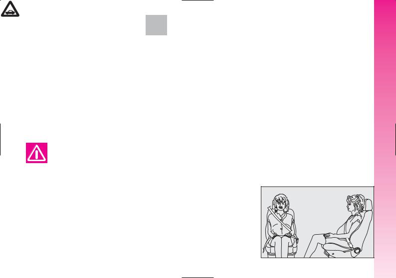
Seat belts are also to be worn by expec- |
||
|
||
tant mothers: the risk of injury in the case |
GETTING |
|
of accident is greatly reduced for them and |
||
|
||
the unborn child if they are wearing a seat |
|
|
belt. Pregnant women must of course posi- |
|
|
tion the lower part of the belt very low down |
|
|
so that it passes under the abdomen (as il- |
|
|
lustrated in fig. 40). |
|
A0A0675b
fig. 40 |
29 |
 Loading...