


Dear Customer,
thank you for choosing Alfa Romeo.
Your Alfa 159 has been designed to guarantee the safety, comfort and driving pleasure typical of Alfa Romeo.
This booklet will help you to get to know the characteristics and operation of your car.
The following pages contain all the indications necessary for you to be able to maintain the high standards of performance, quality, safety and respect for the environment which characterize this Alfa 159.
The enclosed Warranty Booklet also contains the regulations, the warranty certificate and a guide to the services offered by Alfa Romeo.
Services which are essential and precious because, when you purchase an Alfa Romeo you are not only acquiring a car, but the tranquillity that comes from knowing that an efficient, willing and widespread organization is at your service for any assistance problems you may have.
Have a good trip.
This booklet describes all the versions of the Alfa 159, so you should only consider the information concerning the trim level, engine and version purchased by you.

MUST BE READ!
REFUELLING
K |
Petrol engines |
: only refuel with unleaded petrol with octane rating (RON) not less than 95. |
Diesel engines |
: only refuel with diesel fuel conforming to the European specification EN590. The use of |
|
|
other products or |
mixtures may irreparably damage the engine with invalidation of the warranty due to the |
|
damage caused. |
|
ENGINE STARTING
Petrol engines: ensure that the handbrake is up, fully press the clutch pedal, without pressing the accelerator, put the gear lever neutral, fit the electronic key into the ignition device to stop limit, briefly press the START/STOP button.
Diesel engines: ensure that the handbrake is up, fully press the clutch pedal, without pressing the accelerator, put the gear lever neutral, fit the electronic key down into the ignition device until it stops. The instrument panel warning light m will turn on, wait for the warning light m to turn off. The hotter the engine is, the quicker this will happen, briefly press the START/STOP button as soon as the warning light m turns on.
PARKING ON FLAMMABLE MATERIAL
While working, the catalyst develops a very high temperature. Do not park the car over grass, dry leaves, pine needles or any other inflammable materials: risk of fire.
RESPECTING THE ENVIRONMENT
A system for continuously monitoring emission system components to ensure greater environmental protection is fitted in your car.

ELECTRICAL ACCESSORIES
|
If, after buying the car, you decide to add electrical accessories (that will gradually drain the battery), contact Al- |
fa Romeo Authorized Services. They can calculate the overall electrical requirement and check that the car’s elec- |
|
tric system can support the required load. |
CODE CARD (for version/markets where applicable)
Keep the code card in a safe place, not in the car.
SCHEDULED SERVICING
Correct maintenance of the car is essential for ensuring it stays in tip-top condition and safeguards its safety features, its environmental friendliness and low running costs for a long time to come.
THE OWNER’S MANUAL CONTAINS…
…information, tips and important warnings regarding the safe, correct driving of your car, and its maintenance. Pay particular attention to the symbols " (personal safety) # (environmental protection) â (car well-be- ing).

Any queries concerning servicing should be forwarded to the showroom from which the car was purchased, the subsidiary company or to our branch offices or any point of the Alfa Romeo Network.
Warranty Booklet
The Warranty Booklet is delivered together with every new car and contains the regulations tied to the services given by Alfa Romeo Services and to the warranty conditions.
Correctly carrying out the scheduled services specified by the manufacturer is the best way to maintain the performance, safety characteristics and low running costs of your car. It is also necessary to maintain warranty cover.
“Service” guide
This contains the Alfa Romeo Authorized Services. The services can be recognized by the presence of the Alfa Romeo badge and logo.
The Alfa Romeo organization in Italy can be found in the telephone book under the letter “A” Alfa Romeo.
Not all the models described in this booklet are available in all countries. Only some of the fittings described in this booklet are fitted as standard to the car. The list of available accessories should be requested from the Alfa Romeo Dealers.
THE SYMBOLS USED IN THIS BOOKLET
The symbols illustrated in these pages show the subjects which should, in particular, be closely studied.
PERSONAL |
PROTECTING THE |
|
SAFETY |
ENVIRONMENT |
CAR SAFETY |
Warning: partially or |
This indicates the correct procedures |
fully ignoring these rules may lead |
to be followed to prevent |
to serious injury. |
the car from damaging the environment. |
Warning: partially or fully ignoring these rules may lead to serious damage
being caused to the car which, in some circumstances, may cause forfeiture of the warranty cover.
The texts, illustrations and specifications given in this booklet refer to the car at the time of going to press.
As part of our ongoing striving to improve our products, Alfa Romeo may introduce technical changes during production, therefore the specifications and fittings may be altered without prior notice.
For details on this subject, please apply to the manufacturer's sales network.

DASHBOARD |
AND |
CONTROLS |
|
SAFETY |
DEVICES |
|
CORRECT USE |
OF THE CAR |
WARNING |
LIGHTS AND |
MESSAGES |
|
IN AN |
EMERGENCY |
|
CAR |
MAINTENANCE |
|
TECHNICAL |
SPECIFICATIONS |
|
|
INDEX |
DASHBOARD AND CONTROLS
DASHBOARD .................................................... |
7 |
INSTRUMENT PANEL ......................................... |
8 |
SYMBOLS ....................................................... |
9 |
ALFA ROMEO CODE SYSTEM ............................... |
9 |
ELECTRONIC KEY .............................................. |
11 |
ALARM ........................................................... |
17 |
IGNITION DEVICE............................................... |
19 |
INSTRUMENTS .................................................. |
21 |
MULTIFUNCTION DISPLAY ................................... |
25 |
RECONFIGURABLE MULTIFUNCTION DISPLAY .......... |
30 |
SEATS ............................................................ |
45 |
HEAD RESTRAINTS............................................. |
48 |
STEERING WHEEL ............................................. |
49 |
REARVIEW MIRRORS ......................................... |
50 |
CLIMATE CONTROL SYSTEM ............................... |
53 |
MANUAL CLIMATE CONTROL SYSTEM ................... |
55 |
AUTOMATIC TWO-/THREE-ZONE |
|
CLIMATE CONTROL SYSTEM ............................... |
58 |
ADDITIONAL HEATER ......................................... |
69 |
EXTERNAL LIGHTS ............................................. |
70 |
WINDOW WASHING ......................................... |
73 |
CRUISE CONTROL ............................................. |
76 |
CEILING LIGHTS ................................................ |
78 |
CONTROLS ....................................................... |
81 |
INTERIOR FITTINGS............................................ |
83 |
SUNROOF ........................................................ |
93 |
DOORS ........................................................... |
96 |
POWER WINDOWS ........................................... |
99 |
BOOT .............................................................. |
101 |
BONNET .......................................................... |
105 |
ROOF RACK/SKI RACK ...................................... |
106 |
HEADLIGHTS..................................................... |
106 |
ABS SYSTEM ................................................... |
108 |
VDC SYSTEM ................................................... |
110 |
EOBD SYSTEM ................................................. |
115 |
SOUND SYSTEM PRESETTING .............................. |
116 |
ACCESSORIES PURCHASED BY THE OWNER .......... |
116 |
INSTALLATION OF ELECTRIC/ELECTRONIC DEVICES .. |
117 |
PARKING SENSORS ........................................... |
118 |
TYRE PRESSURE MONITORING SYSTEM |
|
(T.P.M.S.) ........................................................ |
122 |
AT THE FILLING STATION .................................... |
125 |
PROTECTING THE ENVIRONMENT ........................ |
127 |
6
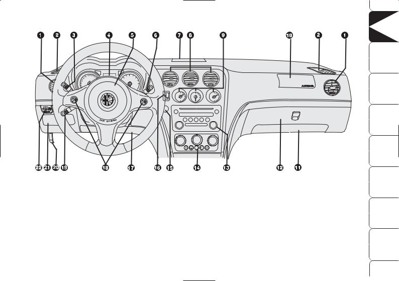
DASHBOARD
fig. 1 |
A0E0056m |
|
1. Adjustable swivel side air vents - 2. Front side window demisting/defrosting vents - 3. External lights control lever - 4. Instrument panel - 5. Driver’s air bag and horn - 6. Windscreen wiper control lever - 7. Upper central vent - 8. Adjustable swivel centre air vents - 9. Fuel level gauge/engine coolant temperature gauge/engine oil temperature gauge (petrol versions) or turbocharger pressure gauge (diesel versions) - 10. Passenger’s air bag - 11. Passenger’s knees air bag (where provided) - 12. Glove box - 13. Sound system (where provided) - 14. Heating/ventilation/climate controls - 15. Engine START/STOP button - 16. Ignition device - 17. Driver’s knees air bag - 18. Sound system controls on the steering wheel (where provided) - 19. Cruise Control lever (where provided) - 20. Bonnet opening lever - 21. Dashboard fusebox lid - 22. Switches for external lights, trip meter reset and headlamp aiming device.
DASHBOARD |
AND CONTROLS |
SAFETY |
DEVICES |
CORRECT USE |
OF THE CAR |
WARNING LIGHTS |
AND MESSAGES |
IN AN |
EMERGENCY |
CAR |
MAINTENANCE |
TECHNICAL |
SPECIFICATIONS |
INDEX |
|
7
DASHBOARD AND |
CONTROLS |
SAFETY |
DEVICES |
CORRECT USE |
OF THE CAR |
WARNING LIGHTS |
AND MESSAGES |
IN AN |
EMERGENCY |
CAR |
MAINTENANCE |
TECHNICAL |
SPECIFICATIONS |
|
INDEX |
|
8 |
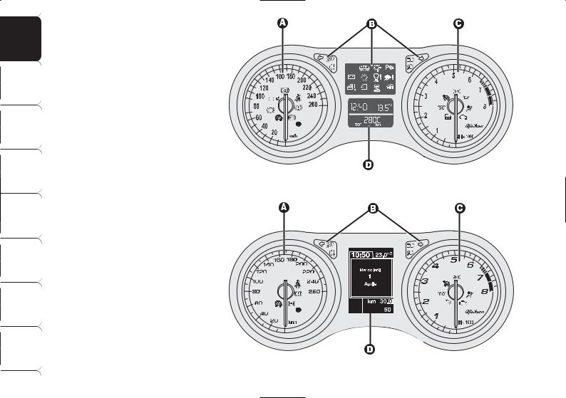
INSTRUMENT PANEL
A.Speedometer (speed indicator)
B.Warning lights - C. Rev counter -
D.Multifunction display
h c m Warning lights on diesel versions only
On diesel versions the rev counter end scale value is at 6000 rpm.
A.Speedometer (speed indicator)
B.Warning lights - C. Rev counter -
D.Reconfigurable multifunction display
c m Warning lights on diesel versions only
On diesel versions the rev counter end scale value is at 6000 rpm.
fig. 2 - Versions with multifunction display
fig. 3 - Versions with reconfigurable multifunction display
A0E0312m
A0E0422m

SYMBOLS
Special coloured labels have been attached near or actually on some of the components of your car. These labels bear symbols that remind you of the precautions to be taken as regards that particular component.
The plate summarising the symbols used fig. 4 can be found under the bonnet.
fig. 4 |
A0E0138m |
|
ALFA ROMEO
CODE SYSTEM
To further protect you car from theft, it has been fitted with an engine immobilising system. This system is automatically activated when the electronic key is removed.
An electronic device, in fact, is fitted in each electronic key grip. The device transmits a radio-frequency signal when the engine is started through a special aerial built into the ignition switch on the dashboard. The modulated signal, which changes each time the engine is started, is the “password”, by means of which the control unit recognises the electronic key and enables to start the engine.
DASHBOARD |
AND |
CONTROLS |
SAFETY |
DEVICES |
|
CORRECT USE |
OF THE CAR |
|
WARNING |
LIGHTS AND |
MESSAGES |
IN AN |
EMERGENCY |
|
CAR |
MAINTENANCE |
|
TECHNICAL |
SPECIFICATIONS |
|
INDEX |
|
|
9
DASHBOARD |
AND |
CONTROLS |
|
SAFETY |
DEVICES |
|
CORRECT USE |
OF THE CAR |
WARNING |
LIGHTS AND |
MESSAGES |
|
IN AN |
EMERGENCY |
|
CAR |
MAINTENANCE |
|
TECHNICAL |
SPECIFICATIONS |
|
|
INDEX |
OPERATION
Each time the electronic key is fitted into the ignition switch, the Alfa Romeo CODE system control unit sends a recognition code to the engine control unit to deactivate the inhibitor.
The code is sent only if the Alfa Romeo CODE system control unit has recognised the code transmitted from the electronic key.
If the code has not been recognised correctly, the warning light Yturns on (on certain versions a dedicated message is displayed) (see section “Warning lights and messages”).
In this case, the electronic key should be removed from the ignition device and then refitted; if the lock continues, possibly try again with the other keys provided with the car. If it is still not possible to start the car contact Alfa Romeo Authorized Services
Warning light Y coming on when driving
If the warning light Y turns on this means that the system is running a selftest (for example for a voltage drop).
If the warning light Ystays on, contact Alfa Romeo Authorized Services.
IMPORTANT Every electronic key has its own code, which must be memorised by the system control unit. To memorise new keys, up to a maximum of eight, apply solely to Alfa Romeo Authorized Services taking with you all the keys in your possession, the CODE card, a personal identity document and the car’s possession documents. The codes of the keys not provided during the new memorising procedure are erased from the memory. This is to ensure that any lost or stolen keys can no longer be used to start the car.
The electronic components inside the key may be damaged if the key is
submitted to sharp knocks.
If 2 seconds after fitting the electronic key into the ignition switch, the
warning light Y comes on again flashing (on certain versions a dedicated message is displayed), this means that the code of the keys has not been memorised, thus the car is not protected by the Alfa Romeo CODE system against attempted theft. In this case, contact an Alfa Romeo Authorized Service to have the key codes memorised.
10
ELECTRONIC KEY
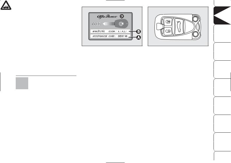
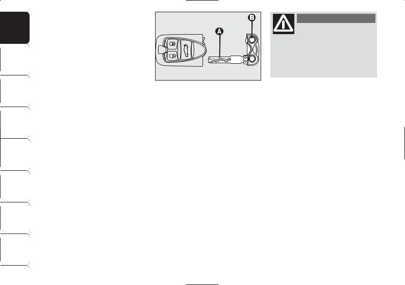
CODE CARD
(for versions/markets where applicable)
The CODE card fig. 5 delivered with the keys, contains the mechanical code A and the electronic one B.
The code numbers on the CODE card must be kept in a safe place, not in the car.
If the car changes owner, the new owner must be given the electronic
key and the CODE card.
fig. 5 |
A0E0023m |
|
ELECTRONIC KEY fig. 6
The car is delivered with two copies of the key with remote control.
The electronic key operates the ignition switch.
Button Á shall be used for central locking of doors, tailgate and fuel cap with alarm activation (where provided).
fig. 6 |
A0E0021m |
|
Button Ëshall be used for central opening of doors and fuel cap with alarm deactivation (where provided).
Button `shall be used to open the tailgate.
When unlocking the doors by pressing button Ë, if by 2.5 minutes no door or the boot is opened, the system will automatically lock the car again.
DASHBOARD |
AND CONTROLS |
SAFETY |
DEVICES |
CORRECT USE |
OF THE CAR |
WARNING LIGHTS |
AND MESSAGES |
IN AN |
EMERGENCY |
CAR |
MAINTENANCE |
TECHNICAL |
SPECIFICATIONS |
INDEX |
|
11
DASHBOARD AND |
CONTROLS |
SAFETY |
DEVICES |
CORRECT USE |
OF THE CAR |
WARNING LIGHTS |
AND MESSAGES |
IN AN |
EMERGENCY |
CAR |
MAINTENANCE |
TECHNICAL |
SPECIFICATIONS |
|
INDEX |
The electronic key fig. 7 is fitted with a metal insert A, that can be extracted by pressing button B.
The metal insert operates the following:
central door locking/unlocking through the driver's door lock (with run-down car battery only the driver's door will open);
windows opening/closing;
switch (where provided) for deactivating the passenger’s air bag and knees air bag (where provided);
safe-lock device (where provided);
emergency unlocking of electronic key from ignition switch.
fig. 7 |
A0E0022m |
|
IMPORTANT Never expose the electronic key to direct sunlight: risk of damages.
IMPORTANT Remote control frequency may be disturbed by radio transmissions outside the car (e.g. mobile phones, hams, etc…). In this event remote control may be failing.
WARNING
Never leave the electronic key unattended to prevent anyone, especially
children, from holding it and pressing button B-fig. 7 inadvertently.
12
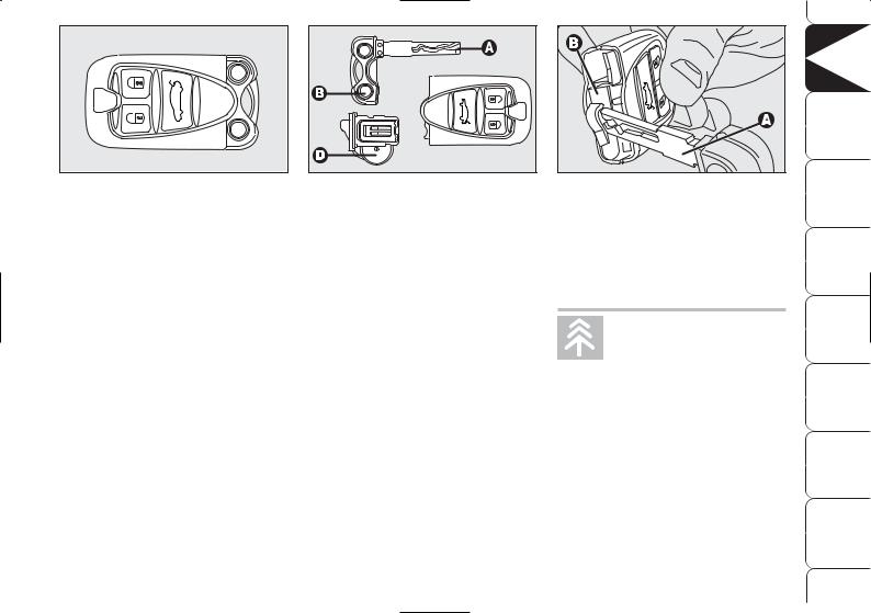
fig. 8 |
A0E0021m |
|
Replacing the battery of the electronic key
If when pressing button Ë, Á, or `, control given is refused or failing, the battery should be replaced with an equivalent one that can be purchased at common stores.
To be sure that the battery is to be replaced, try again to press buttons Ë, Á, or `with another electronic key.
When closing the tailgate again, protection sensors are restored and direction indicators will flash once.
fig. 9 |
A0E0035m |
|
To change the battery fig. 9 proceed as follows:
take out the metal insert A by pressing button B;
remove the snap-fitted case B- fig. 10 (red) by levering with the metal insert A of the electronic key in the point shown in the figure;
remove the battery D-fig. 9 from the case taking note of the bias (in the figure the positive pole is facing downwards);
put the new battery into the case with the correct bias;
put the case down into its seat and refit the metal insert.
|
|
|
|
|
DASHBOARD |
AND |
CONTROLS |
|
|
|
|
|
SAFETY DEVICES |
|
|
fig. 10 |
|
|
|
A0E0242m |
CORRECT USE OF THE CAR |
|
|
|
|
|
|
|
|||
IMPORTANT Never touch the electric |
|
||||||
contacts of the key and prevent fluid or |
WARNING LIGHTS |
AND MESSAGES |
|
||||
dust infiltration inside it. |
|
|
|
||||
|
|
|
|
|
|
||
|
Used |
batteries |
are |
IN AN |
EMERGENCY |
|
|
|
harmful to the environ- |
|
|||||
|
ment. They should be |
|
|||||
|
|
|
|
||||
disposed of as specified by law |
|
MAINTENANCE |
|
||||
in the special containers pro- |
CAR |
|
|||||
vided, |
or take them |
to |
Alfa |
|
|||
Romeo |
Authorized |
Services |
|
||||
|
SPECIFICATIONS |
|
|||||
which will deal with their dis- |
TECHNICAL |
|
|||||
posal. |
|
|
|
|
|
||
|
|
|
|
|
|
||
|
|
|
|
|
INDEX |
|
|
|
|
|
|
|
13 |
|
|

DASHBOARD AND |
CONTROLS |
SAFETY |
DEVICES |
CORRECT USE |
OF THE CAR |
WARNING LIGHTS |
AND MESSAGES |
IN AN |
EMERGENCY |
CAR |
MAINTENANCE |
TECHNICAL |
SPECIFICATIONS |
|
INDEX |
SAFE LOCK DEVICE (where provided)
This safety system inhibits the operation of the car door handles.
The safe lock device represents top protection against break in attempts. Activate it each time you park the car.
WARNING
Once the safe lock device has been actuated, doors cannot be opened from
inside the car in any way whatsoever. For this reason, make sure there are no persons left inside the car.
WARNING
If the key battery is flat, the safe lock device can only be deactivated by
unlocking the doors by turning the metal insert of the key into the driver’s door lock or by fitting the key into the ignition device.
WARNING
If the car battery is down, the safe lock device can be activated only us-
ing the metal insert of the electronic key on the driver’s door revolving plug: in this case the safe lock device is active on front passenger’s door and rear doors.
14
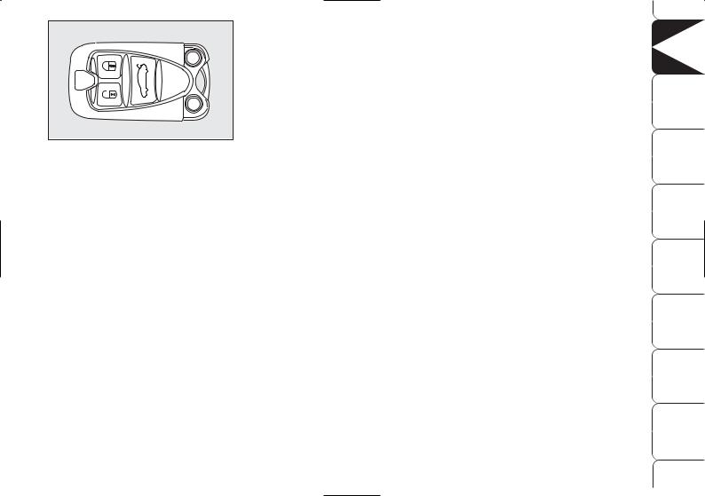
fig. 11 |
A0E0021m |
|
Device activation
The device is automatically activated on every door in the following cases:
turning twice the metal insert of the electronic key into the driver door to locking position;
pressing twice the electronic key button Á.
Device activation is signalled by three flashes of the led on the driver’s door panel and, only if activated by pressing the electronic key button Á, of direction indicators.
Should one of the doors be not perfectly closed, the safe lock device is not activated, thus preventing that a person getting into the car from the open door remains blocked inside the passenger’s compartment when he/she closes the door.
Device deactivation
The device is deactivated automatically on every door in the following cases:
when unlocking the doors;
when unlocking only the driver’s door (where possible);
when fitting the electronic key into the ignition switch.
DASHBOARD |
AND CONTROLS |
SAFETY |
DEVICES |
CORRECT USE |
OF THE CAR |
WARNING LIGHTS |
AND MESSAGES |
IN AN |
EMERGENCY |
CAR |
MAINTENANCE |
TECHNICAL |
SPECIFICATIONS |
INDEX |
|
15

DASHBOARD AND |
CONTROLS |
SAFETY |
DEVICES |
CORRECT USE |
OF THE CAR |
WARNING LIGHTS |
AND MESSAGES |
IN AN |
EMERGENCY |
CAR |
MAINTENANCE |
TECHNICAL |
SPECIFICATIONS |
|
INDEX |
16
The main functions that can be activated with the electronic key or with the emergency metals insert are the following:
|
|
Doors, |
|
Doors, |
|
Window |
|
Window |
|
Safe lock |
|
Tailgate |
|
|
tailgate |
|
tailgate |
|
and sunroof |
|
and sunroof |
|
(where |
|
opening |
|
|
and fuel cap |
|
and fuel cap |
|
opening |
|
closing |
|
provided) |
|
|
|
|
unlocking |
|
locking |
|
(where |
|
(where |
|
|
|
|
|
|
|
|
|
|
provided) |
|
provided) |
|
|
|
|
Electronic |
|
Brief press on |
|
Brief press on |
|
Prolonged |
|
– |
|
Double pressing |
|
Brief press on |
key |
|
button Ë (*) |
|
button Á |
|
pressing |
|
|
|
(within 1 second) |
|
button ` |
|
|
|
|
|
|
(over 2 seconds) |
|
|
|
on button Á |
|
|
|
|
|
|
|
|
on button Ë |
|
|
|
|
|
|
Emergency |
|
Electronic key |
|
Electronic key |
|
Electronic key |
|
Electronic key |
|
Double electronic |
|
– |
metal |
|
rotation |
|
rotation |
|
rotation |
|
rotation |
|
key rotation |
|
|
insert |
|
clockwise (*) |
|
counter-clockwise |
|
for over |
|
for over |
|
within 1 |
|
|
|
|
|
|
|
|
2 seconds |
|
2 seconds |
|
second |
|
|
|
|
|
|
|
|
clockwise |
|
counter-clockwise |
|
counter-clockwise |
|
|
Direction |
|
2 flashings |
|
1 flashing |
|
2 flashings |
|
1 flashing |
|
3 flashings |
|
2 flashings |
indicators |
|
|
|
|
|
|
|
|
|
|
|
|
flashing |
|
|
|
|
|
|
|
|
|
|
|
|
Led on |
|
Deterrence |
|
Turning on fixed |
|
Deterrence led off |
|
Turning on fixed |
|
Double |
|
– |
driver’s door |
|
led off |
|
for 3 seconds, |
|
|
|
for about |
|
flashing, |
|
|
|
|
|
|
followed by |
|
|
|
3 seconds, |
|
followed by |
|
|
|
|
|
|
deterrence led |
|
|
|
followed by |
|
deterrence led |
|
|
|
|
|
|
flashing |
|
|
|
deterrence led |
|
flashing |
|
|
|
|
|
|
|
|
|
|
flashing |
|
|
|
|
|
|
|
|
|
|
|
|
|
|
|
|
|
(*)On certain versions it is possible to set the option “Unlocking front door only” through the “Setup Menu” (see paragraph “Reconfigurable multifunction display” in this section). In this case pressing button Áand turning the metal insert of the electronic key counter-clockwise will unlock the driver’s door only. To unlock all the doors, press twice button Ëwithin 1 second or turn twice the metal insert of the electronic key counter-clockwise.
IMPORTANT Window and sunroof opening operations are a consequence of a door unlocking control. Window and sunroof closing operations are a consequence of a door locking control.

ALARM
(where provided)
WHEN THE ALARM
IS TRIGGERED
The alarm comes into action in the following cases:
unlawful opening of doors, bonnet and boot (perimetral protection);
attempt to start the engine with unauthorised electronic key;
battery cable cutting;
presence of moving bodies in the passenger’s compartment (volumetric protection);
abnormal raising/sloping of the car (for versions/markets where applicable);
Volumetric and anti-raising protections can be cut off by operating the front ceiling light controls(see paragraph “Volumetric protection/Anti-raising sensor” on the following pages).
Depending on the markets, the triggering of the alarm will activate the siren and the hazard warning lights (for about 26 seconds). The methods of operation and the number of cycles may vary depending on the versions/markets.
A maximum number of sound/sight cycles is however envisaged. Once the alarm cycle is over, the system will restore its normal operation.
IMPORTANT Central door unlocking by the emergency electronic key will not deactivate the alarm, therefore with alarm on the siren will activate when opening one of the doors or the boot. To deactivate the siren see paragraph “How to deactivate the alarm”.
IMPORTANT The engine immobiliser function is guaranteed by the Alfa Romeo CODE system, which is automatically activated when the electronic key is removed from the ignition device.
|
|
DASHBOARD |
AND |
CONTROLS |
|
|
SAFETY DEVICES |
|
|
fig. 12 |
A0E0025m |
CORRECT USE OF THE CAR |
|
|
|
|
|||
HOW TO ACTIVATE |
|
|
||
THE ALARM |
|
WARNING LIGHTS |
AND MESSAGES |
|
With the doors, bonnet and boot shut |
|
|||
and electronic key removed from igni- |
|
|||
tion switch, point the electronic key in |
|
|||
|
|
|
||
the direction of the car, then press and |
IN AN |
EMERGENCY |
|
|
release the button Á. |
|
|
||
With the exception of certain markets, |
|
|||
|
|
|
||
the system sounds a “beep” and the |
|
MAINTENANCE |
|
|
doors are locked. |
|
CAR |
|
|
Engagement of the alarm is preceded |
|
|||
by a self-diagnostic test characterised by |
|
SPECIFICATIONS |
|
|
a different flashing of the round led lo- |
TECHNICAL |
|
||
cated around the door lock/unlock but- |
|
|||
ton (see fig. 12): if a fault is detect- |
|
|||
ed the system sounds a further warning |
|
|
|
|
“beep”. |
|
INDEX |
|
|
|
|
|
|
|
|
|
17 |
|
|
DASHBOARD AND |
CONTROLS |
SAFETY |
DEVICES |
CORRECT USE |
OF THE CAR |
WARNING LIGHTS |
AND MESSAGES |
IN AN |
EMERGENCY |
CAR |
MAINTENANCE |
TECHNICAL |
SPECIFICATIONS |
|
INDEX |
18
Surveillance
When the system has been turned on, the led A-fig. 12 will flash to indicate that the system is in the surveillance mode. The led will flash continuously while the system is under surveillance.
IMPORTANT Operation of the alarm is adapted at the origin to the regulations of the different countries.
Self-diagnosis and monitoring of doors/bonnet/boot
If, after the alarm has been activated, a second acoustic signal is heard, turn the system off by pressing button Ë, check for proper locking of doors, bonnet and boot, then turn the system on again by pressing button Á.
Otherwise if a door or bonnet/boot lid is not correctly closed it will not be controlled by the system. If the control signal is repeated when the doors and bonnet/boot are closed properly this means that the self-diagnosis function has detected a system operating fault, in which case it is necessary to contact Alfa Romeo Authorized Services.
HOW TO DEACTIVATE THE ALARM
Press button Ë. The system will react as follows (with the exception of certain markets):
two brief flashes of the direction indicators;
two brief “beeps”;
door unlocking.
The alarm can be deactivated by fitting the electronic key into the ignition switch.
IMPORTANT On certain versions any attempt to break in detected by the system will be indicated by a warning message on the instrument panel display when fitting the electronic key into the ignition switch.
fig. 13 |
A0E0480m |
|
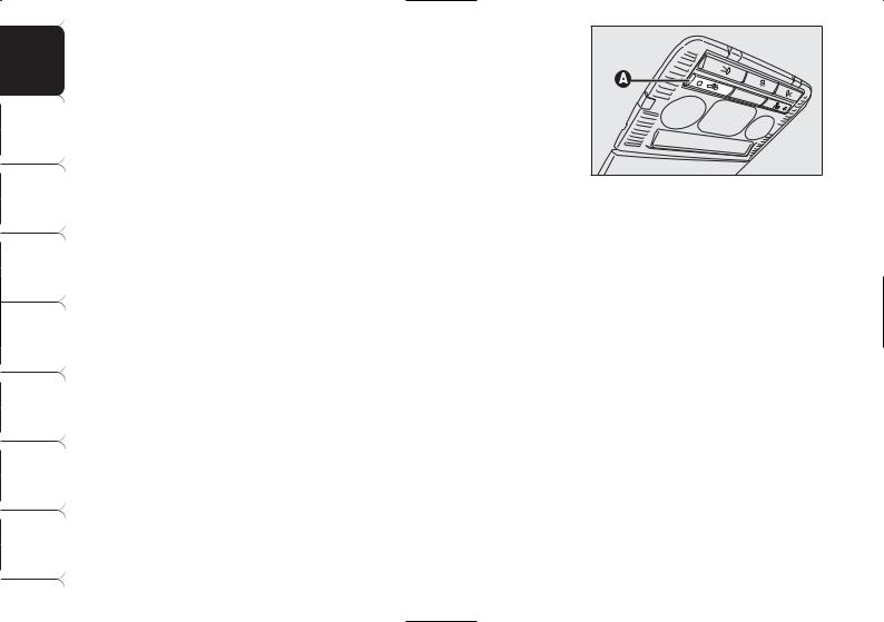
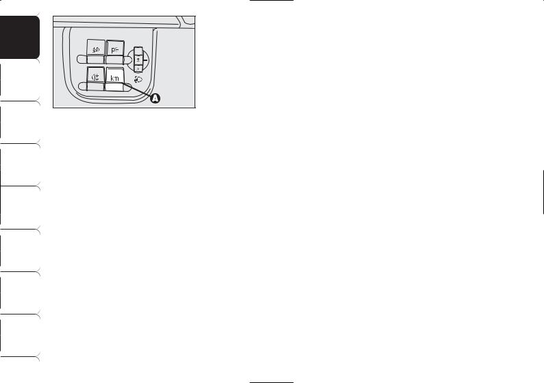
VOLUMETRIC PROTECTION/ ANTI-RAISING SENSORS
To make sure that the protection sensors are working properly, check that windows and sunroof (where provided) are shut.
This function can be cut out (for example if you leave animals on the car) by pressing button A-fig. 13 on the front ceiling light within 1 minute after instrument panel turning off.
When this function is off the button led will turn on. Volumetric protection/antiraising sensors cut out shall be repeated at each instrument panel turning off.

HOW TO CUT OFF
THE ALARM SYSTEM
To deactivate the alarm system completely (for instance during prolonged inactivity of the car) simply lock the car by rotating the metal insert (provided inside the electronic key) into the driver’s door lock.
MINISTERIAL
HOMOLOGATION
In keeping with the laws in force in each country on the subject of radio frequency, for markets in which the transmitter needs to be marked the certification number is given on the component. For certain versions/markets, the code may also be marked on the transmitter and/or on the receiver.
IGNITION DEVICE
The ignition device is located on the dashboard and it consists of the following:
electronic key reading device A- fig. 14 (set near the steering wheel);
button START/STOP (set under the electronic key reading device).
IMPORTANT To prevent running down the battery do not leave the electronic key into the ignition device when the engine is off.
WARNING
If the ignition device is tampered with (for example during an attempted
break-in) have it checked over by Alfa Romeo Authorized Services before travelling again.
fig. 14 |
A0E0219m |
|
WARNING
When leaving the car always remove the electronic key from the ignition device to prevent any passenger in the car from inadvertently activating the controls. Remember to engage the handbrake and if the car is facing uphill, first gear and if the car is facing downhill, reverse. Never leave children unat-
tended in the car.
DASHBOARD |
AND CONTROLS |
SAFETY |
DEVICES |
CORRECT USE |
OF THE CAR |
WARNING LIGHTS |
AND MESSAGES |
IN AN |
EMERGENCY |
CAR |
MAINTENANCE |
TECHNICAL |
SPECIFICATIONS |
INDEX |
|
19
DASHBOARD AND |
CONTROLS |
SAFETY |
DEVICES |
CORRECT USE |
OF THE CAR |
WARNING LIGHTS |
AND MESSAGES |
IN AN |
EMERGENCY |
CAR |
MAINTENANCE |
TECHNICAL |
SPECIFICATIONS |
|
INDEX |
20
fig. 15 |
A0E0028m |
|
ENGINE STARTING
See paragraph “Engine starting” in section “Correct use of the car”.
START/STOP BUTTON fig. 15
Button START/STOP, set on the dashboard, controls car electric systems and engine starting/stopping.
Button START/STOP is fitted with knurled ring and led. When the led and the instrument panel are on, the engine can be started.
TURNING THE INSTRUMENT PANEL ON
Proceed as follows:
fit the electronic key into the ignition device;
if the electronic key is fitted yet, press button START/STOP without pressing the clutch or brake pedal.
To safeguard the battery, when leaving the car with the instrument panel on, electric and electronic devices will be deactivated after approx. 1 hour.
IMPORTANT Fit completely the electronic key into the ignition device until it locks into place.
IMPORTANT Contact Alfa Romeo Authorized Services if the instrument panel fails to turn on.
IMPORTANT If when fitting the electronic key into the ignition device, the warning light Yon the instrument panel comes on (on certain versions together with a message on the display), check whether the electronic key is the proper one and then try to refit it into the ignition device. If the problem persists contact Alfa Romeo Authorized Services.
TURNING THE INSTRUMENT PANEL OFF
With engine off and clutch and brake pedals released, press button START/ STOP or remove the electronic key from the ignition device.
A few seconds after the instrument panel display will turn off gradually.
IMPORTANT Contact Alfa Romeo Authorized Services if the instrument panel fails to turn off.
STEERING COLUMN LOCK
Engaging
The steering column lock will engage 5 seconds after removing the electronic key from the ignition device and if the following conditions are present:
engine off;
instrument panel off with car at a standstill;
electronic key removed from ignition device.
Disengaging
The steering column lock will disengage after fitting the electronic key into the ignition device.
IMPORTANT Switching the engine off when the car is running will not engage the steering column lock till next switching off with car stopped. In this event warning light >(where provided) on the instrument panel will come on (or as an alternative, on certain versions, a symbol and a message are displayed).
IMPORTANT Steering column lock failure is indicated by the instrument panel warning light > (where provid-
ed) (or as an alternative, on certain versions, a symbol and a message are displayed). In this event contact Alfa Romeo Authorized Services.
IMPORTANT If after trying to turn on the instrument panel and/or to start the engine, the instrument panel warning light > (where provided) (or as an alternative, on certain versions the message "Vehicle protection system not available" is displayed), repeat the operation moving the steering wheel in order to release the steering lock. The displayed warning message will not impair steering lock operation.
WARNING
It is absolutely forbidden to carry out whatever after-market operation
involving steering system or steering column modifications (e.g.: installation of anti-theft device) that could badly affect performance and safety, cause the lapse of warranty and also result in non-compliance of the car with homologation requirements.
INSTRUMENTS
REV. COUNTER
Rev counter shows engine rpm. The red zone at the scale bottom indicates that the engine is running at excessive rpm dangerous for mechanical components. Do not drive with the pointer in this area.
IMPORTANT The electronic injection control system gradually shuts off the flow of fuel when the engine is “overrevving” (rev counter pointer in the red area) resulting in a gradual loss of engine power, in order to bring engine rpm below to the safety limit.
The rev counter may, when the engine is idling, indicate gradual or sudden increase of engine revs as the case may be; such behaviour is normal and must not be interpreted as a faulty condition as it occurs during normal operation, for instance when climate control or electric fan are switched on. In particular, slow revs variation helps keep the battery charged.
DASHBOARD |
AND CONTROLS |
SAFETY |
DEVICES |
CORRECT USE |
OF THE CAR |
WARNING LIGHTS |
AND MESSAGES |
IN AN |
EMERGENCY |
CAR |
MAINTENANCE |
TECHNICAL |
SPECIFICATIONS |
INDEX |
|
21
DASHBOARD AND |
CONTROLS |
SAFETY |
DEVICES |
CORRECT USE |
OF THE CAR |
WARNING LIGHTS |
AND MESSAGES |
IN AN |
EMERGENCY |
CAR |
MAINTENANCE |
TECHNICAL |
SPECIFICATIONS |
|
INDEX |
22
fig. 17 |
A0E00177m |
|
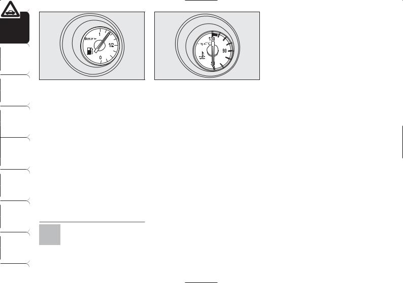
FUEL GAUGE fig. 17
This shows the amount of fuel left in the fuel tank.
0 - tank empty.
1 - tank full (see the indications given in paragraph “At the filling station").
The warning light on the fuel level gauge turns on when about 10 litres fuel are left in the tank. On certain versions. the display will show a warning message when the cruising range is less than 50 km (or 31 mi).
If warning light K starts flashing when travelling contact immediately Alfa Romeo Authorized Services.
fig. 18 |
A0E0178m |
|
IMPORTANT The pointer can reach the red area also for a sum of unfavourable conditions, i.e.: slow speed, uphill, fully laden or towing a trailer with hot outside temperature.
IMPORTANT Refuelling shall always be performed with engine off. Failing to observe this precaution could cause the gauge to provide wrong indications. Should this occur, to restore proper indication just have next refuelling with the engine off. Otherwise contact Alfa Romeo Authorized Services.
ENGINE COOLANT TEMPERATURE GAUGE fig. 18
This shows the temperature of the engine coolant fluid and begins working when the fluid temperature exceeds approx. 50°C.
The pointer should normally be towards the middle of the scale. If the pointer reaches the red sector, reduce your demand on the engine.
The turning on of the warning light u (on certain versions together with a message on the display) indicates that the coolant fluid temperature is too high; in this case, stop the engine and contact Alfa Romeo Authorized Services .
IMPORTANT The pointer can reach the red area also for a sum of unfavourable conditions, i.e.: slow speed, uphill, fully laden or towing a trailer with hot outside temperature.
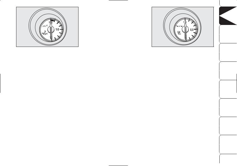
fig. 19 |
A0E0179m |
|
ENGINE OIL TEMPERATURE GAUGE (petrol versions) fig. 19
This shows the temperature of the engine oil and begins working when the oil temperature exceeds approx. 70°C.
If the pointer reaches the red sector, reduce your demand on the engine.
The turning on of the warning light ` when travelling (on certain versions together with a message on the display) indicates that the oil temperature is too high; in this case, stop the engine and contact Alfa Romeo Authorized Services.
IMPORTANT The pointer can reach the red area also for a sum of unfavourable conditions, i.e.: slow speed, uphill, fully laden or towing a trailer with hot outside temperature.
fig. 20 |
A0E0180m |
|
TURBOCHARGER PRESSURE GAUGE (diesel versions) fig. 20
This shows the turbocharger pressure value.
DASHBOARD |
AND CONTROLS |
SAFETY |
DEVICES |
CORRECT USE |
OF THE CAR |
WARNING LIGHTS |
AND MESSAGES |
IN AN |
EMERGENCY |
CAR |
MAINTENANCE |
TECHNICAL |
SPECIFICATIONS |
INDEX |
|
23
DASHBOARD AND |
CONTROLS |
|
|
SAFETY |
DEVICES |
|
|
CORRECT USE |
OF THE CAR |
fig. 21 |
A0E0072m |
|
|||
TRIP METER RESET fig. 21 |
|||
WARNINGLIGHTS |
MESSAGESAND |
To reset the trip meter, keep button A |
|
pressed for a few seconds. |
|||
|
|
||
IN AN |
EMERGENCY |
|
|
CAR |
MAINTENANCE |
|
|
TECHNICAL |
SPECIFICATIONS |
|
|
|
INDEX |
|
24
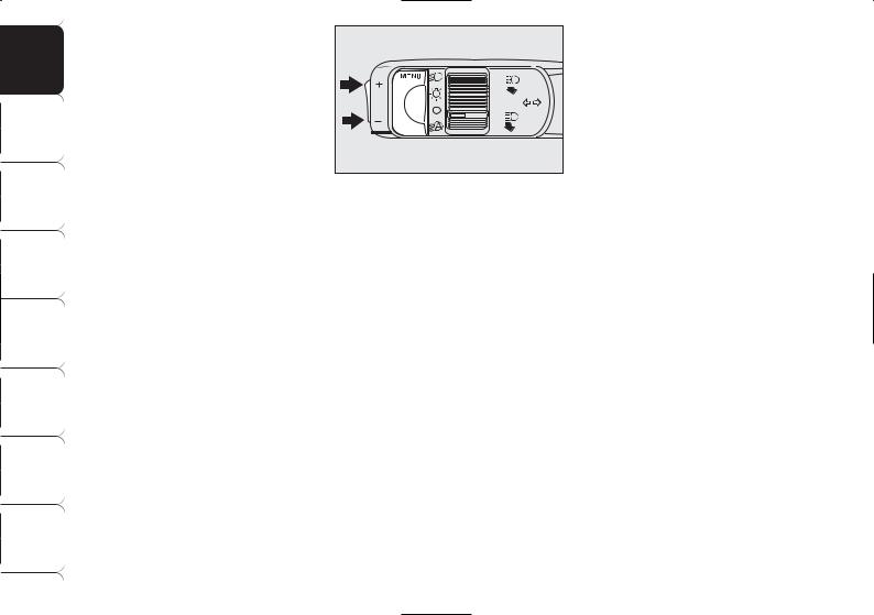
MANUAL INSTRUMENT PANEL LIGHT DIMMER
With this function it is possible to adjust on 8 levels the light intensity of the indications given on the instrument panel display, sound system display (where provided), climate control system display, radionavigation system display (where provided), and instrument panel gauges (fuel level gauge, engine oil temperature gauge (petrol versions) or supercharger pressure gauge (diesel versions) and engine coolant temperature gauge).
To increase light intensity press briefly button + on the left-hand stalk, to reduce it press button –: the display will show an indication and a figure corresponding to the current light intensity level. This screen will be displayed for a few seconds and then it will go off.
AUTOMATIC INSTRUMENT PANEL LIGHT DIMMER
To give max. visibility and comfort under whatever driving conditions (e.g.: lights on in daylight, tunnels, etc…), the speedometer is fitted with a sensor for adjusting automatically, after fitting the electronic key into the ignition device and pressing button START/ STOP, the light intensity of the indications given on the instrument panel display, sound system display (where provided), climate control system display, radionavigation system display (where provided), and instrument panel gauges (fuel level gauge, engine oil temperature gauge (petrol versions) or supercharger pressure gauge (diesel versions) and engine coolant temperature gauge).

MULTIFUNCTION
DISPLAY
(where provided)
The “Multifunction display” shows all the useful information necessary when driving, more particularly:
INFORMATION ON
STANDARD SCREEN
Clock A-fig. 22;
External temperature B;
Total km (or mi) or trip meter C (when total kilometres (or miles) are indicated the display will also show the wording TOT).
Fitting the electronic key into the ignition device will display the total km (or mi), press button A-fig. 23 for trip meter (or mi).
fig. 22 |
A0E0060m |
|
fig. 23 |
A0E0072m |
|
To reset the trip meter (or mi), press for long button A-fig. 23 during displaying.
INFORMATION ABOUT CAR CONDITIONS (at event)
Scheduled servicing (symbol õ
D-fig. 22).
Instrument panel light dimmer.
Symbol of possible presence of ice on the road (symbol √ E-fig. 22).
Speed limit exceeded.
Engine oil level.
DASHBOARD |
AND CONTROLS |
SAFETY |
DEVICES |
CORRECT USE |
OF THE CAR |
WARNING LIGHTS |
AND MESSAGES |
IN AN |
EMERGENCY |
CAR |
MAINTENANCE |
TECHNICAL |
SPECIFICATIONS |
INDEX |
|
25
DASHBOARD AND |
CONTROLS |
SAFETY |
DEVICES |
CORRECT USE |
OF THE CAR |
WARNING LIGHTS |
AND MESSAGES |
IN AN |
EMERGENCY |
CAR |
MAINTENANCE |
TECHNICAL |
SPECIFICATIONS |
|
INDEX |
26
“SETUP MENU”
There is also a “Setup Menu” enabling to perform the adjustments and/or settings described on the following pages by pressing button MENU and +/– (see fig. 24). The Setup can be activated by pressing briefly button MENU.
With the car stopped, the following settings are enabled:
Speed limit on/off and speed limit value.
Clock.
Failure/warning buzzer volume.
“Distance” unit.
With the car running, only the following setting is enabled:
Speed limit on/off and speed limit value setting.
fig. 24 |
A0E0074m |
|
CONTROL BUTTONS
(set on left stalk) fig. 24
MENU
Short push on button: to confirm the required option and/or to go to next screen;
Long push on button: to confirm the required option and to go back to standard screen;
+/– to scroll up/down the “Setup Menu” options or to increase/decrease the value displayed on the screen.
When the standard screen is displayed buttons +/– activate instrument panel light dimming.
Speed limit (SPEED BEEP)
With this function it is possible to set the car speed limit (km/h or mph) which, if exceeded, automatically sounds a buzzer and displays a specific message (see section “Warning lights and messages”) to alert the driver. Once the warning cycle is over the display will resume the standard screen. The warning message will disappear only after the car speed slows 5 km/h (5 mph) below the set speed limit or after pressing briefly the MENU button. This procedure is carried out just once after exceeding the speed limit and it can be repeated only if the car speed slows at least 5 km/h (5 mph) below the set speed limit and then it increases until exceeding the speed limit again.

To set the speed limit, proceed as follows:
press button MENU until selecting SPEED BEEP: the display will show SPEED BEEP and setting condition (ON = speed limit on/ OFF= speed limit off);
press again button MENU: ON (or OFF) will flash;
press buttons +/– to select ON or
OFF;
selecting ON will make the last speed limit set flashing on the display;
press buttons +/– to adjust the value.
IMPORTANT The possible setting is between 30 and 250 km/h (or between 20 and 150 mph) depending on the unit set previously (see paragraph “Units” described later). Every press (pulse) of the button +/– increases or decreases the value by 5 units. Keeping the button +/– pressed obtains automatic fast increase or decrease. When you are near the required setting complete adjustment with single presses.
Clock (TIME REG)
This function enables to adjust the clock.
To adjust the clock proceed as follows:
press button MENU until selecting
TIME REG;
press again button MENU: TIME and clock will flash;
press buttons +/– to adjust time.
Clock is always displayed in 24h mode (24 hours).
Failure/warning buzzer volume (BUZZ)
With this function the volume of the buzzer accompanying any failure/warning indications can be adjusted according to 4 levels. The buzzer can be adjusted and excluded.
Proceed as follows:
press button MENU until selecting BUZZ: the display will show BUZZ and a figure corresponding to the buzzer volume level;
press again button MENU: the figure will flash;
press buttons +/– to adjust the buzzer volume.
To mute the buzzer set the volume level to “0” using buttons +/–.
DASHBOARD |
AND CONTROLS |
SAFETY |
DEVICES |
CORRECT USE |
OF THE CAR |
WARNING LIGHTS |
AND MESSAGES |
IN AN |
EMERGENCY |
CAR |
MAINTENANCE |
TECHNICAL |
SPECIFICATIONS |
INDEX |
|
27

DASHBOARD AND |
CONTROLS |
SAFETY |
DEVICES |
CORRECT USE |
OF THE CAR |
WARNING LIGHTS |
AND MESSAGES |
IN AN |
EMERGENCY |
CAR |
MAINTENANCE |
TECHNICAL |
SPECIFICATIONS |
|
INDEX |
Distance unit (UNIT)
With this function it is possible to set the required distance unit (km or mi).
To set the distance unit, proceed as follows:
press button MENU until selecting UNIT: the display will show UNIT and “km” or “mi”;
press again button MENU: “km” (or “mi”) will flash;
press buttons +/– to set the required distance unit.
Scheduled servicing
IMPORTANT The Service schedule includes car maintenance every 35,000 km (or 21,000 mi); this is shown automatically, with the electronic key into the ignition device starting from 2,000 km (or 1,240 mi) from this deadline and it will be displayed in km or miles according to the unit set. When a scheduled service interval (“coupon”) is near to come, fitting the electronic key into the ignition device will display a message followed by the number of km/mi to go before car servicing. Contact Alfa Romeo Authorized Services to carry out any service operation provided by the Service schedule or by the Annual inspection plan, and to reset the display.
ENGINE OIL LEVEL
INDICATION
Fitting the electronic key into the ignition device, the display will show for a few seconds the engine oil level. At this stage, to clear this indication and to go to next screen, press button MENU.
Low oil level will be indicated by a dedicated warning message on the display.
IMPORTANT Check the proper engine oil level on the dipstick (see paragraph “Checking levels” in section “Car maintenance”).
IMPORTANT Proper engine oil level shall be checked with the car on level ground.
IMPORTANT To read the correct oil level after fitting the electronic key, wait for about 2 seconds before starting the engine.
IMPORTANT Engine oil level could increase after a long stop.
28

MESSAGES DISPLAYED AT STARTING
After the engine oil level, the display will show for a few seconds a message indicating the procedure to follow to start the engine (PRESS PEDAL AND START: press brake or clutch pedal and then press button START/STOP to start the engine).
ILLUMINATION OF REV COUNTER/INSTRUMENTS (NIGHT PAN)
This function enables to turn on/off (ON/OFF) the lights of the rev counter and instruments.
This function can be activated (only with electronic key fitted into ignition device, external lights on, and speedometer built-in sensor in poor outside light setting), by pressing for long button –. When this function is on, the display will show “NIGHT PAN ON”.
Once on, the NIGHT PAN function can be deactivated as follows:
by long press on button + (also with external lights off);
removing the electronic key from the ignition device.
When this function is off the display shows “NIGHT PAN OFF”.
Messages “NIGHT PAN ON” or “NIGHT PAN OFF” stay on the display for a few seconds, then they will go off. To stop displaying before time, briefly press button MENU.
DASHBOARD |
AND CONTROLS |
SAFETY |
DEVICES |
CORRECT USE |
OF THE CAR |
WARNING LIGHTS |
AND MESSAGES |
IN AN |
EMERGENCY |
CAR |
MAINTENANCE |
TECHNICAL |
SPECIFICATIONS |
INDEX |
|
29
 Loading...