

Page 1

REFERENCE MANUAL
Page 2

Page 3

TABLE OF CONTENTS
INTRODUCTION .................................................................................................................................. 2
FIRST THINGS FIRST: DRIVER INSTALLATION......................................................................... 3
WINDOWS ........................................................................................................................................ 3
MAC OS X......................................................................................................................................... 3
INSTALLING THE OPTIONAL APPLICATIONS............................................................................. 3
REAR PANEL FEATURES.................................................................................................................. 4
TOP PANEL FEATURES ....................................................................................................................6
(A) ANALOG INPUT SIGNAL INDICATORS .................................................................................... 6
(B) DAW CONTROL: CHANNELS................................................................................................... 7
(C) DAW CONTROL: MULTI-FUNCTION KNOBS .......................................................................... 8
(D) DAW CONTROL: TRANSPORT ................................................................................................8
(E) DAW CONTROL: ASSIGNABLE BUTTON BANKS .................................................................. 9
(F) MONITORING / CONTROL ROOM FEATURES ......................................................................... 9
(G) CONFIGURATION CONTROLS................................................................................................ 10
CONFIGURING YOUR DIGITAL AUDIO WORKSTATION SOFTWARE FOR USE WITH
THE MASTERCONTROL.................................................................................................................. 12
SELECTING THE PROPER PRESET FOR YOUR DAW................................................................ 12
CUBASE AND NUENDO SETUP: SELECTING THE AUDIO DRIVER (WINDOWS ONLY)......... 13
CUBASE AND NUENDO SETUP: CONTROL SURFACE (MAC AND WINDOWS)...................... 14
ABLETON LIVE SETUP.................................................................................................................. 17
CAKEWALK SONAR SETUP ......................................................................................................... 22
LOGIC PRO SETUP........................................................................................................................ 26
SAMPLITUDE SETUP..................................................................................................................... 28
DIGITAL PERFORMER SETUP...................................................................................................... 28
PRO TOOLS SETUP....................................................................................................................... 28
REASON SETUP ............................................................................................................................ 28
SOUNDTRACK PRO SETUP.......................................................................................................... 28
AUDIO INPUTS AND OUTPUTS ..................................................................................................... 29
WINDOWS AUDIO CONFIGURATION............................................................................................ 30
CHOOSING THE MASTERCONTROL AS YOUR DEFAULT AUDIO DEVICE............................... 30
DISABLING WINDOWS SYSTEM SOUNDS ..................................................................................31
ALESIS FIREWIRE CONTROL PANEL (WINDOWS)..................................................................... 32
MAC AUDIO CONFIGURATION...................................................................................................... 34
AUDIO MIDI SETUP........................................................................................................................ 34
ALESIS FIREWIRE CONTROL PANEL (MAC) .............................................................................. 35
GLOBAL MENUS ............................................................................................................................... 36
MONITORING & CONTROL ROOM FEATURES.......................................................................... 39
DIRECT MONITORING ..................................................................................................................... 40
CREATING A CUBASE LE PROJECT FOR RECORDING ......................................................... 41
IMPORTANT POINTS FOR USERS OF VARIOUS DAWS .......................................................... 44
CUBASE / NUENDO ....................................................................................................................... 44
ABLETON LIVE .............................................................................................................................. 44
CAKEWALK SONAR...................................................................................................................... 44
LOGIC PRO .................................................................................................................................... 45
SAMPLITUDE ................................................................................................................................. 45
DIGITAL PERFORMER................................................................................................................... 46
ALESIS HD24 / HD24XR................................................................................................................. 46
PRO TOOLS ................................................................................................................................... 47
REASON ......................................................................................................................................... 47
SOUNDTRACK PRO ...................................................................................................................... 47
PLUG-IN 1, 2................................................................................................................................... 48
SIGNAL FLOW DIAGRAM ................................................................................................................ 49
SPECIFICATIONS.............................................................................................................................. 50
TRADEMARKS ................................................................................................................................... 51
CONTACT INFORMATION............................................................................................................... 51
DEMO MATERIALS........................................................................................................................... 51
Page 4

INTRODUCTION
Congratulations on your purchase of the Alesis MasterControl!
The MasterControl is Alesis’s most advanced computer recording product to date and designed to be
the centerpiece of your studio. Just consider this list of features:
y 24-bit, 192kHz audio interface with analog preamplifiers and line inputs, plus ADAT and S/PDIF
digital audio inputs. Up to twenty-six inputs and six outputs can be used simultaneously.
Standard MIDI inputs and outputs are included, too.
y Audiophile performance from 111dB ADCs, 114db DACs, and a high-definition microphone
preamplifier design. All line inputs and outputs are balanced for maximum signal-to-noise
(SNR) performance.
y Full featured control surface with 100mm motorized faders, three-row knob control, assignable
buttons, transport control, preview functionality, and a dedicated display to keep you oriented at
all times.
y Templates for all the most popular DAWs are included. Call up a preset and use the included
templates to make the most out of your preferred music creation software.
y Sophisticated control room functionality including freely assignable outputs, dedicated buttons
for speaker switching, two independent headphone outputs, and integrated talkback
microphone.
y DSP-driven, 26x6 built-in hardware mixer for tracking live instruments and vocals with no
discernible latency.
y Low-latency ASIO, WDM, and CoreAudio drivers for high performance and the lowest possible
latency.
y Steinberg Cubase and Ableton Live Lite Alesis Edition included in the box so you can get
started recording and mixing immediately.
How this manual is organized
This reference manual is designed to get you up and running with the MasterControl fast. After
providing an overview of the MasterControl’s physical features, the manual guides you through driver
installation and then connecting your MasterControl to your DAW software.
Once you have connected your MasterControl, you are ready to move on to the next step: customizing
the MasterControl for your own mode of working. This customization occurs within the GLOBAL menus.
Next, you will learn about the powerful features of the built-in DIRECT MONITORING mixer.
At the end of this manual, there is a quick tutorial for starting a Cubase LE project, followed by a list of
unique features pertinent to the various presets.
Enjoy your Alesis MasterControl—the new centerpiece of your recording studio!
2
Page 5

pp
D
FIRST THINGS FIRST: DRIVER INSTALLATION
IMPORTANT!!! Follow these steps BEFORE you plug in your MasterControl for the first time.
If your computer has Internet access, go to http://www.alesis.com/mastercontrol
updated drivers have been posted there since the time the software DVD included with your
MasterControl was printed.
. It’s possible that
WINDOWS
If you are using the drivers from the DVD, click to begin the
MasterControl driver installer from the DVD’s splash screen.
If you downloaded the drivers from http://www.alesis.com, open them
from the location where you saved them.
Depending upon your computer’s configuration, you will be guided
through as few as one and as many as four separate (though
similar-looking) driver installations: one for “Alesis MasterControl,”
one for “Alesis Firewire Audio,” and two for “Alesis Firewire MIDI.”
For each of the installations that occur, you
may see the window shown here warning you
that the drivers have not passed Microsoft
Logo Certification. Click “Continue Anyway,”
and follow the on-screen instructions.
Be sure to complete every stage of the
installation. Do not cancel any of the
installations, as they are all required for proper
operation. When all the drivers are installed,
you will see a message at the bottom right of
your screen stating, “Your new hardware is
installed and ready to use.”
These drivers include the two
most popular standards for
audio interfacing – WDM (the
“Windows Driver Model” built
by Microsoft) and ASIO (the
“Audio Stream Input/Output”
standard used by many audio
software a
lications).
MAC OS X
Driver installation in Mac OS X is more straightforward, as only
CoreAudio and CoreMIDI drivers are installed. From the DVD,
nagivate to the appropriate folder for MasterControl drivers. Click
the installer program to install the drivers.
Note: Mac OS X 10.4 or
higher is required by the
MasterControl.
INSTALLING THE OPTIONAL APPLICATIONS
The software DVD that comes with the MasterControl contains some powerful music applications.
If you don’t already have a Digital Audio Workstation (DAW) program,
install Cubase LE and or Ableton Live Lite Alesis Edition, both of which
are provided on the DVD. These programs are a fantastic way to get
started in computer-based recording. You may find that they are the
only programs you need.
ue to their limited track
counts, these programs
cannot access all of the
MasterControl’s twenty-six
inputs at the same time.
3
Page 6

y
REAR PANEL FEATURES
1 1
3 3
2 2
4
5
5 5 5
5
5 5 5
5
6 6 6
5
6 6 677 8
9 9
10 10 10 11 11 12
13
1. MIC / LINE INPUTS – These two inputs can accept microphones (using an XLR cable) or an
instrument or line-level device (using a 1/4” cable) such as a guitar, bass, sampler, or other audio
device. These are balanced, low-impedance inputs. For best results when connecting balanced,
line-level gear, use a TRS (tip-ring-sleeve) cable to connect to the 1/4" inputs.
2. GAIN KNOBS – The two MIC / LINE INPUTS each have a small dedicated GAIN knob for gain
trim adjustment. By sweeping the GAIN knob, the XLR input provides from +9dB to +59dB of gain,
perfect for a wide range of microphones. The 1/4" TRS input provides from -7dB to +43dB of gain,
allowing you to attenuate overly “hot” signals from line-level equipment.
3. INSERTS – These two inputs can be used to connect a compressor, equalizer, noise gate, or
other external processor to the corresponding channel. A channel insert affects the channel’s
audio before it is sent to your DAW. Use a dedicated insert cable to connect external gear to the
insert jacks.
4. PHANTOM POWER – For phantom-powered mics,
depress this button labeled “48 VOLT.” Note that this
button applies phantom power to the XLR portion of the
combo jacks (not the 1/4" portion of those jacks) for both
To minimize noise, only engage the
MasterControl’s phantom power if
ou are using a mic that requires it.
inputs 1 and 2.
5. LINE INPUTS – Use 1/4” cables to connect your instruments or line-level devices to these six,
fixed-gain inputs. Like the MIC / LINE INPUTS, these inputs are balanced (TRS). They can be
used with both unbalanced and balanced input equipment.
6. MONITOR / LINE OUTPUTS – Connect your monitors and/or external processing gear to these
outputs using 1/4” cables. These six outputs function in stereo pairs as follows (and are labeled as
such on the rear panel):
y “A” outputs (Channels 1 and 2)
y “B” outputs (Channels 3 and 4)
y “C” outputs (Channels 5 and 6)
Each of these channel pairs can be enabled individually or in any simultaneous combination via
the three SPEAKERS / MONITORS buttons on the top panel. In the GLOBAL MENUS (discussed
later), you can freely assign each of these outputs to any of the three stereo-pair outputs that come
out of your computer Digital Audio Workstation (DAW) software.
7. HEADPHONES – You can connect two sets of stereo headphones to these outputs. Like the “A” /
“B” / “C” outputs, you can choose any of the MasterControl’s three stereo output pairs for each
headphone output. The headphone volume levels are controlled by the HEADPHONE 1 and 2
knobs on the top panel.
4
Page 7

p
g
8. FOOTSWITCH – You may connect a remote footswitch to this jack. This can operate either
control option surface or
off. Please refer to the GLOBAL MENUS section to configure your footswitch.
9. MIDI IN / OUT – You can use MIDI cables to connect
an external MIDI device to these jacks.
10. DIGITAL INPUTS – This area features an ADAT
connection, a configurable ADAT/optical S/PDIF
connection, and a coaxial (RCA) S/PDIF connection.
The number of channels available via the digital input jacks changes as you change sampling
rates. Refer to the INPUTS / OUTPUTS & SAMPLING RATES section for more information.
11. FIREWIRE – Connect the MasterControl to your computer using either of these FireWire
connections. The second jack can be used to daisy chain another firewire device, such as an
external hard drive. If computer operation becomes glitchy, remove any other devices connected
to your FireWire chain to see if that solves the problem.
12. POWER IN – Connect the included power adapter to the MasterControl here. Only use an
approved Alesis adapter. Other adapters may damage your MasterControl.
as a toggle switch to turn the MasterControl’s talkback function on and
Note: These MIDI connections may
be disabled when recording at
176.4kHz and 192kHz sam
The digital section is INPUT only.
The MasterControl does not have
di
ital audio outputs.
as a
le rates.
5
Page 8

TOP PANEL FEATURES
This section breaks down the control surface into its functional areas. The area being discussed is
shaded in the accompanying diagrams.
A
C
F
B
(A) Analog Input Signal Indicators
(B) DAW Control: Channels
(C) DAW Control: Multi-Function Knobs
(D) DAW Control: Transport
(E) DAW Control: Assignable Button Banks
(F) Monitoring / Control Room Features
(G) Configuration Controls
(A) ANALOG INPUT SIGNAL INDICATORS
G
F
E
F
D
F
1
1. SIGNAL / CLIP – There is one LED for each analog input channel. This LED turns green when
signal is detected and turns red when the signal nears 0dBFS (zero decibels full-scale, the point
where nasty digital distortion occurs). Avoid digital distortion either by reducing the trim on the first
two inputs or by reducing the volume level on any equipment connected to the analog inputs.
6
Page 9

(B) DAW CONTROL: CHANNELS
4
3
3
3
3
5
6
1 2
1. CHANNEL FADER – Use this 100mm, touch-sensitive fader to adjust the volume levels of each
channel. The exact level will be shown in the DISPLAY.
2. MASTER FADER – This fader controls the DAW’s master fader. Note that different DAWs control
this fader differently. Some DAWs, such as Pro Tools, do not make use of the fader at all.
3. SELECT / RECORD / SOLO / MUTE – These buttons control the corresponding functions in your
DAW.
4. PREVIEW – Using this button to keep from becoming “lost” on the control surface. Press and hold
PREVIEW and manipulate a control to see its operation and, if applicable, the DAW project’s
corresponding track name on the LCD display. As long as PREVIEW is held down,
communication with the DAW will be suspended for most controls.
5. < BANK > – Use these buttons to move through your DAW project’s channels in banks of eight.
The first and last fader assignments for the selected bank will be shown in the DISPLAY.
6. < TRACK > – Use these buttons to move through your DAW project’s channels one at a time.
7
Page 10

(C) DAW CONTROL: MULTI-FUNCTION KNOBS
1
2
1. TEMPLATE OVERLAY – Place the long plasticized overlay (included) that matches your currently
selected DAW preset here.
Remove the plastic protective covering from the template overlay before placing it in the slot.
Insert one end first, then bend the overlay slightly upwards in order to slide the overlay into the
opposite slot.
2. ROW SELECT – Use the ROW SELECT buttons to select which row of parameters the CHANNEL
KNOBS are currently controlling. An LED next to the selected row indicates the currently selected
row.
3. 360° KNOB – Turning this 360° knob adjusts the parameter indicated for the currently selected
row.
3
(D) DAW CONTROL: TRANSPORT
1. REW / FF/ STOP / PLAY / REC – These buttons
control your DAW’s transport operations.
2. JOG WHEEL – Use this to scroll the backwards or
forwards in your DAW. This has the same effect as
the REW / FF buttons.
3. UP / DOWN / LEFT / RIGHT – These buttons serve
different functions depending on whether the
MasterControl’s Zoom or Scrub functions are
enabled.
4. ZOOM – When you engage this button, you can use
the UP / DOWN / LEFT / RIGHT buttons to zoom in
or out of the selected track in the DAW. Use the
LEFT / RIGHT buttons to zoom horizontally or the
UP / DOWN buttons to zoom vertically, depending
on what your DAW allows.
5. SCRUB – When you engage this button, you can “scrub” through the audio in the DAW, playing it
backwards or forwards at a pitch/speed determined by how fast the play head is moving. To
scrub, you can use the LEFT / RIGHT buttons, the REW / FF buttons, or the JOGWHEEL.
Note that ZOOM and SCRUB operate differently in different software programs. These features
are not supported by all programs. For instance, SCRUB is not available in Cubase LE4.
4 5
3
2
3
1
33
8
Page 11

(E) DAW CONTROL: ASSIGNABLE BUTTON BANKS
1. TEMPLATE OVERLAY - Place the short
plasticized overlay (included) that matches your
currently selected DAW preset here.
2. ASSIGNABLE BUTTONS – These buttons
perform functions in your DAW such as SAVE,
LOOP, etc. For most presets, you can re-assign
the buttons to various functions by pressing EDIT
at the upper right of the MasterControl.
3. BUTTONS A / B – Press this button to toggle
between the two banks of ASSIGNABLE
BUTTONS. When this button is unlit, the
ASSIGNABLE BUTTONS are in Bank A. When
this button is lit, the ASSIGNABLE BUTTONS are in Bank B. This provides control over 8 x 2
functions.
1
2
2
3
(F) MONITORING / CONTROL ROOM FEATURES
7
2
3
1
555
6
1. DIRECT MONITOR - Press this button to put the MasterControl into DIRECT MONITOR mode. In
this mode, the channel strips on the control surface stop communicating with your DAW and,
instead, affect the volume and panning for your incoming audio signals. This hardware direct
monitoring allows you and your musicians to monitor your incoming audio with zero computerinduced latency.
Use the BANK and TRACK buttons to navigate between the various analog and digital inputs. For
more information on this important feature, see the DIRECT MONITOR section later in this
manual.
4
4
9
Page 12

2. DIRECT MON LEVEL – This knob raises or lowers your entire direct monitor mix. This allows you
to blend your direct monitor signals with the audio being played from your computer.
3. OUTPUT 1-2 LEVEL – This knob controls the volume sent out of the analog outputs for any of the
analog output pairs that are set to listen to DAW outputs 1/2.
4. HEADPHONE 1 / 2 – These knobs control the volume for the corresponding HEADPHONE 1 and
2 outputs on the rear panel. You can select which stereo channels are routed to these outputs in
the Global Menus (see the GLOBAL MENUS section for more information).
5. SPEAKERS / OUTPUTS – These buttons mute or activate output from each of the three physical
analog output pairs. To switch a stereo mix between multiple sets of speakers, set each of the
three output pair sources in the global menus to OUTPUT 1/2.
6. TALKBACK – Pressing this button will let you speak into the built-in microphone (right above the
button) to your musicians. This signal will interrupts any audio that would otherwise be playing.
Select which pairs of channels allow talkback, and set the talkback volume, in the Global Menus
(see the GLOBAL MENUS section for more information).
7. LED METERS – These meters measure the audio signal level of the Output Source 1/2 sent from
your computer software to the MasterControl.
(G) CONFIGURATION CONTROLS
1. DISPLAY – Information related to the
MasterControl’s functions will be shown in this
display. This includes functions currently being
adjusted, pages in menus, knob settings, volume
levels, the current bank or track, etc.
2. VALUE / ENTER – Turn this knob to scroll through
the various options shown in the DISPLAY. Push
the knob to enter your selection.
3. PRESET / HOME – Press this button to enter (or exit) Preset Selection. Use the VALUE / ENTER
encoder to scroll through the Presets to find the one corresponding to your DAW. Press the
encoder to select the preset. Do this before
you open your DAW. The Presets are as follows:
1
6
y Preset 1: Cubase / Nuendo
y Preset 2: Ableton Live
y Preset 3: Cakewalk Sonar
y Preset 4: Logic Pro
y Preset 5: Samplitude
y Preset 6: Digital Performer
y Preset 7: Alesis HD24
y Preset 8: ProTools
y Preset 9: Reason
y Preset 10: Soundtrack Pro
y Preset 11: Plug-in 1
y Preset 12: Plug-in 2
3
24
5
10
Page 13

4. EDIT – In Edit Mode, you can change the assignments for
the A and B banks of the ASSIGNABLE buttons – a total of
16 assignable functions. Upon entering Edit Mode, the
DISPLAY will look like the image on the right and the
ASSIGNABLE BUTTONS will light up orange. First, press the button whose function you want to
assign (the other buttons will become unlit). Then, use the VALUE / ENTER encoder to scroll
through the functions. Press VALUE / ENTER to select one. You may assign the same function to
multiple buttons.
Different functions are available for different DAWs. This depends on what the DAWs support.
For instance, an option to rapidly “flip” the faders and knobs, so that, for instance, you can perform
panning via the faders, is available for many but not all DAW presets.
5. GLOBAL – Press this to enter (or exit) the Global Mode where you can adjust the MasterControl’s
global configuration. Use the PAGE buttons to toggle through the available pages in the Global
Menus. Use VALUE / ENTER to scroll through the available options for any page; press it to save
your change for each menu. See the GLOBAL MENUS section for more information.
6. < PAGE > – Press either of these buttons to move to the previous (<) or next (>) page in the menu
in the DISPLAY.
TOUCH A CONTROL
(Enter to save)
11
Page 14

CONFIGURING YOUR DIGITAL AUDIO WORKSTATION
SOFTWARE FOR USE WITH THE MASTERCONTROL
Once your MasterControl is connected to your computer, there are three steps to perform to establish
audio and control surface communication with your Digital Audio Workstation (DAW):
1) On the MasterControl, select the proper MasterControl preset for your DAW.
2) In your DAW, select the MasterControl as your audio input/output device.
3) Still in your DAW, select the MasterControl as a control surface:
a. Add a “Mackie Control” device as an available control surface (the MasterControl uses
the “Mackie Control”/“MCU” protocol)
b. Choose the proper Alesis Firewire MIDI ports as the INPUT and OUTPUT ports for the
The following pages show you how to set up the Master Control to work with your DAW. The
instructions are provided for Windows users in most of the following examples.
Mac users should note that, in all cases, the Alesis drivers should be selected under AUDIO MIDI setup
before opening your DAW. In most cases for Mac, it will not be necessary for you to choose the Alesis
drivers within your DAW as well.
“Mackie Control” control surface.
SELECTING THE PROPER PRESET FOR YOUR DAW
To select the Preset to match your DAW, press PRESET/HOME on
the MasterControl. Turn the ENCODER to select the DAW program
that you are using. Finally, press the ENCODER to accept the
selection. Do all this before
Important: Be sure to select the proper preset for you DAW! If you
use the wrong MasterControl preset with a DAW program, the
communication between your computer and the MasterControl will not work correctly.
Your Preset selection will be saved even after you turn your MasterControl off. Therefore, you will only
need to change your preset when you switch to using a different DAW.
opening the DAW itself.
∗
;
The MasterControl uses the
industry-standard “Mackie
Control” protocol with most
DAWs. With Pro Tools, it uses
the “HUI” protocol.
∗
For Pro Tools, the “HUI” protocol is used, not the “Mackie Control” protocol. Otherwise, the process is
the same.
For all DAWs except ProTools, be sure to select “Mackie Control” or its equivalent, “MCU” as the control
surface — not “HUI.”
12
Page 15

CUBASE AND NUENDO SETUP: SELECTING THE AUDIO DRIVER
(WINDOWS ONLY)
This discussion addresses Cubase. Nuendo setup is similar.
1. From the menu bar, go to Devices f Device Setup…
2. Click on “VST Audio System” in the left-hand pane. Then, in the right-hand pane, select “ASIO
Alesis Firewire” for the ASIO driver.
13
Page 16

CUBASE AND NUENDO SETUP: CONTROL SURFACE (MAC AND
WINDOWS)
1. Again from the menu bar, go to Devices f Device Setup…
2. Click the “+” button on the upper-left corner of the window and select “Mackie Control” from the list.
14
Page 17

3. Under Remote Devices f Mackie Control, select “Alesis FireWire” from the MIDI Input and MIDI
Output drop-down menus.
4. Press “OK” to accept this setting.
5. Once the MasterControl is selected as the audio device,
individual channels must be activated for use. From the
“Devices” menu, select “VST Connections.”
Some versions of Cubase,
including Cubase LE provided
with the MasterControl, do not
allow all inputs to be used
simultaneously.
15
Page 18

6. In this first tab labeled “Inputs,” you can decide which of the MasterControl’s channels will be
routed to the Cubase’s inputs. Click the entries under “Device Port” to select an available channel
from a drop-down menu. (This number and kind of available channels will vary depending on the
sampling rate.) If necessary, you can add more buses by clicking the “Add Bus” button.
7. In the “Outputs” tab, you can decide which of the Cubase channels will be routed to the
MasterControl’s outputs. Click the entries under “Device Port” to select an available channel from
a drop-down menu. Note that the only available options are the six physical outputs (the MON /
LINE OUTPUTS on the rear panel of the MasterControl).
16
Page 19

8. If you want, you can rename channels by clicking on the entry under “Bus Name.” This is useful
for keeping track of which instrument is on each stereo channel.
9. Close the window. You are now ready to begin recording with the MasterControl.
10. See the Cubase/Nuendo notes later in this manual for details on MasterControl operation with
these DAWs.
ABLETON LIVE SETUP
1. From the menu bar, go to Options f Preferences (Windows XP) or to Live f Preferences
(Mac).
17
Page 20

2. Click the MIDI/Sync tab. Select “MackieControl” from the Control Surface drop-down menu, and
select “Alesis FireWire” for the corresponding Input and Output.
3. Click the Audio tab. Select “ASIO” from the Driver Type drop-down menu. (The MasterControl will
still work if another option like MME/DirectX is selected, but we recommend using ASIO as it is a
better choice.) Then select “ASIO Alesis FireWire” as the Audio Device.
18
Page 21

4. Click “Input Config.” In the window that appears, select the inputs from the MasterControl that you
want to be sent to the DAW, then click “OK.”
5. Click “Output Config.” In the window that appears, select the outputs on the MasterControl to
which the DAW will send its audio. We recommend the selecting the top two boxes, which
correspond to the physical MON / LINE OUTPUTS 1 and 2 on the MasterControl. Click “OK” when
you are done.
19
Page 22

6. Close the Preferences window.
7. From the menu bar, go to Insert f Audio Track.
8. Be sure the circular button on the right-hand side of the screen labeled “I-O” is
on. Underneath each track, you should see the headings “Audio From,”
“Monitor,” and “Audio To.” (MIDI tracks will read “MIDI” instead of “Audio.”)
9. In order for Live to receive audio from the MasterControl’s outputs, the first box
under “Audio From” should read “Ext. In.” If it doesn’t, click the box and select it.
10. Click the second box under “Audio From” and select the input from the MasterControl you want to
assign to that track in Live. The choices available will depend on what you set in the Input Config.
Window.
20
Page 23

11. Underneath “Monitor,” select the monitoring configuration you want. “Auto” will monitor the
channel when it is “record-armed” or recording. “In” will monitor the channel continuously, whether
it is being recorded or not. “Off” will disable monitoring for that track.
12. The box underneath “Audio To” should read “Master.” If it doesn’t, click the box and select it.
13. This process (Steps #9-12) should be repeated for each channel you want to record.
14. Under the Master channel in the window, find the “Cue Out” and “Master Out” boxes. Click them
to select which outputs on the MasterControl will send out the audio from Live’s Cue and Master
mixes. The choices available will depend on what you set in the Output Config. Window.
15. When you have configured your inputs and outputs the way you want, you are ready to record.
16. See the Ableton Live notes later in this manual for details on MasterControl operation with Live.
21
Page 24

CAKEWALK SONAR SETUP
1. From the menu bar, go to Options f Controllers/Surfaces.
2. Click the button with the “star” icon to add a new device.
3. Select “Mackie Control” from the Controller/Surface drop-down menu, and select “Alesis FireWire”
for the Input Port and Output Port. Click “OK,” then close the Controller/Surfaces window.
22
Page 25

4. From the menu bar, go to Options f Audio…”
5. Click the “Advanced” tab. Select “ASIO” as the “Driver Mode.” Most users will find that this
provides better performance than WDM/KS mode. If you change this setting, you will need to exit
and then restart Sonar.
23
Page 26

6. On the “General” tab, select any available MasterControl channels as the “Playback Timing
Master.” We recommend “ASIO Alesis FireWire MasterControl DAW1,” which corresponds to the
physical MON / LINE OUTPUTS 1 and 2 on the MasterControl.
7. Select any available analog MasterControl channel as the “Playback Record Master.” The
available channels (corresponding to the MasterControl’s input channels) will depend on the
sampling rate, which you can also set here in the “General” tab. Note that the options will always
be odd-numbered channels as each channel shown actually corresponds to a stereo pair of
channels on the MasterControl.
24
Page 27

8. Move to the “Drivers” tab. Click on each input pair and also on the output pair to make them
available to Sonar. The available input channels (corresponding to the MasterControl’s input
channels) will depend on the sampling rate, which you can set in the “General” tab. There will
always be three available output channels, which correspond to the three stereo pairs of physical
outputs (1/2, 3/4, and 5/6) on the MasterControl. Note that the options will always be oddnumbered channels as each channel shown actually corresponds to a stereo pair of channels on
the MasterControl.
9. Click “OK” to close the “Audio Options” window and begin recording.
10. See the SONAR notes later in this manual for details on MasterControl operation with SONAR.
25
Page 28

LOGIC PRO SETUP
1. From the menu bar, go to Logic Pro f Preferences f Control Surfaces f Setup.
2. Click on “New” and select “Install” from the drop-down menu.
26
Page 29
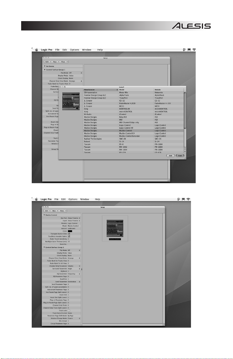
3. Select “Mackie Designs > Mackie Control > Logic Control” from the list, and click “Add” at the
bottom-right. Close the window.
4. Select “Alesis FireWire” for the Out Port and Input.
5. See the Logic notes later in this manual for details on MasterControl operation with Logic.
27
Page 30

SAMPLITUDE SETUP
1. From the menu bar, go to MIDI f MIDI Options f System Options f Hardware Controller.
2. Click the “Add New” button and select “Mackie Control” from the list.
3. Select “Alesis FireWire” for the “MIDI Input” and “MIDI Output,” and be sure “Activate Controller” is
checked.
DIGITAL PERFORMER SETUP
1. Open a new Finder window and go to Applications f Utilitiesf Audio MIDI Setup.
2. Click on the “MIDI Devices” tab, then click the “Add Device” button.
3. Double-click on the new device and name it “MasterControl.”
4. Select “Mackie” as the manufacturer and “Mackie Control” as the model. Apply these changes.
5. Connect the “Alesis FireWire” interface to this new device by clicking and dragging your cursor
from the output of the “Alesis FireWire” to the input of the “MasterControl” and the output of the
“MasterControl” to the input of the “Alesis FireWire.”
6. Open Digital Performer.
7. Go to Setup f Control Surface Setup.
8. Click the + button. Select “Mackie Control” as your driver and “Mackie Control > Mackie Control”
as your MIDI device.
PRO TOOLS SETUP
1. From the menu bar, go to Setup f Peripherals f MIDI Controllers.
2. Select “HUI” from the drop-down list.
3. Set the “Receive From” and “Send To” to “Alesis FireWire.”
4. Note that, under Pro Tools, the MasterControl can only function as a control surface. Pro Tools
requires use of its own audio hardware.
REASON SETUP
1. From the menu bar, go to Edit f Preferences f Control Surfaces and Keyboards.
2. Click the “Add” button and choose “Mackie” from the drop-down list of manufacturers.
3. Set the “MIDI In Port” and “MIDI Out Port” to “Alesis FireWire.”
SOUNDTRACK PRO SETUP
1. From the menu bar, go to Soundtrack Pro f Preferences f Control Surfaces.
2. Click the + button and choose “Mackie” from the drop-down list of manufacturers.
3. Set the “Input” and “Output” to “Alesis FireWire.”
28
Page 31

AUDIO INPUTS AND OUTPUTS
Channels Sent from the MasterControl to the Computer
The FireWire port sends every available individual MasterControl channel to the computer. This means
that, from the MasterControl, you can send a maximum of 26 channels: eight analog channels, 16 digital
channels over the ADAT connections, and two digital channels over
the coaxial S/PDIF connection. The number of available channels
will vary depending on (1) how you use the ADAT 2 / S/PDIF
connection and (2) the sampling rate you set.
Channels Received from the Computer into the MasterControl
The Firewire port receives 6 channels back from the computer—a
stereo audio stream for each of three channel pairs. From the
MasterControl, you can freely assign these three stereo pairs to any
of Output Sources A, B, and C as well as to Headphones 1 and 2.
If they are used, direct monitoring signals will be blended in with
these channels. Using the talkback mic will “take over” these
channels.
For more information on how these channels work and how to monitor them, refer to MONITORING &
CONTROL ROOM FEATURES.
Available Channels at Various Sample Rates
The number of inputs available to you drops as you move from the single sample rates up to the double
and then quadruple rates.
At single rates (44.1kHz and 48kHz), you can use:
8 analog channels (the MIC / LINE and LINE INPUTS)
2 coaxial S/PDIF channels (the RCA S/PDIF INPUT)
8 ADAT channels (the ADAT 1 INPUT)
8 ADAT channels or 2 optical S/PDIF channels (the ADAT 2 / S/PDIF INPUT)
At dual rates (88.2kHz and 96kHz), you can use:
8 analog channels (the MIC / LINE and LINE INPUTS)
2 coaxial S/PDIF channels (the RCA S/PDIF INPUT)
4 ADAT channels (the ADAT 1 INPUT)
2 optical S/PDIF channels (the ADAT 2 / S/PDIF INPUT)
At quad rates (176.4kHz and 192kHz), you can use:
8 analog channels (the MIC / LINE and LINE INPUTS)
All of the outputs—three stereo pairs, plus the two headphone outputs—are always available in all
sample rates.
All digital audio carried over
the FireWire connection is 24bit PCM data.
You can use either of the two
FireWire ports on the back of
the MasterControl. The other
port can be used to attach
another FireWire-based
computer peripheral, such as
an external hard drive.
29
Page 32

WINDOWS AUDIO CONFIGURATION
CHOOSING THE MASTERCONTROL AS YOUR DEFAULT AUDIO DEVICE
To use your MasterControl as your default Windows sound device, follow these steps:
1. From the Windows Start menu, choose Control Panel.
2. Choose Sounds and Audio Devices (XP) or Sounds (Vista).
3. Click the “Audio” tab. Change the default devices for both sound playback and sound recording to
“Alesis FireWire Audio.” If you will be using MIDI, select “Alesis FireWire MIDI” from the MIDI
music playback menu.
4. Click the “Voice” tab. Change the voice playback and voice recording settings to the “Alesis
FireWire Audio” option.
5. Click “Apply” to apply these changes.
30
Page 33

DISABLING WINDOWS SYSTEM SOUNDS
Windows System Sounds – the sounds that Windows plays to signal starting up, shutting down, alerts
and so forth – can interfere with your audio recording. We strongly suggest disabling these sounds.
1. Click the “Sounds” tab of Sounds and Audio Devices (XP) or Sounds (Vista). Under the “Sound
Scheme” drop-down menu, choose “No Sounds.”
2. Click “OK” to accept this entry and close the dialog box.
31
Page 34

p
ALESIS FIREWIRE CONTROL PANEL (WINDOWS)
Open the Alesis Firewire Control Panel from the shortcut on
your Desktop, the Programs menu, or from within your audio
application.
1 2
3
4
5
To open the control panel within
Cubase in Windows, go to Devices f
Device Setup… f VST MultiTrack,
then under the “ASIO Alesis Firewire”
Device, click the “Control Panel”
6
9
7 8
1. Selecting the Alesis MasterControl: Be sure that your MasterControl is shown here. If it is not
shown, then your computer does not “see” it. Check the mixer’s connection to your computer.
You can chain multiple Alesis Firewire devices together via their Firewire ports. If you do so, you
must choose one of them, here, as the clock master for your entire system.
2. Setting the Mixer Nickname: You can change the name of the mixer as it’s seen by the
recording program on your particular computer. Once this is done, choose “Reset All” in Cubase’s
Devices/Device Setup window (or the equivalent command in other programs) to make the change
to the mixer flow down to the names of the input and output channels.
3. Specify the Audio Clock Source:
y Internal: Use this setting if you are using the MasterLink
on its own, without any ADAT or S/PDIF input devices.
y FireWire: Use this setting if you have another FireWire
audio device connected to the MasterControl and you
want that device’s clock to drive the MasterControl’s
clock. No additional cables are necessary—the
MasterControl will read the clock signal coming from the
If you’re using the
MasterControl by itself, you
don’t need to worry about
clocking. Just make sure that
the “Clock Source” parameter
in the MasterControl’s control
anel is set to “Internal.”
other device over the FireWire cable.
y ADAT and S/PDIF options: Use an appropriate setting here if you are using an external
ADAT or S/PDIF analog-to-digital converter.
32
Page 35

4. Adjusting the sample rate: You can change the sample rate that the MasterControl uses in this
area.
Some audio programs require that you change the sample rate under their Project Setup or
similar menus. For instance, Cubase will take control of this parameter.
5. Adjusting latency by changing the buffer size: “Latency”
refers to the amount of time it takes for audio to get into and
out of the computer. In the best of all possible worlds, there
would be no such thing as latency – we would hear audio the
moment it was created. However, computers have limited
processing power, and they can “choke,” cut off recording, or
crash programs if they are asked to handle too much data all at
once.
To minimize this risk, audio can be stored in a buffer for a
certain amount of time. This buffering helps smooth out the stream of data that the computer
needs to handle. In the end, all of the audio is sorted out and played correctly, but with a delay.
Here are the basic considerations to consider when adjusting buffer sizes:
In digital recording systems, all
digital input devices must be
synchronized to the same
clock. Use word clock cables
or other connections to
synchronize multiple external
converters, if you are using
them.
y Lower buffer size = less latency but higher risk of audio problems
y Higher buffer size = more latency but lower risk of audio problems
y Very high buffer size = possible system instability
For most systems, there is a “sweet spot” where latency is not too high and system performance is
good. Experiment with raising or lowering buffer sizes to hit this sweet spot.
As you begin adding plug-in EQ, compression, and so forth to
your project, your computer will need to work harder. If you
start to hear clicks, pops and other glitches in your audio,
consider increasing your buffer size at this time.
As a final note, one tremendous benefit that the MasterControl
offers is that you can monitor through it without latency at all.
Press the DIRECT MONITOR button (and mute the input monitoring in your DAW) to hear what
you’re recording without any delay between the incoming and monitored signal.
6. Specify how sample rates can change: Since Windows (and various Windows applications)
have a nasty tendency to try and take control over your audio sample rate – often without notice –
this section allows you to ignore those sample change events.
If you do not mind your sample rate changing freely, choose “Allow SR Changes.”
To allow only ASIO applications (like Cubase) to change the sample rate, select “Allow ASIO
changes only.”
You can lock the sample rate – such that it can only be changed using this control panel – by
selecting “Apps cannot change SR.” This is the safest of all these options.
Whichever setting you choose, the sample rate can always be changed from within this control
panel. Note, however, that if you have an audio application open, you can cause conflicts with it if
you try to set the sample rate differently here compared to the setting in the open audio
application.
7. Enable or disable WDM Audio (Windows only): If you are using ASIO applications exclusively
and do not need access to Windows system sounds, Windows Media Player or other media
players, consider un-checking this box. Doing so helps ensure that unwanted audio from other
applications does not intrude on your intended audio output.
8. Specify the System Sounds Configuration: These buttons will call up other windows where you
can set the configuration of input and output channels of the MasterControl. The default will be
“Stereo,” though the number of channels on the MasterControl allow for a variety of configurations
ranging from mono to 7.1 surround sound. The channels available in each drop-down menu in the
window will depend on the option selected in the “MultiChannel Config” menu.
9. Specify the System Latency Compensation: If you are experiencing system instability,
experiment with these settings in order to find the best combination of buffer size and latency
compensation. Note that, if you choose an option other than “none,” the lowest buffer sizes will not
be available.
Many people use two latency
settings—a lower one when
recording tracks and a higher
one when mixing.
33
Page 36

y
MAC AUDIO CONFIGURATION
AUDIO MIDI SETUP
On Mac, after you install the drivers, open the Audio MIDI Setup
utility.
Choose “Alesis Firewire” for your “Default Input” and “Default Output”
devices under Mac’s Audio MIDI Setup utility.
Audio MIDI Setup is available
from your Mac’s Applications /
Utilities folder.
You may want to drag Audio
MIDI Setup to your dock, so
ou can access it easily.
Also, choose your clock source, and set your sample rate here.
34
Page 37

ALESIS FIREWIRE CONTROL PANEL (MAC)
On Mac, buffer sizes are controlled by individual applications, and clocking and sample rates are set in
Audio MIDI Setup. Therefore, the Alesis Firewire Control panel—available either by pressing “Configure
Device” from within Audio MIDI setup or by choosing Preferences from your Apple (top left) menu—
provides just a few options:
General tab
1. Master Device: Ensure that your MasterControl is an option in this drop-down box. If the
MasterControl is not shown, then your computer does not “see” it. Check the mixer’s connection to your
computer.
You can chain multiple Alesis Firewire devices together via their Firewire ports. If you do so, you must
choose one of them, here, as the clock master for your entire system.
2. Specify the System Latency Compensation: If you are experiencing system instability, experiment
with these settings in order to find the best combination of buffer size and latency compensation. Note
that, if you choose an option other than “none,” the lowest buffer sizes will not be available.
Nickname tab
Every MasterControl has a unique serial number. Here, you can change your MasterControl’s name as
it is seen by this specific computer. We recommend that you change the nickname (for instance, to
“MasterControl”).
Additionally, your MasterControl’s firmware version is shown on this tab, towards the bottom. Check
www.alesis.com
to see if a firmware update is available.
35
Page 38

<
---50%
y
GLOBAL MENUS
Press the GLOBAL button to edit the MasterControl’s
configuration, including where you want to route which channels,
talkback and footswitch settings, and other features.
Use the PAGE buttons beneath the DISPLAY to scroll through
the settings. For each page, you can scroll through your options
with the VALUE / ENTER knob at top right. To save your new
settings, press the knob.
Screen Contrast
Adjust the contrast of the DISPLAY to an appropriate setting.
Output A / B / C Source
With the Output Source pages, you can decide which pairs of channels of your digital audio workstation
(DAW) will be sent to the three outputs of the MasterControl.
Each output – A, B, and C – can receive audio from the DAW’s
Channels 1 and 2 (Output 1-2), Channels 3 and 4 (Output 3-/4), or
Channels 5 and 6 (Output 5-6). A channel pair can be sent to
multiple outputs at the same time or none at all, allowing you
flexibility when monitoring the audio in your DAW. By default, the assignments are:
y OUTPUT A SOURCE: Output 1-2
y OUTPUT B SOURCE: Output 3-4
y OUTPUT C SOURCE: Output 5-6
Note: Regardless of how you assign the Output Sources, you can still monitor the physical outputs (on
the rear panel of the MasterControl) with the MasterControl’s SPEAKERS / OUTPUTS buttons. You can
assign what audio is sent to these outputs in your DAW. Your headphones can always monitor any of
these channel pairs, as well, as determined by the Phones Source pages (below).
Phones 1/2 Source
Use the Phones Source pages to decide which pairs of channels
of your DAW will be sent to each HEADPHONE OUTPUT (on the
rear of the MasterControl). Like the Output Sources above, a
channel pair can be sent from the DAW to one, both, or neither of
the HEADPHONE OUTPUTS.
1-2 LEVEL knob operation
By default, this knob controls the levels for outputs 1 and 2 for any of the line outputs that are mapped to
them in the OUTPUT A / B / C Source menus.
You can change this control here to affect not only 1-2 but also 3-4. A third option, designed for 5.1
surround mixing, allows this knob to control all of the outputs (1-6) as played through the
MasterControl’s six line outputs.
Note: If you are going to turn off
the MasterControl after saving a
global setting, wait at least five
seconds first. Some global
settings are not saved
immediatel
.
SCREEN CONTRAST
--->
OUTPUT A SOURCE
Output 1-2
PHONES 1 SOURCE
Output 1-2
36
Page 39
Y
Y
10%
ADAT
Control Surf
Positi
P
Direct Monitoring
When the MasterControl’s Direct Monitoring function is enabled,
the signal you are hearing is taken directly from the MasterControl
rather than from your DAW. This allows you and your musicians
to monitor the audio with no perceptible delay (latency). Here, you
can choose whether or not the Direct Monitoring signal will be blended with the signal from the DAW in
each channel pair.
You can adjust the blend of the Direct Monitoring signal with the
DAW’s output by turning the DIRECT MON LEVEL knob. At 0%, you
will hear only the DAW’s output. At 100%, you will hear the Direct
Monitoring signal at an equal volume with the DAW’s output. In the
latter case, you may hear the input signal twice, with a short delay
between each instance (“slapback”). To hear the Direct Monitoring
signal alone, simply turn off the input monitoring in your DAW.
Talkback
Pressing the MasterControl’s TALKBACK button will activate the
built-in microphone above it, which you can use to talk to your
musicians. When you select “Yes,” the talkback signal will cause
the DAW’s outputs to be muted (so talkback can “override”
whatever else is coming over the headphones or monitors). When you select “No,” the TALKBACK
button will have no effect.
Note: You will not be able to use talkback while recording at 176.4kHz and 192kHz.
Talkback Volume
This setting determines the volume of the talkback signal.
Optical Port 2
The ADAT 2 / S/PDIF port on the rear panel of the MasterControl
can accept either ADAT or optical S/PDIF information, which you
can select here.
Footswitch Setup
When a footswitch is attached to the FOOTSWITCH connection
on the rear panel of the MasterControl, it can be set to operate on
the control surface or act as the TALKBACK button.
Footswitch Polarity
This setting changes the polarity of a connected footswitch. The
default is “Positive On,” meaning the pedal, when pressed, will
activate or engage whatever it is set to. Selecting “Negative On”
will configure it such that it will be on as long as the pedal is not
being pressed.
Send SysEx
Access this page to download a SysEx file to the MasterControl to
change the configuration of its Editable Controls for its various
Presets. Select which Preset this will affect by turning the PUSH
SELECT knob. You can select any of the 12 Presets or the global
configuration (“GLOBL"):
DIR. MON ON 1/2
es
Note: At 176.4kHz and
192kHz, you can only use
the MasterControl’s direct
monitoring function on the
Output Source A – or
Channels 1 / 2.
TALKBACK ON 1/2
es
TALKBACK VOLUME
OPTICAL PORT 2
FOOTSWITCH SETUP
ace
FOOTSWITCH POLAR
ve On
SEND SYSEX PRE 1
ress to send
37
Page 40

R
Factory Reset
Activating a Factory Reset will restore all default settings and
Preset configurations. If you want to reset, select “Reset all.” You
will be asked, “You sure?” If you want to continue, select “Yes.”
The DISPLAY will read “Resetting” with two asterisks moving
across the screen to indicate its progress.
When the reset is complete, the MasterControl will reboot itself
automatically.
FACTORY RESET
eset all
FACTORY RESET
Resetting**
38
Page 41

a
MONITORING & CONTROL ROOM FEATURES
Speakers / Outputs Controls
The SPEAKERS / OUTPUTS buttons allow you to monitor the MasterControl’s MON / LINE OUTPUTS
as follows:
y The “A” SPEAKERS / OUTPUTS button monitors the “A” outputs (Channels 1 and 2)
y The “B” SPEAKERS / OUTPUTS button monitors the “B” outputs (Channels 3 and 4)
y The “C” SPEAKERS / OUTPUTS button monitors the “C” outputs (Channels 5 and 6)
You can monitor any of these three outputs individually or simultaneously. Note that the channel pairs
mentioned above simply refer to the stereo channels (L and R) on the rear panel of the MasterControl,
not the channels in your DAW. You can decide what channels from your DAW are sent to these outputs
in the OUTPUT SOURCE page in the Global Menu.
The 1-2 LEVEL knob controls the volume sent out of the analog outputs for any of the analog output
pairs that are set to listen to DAW outputs 1/2. If you wish to adjust the levels of other channels, you will
have to do so within your DAW. This knob will not affect the volume levels of the HEADPHONE
OUTPUTS (which are actually controlled by the HEADPHONE 1 and 2 knobs underneath it).
Headphone Controls
The HEADPHONE 1 and HEAPDHONE 2 knobs control the volume of the signal sent to the respective
HEADPHONE OUTPUTS on the MasterControl’s rear panel. (These controls act independently from
the SPEAKERS / OUTPUTS buttons and the 1-2 LEVEL knob.) You can decide what channels from
your DAW are sent to these outputs in the PHONES SOURCE page in the Global Menu.
Talkback Controls
Pressing the TALKBACK button allows you to talk to your musicians
over the built-in microphone above the button. When using talkback,
the microphone’s signal will “override” whatever else is coming over
the speakers (that is, the MasterControl’s Output A, B, and/or C) and
the headphones. You may hear a “click” when you press or release
the TALKBACK button, which is normal. If you want to avoid this, use an external footswitch (and set it
to control the talkback feature in the Global Menus).
You can set which output channels talkback affects and at what volume, in the Global Menu. Make sure
the appropriate SPEAKERS / OUTPUTS buttons are activated when using talkback – if your musicians
can’t hear that output, they won’t hear talkback either.
Note: You will not be able to
use talkback while recording
t 176.4kHz and 192kHz.
39
Page 42

DIRECT MONITORING
The MasterControl contains a hardware-based, DSP mixer which enables you to route the inputs to the
outputs directly, bypassing any latencies associated with sending the audio to and from the computer.
This hardware-based routing provides the minimum possible latency – only the time required for audio to
be converted between analog and digital formats and then back again to analog. This time is essentially
imperceptible (just a few milliseconds at 44.1kHz, half of that at 88.2kHz, and a quarter of that at
176.4kHz).
When to Use Direct Monitoring
When you are recording simpler projects that put less strain on your computer, you can generally
choose lower buffer settings in the Alesis Firewire control panel. When your buffer sizes are low
enough, you can use the input monitoring feature of your DAW recorder, and the latency (delay)
experienced by your performers will be very slight. Using such low buffer settings, you may find use of
the MasterControl’s direct monitoring feature to be unnecessary.
However, when you add more tracks and plug-ins, you will need to increase your buffer sizes in order for
your system to keep operating smoothly. At this point, it makes sense to mute the input monitoring on
your DAW and use the MasterControl’s digital mixer.
Configuring the GLOBAL menus
In the Global menus, choose whether you want to hear the direct signal via the MasterControl’s MON /
LINE OUTPUT pairs 1/2, 3/4, and/or 5/6.
Creating a Direct Monitoring Mix
Press the DIRECT MONITOR button on the left side of the MasterControl. The button will light, and the
faders will snap to their Direct Monitoring positions. Press the BANK LEFT (<) and BANK RIGHT (>)
button to access the following outputs:
y Analog Outputs (Tracks 1-8)
y ADAT1 (Tracks 1-8)
y ADAT2 (Tracks 1-8) or Optical S/PDIF (Tracks 1-2)
y Coaxial S/PDIF (Tracks 1-2)
In each bank, adjust the volume using the faders. Adjust the pan position using the knobs. Press MUTE
or SOLO on the Master Control’s surface to mute or solo individual tracks. Press SELECT to center any
channel’s pan position.
Raise or lower the overall Direct Monitoring mix with the DIRECT
MON LEVEL knob.
Whenever you exit the Direct Monitoring Mode, your settings (fader
placement, pan position, and the DIRECT MON LEVEL amount) will
be saved automatically.
Special Considerations at Double- and Quad-Speed Sample Rates
At dual rates – 88.2kHz and 96kHz – the first optical port’s inputs are
halved, from eight ADAT channels to four channels. The second
optical port only operates as an optical S/PDIF input at these rates;
ADAT is disabled. To avoid hearing glitches in the input audio
caused by data mismatches, disconnect any ADAT devices from the
second optical port at 88.2kHz and 96kHz.
At quad rates – 176.4kHz and 192kHz – both the digital inputs and talkback become unavailable. At
these rates, direct monitoring is only available to outputs 1/2, not outputs 3/4 and 5/6.
Note that the levels set here
will be different from the levels
returned from your DAW, if you
have your DAW’s direct
monitoring (echo) feature
enabled.
You can adjust all eight faders
in the various banks,
regardless of the sample rate.
The settings you assign will be
used when you use lower
sample rates.
40
Page 43
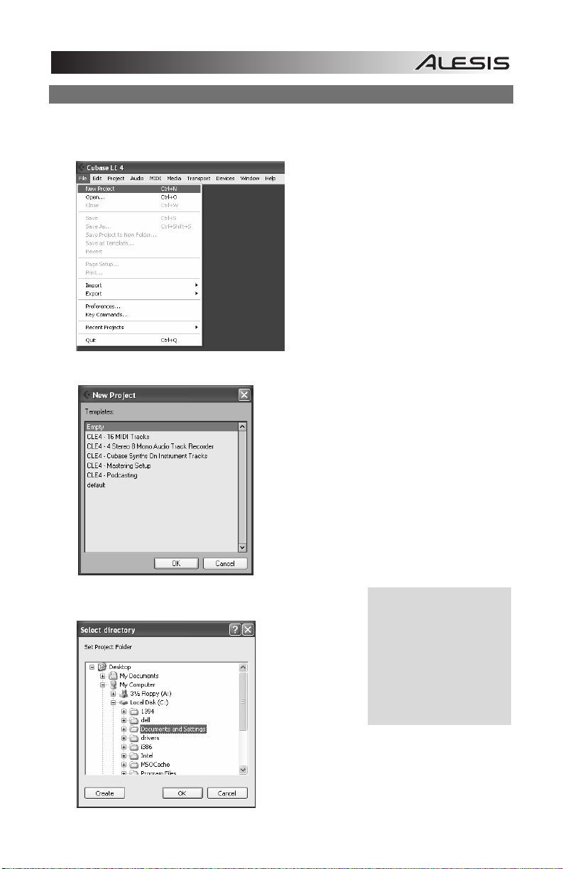
CREATING A CUBASE LE PROJECT FOR RECORDING
Once you have set up Cubase to work with the MasterControl, you’re ready to create an audio project.
1. Choose File f New Project.
2. You can begin with a template or an empty file. For now, begin with an empty file.
3. Cubase needs to know where to place audio. Choose a
directory here.
An excellent scheme for
storing your projects is to
create a directory called “audio
projects.” Then, within that
folder, create a new folder for
each song you work on.
Cubase will store your song
file and all associated audio
files (in a folder called “Audio”)
in that same folder.
41
Page 44

4. Now, you have a blank project. Add an audio track for recording by choosing Project f Add
Track f Audio.
5. Be sure that the “inspector” – a strip on the left-hand side of
Cubase that shows all sorts of information about the selected
track – is active. If your view is similar to that shown below, the
Inspector is active. If you do not see all of the information on
the left-hand side, the Inspector is not active. To activate it,
press the “Show Inspector” button towards the upper left of the screen (just below the Edit menu in
the following picture).
Later, you can hide the
Inspector if you want to save
space on your screen.
42
Page 45

6. Choose an input for your track by selecting it from the drop-down menu of available inputs. By
default, the input will be the first stereo bus in the “VST Connections” window.
7. You will do most of your monitoring through the mixer. However, if you want to monitor with
Cubase’s effects, or if you just want to hear what the computer is hearing, press the direct
monitoring button next to the Record Enable button.
Note that using the MasterControl’s direct monitoring causes a small delay as the digital audio is
being processed. For this reason, when you use direct monitoring, you may want to mute
Cubase’s input monitoring so as not to hear the audio signal twice.
Add additional audio tracks as needed. Record-enable each one and press the RECORD button
to begin recording.
For additional information, consult your software’s documentation.
43
Page 46

IMPORTANT POINTS FOR USERS OF VARIOUS DAWS
When using the MasterControl with various Digital Audio Workstations (DAWs), you will find the control
surface interacts slightly differently with some of them. This is normal! This section lists the kinds of
control surface behavior that are unique to certain DAWs, using their current versions at the time of this
writing.
Some important notes:
y Button operations F1 through F8, and Shift-F1 through Shift-F8, refer to control surface (Mackie
Control) functions. These functions are not the same as those on your regular ASCII keyboard.
y Open your DAW only after you select the proper Preset on the MasterControl. If your DAW’s
controls seem out of sync with the MasterControl, reset the control surface from your DAW.
y If you use the wrong MasterControl preset with a DAW program, the communication between
your computer and the MasterControl may appear to be behaving correctly in the DISPLAY but
actually be incorrect.
CUBASE / NUENDO
y When using a footswitch, assign it to “User A.” To use the footswitch, you will need to assign a
function to “User A” under Cubase’s/Nuendo’s “Mackie Control” setup screen.
y The SCRUB button does not work in Cubase LE4.
y If you use the < BANK > or < TRACK > buttons when Rows 2 or 3 are selected, the LEDs next to
each row may flicker briefly, which is normal.
y By default, Cubase/Nuendo will record arm the last track touched. You can disable this behavior
by going to Preferences and navigating to Preferences> Edit> Project &Mixer. There, uncheck
“Enable Record on Selected Track.”
y Be sure to choose “Mackie Control” as the control surface. Do not select “Mackie HUI,” as HUI’s
protocol is incompatible with the MasterControl’s Cubase / Nuendo preset.
ABLETON LIVE
y While Live is in Arrange mode, SCRUB mode moves the playhead. While Live is in Session
Mode, SCRUB scrolls vertically instead.
y Row 3 (“Input”) is page 4/4 in Live’s I/O menu. Choose “Auto-Selection” in Live for this page to be
properly selected. Pressing the third ROW SELECT button repeatedly on the MasterControl will
allow you to see the intermediate display states.
CAKEWALK SONAR
y To make the MasterControl’s MASTER FADER control more than just the left output, click the
LINK (lock) icon in the console (mixer) view on SONAR’s master fader.
y The MasterControl’s REW / FF buttons have different functions while in Loop, Select, Punch, and
Marker Modes in Sonar.
y Loop Mode: REW or FF jumps to the left or right boundary of the loop, respectively.
y Select Mode: REW or FF jumps to the left or right edge of the selection, respectively.
y Punch Mode: REW or FF jumps to the Punch In or Punch Out points, respectively.
y Marker Mode: REW or FF jumps to the left or right marker on the timeline.
44
Page 47

LOGIC PRO
y Ensure that you choose a “Mackie Control” control surface. The “Logic Control” control surface
uses a different set of MIDI messages and is not compatible with the Alesis MasterControl.
y Rows 2 and 3 on the MasterControl correspond to different modes in Logic:
Row 2 is Send Mode. Four “Send Parameter” options are selectable within Logic for this row:
1. Destination (incompatible with the MasterControl)
2. Level (dB)
3. Position (Pre-/Post-)
4. Mute (Active/Muted)
We suggest choosing “Level” or “Position” for this parameter. “Destination” (the default in Logic)
will not work with the MasterControl.
If zoom mode is not enabled on the MasterControl, you can use the up and down arrows around
the jog/shuttle wheel to navigate amongst the available sends in this row.
Row 3 is CSParam Mode. Eight "Channel Strip Parameter" options are selectable within Logic for
this row:
1. Volume
2. Pan
3. Format
4. Input (incompatible with the MasterControl)
5. Output (incompatible with the MasterControl)
6. Automation Mode
7. Group
8. Displayed Parameter
"CSParam" is re-assignable. The default is “Volume.” We recommend using "Format," which can
turn effects on and off, or “Automation Mode,” which cycles through the various automation options
for the selected track.
If zoom mode is not enabled on the MasterControl, you can change the parameter that you are
affecting by using the left and right arrows around the jog/shuttle wheel in this row.
y “Write” is used to turn automation on. Automation can only be defeated in Logic by pressing the
“Read” button. “Read” toggles between “on” and “off.”
y By design, the MasterControl’s MASTER fader can control Logic’s MASTER output. However,
Logic does not automate this channel. For bi-directional control over the output level, use Logic’s
OUT 1-2 fader, which appears as an ordinary channel within the right-most bank of your Logic
project.
SAMPLITUDE
y Press the Knob Row 2 and Knob Row 3 buttons repeatedly for different options available for these
rows. The printed overlays provide only one of the different options available for each of the two
knob rows.
y For the third row, which controls individual channel EQ, the first page controls the EQ
parametrically. The first two bands are assigned to the knobs. Press BANK > to access the last
two bands. Double-click on the EQ icon in the mixer or the arrange view to see the entire view of
the parametric EQ. The second page operates as indicated on the included overlay.
45
Page 48

DIGITAL PERFORMER
y Row 2 of the MasterControl is not mapped.
y Vertical Zoom is not possible from the MasterControl.
y MasterControl’s ZOOM button cycles through three stages (as opposed to two on most other
DAWs): unlit, lit, and flashing. It will be lit when it is on and unlit when it is off. When the button is
flashing, no zoom functions are possible using the cursor buttons.
y Grouping and ungrouping faders must be done within the Digital Performer software. This cannot
be done from the MasterControl.
ALESIS HD24 / HD24XR
y This preset allows one-way control from the MasterControl to an Alesis HD24 or HD24XR.
y COMPUTER CONNECTION: This preset requires you to connect the MasterControl to a
computer via Firewire, as normal.
y MIDI CABLE CONNECTIONS: Using standard MIDI cables, connect the HD24’s MIDI OUT to the
MasterControl’s 5-pin MIDI IN. Connect the MasterControl’s 5-pin MIDI OUT to the HD24’s MIDI
IN.
y Use a MIDI utility application to route the MasterControl’s:
o control surface MIDI OUT data out of the 5-pin MIDI OUT port.
o 5-pin MIDI IN data to the control surface’s MIDI IN.
The following illustration shows this routing using the free Windows program MIDI-OX:
y Ensure that your MIDI utility application is set to pass SysEx information in both directions. If you
are using MIDI-OX, enable its Pass SysEx feature from the bottom of the Options pull-down menu.
y Ensure that you set the "Send MMC" parameter to "Yes" on the HD24's MIDI01 utility page.
y This preset allows you to use the transport controls and jog wheel with the HD24.
o The SELECT buttons exclusively record-arm any one of the HD24’s channels 1-
8.
o The RECORD buttons exclusively record-arm any one HD24 channel 9-16.
o The SOLO buttons exclusively record-arm any one HD24 channel 17-24.
o The MUTE buttons record-arms pairs of channels (1-2, 3-4, 5-6, 7-8, 9-10, 11-12,
13-14, or 15-16).
y The MasterControl’s SELECT/RECORD/SOLO/MUTE buttons and transport control buttons never
light. Additionally, the faders and knobs are not operational.
y Via this preset, the HD24 does not respond to disarm messages but rather only to a master
message setting the REC ARM status of all 24 tracks at once. So, for example, if you have record
enabled tracks 1-8 and you want to "disarm" tracks 1-4, issue a command to "REC ARM 5-8". That
will disarm all other tracks except for 5-8, including tracks 1-4. Press EDIT to choose various
options for the ASSIGNABLE buttons to arm and disarm multiple specific tracks.
46
Page 49

PRO TOOLS
y JOG is unavailable in Pro Tools. This is a limitation of the HUI protocol used by Pro Tools.
Pressing the SCRUB button puts the JOG WHEEL into Scrub Mode.
y When scrubbing, if you want your cursor to remain at the last scrub point in the timeline, go to
Setup>Preferences>Operation>Transport and check "Edit Insertion Follows Scrub/Shuttle." This
is necessary if you wish to use an edit function such as SEPARATE in conjunction with the jog
wheel.
y When you add tracks in Pro Tools, including at the very start of a project, Pro Tools appears to
lock out the track selection buttons on the MasterControl. To make the buttons functional again,
hold one SELECT button and press another; then press one of the BANK or TRACK buttons.
REASON
y You may want to lock the mixer to “Mackie Control” Mode when using Reason. To do this, right-
click on the left side of the mixer and choose the appropriate option.
y Only the bottom row of the MasterControl’s DISPLAY will show data.
y The TRACK buttons function in Reason, but the BANK buttons are not functional
SOUNDTRACK PRO
y The MasterControl’s < TRACK > buttons do not function in Soundtrack Pro.
y The LEDs for the SELECT buttons do not function in Soundtrack Pro, but they will still select the
channel.
47
Page 50

PLUG-IN 1, 2
y These presets are designed to control virtual instruments and effects plugins. If you are using a
virtual instrument within a DAW, you will need to disconnect the Alesis Firewire MIDI ports from
control surface operation (Mackie Control or HUI) so that you can use the MasterControl as a
generic MIDI controller.
In these presets:
o The eight channel faders are mapped to CC 12-19.
o The Master fader is mapped to CC 20.
o The knobs are mapped to CC 22-29.
o The SELECT/REC/SOLO/MUTE buttons are mapped to CC 102-117.
On the first channel strip:
• SELECT sends NOTE ON for CC 102.
• REC sends NOTE OFF for CC 102.
• SOLO sends NOTE ON for CC 103.
• MUTE sends NOTE OFF for CC 103.
Similarly, the second channel strip begins with CC 104, and the
eighth (last) channel strip ends with CC 117.
o The ASSIGNABLE buttons are mapped to CC 01, 02, 30, 31 (bank A) and CC
41, 41, 43, 66 (bank B). Similar to channel strip operation, the TOP button
always sends a NOTE ON, and the BOTTOM button always sends the
corresponding NOTE OFF message.
y In PLUG-IN 1, the ASSIGNABLE buttons can be mapped to the values above or any CC values
from 46-90, inclusive.
y In PLUG-IN 2, the ASSIGNABLE buttons can be mapped to the values above or any CC values
from 84-117, inclusive. Switching between these two presets allows you access to more CC’s
than would be available using only a single preset.
y Consult your virtual instrument’s or effect’s documentation to learn how to map the MasterControl’s
MIDI messages to your software’s controls.
48
Page 51

SIGNAL FLOW DIAGRAM
49
Page 52

SPECIFICATIONS
Microphone preamplifier
Gain range: +9.1dB to +59.2dB
Impedance: 3.67K @ min gain; 3.33K @ max gain
Line preamplifier
Gain range: -7dB to +43.1dB
Maximum input signal levels before clipping
Mic In to Line Out:
Line In 1-2 Max input signal level before clipping (at midband frequencies):
Line In 3-6 Max input signal level before clipping: +17.8dBu typical
Frequency Response
Line Inputs 1-6 (Measured to Line Output at Unity Gain):
Mic Inputs 1-2:
Total Harmonic Distortion + Noise, Signal-to-Noise
Mic Input 1-2 to Line Out (measurement bandwidth 20-22K):
Line Input 3-6 to Line Out (20 measurement bandwidth 20-22K):
Dimensions
MasterControl only (without power adapter, packaging):
Weight
MasterControl only (without power adapter, packaging):
7 pounds, 12 ounces
3.5 kilograms
Note: Specifications accurate at time of manual creation. Specifications are subject to change without
notice.
At min gain: 9.6dBu in, 18.7dBu out (gain = 9.1dB)
At max gain: -40.5dBu in, +18.7dBu out (gain = 59.2dB)
At unity gain: 18.7 to 18.9dBu
At min gain: 25.7 to 25.9dBu
At max gain: -24.4 to -24.2dBu
-.25dB at 20KHz, otherwise within ±0.1dB
At min gain: +/- 0.1dB from 20Hz to 20kHz
At gain= 30dB: +0dB, -0.25dB from 20Hz to 20kHz
At max gain: Rolls off to -1.25dB at 20Hz, otherwise flat within 0.1dB
At min gain with +10dBu output:
At 30dB gain, +10dBu output:
At unity gain, +4 to +10dBu out:
19.125” long x 14.5” deep x 3.75” high
486mm long x 368mm deep x 95mm high
THD+N: 0.0022- 0.0025%
SNR: 103.3dB
THD+N: <
SNR: 102.7dB
THD+N: <
SNR: 104.1dB
0.004%
0.004%
50
Page 53

TRADEMARKS
All trademarks are the property of their respective owners. Specifically:
“MasterControl” is a trademark of Alesis, LLC.
“Soundtrack,” Soundtrack Pro,” “Logic,” Logic Pro,” “CoreAudio,” “CoreMIDI,” “Mac” and “Mac OS” are
trademarks of Apple, Inc.
“Windows,” “Windows XP,” and “Windows Vista” are trademarks of Microsoft Corporation.
“SONAR” is a trademark of Twelve Tone Systems, Inc.
“Digital Performer” is a trademark of Mark Of The Unicorn.
“Cubase,” “Nuendo,” “ASIO,” and “VST” are trademarks of Steinberg Media Technologies GmbH.
“Mackie,” “Mackie Control,” and “HUI” are registered trademarks of LOUD Technologies, Inc.
“Reason” is a registered trademark of Propellerhead Software.
“Pro Tools” is a registered trademark of Digidesign, Inc.
“Live” is a registered trademark of “Ableton AG.”
CONTACT INFORMATION
Alesis Contact Information
E-mail: support@alesis.com
Web site: http://www.alesis.com
DEMO MATERIALS
Velocity- "I Can't Wait"
http://www.myspace.com/velocityrhyme
Vocals by Velocity
Written by Velocity and McKay Garner
Produced, recorded and mixed by McKay Garner
http://www.mckaygarner.com
Ten After 11- "Denial"
http://www.myspace.com/tenafter11
Vocals and guitars by Scott Hofman
Drums, bass, and more guitars by McKay Garner
Written by Scott Hofman and McKay Garner
Produced, recorded and mixed by McKay Garner
http://www.mckaygarner.com
Copyright 2008, Alesis, LLC. All rights reserved
Reproduction in whole or in part is prohibited.
7-51-0272-A
Manual written by Kellen Yamanaka, Fred Morgenstern
09/2008
51
Page 54

Page 55

Page 56

www.alesis.com
 Loading...