

Page 1

ALESIS
Studio 12R
Reference Manual
Page 2

Table of Contents
TABLE OF CONTENTS
Table of Contents.................................................................1
Important Safety Instructions................................3
Safety symbols used in this product............................................................3
Please follow these precautions when using this product:....................3
Introduction.............................................................................5
The Alesis Studio 12R Microphone Preamplifier/Mixer......................5
Using this manual..........................................................................................5
Grounding Instructions.................................................................................6
Installation...............................................................................7
Unpacking........................................................................................................7
AC power..........................................................................................................7
Grounding............................................................................................7
Use clean power..................................................................................8
Power switch........................................................................................8
Mounting..........................................................................................................8
Connections.............................................................................9
Inputs.................................................................................................................9
Cable common sense..........................................................................9
Microphone Inputs...........................................................................10
Phantom power.................................................................................11
Line-level devices (synthesizers, CD players, video)................12
TAPE IN jacks....................................................................................14
Phonograph turntables....................................................................15
Do not connect any of the following to any input of the
Studio 12R!.........................................................................................15
How to connect effect devices and signal processors............................16
Effects via Aux Send and Aux Return.........................................16
In-line processing using the INSERT jacks (compressors &
equalizers)...........................................................................................17
Outputs............................................................................................................20
To a stereo PA system or instrument amplifier.........................20
To a mono system.............................................................................20
To a stage monitor (foldback) system...........................................20
To another mixer..............................................................................21
To a stereo tape recorder..................................................................21
To an ADAT multitrack recorder..................................................22
Phones.................................................................................................25
Monitor Out.......................................................................................25
Studio 12R Reference Manual 1
Page 3

Table of Contents
Operating Instructions......................................................27
Before turning the mixer on, "zero out' the controls...........................27
Setting input trim levels.............................................................................28
PEAK LED method ...........................................................................28
Metering/Unity Gain method.......................................................29
Typical Fader and Control Levels..............................................................30
Proper gain staging of other equipment ......................................31
AUX System: Effects Send/Receive .........................................................32
How to Set Aux Send and Return Levels....................................32
Using the meter.............................................................................................34
Avoiding noise..............................................................................................35
System noise (ground loops, hum, induced noise)...................35
Applications...........................................................................39
Multitrack recording ....................................................................................39
Tracking/Overdubbing....................................................................39
Mixdown.............................................................................................40
Using the HIGH and LOW EQ controls ...................................................41
Monitoring AUX 1 in the PHONES jack .................................................42
Troubleshooting.................................................................. 43
Troubleshooting Index................................................................................43
Maintenance/Service...................................................................................45
Exterior cleaning...............................................................................45
Obtaining Repair Service................................................................45
Specifications....................................................................... 47
Frequency Response.....................................................................................47
Connectors......................................................................................................47
Levels...............................................................................................................48
Impedance......................................................................................................48
Noise performance (typical) .......................................................................49
Distortion (THD+N).....................................................................................49
Power...............................................................................................................49
Mounting........................................................................................................49
Dimensional Drawing ........................................................50
Block diagram ...................................................................... 51
Level diagram................................................................................................52
Index ........................................................................................53
Warranty ............................................................................... 54
Studio 12R Reference Manual 2
Page 4
Important Safety Instructions
IMPORTANT SAFETY
INSTRUCTIONS
Safety symbols used in this product
This symbol alerts the user that there are important operating and
maintenance instructions in the literature accompanying this unit.
This symbol warns the user of uninsulated voltage within the
unit that can cause dangerous electric shocks.
Please follow these precautions when
using this product:
1. Read these instructions.
2. Keep these instructions.
3. Heed all warnings.
4. Follow all instructions.
5. Do not use this apparatus near water.
6. Clean only with a damp cloth. Do not spray any liquid cleaner onto the
faceplate, as this may damage the front panel controls or cause a
dangerous condition.
7. Install in accordance with the manufacturer's instructions.
8. Do not install near any heat sources such as radiators, heat registers,
stoves, or other apparatus (including amplifiers) that produce heat.
9. Do not defeat the safety purpose of the polarized or grounding-type plug.
A polarized plug has two blades with one wider than the other. A
grounding-type plug has two blades and a third grounding prong. The
wide blade or the third prong are provided for your safety. When the
provided plug does not fit into your outlet, consult an electrician for
replacement of the obsolete outlet.
Studio 12R Reference Manual 3
Page 5

Important Safety Instructions
10. Protect the power cord from being walked on or pinched, particularly at
plugs, convenience receptacles, and the point where they exit from the
apparatus.
11. Use only attachments or accessories specified by the manufacturer.
12. Use only with a cart, stand, bracket, rack, or table designed for use with
professional audio or music equipment. In any installation, make sure
that injury or damage will not result from cables pulling on the apparatus
and its mounting. If a cart is used, use caution when moving the
cart/apparatus combination to avoid injury from tip-over.
13. Unplug this apparatus during lightning storms or when unused for long
periods of time.
14. Refer all servicing to qualified service personnel. Servicing is required
when the apparatus has been damaged in any way, such as when the
power-supply cord or plug is damaged, liquid has been spilled or objects
have fallen into the apparatus, the apparatus has been exposed to rain or
moisture, does not operate normally, or has been dropped.
15. This unit produces heat when operated normally. If this unit is installed
in a rack, make sure that there is proper ventilation when operated. Do
not operate with the rack covers on. If there are other units in the rack
that generate a large amount of heat, spread them apart. Do not
sandwich this product between to large heat-producing units.
16. This product, in combination with an amplifier and headphones or
speakers, may be capable of producing sound levels that could cause
permanent hearing loss. Do not operate for a long period of time at a
high volume level or at a level that is uncomfortable. If you experience
any hearing loss or ringing in the ears, you should consult an audiologist.
Studio 12R Reference Manual 4
Page 6

Introduction
INTRODUCTION
The Alesis Studio 12R Microphone
Preamplifier/Mixer
The Alesis Studio 12R is a high-quality, rack-mountable 12-input,
stereo output audio mixer. It is designed to handle eight
microphones, two stereo line inputs, and to route signal to and
from external effect processing devices. As a basic, easy-tounderstand mixer, it can be used in a wide variety of applications
from sound reinforcement to multitrack recording. It may also be
used as an accessory or submixer to a larger console.
Using this manual
To get the most out of your Studio 12R, please read this manual.
While the mixer is not complicated to operate, the manual contains
information that will help you get the highest level of performance
from it. We’ve included creative alternative techniques that aren't
obvious at first glance.
To find what you need quickly, refer to the index at the back of the
manual, or the Table of Contents.
We appreciate your feedback. If you have any suggestions on how
to improve this manual, please write to us at:
Technical Communications Dept.
Alesis Corp.
3630 Holdrege
Los Angeles, CA 90016
or via email at: alecorp@alesis1.usa.com
Conventions
The buttons, knobs, and rear panel connectors are referred to in this
manual just as their names appear on the Studio 12R, using all
capital letters (Example: [TRIM] control, [PAN] knob, [PHONES]
jack, etc.).
✪ When something important appears in the manual, an icon (like
the one on the left) will appear in the left margin. This symbol
Studio 12R Reference Manual 5
Page 7

Introduction
indicates that this information is vital when operating the Studio
12R.
Grounding Instructions
This product must be grounded. If it should malfunction or break
down, grounding provides a path of least resistance for electric
current to reduce the risk of electric shock. This product is equipped
with a cord having an equipment-grounding conductor and a
grounding plug. The plug must be plugged into an appropriate
outlet that is properly installed and grounded in accordance with all
local rules and ordinances.
DANGER - Improper connection of the equipment-grounding
conductor can result in a risk of electric shock. Check with a
qualified electrician or serviceman if you are in doubt as to whether
the product is properly grounded. Do not modify the plug provided
with the product; if it will not fit the outlet, have a proper outlet
installed by a qualified electrician.
Studio 12R Reference Manual 6
Page 8

Installation
INSTALLATION
Unpacking
The Studio 12R box should contain:
1. The mixer itself
2. A packet of literature along with this manual
3. An AC power cable
4. An Alesis warranty card
Please send in your warranty card right away. Your warranty is not registered
with Alesis until the card is returned. Please save your sales receipt as your ultimate proof
of purchase and warranty date. By sending in your warranty card, you will receive the
Alesis First Reflection magazine free of charge, and we will be able to notify you of special
programs and offers from Alesis. Should repair ever become necessary, having the unit
registered will make it faster and easier to obtain service.
Note that the warranty is valid only in the country of purchase; i.e., units purchased in the
United States must be serviced in the United States.
AC power
READ ALL SAFETY WARNINGS IN THE PREVIOUS SECTION OF THIS MANUAL
TO ENSURE SAFE OPERATION OF THIS UNIT. Connect the Studio 12R to the
specified power using the AC cable supplied with the unit. The AC cable is removable. If
the distance to your AC outlet is longer or shorter than the supplied cable, you may
substitute an approved standard NEMA-to-CEE power cable of the correct length, available
from most electronics stores.
Grounding
CONNECT THE STUDIO 12R TO A PROPERLY GROUNDED OUTLET ONLY. DO
NOT USE ADAPTERS WHICH REMOVE THE SAFETY GROUND PROTECTION OR
CUT OFF THE GROUNDING PRONG ON THE POWER CORD. Proper grounding is
essential for user safety and low noise. If you experience 60-cycle hum in your sound
system as a result of different ground potentials between different units in your system,
plug all units into the same AC circuit (if the total power load allows) and make sure other
devices in the system are properly grounded themselves. The Studio 12R features balanced
inputs and outputs, so if it is properly connected to other balanced units, AC ground
potentials will not affect the audio. If you cannot get rid of ground loops, consult a
professional electrician familiar with sound system power designs.
Use clean power
The Studio 12R's internal power supply is designed to filter out most AC line noise.
However, it is still good practice to plug your sound equipment into an AC circuit that is
not shared with lighting dimmers, refrigerators, air conditioning units, or other appliances
that may induce noise into the power system.
Studio 12R Reference Manual 7
Page 9

Installation
Power switch
The POWER switch is located on the back panel. A power indicator
is on the front panel next to the meter. Avoid turning the power
switch on or off while the Studio 12R is connected to a live
amplifier.
Mounting
The Studio 12R may be rack mounted in a standard EIA 19" rack, occupying three standard
1.75" rack spaces. Any angle of orientation is acceptable. Note that (as with most audio
equipment) if it is mounted into metal rack rails, the chassis ground of all units in the rack
will be connected together by the rail. In some cases this is desirable, but if hum is a
problem in the system, you may need to install non-conductive rack screws and washers on
the Studio 12R or other equipment in the rack to isolate the chassis grounds from each
other.
The mixer may also be used on a table top. To avoid scratching a tabletop surface, apply
rubber or felt feet to the bottom of the Studio 12R.
Studio 12R Reference Manual 8
Page 10

Connections
CONNECTIONS
Inputs
Cable common sense
Make all connections to the Studio 12R with the power turned off wherever
possible. If you must connect or disconnect inputs while power is on, make sure the
channel fader and [TRIM] are turned all the way down to avoid sudden pops and clicks
which may damage speakers or other equipment.
Use good-quality cable: 99% of all mixer problems turn out to be
cable or connector problems. Use the best quality cable you can, for
highest reliability and lowest noise. If something goes wrong, check
the cable and its connection to the mixer first. If the connectors are
dirty or corroded, clean them with isopropyl alcohol or other
approved electrical contact cleaner before inserting them into the
Studio 12R. High quality cables are low-capacitance shielded cables
with a stranded (not solid) internal conductor and a low-resistance
shield. Although quality cables cost more, they do make a
difference.
Route cables in your system correctly by observing the following
precautions:
• Do not bundle audio cables with AC power cords.
• Avoid running audio cables, or placing the Studio 12R itself,
near sources of electromagnetic interference such as
transformers, monitors, computers, etc.
• Never unplug a cable by pulling on the wire itself. Always
unplug by firmly grasping the body of the plug and pulling
directly outward.
• Do not place cables where they can be stepped on. Stepping on a
cable may not cause immediate damage, but it can compress the
insulation between the center conductor and shield (degrading
performance), or reduce the cable’s reliability.
• Avoid twisting the cable or having it make sharp, right angle
turns.
Microphone Inputs
The Alesis Studio 12R features eight studio-grade, low-noise hybrid microphone
preamplifiers. These [MIC] jacks are designed to work with almost any low-impedance
Studio 12R Reference manual 9
Page 11

Connections
Balanced Mic Input
microphone using standard 3-conductor XLR connectors. The [MIC] jacks also feature 48
volt phantom power, which may be turned on and off by the [PHANTOM] switch on the
back panel, for condenser microphones which require external powering.
12
3
Cold
Socket (female)
GroundHot
The MIC Input is designed to accept a wide range of balanced or unbalanced low
impedance input signals, with up to 60 dB of amplification available (which is 10 to 20 dB
more than many other rack-mount mixers). It is wired with "pin 2 hot" according to the
accepted standard.
✪ Use only one input per channel. The LINE IN jack and the MIC IN jack of a
channel can’t be used at the same time. If you turn up the level of a line source to hear it at
the same time a microphone is connected, you may damage the microphone.
Studio 12R Reference manual 10
Page 12

Connections
Phantom power
Certain types of microphones (called condenser microphones) require a DC power supply
from the mixer. “Phantom power” sends 48 volts of DC through the microphone cable. If
any of your microphones need phantom power, turn on the [PHANTOM POWER] switch
on the Studio 12R’s back panel to connect all the XLR MIC IN jacks to the Studio 12R’s
internal 48 volt phantom power source. Since the power is applied equally to pins 2 and 3,
phantom power should not affect dynamic microphones (which do not require phantom
power). However, make sure that your microphone cables have no short circuits or
intermittent connections to avoid damage to the system.
✪Avoid connecting or disconnecting any microphones while [PHANTOM
POWER] is turned on. Make all connections with the Studio 12R powered off. If this
is not possible, make sure the channel's fader and [TRIM] are down, make the
connections, then turn on the [PHANTOM POWER] switch on the back panel before
bringing the fader and [TRIM] back up. Many microphones make a loud "pop" when first
powered, so make sure your faders are down to avoid damaging your speakers or hearing.
Never connect the MIC jack to an UNBALANCED source or to a
line-level device (such as a tape recorder or synthesizer) when
phantom power is being used.
If none of your microphones need phantom power, leave the phantom power switch off.
Studio 12R Reference manual 11
Page 13
Connections
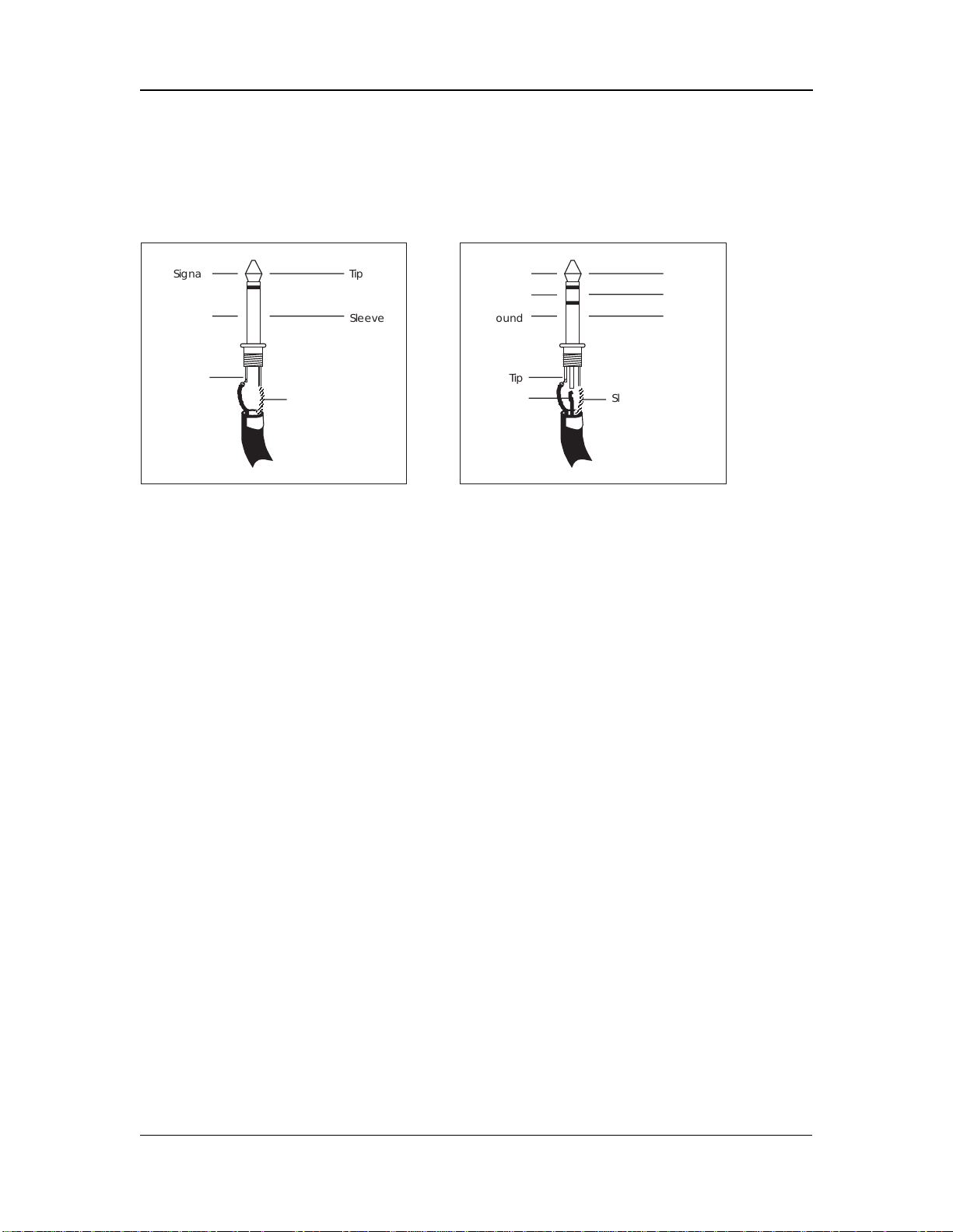
Unbalanced Line Input
Balanced Line Input
Line-level devices (synthesizers, CD players,
video)
The Studio 12R features line-level inputs on 1/4" phone jacks which accept standard
unbalanced or balanced signals.
Signal
Ground
Tip
Sleeve
Tip
Sleeve
Hot
Cold
Ground
Tip
Ring
Tip
Ring
Sleeve
Sleeve
Unbalanced -10 dBV line level sources: Most synthesizers, drum machines, effect
devices, cassette decks and CD players operate at this level. Their average signal level is
about 1/3 of a volt. They have a 2-conductor output jack that is either a 1/4" phone or
"RCA phono" type. These may be plugged directly into any of the Studio 12R’s [LINE
IN] jacks, with the [TRIM] level set at approximately the 1 o'clock position. Plug stereo
sources such as synthesizers, CD players, and drum machine main outputs into the
STEREO LINE channels (9/10 and 11/12) if possible.
Electric guitars and basses may be plugged directly into the [LINE IN] jacks, if you
raise the [TRIM] level. The Studio 12R has more than enough gain (up to 50 dB when the
channel fader and trim are set to maximum) for guitars, although some pickups may sound
better if they're plugged directly into a high-impedance preamp designed for guitar use.
Plug the output of such preamps into any [LINE IN] jack.
A reminder: do not plug a line input and a microphone input into the same
channel. The inputs are not designed to handle two sources at the same time. If you
crank up the line level input to extremes to compensate for the level loss, you may damage
the microphone.
Studio 12R Reference manual 12
Page 14
Connections
Balanced +4 dBu line level sources: Professional recording and processing
equipment typically provides a balanced, 3-conductor signal output that is a higher voltage
(1.24 volts nominal level) than most synthesizers and stereo equipment. The Studio 12R’s
[LINE IN] jacks are designed to handle these balanced inputs.
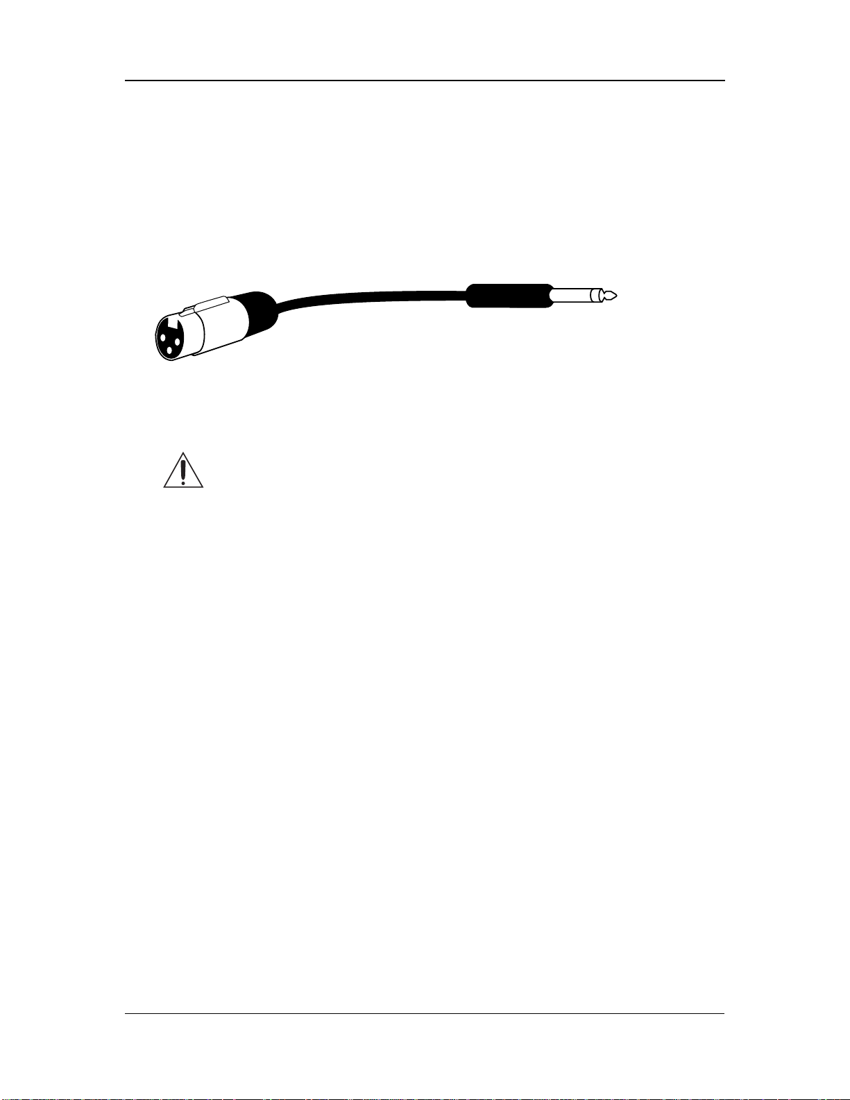
Balanced sources often feature XLR outputs. However, they should NOT be connected to
the XLR [MIC] inputs of the Studio 12R unless absolutely necessary, because the higher
gain of the MIC jacks gives you less headroom than the LINE IN jacks do (also, the source
could be damaged by phantom power if it's turned on). Connect them to the [LINE IN]
jacks using an XLR-to-1/4 inch phone TRS (tip-ring-sleeve) cable, as shown below:
If the proper connector cable or adapter is not available, +4 dBu line level sources may be
connected to the [MIC] jacks ONLY IF PHANTOM POWER WILL NOT BE
USED!!
Connecting a line-level output to a phantom-powered XLR input
on the Alesis Studio 12R may cause damage to the external unit.
Alesis cannot be responsible for any damages caused by this kind of
misuse.
The nominal trim setting for a +4 dBu signal plugged into a line input is approximately 11
o'clock (12 o'clock on the stereo channels). This will give you plenty of headroom to start
with.
Maximum levels: The maximum level the [MIC] jack can receive with the [TRIM]
control full counter-clockwise is +12 dBu before clipping, so there’s only 8 dB of
headroom if you plug a +4 dBu line source into the mic jack. The [LINE IN] jack on
channels 1-8 may receive levels up to +32 dBu without clipping, a headroom advantage of
20 dB. The stereo channels may receive a +22 dBu (balanced or unbalanced) maximum
input.
Studio 12R Reference manual 13
Page 15

Connections
TAPE IN jacks
The [TAPE IN] jacks on the rear panel are designed for playback of a
stereo tape deck (or any other -10 dBV level signal) through the
[MONITOR OUT] and [PHONES] jacks only. A signal at the [TAPE
IN] jacks cannot be heard from the [MAIN OUT] jacks.
This allows you to use the Studio 12R to monitor a mixdown to a 2track deck through your headphones. (If you plugged your
mixdown deck into the line inputs on the channels, it would cause
feedback when you press “record”.) By placing the
[PHONES/MONITOR] switch in the TAPE position, you will hear
the mixer's output after it has been passed through the mixdown
deck, so you can make sure that it is recording correctly.
•
Another use for the [TAPE IN] jacks is to play a CD or tape into a
PA system, automatically turning off all the microphones into
the main PA system when the front panel MSTR/TAPE switch
is set to the TAPE position. Note that in this application, the PA
system must be fed from the MONITOR OUT instead of the
MAIN OUT jacks, and will be affected by the level of the
[PHONES/MONITOR] control as well as by the [MASTER]
control fader.
Studio 12R Reference manual 14
Page 16

Connections
Phonograph turntables
If you're using a record turntable, you may not plug it directly into the line inputs of the
Studio 12R (well, you can, but it will sound very thin and noisy). Obtain a phono preamp
from your dealer or an electronics specialty store.
1. Plug the outputs of the phonograph pickup into the RIAA-
equalized phono preamp.
2. Plug the outputs of the preamp into the LINE IN 9-10 or 11-12
inputs of the Studio 12R.
Do not connect any of the following to any
input of the Studio 12R!
• The speaker output of any power amplifier.
• Any source that is too loud for the input (no more than 3 volts
RMS into a [MIC] jack or 13 volts RMS into a [LINE IN] jack).
• Any unshielded cable.
Studio 12R Reference manual 15
Page 17
Connections
How to connect effect devices and signal
processors
Alesis and other companies make many different types of signal processors which may be
connected to the Studio 12R mixer. There are two ways to connect these units: using the
AUX system or via the INSERT jacks.
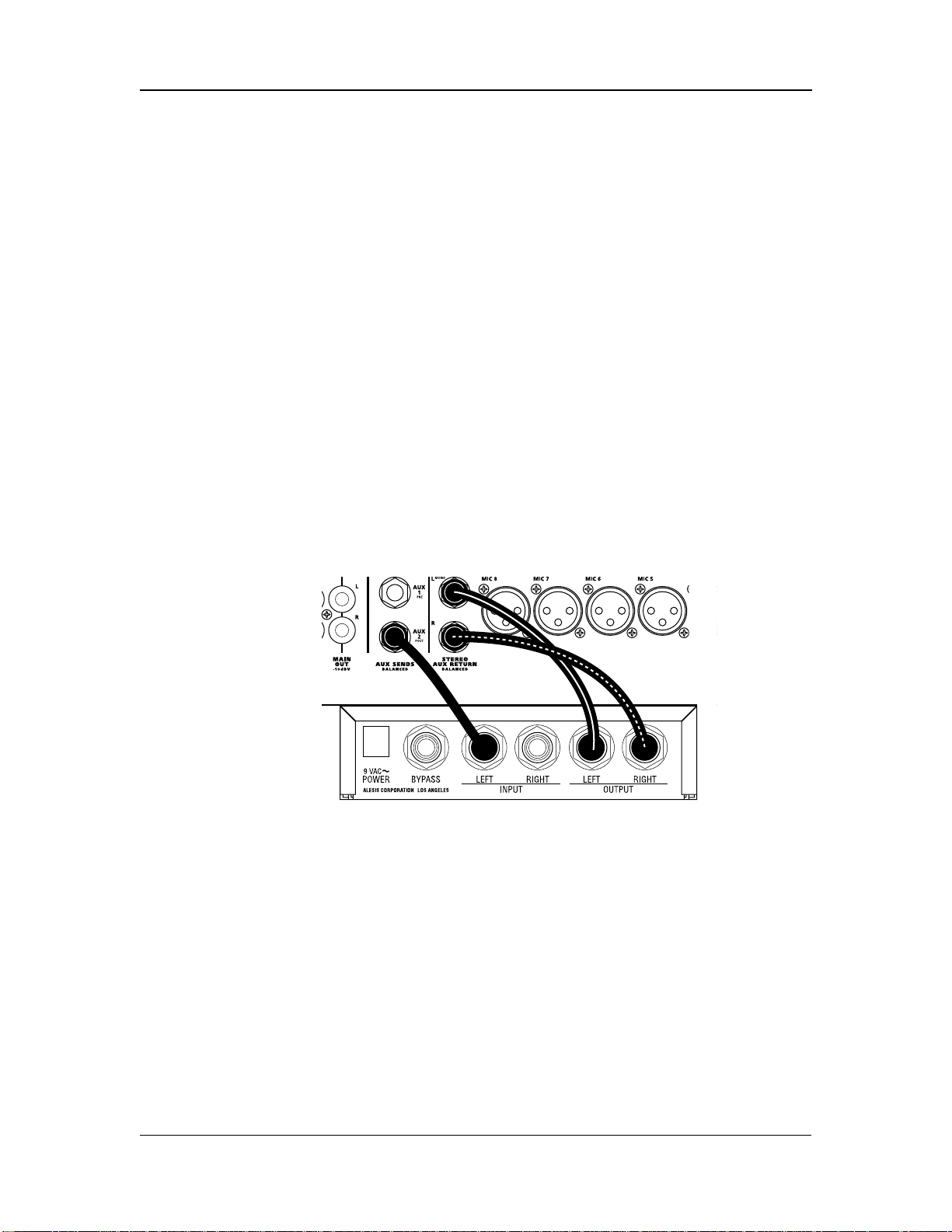
Effects via Aux Send and Aux Return
If you want to add an effect such as reverb, chorus, or delay to several different inputs at
once, you will use the AUX system.
1. Connect the AUX 2 (POST) AUX SEND output of the 12R to the
input of the effect device. If the effect has a stereo input, check
the manual of the effect to see which jack is the mono jack. (In
most cases, you won't need to connect anything to the other
input jack of the device, but you will still get a stereo effect
output).
2. Connect the left and right outputs of the effect device to the
[STEREO AUX RETURN] jacks of the Studio 12R.
•
Alternatively, you may connect the output of the effect device to
either of the STEREO LINE channels ([9-10 or 11-12].) This will
allow you to control the effect with a large fader, send the effects
to the Aux 1 output for monitoring, and use EQ on the effect.
About stereo effect devices
✪ If your effect unit has two inputs, in most cases you need to connect
from only ONE Aux Send to the left (mono) input of the effect unit,
but you will still connect both the left and right outputs of the effect
to the STEREO AUX RETURN.
Studio 12R Reference manual 16
Page 18

Connections
You don’t need to connect anything to the other input of the effect,
because most effect units use the stereo inputs only to provide a
path for the “dry” stereo signal when the effect is connected directly
between an instrument and an amplifier. In mixing applications
such as with the Studio 12R, you will set the effect’s wet/dry balance
all the way to “wet” (effects only, no direct signal). The effect device
will generate an artificial stereo output from the signal input.
Check the manual for your effect device for more information.
On the other hand, true dual-channel effects processors (such as the
Alesis QuadraVerb 2) may be connected to two different sends to
take advantage of the dual processing capability. Dual-channel
processors allow the left and right inputs to be used for different
kinds of effects (for example, the left input to a stereo chorus while
the right input is used for a stereo reverb).
Using Aux 1 as an effects send
Note that [AUX 1] may also be used as an extra effects send.
Although Aux 1 is a pre-fader send, and normally used for stage
monitoring or a separate headphone mix while recording, it may
also be used as an effects send so you can add different effects to
different channels. Just remember that the “PRE” under [AUX 1]
means that when you move a fader up or down you won’t change
the level going to an effect from Aux 1. If you change fader levels,
you will need to adjust Aux 1 levels to maintain the same balance
between dry and effected signal.
In-line processing using the INSERT jacks
(compressors & equalizers)
Some signal processors are designed to be used on one signal at a time, with the entire
signal being processed instead of a mix of effected and uneffected signal. The purpose of
the INSERT jacks on channels 1-8 is to allow you to insert a compressor, equalizer, or
other effect into the signal path of a single channel after its preamplifier and [TRIM]
control, but before the Studio 12R's own EQ, aux sends, and fader. The INSERT jacks
may also be used as direct outputs to a recorder.
The INSERT connector is a TRS (tip/ring/sleeve) 1/4" jack which
consists of an insert send (the tip of the TRS plug) and an insert
return (the ring of a TRS plug). A special Y-cable consisting of a
TRS 1/4" plug on one end and two mono 1/4" plugs on the other
end is required.
Studio 12R Reference manual 17
Page 19

Connections
Insert Points
Send
Return
Ground
Tip
Ring
Sleeve
Tip
Ring
Sleeve
Note that you will not hear any signal through the Studio 12R if the
INSERT jack is plugged in and the signal is interrupted in that loop (by the
other cables being disconnected, the processor being turned off, or the volume turned off in
the processor).
Connecting an in-line processor
1. Obtain a "stereo splitter" insert cable from your dealer.
2. Connect the stereo (TRS) end to the INSERT jack of the Studio
12R.
3. Connect the mono plug from the tip connector to the input of
the processor.
4. Connect the mono plug from the ring connector to the output of
the processor.
If you're not sure which mono plug is from the tip and which is from the ring, check to see
if the cable is labeled. If not, simply try it one way and if the signal doesn't pass through,
swap the input and output plugs the other way.
•
The [INSERT] jack may also be used as a direct output to a
multitrack recorder such as the ADAT. The send from the insert
jack is where the cleanest mic preamp signal may be obtained,
without passing through the EQ or channel circuitry. Simply insert
the plug to the first "click" (the ring connector) and it will not
interrupt the flow through the mixer, while providing a direct
output. Or, put the recorder into INPUT mode and insert the plug
all the way, connecting the input and output of each track of the
Studio 12R Reference manual 18
Page 20

Connections
recorder into each channel path of the mixer. This will allow
playback monitoring of the recorder. See the Applications chapter
for more information.
For more information on using the AUX and INSERT systems, see the
“Operating Instructions” chapter of this manual.
Studio 12R Reference manual 19
Page 21

Connections
Outputs
To a stereo PA system or instrument
amplifier
Balanced
Check to see if your amplifier can accept balanced inputs. If so,
connect the [MAIN OUT BALANCED] jacks of the Studio 12R to the
input of the amp using a 3-conductor cable, with a 1/4" TRS plug on
one end, and the connector used by the amp (usually a 1/4" TRS
connector; sometimes an XLR or terminal strip) on the other.
•
You may also connect the [MONITOR OUT] jacks of the mixer to
your amplifier. This will allow you to switch between hearing 2track playback and the stereo output of the mixer, using the front
panel monitor switch.
Unbalanced
If the amp is unbalanced, use a standard shielded "patch cord" with
1/4" connectors.
To a mono system
If your PA system or amplifier isn't stereo, connect either the left or
right MAIN OUT jacks to the input of the system. Make sure that
all [PAN] controls are in the center or turned to the side you're
using.
To a stage monitor (foldback) system
If your PA system has a separate amplifier and speaker system for monitors, connect a
cable from the [AUX 1 PRE AUX SENDS] jack to the amp input, in the same manner as
above. The Aux 1 system is a pre-fader, post-EQ send with a balanced/unbalanced output.
In most stage monitor situations, we recommend connecting a third-octave graphic
equalizer such as the Alesis MEQ-230 between the mixer and the amp to control feedback.
The Aux 1 output may be connected in the same way for a number of different applications
such as:
• Headphone cue feed for multitrack recording
• Separate broadcast mix from a PA system
• Zone feed for a separate region of a PA system
Studio 12R Reference manual 20
Page 22

Connections
To another mixer
The main or monitor outputs of the Studio 12R may be connected
to a larger mixing console. Consult the manual for the other mixer
for more information. If the mixer has "SUB IN" jacks, connect to
those. Alternatively, you may simply connect the MAIN OUT or
MONITOR OUT jacks of the Studio 12R to two line-level inputs on
the other mixer. If you do, check to see what level those inputs are
designed for.
• If the inputs of the other mixer can handle +4 dBu balanced or -2
dBu unbalanced levels, simply connect the [MAIN OUT
BALANCED] outputs to the other mixer's line inputs.
• If the inputs are designed for -10 dBV level inputs (such as most
keyboard and guitar amplifiers, and consumer stereo amplifiers),
connect the [MAIN OUT -10 dBV] outputs to the line inputs of
the external mixer.
If the connection is made properly, the Studio 12R will not distort
the input of the other mixer. You may need to adjust the input
trim of the other mixer to get the best dynamic range.
To a stereo tape recorder
If you want to record the output of the mixer into a typical stereo
cassette or DAT deck, connect the [MAIN OUT -10 dBV] phono jacks
to the left and right inputs of the cassette deck using a standard
stereo phono-to-phono (RCA) cable.
If your recorder is a professional type with balanced +4 inputs, in
most cases you should connect the [MAIN OUT BALANCED] jacks
of the mixer to the inputs of the recorder.
• If you connect the [MONITOR OUT] jacks to the recorder, the
level will be affected by the [PHONES/MONITOR] level control on
the front panel. However, if you're using the [TAPE IN] jacks to
monitor playback, you run the risk of feedback if you press the
MSTR/TAPE switch while in record mode.
Studio 12R Reference manual 21
Page 23

Connections
To an ADAT multitrack recorder
The studio-grade microphone preamplifiers of the Studio 12R are
designed to rival or exceed the sound quality of external
microphone preamps costing many times more. A basic 8-track
digital recording system with an ADAT-XT and a Studio 12R is
portable, cost-effective, easy to use, and sonically transparent. There
are two ways to use the Studio 12R with ADAT: a single mixer with
the ADAT patched into the [INSERT] jacks, or using two Studio
12Rs, one for input and another for monitoring.
In-line ADAT recording:
In this hookup method, the ADAT is patched into the [INSERT] jacks of channels 1-8 as if
each track of the recorder were a signal processor in each channel of the mixer. Since the
ADAT is a unity-gain device, it will not affect the levels going through the mixer. The
[TRIM] control is the only level control for the ADAT inputs; the channel faders, EQ, and
aux sends of the Studio 12R are used for monitoring and will not affect multitrack
recording levels.
This method is recommended by many audiophiles and engineers, since there is a minimum
of circuitry between the original source and the recorder. Hooking a Studio 12R to an
ADAT via the [INSERT] jacks is effectively the same as connecting studio-quality
microphone preamps directly to the input of the tape deck.
NOTE: To hear the microphone or line input signal through the mixer, the
ADAT track must be in RECORD READY or INPUT mode. See the ADAT
manual for more details.
1. Obtain eight "stereo splitter" insert cables from your dealer.
These cables feature a three-conductor TRS ("stereo") 1/4" phone
plug at one end, and split out to two "mono" plugs at the other,
as shown below. If you have an ADAT, use 1/4" TRS to 1/4"
mono cables. If you have an ADAT-XT, use 1/4" TRS to phono
cables.
2. Connect the stereo/TRS end to the INSERT jack of channel 1 of
the Studio 12R.
Studio 12R Reference manual 22
Page 24

Connections
3. Connect the mono plug from the tip connector to the input of
the ADAT. NOTE: the ADAT’s tracks are arranged from left to
right on the back panel, and the mixer’s channels are from right
to left, so the wires will have to cross over.
4. Connect the mono plug from the ring connector to the output of
the ADAT.
If you're not sure which mono plug is from the tip and which is
from the ring, check to see if the cable box has that information.
If not, simply try it one way and play a prerecorded tape from the
ADAT. If you can't hear output from the mixer with the faders
and master up, swap the input and output plugs the other way.
5. Plug in channels 2-8 of the mixer to tracks 2-8 of the ADAT in
the same way.
INPUT
OUTPUT
1 2 3 4 5 6 7 8
LOCATE/PLAY
LRC REMOTE
PUNCH
IN/OUT
DIGITAL
OUTIN
INPUT
OUTPUT
SYNC
OUTIN
Using two Studio 12Rs for more flexibility:
The in-line method may be used for recording one source to a track. But if you want to
record a mix of microphones or other sources onto a pair of tracks, two Studio 12Rs can
do the job more quietly and in a smaller space than expensive dedicated recording consoles.
One 12R is the "source" mixer which feeds the ADAT's inputs, and the other is the
"monitor/mixdown" mixer which receives the ADAT's outputs.
1. Plug the -10 dBV MAIN OUT jacks of the "source" 12R to track
inputs 1 and 2 of the ADAT.
• Because the ADAT has normalled inputs, the stereo output of
the source mixer may be recorded on other tracks without
repatching. The left output of the mixer will appear at the
inputs of tracks 1, 3, 5 & 7; the right output will appear at track 2,
Studio 12R Reference manual 23
Page 25

Connections
4, 6 & 8. On the ADAT-XT, press and hold [ANALOG INPUT]
and the REC READY keys for track 1 or 2 to activate this "built-in
patch bay" feature.
2. Plug track outputs 1-8 of the ADAT to LINE IN 1-8 of the
"monitor/mixdown" 12R. Note that output 1 is on the left of
the ADAT, but on the right of the mixer, so the wires must cross
over.
3. To record more than two tracks at a time, plug a mono cable
from the INSERT jack of any channels of the mixer to the input
of any track. By plugging the cable all the way in the INSERT
jack, and not returning the signal from the recorder, the
individual channels will be removed from the stereo mix. This
way, you can record a stereo mix of several inputs on any two
tracks while simultaneously recording individual sources on
other tracks.
Studio 12R Reference manual 24
Page 26

Connections
Phones
The [PHONES] jack on the front panel is designed for most stereo
headphones. The internal headphone amplifier outputs the
maximum power allowed by safety standards. The impedance and
efficiency of the headphones will determine the maximum volume
available. Eight-ohm headphones may be louder at a given setting
than 150-ohm or 600-ohm headphones; however, there should be
enough gain to drive any dynamic headphone to reasonable levels,
if the mixer is being run properly.
Note that the PHONES/MONITOR level control on the front panel
affects both the headphone jack on the front panel
and the
[MONITOR OUT] balanced jacks on the back panel.
Monitor Out
The [MONITOR OUT] jacks give you a signal that will be the same
as the MAIN OUT, as long as the front panel [MSTR/TAPE] switch
is in the "MSTR" position. The only difference is that the
MONITOR OUT signal is after the front panel PHONES level
control. When that control is up full, the MONITOR OUT jack will
be 10 dB louder than the MAIN OUT. The PHONES control may be
lowered to the point where the MONITOR OUT is almost at
microphone level, low enough to be patched into the microphonelevel inputs of a camcorder or house PA system. However, connect
the monitor output to line level inputs wherever possible.
Studio 12R Reference manual 25
Page 27

Connections
Studio 12R Reference manual 26
Page 28

Operating Instructions
OPERATING
INSTRUCTIONS
Before turning the mixer on, "zero out'
the controls
To avoid surprises while you're setting up a new system, set all controls to their "zeroed
out" positions as follows before proceeding:
1. Make all connections to the Studio 12R, as described in the
previous chapter.
2. Bring all channel faders and the [MASTER] fader down to
minimum.
3. Set all [TRIM] controls to minimum (full counterclockwise).
4. Set all [AUX 1], [AUX 2], STEREO AUX RETURN,
[PHONES/MONITOR] controls to minimum (full
counterclockwise).
5. Set all [HIGH] and [LOW] EQ, [PAN], and [BAL] controls to "12
o'clock".
Studio 12R Reference Manual 27
Page 29

Operating Instructions
Setting input trim levels
✪ Proper setting of the [TRIM] controls is crucial to low-noise, distortion-free operation. If
the trim is set too high, there will be distortion even if the channel faders are low. If the
trim is set too low and the channel faders are raised to get the signal loud enough, you will
be amplifying the noise of the mixer.
Instead of doing this, get as much gain as possible as close to the signal source as possible.
If you've plugged a synthesizer or other line-level source into the Studio 12R, set its output
volume to maximum. If a microphone is the source, the Studio 12R's [TRIM] control will
determine the gain of the system.
✪ The goal is to get the signal as loud as possible as early as possible in the
signal path, without causing clipping (distortion) anywhere in the path or
in the sound system.
PEAK LED method
Each channel of the Studio 12R has its own [PEAK] indicator, which
will light when the signal level rises to within 6 dB of clipping. In
situations where the maximum signal-to-noise ratio is required
(such as digital recording), use the PEAK LED as a guide for setting
the [TRIM] control.
✪ When the PEAK LED is flashing, it does NOT necessarily mean that
distortion has occurred. There is usually some headroom left if the
PEAK LED is flashing momentarily on the loudest peaks.
1. With the sound source active, and the channel fader down to
minimum, raise the [TRIM] control until the PEAK LED flashes
occasionally on the loudest transients.
2. If desired, lower the [TRIM] control slightly until the flashing
stops.
Note for extremely high level line inputs in stereo channels: If the
[TRIM] setting is set below unity (12 o'clock position) on a stereo
channel, it is possible for the first input stage to clip without the
PEAK LED coming on. If distortion is still heard after lowering
the trim to its minimum setting, it means the source is
extremely high (+22 dBu or higher). In this case you must lower
the output level of the source, use an external pad, or repatch to
a LINE IN on channels 1-8 (which can take up to +32 dBu levels
before clipping).
Studio 12R Reference Manual 28
Page 30

Operating Instructions
Metering/Unity Gain method
This method gives you more headroom than the peak method,
while maintaining a low noise floor which will be well below the
noise of most PA or live recording environments.
1. With the mic or line level signal flowing through the channel,
set the TRIM to minimum.
2. Set the CHANNEL FADER to 0 (about 2/3 up). Set all other
channel faders to minimum (off).
3. Set the MASTER fader to 0 dB (all the way up).
4. Observe the Studio 12R's LED Meter. Adjust the [TRIM]knob
until the average signal level on the meter is about 0 dB (highest
green LED), or peaks do not exceed the +10 dB LED (or whatever
maximum your system is designed for). If you ever see the
channel's PEAK LED flash, you are within 6 dB of signal
overload. Turn down the TRIM knob until the PEAK LED stops
flashing.
Studio 12R Reference Manual 29
Page 31

Operating Instructions
Typical Fader and Control Levels
Ideally, after you have set the [TRIM] controls, both the Channel
and Master faders should be run between the -10 dB and 0 dB
position (about 1/2 to 3/4 of the way up the fader travel on the
channels, and 3/4 to full on the master) if possible. This position
gives the greatest amount of headroom and low noise. It also
allows for any additional increase or decrease in level that might be
required during mixing. Ultimately, the fader levels are dependent
on the requirements of the mix; these suggestions are only a starting
point.
Unity gain points
Unlike many other mixers, the Studio 12R's [MASTER] fader is
designed for unity gain (0) when the fader is up full, not at 3/4 or
1/2 of the travel. This allows you greater control to use the fader for
smooth, gradual fade-outs. It also discourages inexperienced
operators from using the mixer incorrectly.
The channel faders' unity gain point is at the traditional 3/4 point,
with 10 dB of gain at the full-up position.
Trim gain ranges
The amount of gain in the TRIM circuit is shown on the front
panel. On channels 1-8, the LINE input ranges from 10 dB
attenuation to 40 dB gain, a range that should cover almost any line
signal. The MIC input ranges from +10 dB to +60 dB gain, since the
very low output voltages of microphones need to be amplified a
great deal. The stereo channels' TRIM controls can be set from -15
dB attenuation to +15 dB gain. See the Level Diagram near the end
of this manual for a graphic display of the gain structure of the
mixer.
Aux Send levels
The nominal or unity gain points of the Aux 1 and Aux 2 controls
are at the “2 o’clock” position. At the full clockwise setting, they
have 10 dB of gain. However, in most applications you won’t need
that gain, if the TRIM controls have been set properly. (See “How to
Set Aux Send and Return Levels” later in this chapter for more
information.)
Studio 12R Reference Manual 30
Page 32

Operating Instructions
Proper gain staging of other equipment
The total noise performance of your system depends on proper gain
control of all the elements. A "noisy mixer" is usually a quiet mixer
in a system whose gain structure is incorrect. As a good starting
point, set most volume level controls of other equipment at 3/4 or
75% of full. This will decrease the possibility of overload distortion
and keep the amount of background noise to a minimum.
Turn down amplifier levels: In particular, don't set the input
controls of a power amplifier "wide open" if you have to run the
faders of the mixer in the bottom half of the travel (and the meter of
the Studio 12R well below the "0" mark) to keep the system from
being too loud or feeding back. It's better to run the mixer at its
normal level, and turn down the amplifier's controls for the
desired level. By turning the amplifier's own volume controls
down, you turn down the residual noise of everything that precedes
it in the signal chain, resulting in a quieter, more controllable
system.
However, if the mixer output is too loud, and the input stage of the
amplifier being used is an active circuit (instead of a passive voltage
divider type), it is possible to clip the preamp stage of the amplifier
and cause nasty distortion even if the amp level is low. Use good
judgment and consult the manual for your amplifier for more
information.
Distortion caused by EQ: If a large amount of EQ is used, it may
become necessary to decrease either the trim control, or the channel
fader, or both. The EQ is capable of adding quite a bit of gain and is a
frequent cause of overload distortion problems. The PEAK LEDs
monitor the signal after the EQ circuit, both pre and post fader.
Studio 12R Reference Manual 31
Page 33

Operating Instructions
AUX System: Effects Send/Receive
The AUX 2 buss of the Studio 12R is a post-fader send. Usually, you
will connect AUX 2 to the input of an effect device. Using a postfader send means that when you fade a channel out, its effects will
fade out also.
Using the aux send allows each channel to have its own level
control feeding the aux output (and eventually the input of the
effect device). You can make a mix of any channels you want to go
to the effects by using the individual channels’ aux send levels.
But sending signal to the effect device is only half the story. To be
heard, the output of the effect device must be returned to the mixer
and turned up in the mix before you can hear it. You have two
options for returning the effected signal to the mix:
• connecting to the STEREO AUX RETURN jack, or
• connecting to the channel LINE IN or STEREO LINE IN jacks.
Connecting to channel inputs gives you the added bonus of
panning and EQ on the effects, and the ability to send a “wet” or
effected mix to AUX 1 for monitoring.
Wet/dry mix: No matter where you connect the output of the effect
unit into the mixer, you are in control of the “wet/dry” balance
between the mixer’s channel inputs (the uneffected or “dry” signal),
and the effect returns coming from the effect device (the “wet”
signal). The output of the effect device should only contain effected
signal, and not have any uneffected or "dry" signal mixed with it
(since the dry signal is already at the mixer). Consult the manual
for the effect device to find out how to set the effect so that only
effected ("wet") signal is returned to the Studio 12R.
How to Set Aux Send and Return Levels
You must set correct levels on the mixer's individual Aux Sends
and STEREO AUX RETURN and the effect device's own controls to
get good, clean, quiet results.
✪ Improper level setting is the most common cause of noise and
distortion problems.
Studio 12R Reference Manual 32
Page 34

Operating Instructions
By having the correct level at every point in the send/return chain,
you avoid distortion by overloading and avoid noise. The most
common mistake with effect units is to have too low a level at the
send or input, then crank up the output of the processor or the Aux
return to get the effects level desired. This amplifies the noise and
wastes headroom. Here is a procedure that will give good results
with most standard equipment:
1. Set your mixer's input levels correctly, following the
instructions earlier in this chapter.
2. Turn up the channels' [AUX 2] sends to the nominal level
(marked by a heavy dot at the “2:00” position).
3. Play the source.
4. Turn up the input level control of the effect device until you see
its meter or signal LED turn red on peaks; then reduce it slightly
until the red doesn't flash. The ideal input level, for optimum
noise performance, is just below clipping. But if other
instruments will be added to the mix later, or levels are
unpredictable (as in a live show), leave yourself additional
headroom by turning the input level down a bit more.
5. The output level of the effect device should be set at or near its
maximum in most cases, unless distortion occurs.
6. Turn up the [STEREO AUX RETURN] level until you get the
desired level of effect in the mix. The one control in the chain
that may need to be set to a low level is the Aux Return (or
channel) on the mixer. Here is where you should increase or
decrease the overall effect level in the mix, for best low-noise
performance. If you want "just a hint" of reverb, don't turn
down the Aux 2 send; turn down the Aux Return. Leave the
input levels of the effect device where they were set in step 4,
unless you see the device's overload indicator flash.
Studio 12R Reference Manual 33
Page 35

Operating Instructions
Using the meter
The meter of the Studio 12R is a fast peak type that reads in decibels,
normally displaying the level of the [MAIN OUT] jacks. When the
meter reads "0", the main outputs are at the nominal level: the
phono jacks at -10 dBV (.316 volts) and the 1/4" jacks at +4 dBu (1.24
volts) balanced, or -2 dBu unbalanced.
Use this reference level to calibrate your system. The input controls
of analog recorders should be set so that “0” on the mixer's meters
equals “0 VU” on the recorder's meters. Digital recorders use a
different reference; for example, an ADAT connected to the Studio
12R's outputs will read "-15 dB" at nominal output, if you connect
to the proper input jacks (balanced to balanced, or unbalanced to
unbalanced).
The meter follows the [MSTR/TAPE] switch, but not the
PHONES/MONITOR level control. Whatever you hear in the
headphone output, the master output (up position) or the 2-track
tape input (down position) is what the meter is reading.
Output distortion
The Studio 12R has plenty of headroom, but eventually every
electronic device reaches its limit. At +18 dB over nominal level,
the top LED of the meter labeled PK will light; at this point there is 6
dB of headroom before the master electronics will clip. Final
clipping is reached at 24 dB over nominal "0" on the meter; this
represents a level of +28 dBu at the MAIN OUT jacks if balanced,
+22 dBu if unbalanced, and +14 dBV at the MAIN OUT -10 dBV
phono jacks. Even if no channel PEAK LEDs are on, with extreme
settings of the faders it may be possible to overdrive the output to
this level.
✪ As long as the meter of the Studio 12R is below its top LED, and the
PEAK LEDs of all channels are off, the mixer should not be causing
distortion. If you hear distortion, check other devices in the signal
chain for overload, and make sure the STEREO channels' PEAK
LEDs do not come on when their TRIM is set to 12 o'clock.
Studio 12R Reference Manual 34
Page 36

Operating Instructions
Avoiding noise
If the Studio 12R is being run as suggested above, the noise of the mixer itself will not be a
significant factor in the noise level of your system, since the Studio 12R generates much
less noise than the typical source does. Noise is present in every system, analog or digital;
as operator it's your job to run the system (and particularly the mixer) so that the noise isn't
amplified unnecessarily. But the Studio 12R cannot remove noise that is already there. If a
low-level source with a poor signal-to-noise ratio is amplified by the TRIM and channel
fader, the noise will be amplified with the desired signal. A system is no quieter than its
noisiest component.
System noise (ground loops, hum, induced
noise)
In today’s studio, with dozens of different pieces of equipment and
computers, there are many opportunities for ground loop problems
to occur. These show up as hums, buzzes or sometimes radio
reception and can occur if a piece of equipment “sees” two or more
different paths to ground, with one of the paths going down a signal
line. While there are methods that can virtually eliminate ground
loops and stray radio frequency interference, such as installing a
separate power source just for the sound system, most problems are
easier to solve. Here are some basic techniques that you should use
to keep stray hums and buzzes to a minimum.
➀ KEEP ALL ELECTRONICS OF THE SOUND SYSTEM ON THE
SAME AC ELECTRICAL CIRCUIT. Most 60-cycle hums happen
because different components of a sound system are plugged into
outlets of different AC circuits. If any noise-generating devices
such as air conditioners, refrigerators, neon lights, etc., are
already plugged into one of these circuits, you then have a
perfect condition for stray buzzes as well. Since most electronic
devices of a sound system don’t require very much power
(except for power amplifiers), it’s usually safe to run a multioutlet box or two from a SINGLE wall outlet and plug in all of
the components of your system there.
➁ KEEP AUDIO WIRING AS FAR AWAY FROM AC WIRING AS
POSSIBLE. Many hums come from audio cabling being too near
AC wiring or the power transformers ("wall warts") used by
equipment requiring an external supply. If a hum occurs, try
moving the audio wiring around to see if the hum ceases or
diminishes. If it’s not possible to separate the audio and AC
wiring, make sure that the audio wires don’t run parallel to any
AC wire (they should only cross at right angles, if possible).
Studio 12R Reference Manual 35
Page 37

Operating Instructions
➂ TO ELIMINATE HUM IF THE ABOVE HAS FAILED:
A) Disconnect the power from all outboard devices and tape
machines except for the mixer and control room monitor
power amp.
B) Plug in each tape machine and outboard effect device one at a
time. If possible, flip the polarity of the plug of each device
(turn it around in the socket) until the quietest position is
found.
C) Make sure that all of the audio cables are in good working
order. Cables with a detached ground wire will cause a very
loud hum!!
D) Keep all cables as short as possible, especially in unbalanced
circuits.
If these basic experiments don’t uncover the source of the problem,
consult your dealer or a technician trained in proper studio
grounding techniques. In some cases, a “star grounding” scheme
must be used, with the mixer at the center of the star providing the
shield ground on telescoping shields, which do NOT connect to the
chassis ground of other equipment in the system.
Note that the Studio 12R is grounded through its AC cable. Signal
ground is connected to chassis ground, which in turn may be
grounded again by the rack rails. But since almost all of the inputs
and outputs of the Studio 12R are balanced, the ground does not
have to be made part of the signal path unless you are connecting to
unbalanced equipment. If the Studio 12R is mounted in a metal
rack, the mixer shares a common ground with the other equipment
in the same rack. In some cases (such as a star ground scheme), you
may need to use nonconductive rack rails or rack isolators to avoid
ground loops.
To avoid the possibility of electric shock, never defeat the safety
ground found on other equipment in the system. When in doubt
about proper electrical grounding schemes or the power to your
system, consult a qualified, licensed electrician.
Telescoping shield: In fixed installations using balanced outputs
where the amplifier is more than 20' from the mixer and on a
different AC power panel, it may be advisable to disconnect (or
"float") the shield at the amplifier end. This keeps the ground
potential of the amp rack from being conducted back to the mixer.
Even though the mixer-to-amp connection is balanced, any
Studio 12R Reference Manual 36
Page 38

Operating Instructions
unbalanced sources or effects plugged into the mixer may exhibit a
hum when the amp's ground is carried back to the mixer.
Studio 12R Reference Manual 37
Page 39

Operating Instructions
Studio 12R Reference Manual 38
Page 40

Applications
APPLICATIONS
Multitrack recording
See the "Connections" chapter for information on how to connect the Studio 12R to an
ADAT or other multitrack recorder.
In the most common setup, the ADAT is patched into the INSERT points of each channel.
It receives signal directly from the [TRIM] control; no other controls will affect the level
being recorded to tape.
Tracking/Overdubbing
1. Put the desired tracks of the ADAT into record ready mode.
Press "Auto Input Monitor" or "All Input Monitor" depending
on your situation (see the ADAT manual for more information).
2. With the signal source (microphone or line input) active, slowly
increase the [TRIM] level of each input while watching the
ADAT meter until the top red segment comes on. Then turn
down the trim level so that the red LED does not light.
3. Set the EQ, aux, and channel faders for the desired control room
mix. Note that none of these settings will affect the signal going
to the ADAT.
4. For overdubbing, put the original tracks into safe mode. These
tracks will play back through the same channels they were
recorded on.
5. If necessary, repatch the microphone or line inputs to the next
channels you want to record. NOTE: the ADAT and ADAT-XT
can automatically "normal" the input to track 1 to any oddnumbered track, and the input to track 2 to any even-numbered
track. Check the manual of the ADAT or XT for more
information.
Studio 12R eference Manual 39
Page 41

Applications
Mixdown
You may leave the ADAT connected to the INSERT jacks for
mixdown; there's no need to repatch to the LINE IN jacks.
Make the connections according to the procedure in the
"Connections" chapter.
1. Connect the MAIN OUTs (-10 dBV or +4 dBu, depending on the
deck) to the inputs of the mixdown deck.
2. Connect the outputs of the mixdown deck to the TAPE IN jacks.
3. Connect the [MONITOR OUT] jacks to the inputs of your control
room monitor amplifier.
4. Press the [PHONES/MONITOR] switch down so it is in the TAPE
position.
5. Put the mixdown deck into record/pause mode, play the ADAT,
and adjust the mix and level controls of the mixer for the
desired level. Set the MASTER fader up to the maximum, and
adjust the input controls of the mixdown deck until its meters
give the desired reading. You will also be able to see the levels
on the mixer itself; check to make sure the output of the
mixdown deck is set to nominal (unity gain).
By monitoring through the mixdown deck, you'll be able to hear if there is any distortion in
that deck's electronics.
Studio 12R eference Manual 40
Page 42

Applications
Using the HIGH and LOW EQ controls
The Studio 12R provides standard shelving EQ controls on each
channel. The HIGH knob range is +/- 15 dB with a shelving
frequency of 12 kHz. "Shelving" means that all frequencies above
12 kHz will be boost or cut by the same amount , and frequency
response between 1 kHz and 12 kHz will gradually rise or fall to the
shelving point. The LOW knob range is +/- 15 dB at a shelving
frequency of 80 Hz. This means that frequencies below 80 Hz will be
boosted or cut by the same amount, and frequency response will
gradually rise or fall from 80 Hz to about 1 kHz. The frequency
response range is shown in the curve below:
+15 dB
-15 dB
20 Hz 100 Hz 1 kHz 10k 20k
✪ The normal position for the EQ controls is "12 o'clock" or straight
up. A "click" or detent will be felt at this position. At this position,
the EQ does not affect the frequency response of the channel--it is
"flat".
Use only the amount of EQ necessary to achieve the desired effect.
Excessive boost on either EQ section may cause clipping in the
channel electronics, and will amplify noise.
Studio 12R eference Manual 41
Page 43

Applications
Monitoring AUX 1 in the PHONES jack
If you are using AUX 1 as a monitor feed, you may want to check
that mix using the headphones. If you've connected the PA or
recorder to the MAIN OUTPUTS, and are not using the TAPE IN
jacks, use Y-cords to connect the AUX 1 SEND to the TAPE IN
jack(s) at the same time it feeds the monitor amplifier. Use the
front panel [PHONES/MONITOR] switch to select between the
main and aux 1 feeds.
Studio 12R eference Manual 42
Page 44

Troubleshooting
Symptom
Cause
Solution
The Power LED does
not light when the
unit is powered on.
No power.
Check that the power
cable is plugged in
properly.
Sound is distorted,
red “PEAK” LED is lit.
Input level is too
high.
Turn down the
source volume, or
turn down the TRIM
control.
Don’t plug line level
signals into the MIC
jacks.
Sound is excessively
noisy, faders must be
raised to full to hear.
Input level is too
low.
Turn up the TRIM
control.
Se t th e source(s) to a
hi gher lev el.
Sound from effect is
noisy.
AUX 2 send level is
too low and Stereo
Aux Return on
mixer is up full.
Turn Output of effect
device up and reduce
Aux Return level on
mixer. Increase Aux
Send levels.
No audio is heard
from PHONES or
MONITOR output.
Monitor switch is
set to “TAPE”.
Se t switch to " MST R"
No audio on an
individual channel.
INSERT jack is
connected to a
device that’s off.
Ch eck insert j ack cables
an d de v ice .
TRIM level is too
low.
Tu rn t he T RIM control
up.
MIC IN and LINE
IN jacks being used
on the same
channel.
Un plug one of the
so urces fr om th e
channel.
Microphone
requires phantom
power.
Turn PHANTOM
switch on (on rear pan el
next to POWER)
TROUBLESHOOTING
Troubleshooting Index
If you experience problems while operating the Studio 12R, please
use the following table to locate possible causes and solutions before
contacting Alesis Product Support or your dealer for assistance.
Studio 12R Reference Manual 43
Page 45

Troubleshooting
Hum or noise from
output.
Ground loop,
unshielded cables.
Tr y pl u ggi n g t he u n it
in to anoth er power jack
or dif
No meter, although
audio is heard
through main
outputs.
Monitor switch is
set to “TAPE”
Se t switch to " MST R"
Crackling sounds.
Dirty or corroding
connections on back
of mixer.
Un plug and replug
con nectors sev eral tim es,
cl ean plugs.
A microphone cable
has a small short or
break.
Un plug the microphone
cables fro m th e mi xer
until the noisy on e is
fo und, an d rep lace it.
ferent audio cables.
Studio 12R Reference Manual 44
Page 46

Troubleshooting
Maintenance/Service
Exterior cleaning
Disconnect the AC cord, then use a damp cloth to clean the mixer’s
metal and plastic surfaces. For heavy dirt, use a non-abrasive
household cleaner such as Formula 409 or Fantastik. DO NOT
SPRAY THE CLEANER DIRECTLY ONTO THE FRONT OF THE
UNIT AS IT MAY DESTROY THE LUBRICANTS USED IN THE
SWITCHES AND CONTROLS! Spray onto a cloth, then use cloth to
clean the unit.
Never spray any kind of cleaner into the faders, even if it claims to
be safe for such use. Such electronic potentiometer cleaners may
improve performance for a short time, but they cause the fader to
wear out faster by attracting dirt.
Refer All Servicing to Alesis
We believe that the Studio 12R is one of the most reliable mixers
that can be made using current technology, and should provide
years of trouble-free use. However, should problems occur, DO NOT
attempt to service the unit yourself. Service on this product should
be performed only by qualified technicians. NO USERSERVICEABLE PARTS INSIDE.
Obtaining Repair Service
Before contacting Alesis, check over all your connections, and make
sure you’ve read the manual.
Customers in the USA and Canada: If the problem persists, call
Alesis USA at 1-800-5ALESIS (525-3747) and request the Product
Support department. Talk the problem over with one of our
technicians; if necessary, you will be given a return order (RO)
number and instructions on how to return the unit. All units must
be shipped prepaid and COD shipments will not be accepted.
For prompt service, indicate the RO number on the shipping label.
Units without an RO number will not be accepted at the factory. If
you do not have the original packing, ship the Studio 12R in a
sturdy carton, with shock-absorbing materials such as Styrofoam
pellets (the kind without CFCs, please) or “bubble-pack”
surrounding the unit. Shipping damage caused by inadequate
packing is not covered by the Alesis warranty.
Studio 12R Reference Manual 45
Page 47

Troubleshooting
Tape a note to the top of the unit describing the problem, include
your name and a phone number where Alesis can contact you if
necessary, as well as instructions on where you want the product
returned. Alesis will pay for standard one-way shipping back to you
on any repair covered under the terms of this warranty. Express
service is available for a surcharge.
Units may be serviced under warranty at any of our local service
centers by providing the service center with your purchase receipt
indicating the Studio 12R was purchased within the last year. There
is a dealer search to find the service center nearest you on our web
site in the customer service section at http://www.alesis.com
Field repairs are not normally authorized during the warranty
period, and repair attempts by unqualified personnel may
invalidate the warranty.
Service address for customers in the USA:
Alesis Product Support
3630 Holdrege Avenue
Los Angeles, CA 90016
Customers outside the USA and Canada:
Contact your local Alesis distributor for any warranty assistance.
The Alesis Limited Warranty applies only to products sold to users
in the USA and Canada. Customers outside of the USA and Canada
are not covered by this Limited Warranty and may or may not be
covered by an independent distributor warranty in the country of
sale. Do not return products to the factory unless you have been
given specific instructions to do so.
Studio 12R Reference Manual 46
Page 48

SPECIFICATIONS
All measurements taken with an Audio Precision System One. All noise
measurements taken with trim at minimum and faders at unity gain with 22
Hz to 22 kHz bandwidth unless otherwise specified. All In & Out
measurements made on balanced +4 dBu connectors. (+4 dBu into a line
input with faders at unity and the meter reading “0” will yield +4 dBu into a
balanced load or -2 dBu into an unbalanced load.)
Frequency Response
10 Hz – 65 kHz +0/-1 dB (any input to any output at
-3dB Point: 125 kHz
Connectors
MIC IN jacks: Female XLR
Specifications
nominal operating levels)
(Pin 1 ground, Pin 2 +, Pin 3 -)
LINE IN jacks: Female 1/4" 3-conductor phone
(Tip = +, ring = -, sleeve =
ground)
INSERT jacks: Female 1/4" 3-conductor phone
(Tip = send, ring = return, sleeve
= ground)
Inserting plug to first "click"
allows direct output without
breaking normal signal flow
STEREO LINE IN and
STEREO AUX RETURN jacks: Female 1/4" 3-conductor x 2
MAIN OUT BALANCED,
MONITOR OUT, and
AUX SEND jacks: Female 1/4" 3-conductor phone
(Tip = +, ring = -, sleeve =
ground)
MAIN OUT -10 dBV jacks: Female phono ("RCA") jacks
TAPE IN jacks: Female phono ("RCA") jacks
Studio 12R Reference Manual 47
Page 49

Specifications
Levels
MIC IN -60 dBu to -10 dBu nominal,
LINE IN -40 dBu to +10 dBu nominal,
STEREO LINE IN -15 dBu to +15 dBu nominal,
MAXIMUM GAIN +76 dB, MIC IN to MAIN OUT,
CHANNEL PEAK LED ON: 6 dB below channel clipping
METER: Peak type
MAIN OUT LEVEL (1/4" phone jacks) (when meter is at 0 VU)
MAIN OUT LEVEL (phono jacks) -10 dBV (.316 volts) unbalanced
MAXIMUM OUTPUT LEVEL +22 dBu unbalanced, +28 dBu
MONITOR OUT LEVEL Same as above, but variable
INSERT/DIRECT OUT (tip) Unity gain
INSERT IN (ring) Maximum level +22 dBu
HEADROOM: 23.5 dB above nominal output
maximum level +12 dBu
maximum level +32 dBu
(balanced)
maximum input level +22 dBu
balanced
+80 dB, MIC IN to MONITOR
OUT, balanced or unbalanced
-24 dB to PK (+18 dB over
reference at MAIN OUT, 6 dB
before output clipping)
+4 dBu (1.24 volts)
into a balanced load
-2 dBu into an unbalanced load
balanced (6 dB above "PK"
segment of main meter)
following MONITOR/PHONES
control
Impedance
MIC IN 50-150 Ω nominal source
impedance (presents 4 k Ω
balanced load impedance)
LINE IN 600 Ω-2 k Ω nominal
(>20 k Ω load impedance)
OUTPUTS (MAIN, AUX and
MON): 150 Ω unbalanced,
300 Ω balanced
1.1 k Ω
at -10dBV MAIN OUTS
48 Studio 12R Reference Manual
Page 50

Noise performance (typical)
Measured at MAIN OUT +4 dBu jacks, unbalanced load, 22 Hz to 22 kHz, all
channels panned to center.
MIC IN to INSERT OUT: -128.5 dBu Equivalent Input
Noise at maximum gain
Residual output noise (MASTER fader at nominal, channel faders at
minimum):
<-88 dBu
12 inputs, faders and trims at unity gain, inputs terminated 150Ω:
<-85 dBu unbalanced
(+22 dB max unbalanced out =
107 dB dynamic range)
Distortion (THD+N)
Measured with a 0 dBu signal coming into a MIC IN jack with trim set for a
+15 dBu output from the insert jack.
At INSERT jack: Better than 0.0010%
At MAIN OUT (+21 dBu balanced output level)
Better than 0.0015%
Specifications
Power
U.S.A. model: 120 VAC, 60 Hz, 40 watts power
Mounting
19" EIA rack mountable, 3 spaces
consumption maximum
Studio 12R Reference Manual 49
Page 51

DIMENSIONAL
DRAWING
Specifications
Studio 12R Reference Manual 50
Page 52

BLOCK DIAGRAM
RIGHT
AUX 1
AUX 2
LEFT
CHANNELS 1-8
PHANTOM POWER
TRIM
INSERT
HIGH
LOW
AUX 1
60mm
FADER
AUX 2
PAN
Specifications
LR
SHELVING
STEREO LINE CHANNELS 9-10 AND 11-12
TRIM
HIGH
L/MONO
R
AUX 1
LOW
STEREO AUX RETURN
L/MONO
R
CLIP
CLIP
AUX 2
BALANCE
TAPE IN
-10 dBV
RIGHT LEFT
60mm
FADER
L-R/
2-TRACK
AUX SENDS
AUX 1
AUX 2
PHONES/
MONITOR LEVEL
MONITOR OUT
MAIN OUT
BALANCED
PHONES
L
R
RIGHT LEFT
MAIN OUT
-10dBV
Studio 12R Reference Manual 51
Page 53

Level diagram
Specifications
Studio 12R Reference Manual 52
Page 54

INDEX
Index
ADAT, 18, 22, 34, 39
amplifier, 20, 31
Aux 1, 17, 20
AUX 2, 16, 32
AUX SEND, 16, 20
balanced, 12, 20
cable, 9
clipping, 13
compressor, 17
direct output
using INSERT jack, 18
distortion, 28, 31
effect, 16
EQ, 31
Fader, 30
feedback, 20, 21
gain, 30
ground loop, 35
isolating from rack, 8
grounding, 6, 7
guitars, 12
Headphone, 20, 25
headroom, 13, 34, 48
HIGH, 41
Impedance, 10, 48
INSERT cables, 22
INSERT jack, 17, 24
in 2-mixer system, 24
Levels, 13, 28, 48
diagram, 52
LINE IN, 12
LOW, 41
MAIN OUT -10 dBV, 21
MAIN OUT BALANCED, 20
Master, 30
maximum level, 13, 48
meter, 34
MIC IN, 10, 13
Microphone, 10
microphone preamps, 22
MONITOR OUT, 14, 20, 25
mono, 20
MSTR/TAPE switch, 14, 21
affects meter, 34
noise, 7, 28, 35, 49
nominal, 34
PA system, 14, 20
PEAK, 28, 34
Phantom power, 13
PHONES, 25
PHONES/MONITOR, 14, 34
phonograph, 15
post-fader, 32
pre-fader, 17
rack, 8, 36
reverbb, 16
Service, 45
shield, 36
Specifications, 47
stage monitor, 20
STEREO AUX RETURN, 16, 32
STEREO LINE channels
as Effect Return, 16, 32
for CDs and synths, 12
maximum input level, 13
PEAK LED, 28
TAPE IN, 14
as Aux 1 monitor, 42
tape recorder, 21
TRIM, 9, 13, 22, 28, 29, 30, 39
TRS, 17, 20
Unity gain, 30
wet/dry, 17, 32
XLR, 10, 13
Studio 12R Reference Manual 53
Page 55

 Loading...