


Quick Start Owner’s Manual
Manual de inicio rápido para el usuario
(Spanish)
Guide d’installation rapide
(Français)
Schnelles Hinweisbuch
(Deutsch)
Manuale rapido di utilizzazione
(Italiano)


Quick Start Owner’s Manual (English)
1

Quick Setup for the DM5 Electronic Drum Kit
y Make sure that all of the items listed on the front cover are included in the DM5
Drum Kit’s box.
y Read the Important Safety Instructions included in the box.
y Study the assembly and hookup diagrams below.
y Once everything is plugged in, turn everything on. If you’ve connected the DM5
module to a PA system, make sure to turn on the speakers last to prevent any
“thumps” from damaging your speakers.
y Read the DM5’s Reference Manual and experiment with its various parameters.
y When finished, turn off your speakers and PA system before turning off the
DM5 module.
y Go to www.alesis.com and register your DM5 Drum Kit.
2

DM5 Electronic Drum Kit Components
Before you begin assembling your DM5 Drum Kit, make sure the box includes all the
necessary pieces. Each piece of the drum kit is assigned a letter and you should have the
following:
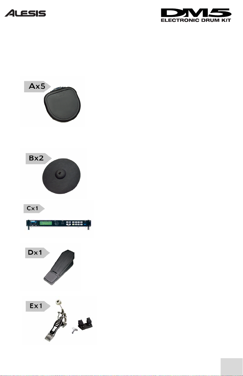
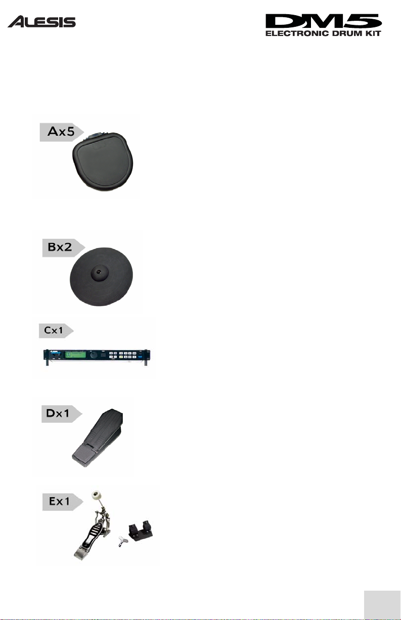
A. Pads (5 total)
These pads are used to trigger sounds from the DM5
module. There are 5 pads included in the kit (1 for the
kick drum, 1 for snare, 1 hi-hat, and 2 toms). These
pads are identical and can be configured in any way that
suits the needs of the drummer. For example, if a
drummer needs 3 toms and no snare, this can be
arranged through the DM5 module.
B. Cymbals (2 total)
The DM5 drum kit includes two cymbals intended for
use as ride and crash cymbals. Like the pads listed
above, these cymbals are interchangeable and can be
configured in any way that suits the drummer.
3
C. DM5 Drum Module
This is the “brain” of your electronic drum kit. All of
your pads connect to this module, and sounds are
generated within this unit. The unit includes a
mounting kit that allows for convenient placement near
the drummer, but the unit can also be rack mounted.
D. Hi-hat Pedal
This pedal is used to open and close your electronic hihat. The throw of the pedal is adjustable, as described
later in this manual.
E. Kick Pedal
This kick drum pedal feels and works just like an
acoustic kick drum pedal. The included clamping
mechanism (shown to the right of the pedal) is used to
attach the pedal to the rack in order to keep the pedal
from moving around during performance.

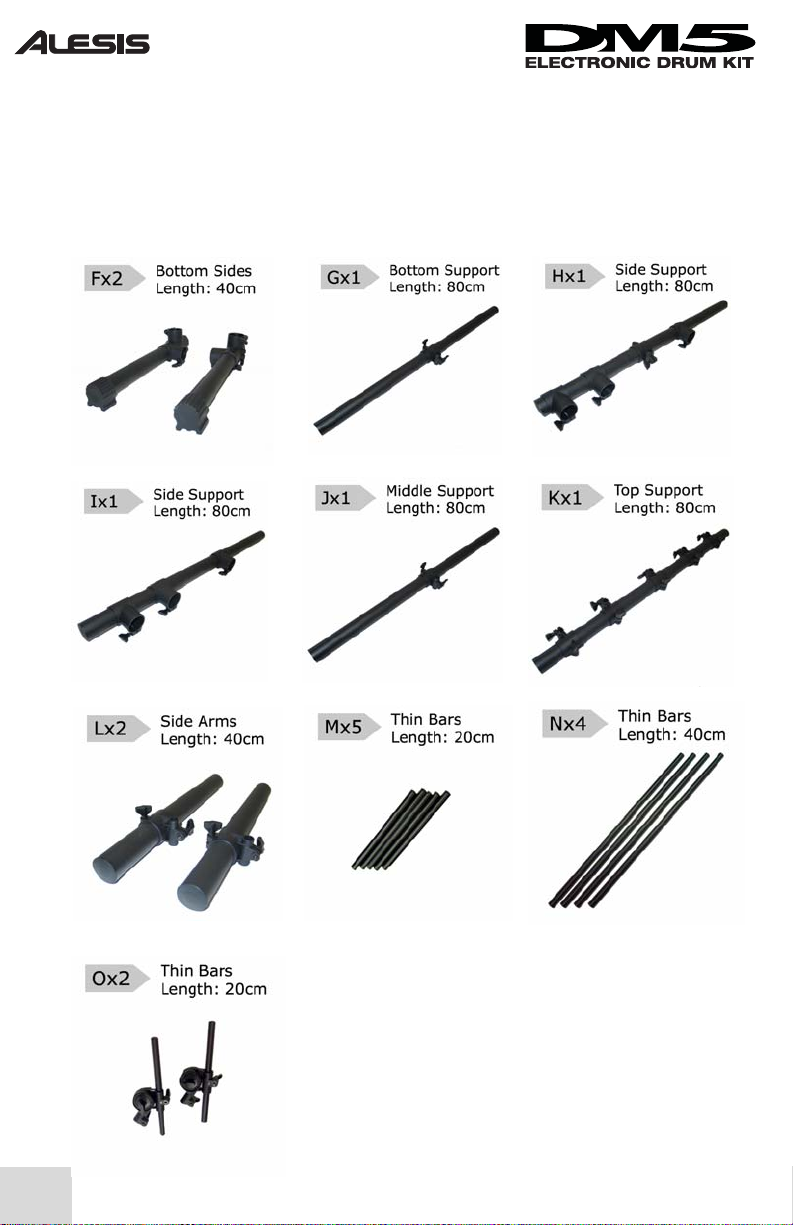
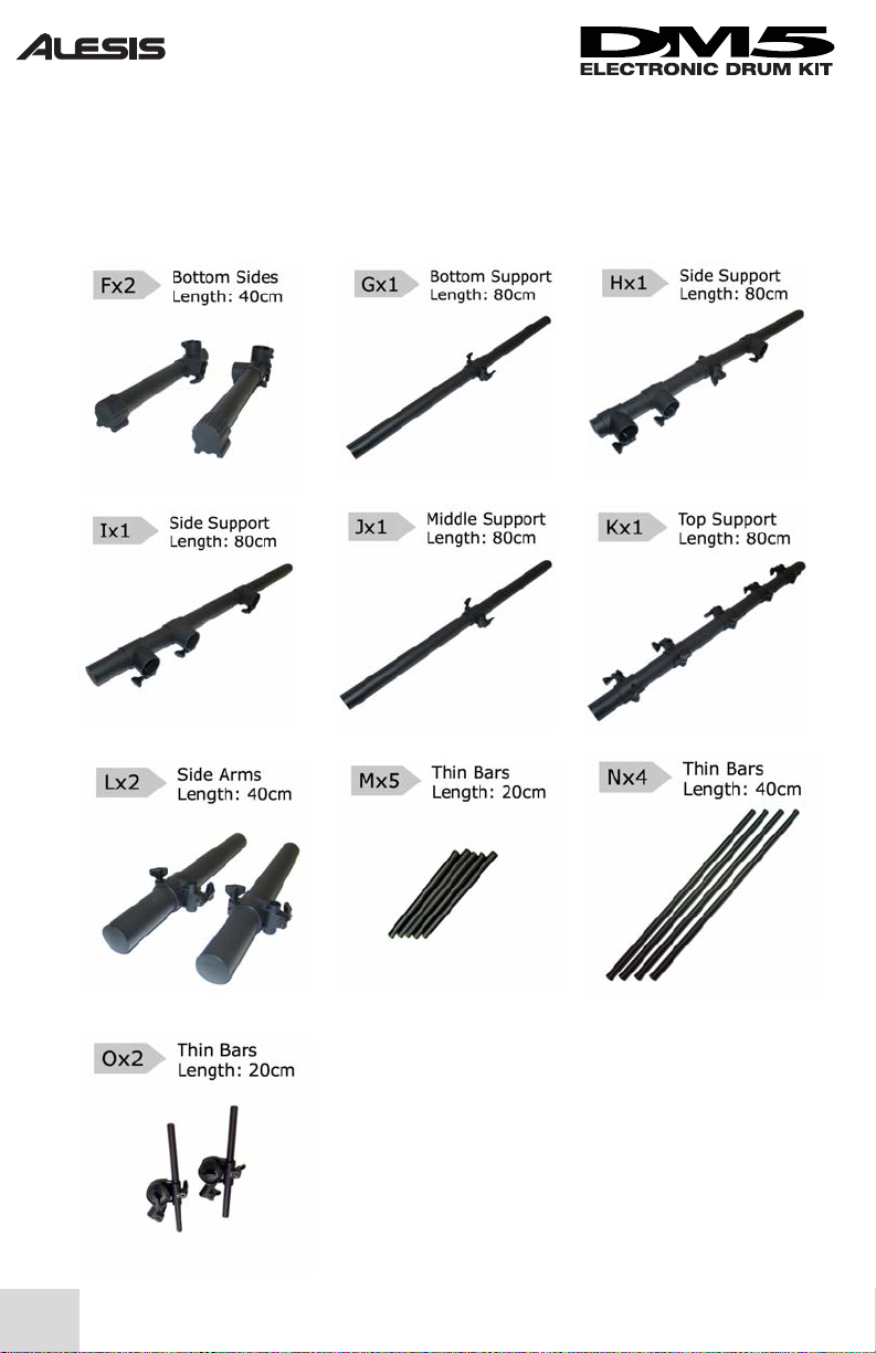
Your DM5 Drum Kit should also include the following pieces in order to assemble the drum
rack. Like the main components of the drum kit, each part of the rack is assigned a letter.
The diameter and length is listed next to each piece. The rack includes the following:
4

Putting It All Together
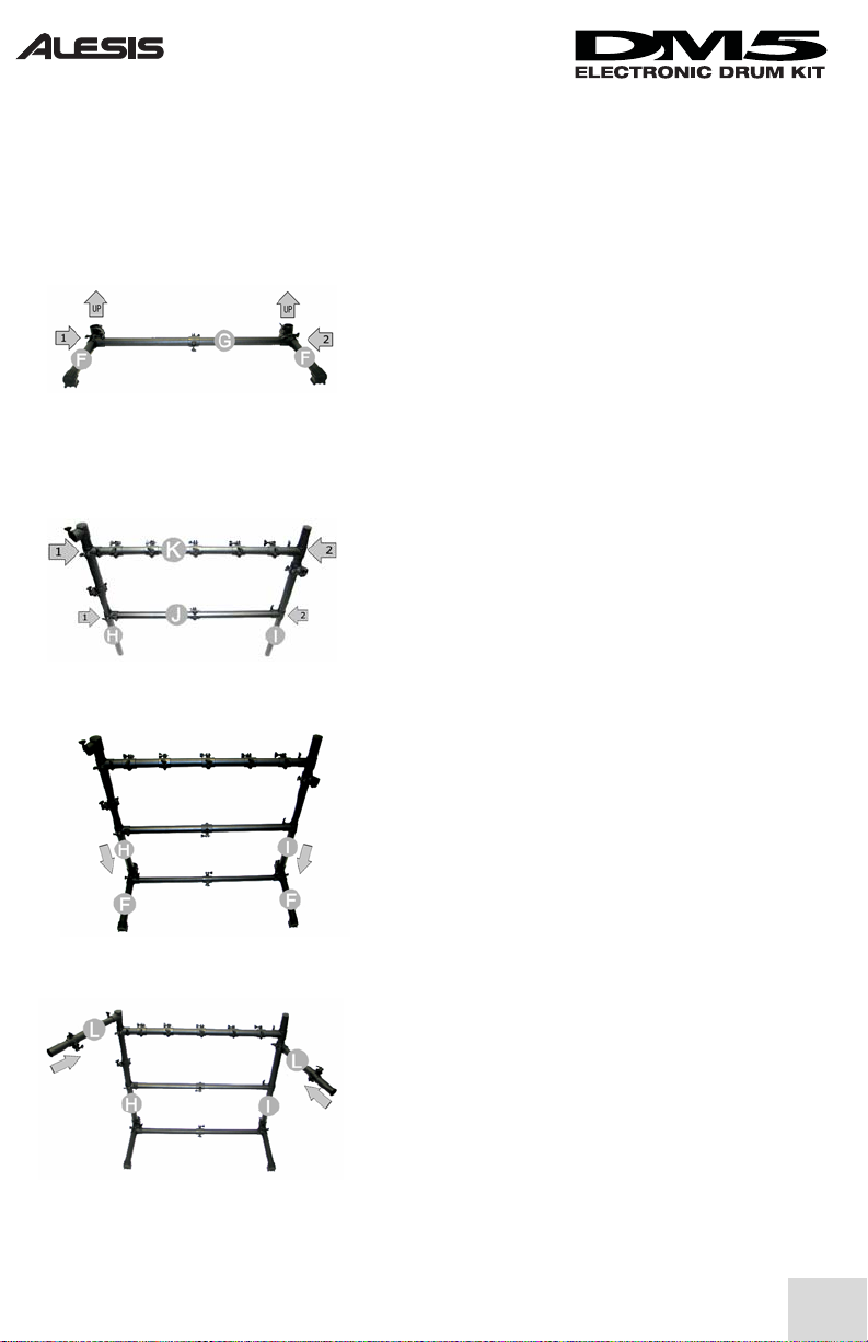
Step 1: Building the base
Lay the rack’s “G” section on the ground and connect
the two “F” sections as shown in the picture. Each
“F” section should have an open socket that faces up.
Tighten all thumb screws to be finger-tight.
Step 2: Building the rack
First, connect the “J” and “K” cross sections to the
“H” side section. Now connect the other ends of “J”
and “K” to the “I” section. Tighten all thumb screws
to be finger tight.
The “H” bar on the left should have two connectors
free and the “I” section on the right should have one
connector free. Also, the endcaps on sections “H” and
“I” should be facing upwards.
5
Step 3: Connecting the rack to the base
Now connect the main rack assembled in step 2 to the
base assembled in step 1. There are two open
connectors facing up on the base. The bottom of
sections “H” and “I” on the rack should fit nicely into
the two connectors on the base.
.=
Step 4: Attaching the arms
Attach the two arms as illustrated in the diagram to the
left. Both arms are identical. The arm on the left
attaches to the open connector at the top of section
“H”. The arm on the right attaches to the open
connector on section “I”. Make sure that the endcaps
of both arms are facing outward.

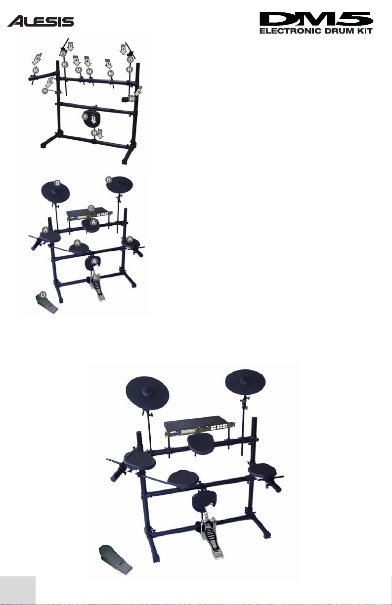
Step 5: Attaching the extension poles
Now we need to add the “M,” “N,” and “O” extension
poles to the appropriate mounting points on the rack.
The locations of these poles are shown in the picture to
the left.
Step 6: Attaching the rest of the hardware
Finally, add the drum hardware (pads, pedals, cymbals,
and DM5 module) to the rack. You can mount the
DM5 module either above the main pole (as shown) or
below the main pole. Connect the kick drum pedal to
the bottom pole.
6
Your DM5 Drum Kit is now assembled and should look like the one below. At this point
you can adjust the height and position of the various components to suit your playing style.
If you wish, you can even re-arrange the drum pads differently from what is shown below.

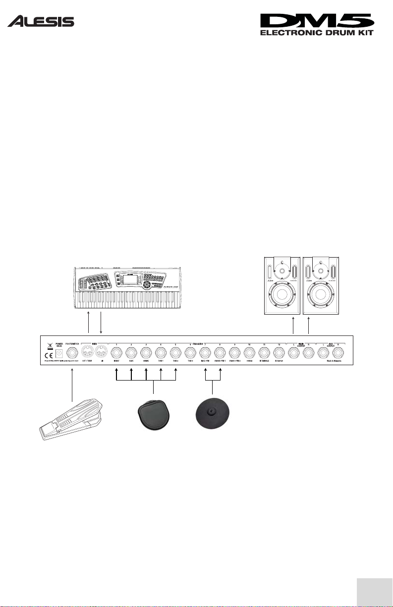
Hooking Everything Up
The pads, cymbals, and hi-hat pedal each have a 1/8” plug that connects to the ¼” jacks on
the rear of the DM5 module. The inputs on the rear of the DM5 module are labeled (hi hat,
kick, snare, etc.) Connect each pad to its corresponding input. If you have additional drum
pads or cymbals you’d like to use, feel free to connect them to the remaining 5 inputs on the
DM5 module.
If you’re using headphones to monitor the drums, you can plug them into the “phones” jack
on the front of the DM5 module. If you’re not using headphones, you’ll need some speakers
to hear the output of the DM5 module. The speakers can be hooked up to the “Main
Output” jacks on the module.
If you have a MIDI keyboard, sound module, or MIDI sequencing computer, you can hook
it up to the DM5 module using standard 5-pin MIDI cables.
Finally, use the included Velcro straps to neatly fasten all cables to the poles.
7
Refer to the DM5’s reference manual for how to configure the module itself.

Adjusting the Hi-Hat Pedal
The DM5 Drum Kit’s hi-hat pedal can be adjusted to give you varying amounts of tension.
This is done through a small screw found on the bottom of the pedal. Use a Phillips-head
screwdriver to adjust the tension on the pedal.
Turning the screw clockwise will make the pedal stiffer whereas turning counterclockwise
will loosen the pedal.
8
Expanding Your Kit
Extra pads and cymbals are sold separately. See your authorized Alesis dealer for details.
For Further Assistance
See the Safety/Warranty booklet for Alesis contact information. In the U.S., call the Alesis
service phone number for spare parts, missing parts, or for answers to any questions you
may have.

Manual de inicio rápido del usuario (Español)
9

Instalación rápida del kit de batería electrónica DM5
y Asegúrese de que todos los artículos enumerados en la cubierta frontal estén
incluidos en la caja del kit de batería electrónica DM5.
y Lea las instrucciones de seguridad importantes incluidas en la caja.
y Estudie los diagramas de montaje y conexión de más abajo.
y Una vez que esté todo enchufado, encienda todo. Si conectó el módulo DM5 a
un sistema de amplificación para altavoces, asegúrese de encender los altavoces
en último término para evitar que el estampido de encendido los dañe.
y Lea el manual de referencia del DM5 y experimente con sus diversos parámetros.
y Cuando termine, apague los altavoces y el sistema de amplificación de los mismos
antes de apagar el módulo DM5.
y Vaya a www.alesis.com y registre su kit de batería DM5.
10

Componentes del kit de batería electrónica DM5
Antes de comenzar el montaje de su kit de batería DM5, asegúrese de que la caja contenga
todas las piezas necesarias. Cada pieza de la batería tiene asignada una letra. La caja debe
contener lo siguiente.
A. Pads (5 en total)
Estos pads se usan para disparar sonidos del módulo
DM5. El kit incluye 5 pads (1 para kick (bombo), 1
para snare (redoblante), 1 hi-hat y 2 toms). Estos
pads son idénticos y se pueden configurar de
cualquier manera que se adecue a las necesidades del
baterista. Por ejemplo, si el baterista necesita 3 toms
y ningún snare, es posible lograr esta disposición
mediante el módulo DM5.
B. Platillos (2 en total)
El kit de batería DM5 incluye dos platillos para usar
como platillos ride y crash. Como los pads arriba
indicados, estos platillos son intercambiables y se
pueden configurar de cualquier manera que se adecue
al baterista.
C. Módulo de batería DM5
11
Este módulo es el “cerebro” del kit de batería
electrónica. Todos los pads se conectan a este
módulo, que genera los sonidos. La unidad incluye
un kit de montaje que permite la ubicación
conveniente cerca del baterista, pero también se
puede montar en un bastidor (rack).
D. Pedal de hi-hat
Este pedal se usa para abrir y cerrar el hi-hat
electrónico. La tensión (dureza) del pedal es
ajustable, como se explica más adelante.
E. Pedal de kick
El pedal de kick se siente y funciona como un pedal
de kick acústico. El mecanismo de sujeción incluido
(ilustrado a la derecha del pedal) se usa para fijarlo al
bastidor a fin de evitar que se desplace durante la
ejecución.

El kit de batería DM5 incluye también las siguientes piezas necesarias para el montaje en
el bastidor. Al igual que los componentes principales del kit de batería, cada pieza del
bastidor tiene asignada una letra. El diámetro y la longitud se indican junto a cada pieza.
El bastidor incluye lo siguiente:
12

Montaje del conjunto
Paso 1: Construcción de la base
Coloque la sección “G” del bastidor en el piso y
conecte las dos secciones “F” como se ilustra en la
imagen. Cada sección “F” debe tener un zócalo
abierto que mira hacia arriba. Apriete todos los
tornillos con la mano.
Paso 2: Construcción del bastidor
Conecte primero las secciones transversales “J” y
“K” a la sección lateral “H”. A continuación, conecte
los otros extremos de “J” y “K” a la sección “I”.
Apriete todos los tornillos con la mano.
La barra “H” de la izquierda debe tener dos
conectores libres y la sección “I” de la derecha uno.
Asimismo, los capuchones de extremo de las
secciones “H” e “I” deben mirar hacia arriba.
13
Paso 3: Conexión del bastidor a la base
Conecte ahora el bastidor principal armado en el paso
2 a la base armada en el paso 1. En la base hay dos
conectores abiertos que miran hacia arriba. La parte
inferior de las secciones “H” e “I” del bastidor debe
encajar fácilmente en los dos conectores de la base.
.=
Paso 4: Fijación de los brazos
Fije los dos brazos como se ilustra en el diagrama de
la izquierda. Ambos brazos son idénticos. El de la
izquierda se fija al conector abierto de la parte
superior de la sección “H”. El de la derecha se fija al
conector abierto de la sección “I”. Asegúrese de que
los capuchos de extremo de ambos brazos queden
mirando hacia afuera.

Paso 5: Fijación de los postes de extensión
Ahora es necesario agregar los postes de extensión
“M”, “N” y “O” a los puntos de montaje apropiados
del bastidor.
Las posiciones de estos postes se ilustran en la
imagen de la izquierda.
Paso 6: Fijación del resto de los elementos
Finalmente, agregue al bastidor los elementos de la
batería (pads, platillos y módulo DM5). Es posible
montar el módulo DM5 ya sea sobre el poste
principal (como se muestra) como debajo del mismo.
Conecte el pedal del kick al poste inferior.
De esta manera, el kit de batería DM5 queda armado y debe tener el aspecto abajo
ilustrado. En este momento, es posible ajustar la altura y posición de los diversos
componentes para adecuarlos a su estilo de ejecución. Si lo desea, puede incluso
disponer los pads de la batería en forma diferente de la que se ilustra abajo.
14

Conexión de los elementos
Los pads, los platillos y el pedal de hi-hat tienen cada uno un enchufe de 1/8" que se
conecta a los jacks de 1/4" de la parte trasera del módulo DM5. Las entradas de la parte
trasera del módulo están rotuladas (hi hat, kick, snare, etc.) Conecte cada pad a la
entrada correspondiente. Si tiene pads de tambores o platillos adicionales que le gustaría
usar, puede conectarlos libremente a las 5 entradas restantes del módulo DM5.
Si usa auriculares para monitorear la batería, puede conectarlos al jack fonográfico
“Phones” del frente del módulo. Si no los usa, necesitará altavoces para oír la salida del
DM5. Dichos altavoces se pueden conectar a los jacks “Main Output” (Salida principal)
del módulo.
Si tiene un teclado MIDI, un módulo de sonido o una computadora de secuencia MIDI,
puede conectarlo al módulo DM5 con cables MIDI estándar de 5 pines.
Finalmente, use las tiras de Velcro incluidas para sujetar prolijamente todos los cables a los
postes.
15
Para saber cómo configurar el módulo propiamente dicho, consulte el manual de referencia
del DM5.

Ajuste del pedal de hi-hat
El pedal de hi-hat del kit de batería DM5 se puede ajustar para darle valores de tensión
variables. Esto se hace mediante un pequeño tornillo que se encuentra en la parte inferior
del pedal. Use un destornillador Phillips para ajustar la tensión.
Si se gira el tornillo en sentido horario, el pedal se pone más duro, mientras que si se gira a la
izquierda, el pedal se afloja.
Se venden pads y platillos adicionales por separado. Consulte los detalles a su
distribuidor Alesis autorizado.
Consulte la información de contacto de Alesis en el folleto de Seguridad/Garantía.
16
Cómo ampliar el kit
Para lograr asistencia adicional

Guide d’utilisation simplifié (Français)
17

Guide d'installation rapide pour l’ensemble de
batterie électronique DM5
y Assurez-vous que tous les articles énumérés sur la page couverture de ce guide
sont inclus dans la boîte de l'ensemble de batterie électronique DM5.
y Veuillez lire les consignes de sécurité fournies dans la boîte.
y Examinez le schéma d’assemblage et d’installation ci-dessus.
y Une fois que tout est branché, mettez tous les appareils sous tension. Si vous
avez branché le module DM5 à un système de sonorisation, assurez-vous de
mettre les enceintes acoustiques sous tension en dernier pour éviter
d’endommager les haut-parleurs.
y Lisez le guide de référence du DM5 et amusez-vous à expérimenter avec ses
nombreux paramètres.
y Lorsque vous avez terminé, fermez toujours les enceintes acoustiques et le
système de sonorisation avant de mettre le module DM5 hors tension.
y Visitez le www.alesis.com pour enregistrer votre ensemble de batterie électrique
DM5.
18
Éléments de l'ensemble de batterie électronique DM5
Avant de commencer l'assemblage, assurez-vous que tous les articles dont vous avez besoin
sont inclus dans la boîte. Chaque pièce de l’ensemble de batterie est identifiée par une lettre,
voici ce que vous devriez avoir :
A. Pads (5 au total)
Ces pads sont utilisés pour déclencher des sons du
module DM5. Il y a 5 pads d’inclus dans l'ensemble (1
pour la grosse caisse, 1 pour la caisse claire, 1 pour le
charleston et 2 pour les toms). Ces pads sont
identiques et peuvent être configurés de plusieurs
façons pour accommoder le batteur. Par exemple, si
un batteur a besoin de 3 toms, mais pas de caisse claire,
il peut configurer le module DM5 pour répondre à ses
besoins.
B. Cymbales (2 au total)
L'ensemble DM5 comprend deux cymbales pour servir
de cymbale ride et crash. Tout comme les pads décrits
ci-dessus, ces cymbales sont interchangeables et
peuvent être configurées selon les besoins du batteur.
19
C. Module de batterie DM5
Cet élément est le « cerveau » de l'ensemble de batterie.
Tous les pads se branchent à ce module et les sons sont
générés par ce dispositif. Ce dispositif est doté d’un
support qui permet de le placer près du batteur, mais il
peut également être monté sur le bâti.
D. Pédale de charleston
Cette pédale sert à ouvrir et à fermer la cymbale
charleston électronique. La force de poussée est
ajustable, tel qu’il est décrit plus loin dans ce guide.
E. La pédale pour la grosse caisse
La pédale de la grosse caisse offre la même sensation et
fonctionne de la même façon qu’une pédale de grosse
caisse acoustique. Le mécanisme de serrage (montré à
la droite de la pédale) est utilisé pour fixer la pédale au
bâti pour l’empêcher de se déplacer durant la
performance.
L’ensemble de batterie DM5 comprend également les éléments suivants pour l’assemblage
du bâti. Tout comme les éléments principaux de l’ensemble, chaque pièce est identifiée par
une lettre. Le diamètre et la longueur sont indiqués à côté de chaque pièce. Le bâti
comprend les pièces suivantes :
20
L'assemblage
Étape 1 : Montage de la base
Déposez la section « G » du bâti sur le plancher et
raccordez les deux sections « F » tel qu’indiqué dans
l’image. Chaque section « F » doit avoir une emboîture
vers le haut. Serrez toutes les vis à serrage à main.
Étape 2 : Montage du bâti
Commencez par raccorder les sections transversales
« J » et « K » à la section latérale « H ». Raccordez
maintenant les deux bouts de « J » et « K » à la section «
I ». Serrez toutes les vis à serrage à main.
La barre « H » sur la gauche doit avoir deux raccords de
libres et la section « I » à la droite doit avoir un raccord
de libre. En plus, les embouts des sections « H » et
« I » doivent faire face vers le haut.
21
Étape 3 : Raccorder le bâti à la base
Raccordez maintenant le bâti assemblé dans l’étape 2 à
la base assemblée dans l’étape 1. Sur la base, il y a deux
raccords avec l’emboîture vers le haut. Le dessous des
sections « H » et « I » sur le bâti doit bien s’insérer dans
les deux raccords de la base.
.=
Étape 4 : Raccorder les bras
Fixez les deux bras tel qu’indiqué sur le diagramme de
gauche. Les deux bras sont identiques. Le bras de
gauche se fixe à l’emboîture sur le dessus de la section
« H ». Le bras de droite se fixe à l’emboîture sur la
section « I ». Assurez-vous que les embouts des deux
bras soient placés vers l’extérieur.
Étape 5 : Raccorder les barres d’extension
Nous devons maintenant placer les barres d’extension
« M », « N » et « O » aux bons endroits sur le bâti.
Les emplacements pour ces barres sont indiqués sur
l’image de gauche.
Étape 6 : Raccorder le reste de la quincaillerie
Finalement, ajoutez la quincaillerie de batterie (pads,
pédales, cymbales et module DM5) sur le bâti. Vous
pouvez fixer le module DM5 au-dessus de la barre
principale (tel qu’indiqué) ou sous la barre principale.
Raccordez la pédale de la grosse caisse sur la barre du
bas.
Votre ensemble de batterie électronique DM5 est maintenant assemblé et devrait ressembler
à celui ci-dessous. Vous pouvez maintenant ajuster la hauteur et la position des différents
éléments pour répondre à vos besoins. Vous pouvez également repositionner les pads
différemment de l'image ci-dessous.
22
Branchement
Les pads, les cymbales et le charleston ont chacun une prise de 1/8 po qui se branche aux
entrées de ¼ po à l’arrière du module DM5. Les entrées à l’arrière du module DM5 sont
identifiées (charleston, grosse caisse, caisse claire, etc.). Branchez chaque pad à l’entrée
correspondante. Si vous avez des pads de batterie ou des cymbales supplémentaires que
vous désirez utiliser, vous pouvez les brancher aux 5 entrées restantes du module DM5.
Si vous utilisez un casque d'écoute, vous pouvez le brancher dans l'entrée « PHONES » sur
le devant du module DM5. Si vous n’utilisez pas de casque d’écoute, vous aurez besoin
d’enceintes acoustiques pour entendre le signal de sortie du module DM5. Les enceintes
peuvent être branchées aux entrées « MAIN OUTPUT » du module.
Si vous avez un clavier MIDI, module de son, ou un séquenceur MIDI, vous pouvez le
brancher au module DM5 à l’aide de câble MIDI à cinq broches de raccordement standard.
Puis, utilisez les bandes velcro pour attacher tous les câbles aux barres.
23
Veuillez consulter le guide de référence pour savoir comment procéder à la configuration du
Module DM5.

Ajustement de la pédale charleston
La pédale charleston de l’ensemble de batterie électronique DM5 peut être ajustée à
différente tension. Vous pouvez faire l'ajustement à l’aide d’une petite vis sous la pédale. À
l’aide d’un tournevis cruciforme, réglez la résistance de la pédale.
Pour augmenter la résistance de la pédale, tourner la vis dans le sens horaire, pour la
diminuer, tourner dans le sens antihoraire.
Il est possible d'acheter des pads et des cymbales supplémentaires. Communiquez avec un
détaillant autorisé Alesis pour de plus amples détails.
Vous trouverez les coordonnées pour communiquer avec Alesis dans le livret intitulé
Sécurité/Garantie.
24
Ajouter des éléments à votre ensemble
Pour de plus amples renseignements

Kurzbedienungsanleitung (Deutsch)
25

Aufbauanleitung des DM5 Electronic Drum Kit
y Überprüfen Sie, dass alle auf der Vorderseite abgebildeten Gegenstände in der
Verpackung des DM5 Drum Kits enthalten sind.
y Lesen Sie die der Verpackung beiliegenden „Wichtigen Sicherheitshinweise.“
y Sehen Sie sich die Aufbau- und Anschlussabbildungen auf den folgenden Seiten
dieser Anleitung an.
y Wenn alles angeschlossen ist, schalten Sie alle Geräte ein. Schalten Sie die
Lautsprecher zuletzt ein, wenn Ihr DM5 Modul mit einem PA System verbunden
ist, um Beschädigungen der Lautsprecher durch Einschaltgeräusche vorzubeugen.
y Lesen Sie das Bedienungshandbuch des DM5 und probieren Sie die
verschiedenen Parameter aus.
y Nach dem Spielen, schalten Sie erst die Lautsprecher und das PA-System aus,
bevor Sie das DM5 Modul ausschalten.
y Registrieren Sie Ihr DM5 Drum Kit auf www.alesis.de.
26

Bestandteile des DM5 Electronic Drum Kit
Vergewissern Sie sich, dass im Karton alle benötigten Teile enthalten sind, bevor Sie
beginnen, das DM5 Drum Kit zusammenzubauen. Jedes Teil des Drum Kits trägt einen
Buchstaben. Folgende Bestandteile sollten Sie haben:
A. Pads (insgesamt 5)
Diese Pads werden zum Triggern von Sounds des DM5
Moduls verwendet. Dem Kit liegen 5 Pads bei (1 Kick
Drum-, 1 Snare-, 1 Hi-Hat- und 2 Tom Pads). Diese
Pads sind identisch und können nach Ihrem
persönlichen Geschmack konfiguriert werden. Ein
Drummer benötigt beispielsweise 3 Tom Pads und
keine Snare – mit dem DM5 Modul kein Problem.
B. Becken (insgesamt 2)
Das DM5 Drum Kit enthält zwei Becken Pads, die als
Ride- und Crash Becken gedacht sind. Wie schon bei
den oberen Pads angemerkt, können auch diese Pads
dem persönlichen Geschmack des Drummers
angepasst werden.
27
C. DM5 Drum Modul
Das ist das „Gehirn” Ihres elektronischen Drum Kits.
Alle Pads sind mit diesem Modul verbunden und die
eigentlichen Klänge werden vom DM5 erzeugt. Das
Gerät ist für den Rackeinbau vorgesehen oder kann mit
einem Montagekit, welches eine Platzierung beim
Drummer ermöglicht, betrieben werden.
D. Hi-Hat Pedal
Dieses Pedal wird zum Öffnen und Schließen Ihrer
elektronischen Hi-Hat verwendet. Wir erklären später
in der Anleitung die Handhabung des Pedals.
E. Kick Pedal
Das Kick Pedal funktioniert genau wie ein Kick Pedal
für ein akustisches Drumset. Der KlammerMechanismus (rechts im Bild) ermöglicht eine
Pedalbefestigung ans Rack, damit das Pedal beim
Spielen nicht verrutschen kann.

g
g
g
g
g
g
g
g
g
g
Ihr DM5 Drum Kit sollte des Weiteren die folgenden Teile zum Zusammenbau des Drum
Racks besitzen. Wie auch die anderen Kit-Bestandteile, ist jedes Teil mit einem Buchstaben
markiert. Der Durchmesser und die Länge stehen neben jedem Teil. Zum Rack gehören:
Fußseiten
e: 40cm
Län
Fußhalter
e: 80cm
Län
Seitenstütze
e: 80cm
Län
Seitenstütze
e: 80cm
Län
Mittelstütze
e: 80cm
Län
Obere Stütze
e: 80cm
Län
Seitenarme
e: 40cm
Län
Haltestangen
e: 20cm
Län
Haltestangen
e: 40cm
Län
28
Beckenhalter
e: 20cm
Län

Aufbauanleitung
Schritt 1: Der Fuß
Legen Sie das „G” Stück auf den Boden und befestigen
Sie die beiden „F” Teile, wie abgebildet. Jedes „F”
Stück sollte ein Verbindungsnut haben, das nach oben
sehen sollte. Ziehen Sie alle Schrauben handfest an.
Schritt 2: Aufbau des Racks
Verbinden Sie erst die „J” und „K” Teile mit den „H”
Seiten. Bringen Sie nun der anderen Seite der „J” und
„K” Teile die „I” Stütze an. Ziehen Sie alle Schrauben
handfest an.
An der „H” Stütze links sollten zwei
Verbindungsflansche und am „I” Stück rechts eine
Verbindungsnut frei sein. Die Endkappen der Teile
„H” und „I” sollten nach oben gerichtet sein.
29
Schritt 3: Verbindung des Fußes mit dem Rack
Stecken Sie nun das in Schritt 2 zusammengefügte
Main Rack in den Fuß (siehe Schritt 1). Am Fuß
befinden sich zwei nach oben schauende Flansche. Die
Enden der „H” und „I” Teile des Racks sollten in diese
zwei Flansche hineinpassen.
.=
Schritt 4: Seitenarme befestigen
Befestigen Sie gemäß der Abbildung die beiden
Seitenarme. Beide Arme sind identisch. Der linke Arm
wird an den freien Flansch an der Spitze der „H”
Stütze angebracht. Der rechte Arm wird an den freien
Flansch der „I” Stütze befestigt. Vergewissern Sie sich,
dass die Endkappen beider Arme nach außen zeigen.

Schritt 5: Montage der Haltestangen
Nun müssen Sie die „M,” „N” und „O” Haltestangen
an den vorgesehenen Montagehalterungen des Racks
anbringen.
Die Positionen dieser Halterungen werden in der linken
Abbildung gezeigt.
Schritt 6: Anschluss der übrigen Hardware
Zuletzt können Sie die Drum Hardware (Pads, Pedale,
Becken und das DM5 Modul) am Rack befestigen. Sie
können das DM5 Modul entweder wie gezeigt über
oder unter der Stütze befestigen. Befestigen Sie das
Kick Drum Pedal mit dem Fuß.
Ihr DM5 Drum Kit ist nun fertig aufgebaut und sollte wie im Bild unten aussehen. Nun
haben Sie die Möglichkeit, die Höhe und die Position der verschiedenen Komponenten auf
Ihren Drumstil anzupassen. Falls nötig können Sie die Drum Pads auch umplatzieren.
30

Alles anschließen
Jedes Pad, die Becken und das Hi-Hat Pedal besitzt einen 3,5mm Klinkenstecker, der an den
rückseitigen 3,5mm Klinkenbuchsen des DM5 Moduls angeschlossen wird. Die Eingänge
des DM5 Moduls sind gekennzeichnet (Hi Hat, Kick, Snare, usw.) Verbinden Sie jedes Pad
mit dem jeweiligen Eingang. Wenn Sie zusätzliche Drum- oder Becken Pads verwenden
wollen, können Sie diese an den verbleibenden 5 Eingängen des DM5 Moduls anschließen.
Wenn Sie beim Spielen Kopfhörer verwenden wollen, schließen Sie diese an die „Phones”
Buchse an der Vorderseite des DM5 Moduls an. Wenn Sie keine Kopfhörer haben, brauchen
Sie Lautsprecher, um den Drumsound des DM5 hören zu können. Lautsprecher schließen
Sie an den „Main Output” Buchsen des Moduls an.
Wenn Sie ein MIDI Keyboard, Sound Modul oder einen MIDI Sequencer verwenden wollen,
verbinden Sie das DM5 Modul mit Hilfe Standard 5-Pin MIDI-Kabeln mit den Geräten.
Verwenden Sie zum Schluss die beiliegenden Kabelbinder, um alle Kabel am Rack
festzuziehen.
31
Zur Konfiguration des Moduls beachten Sie bitte die Bedienungsanleitung des DM5.

Das Hi-Hat Pedal einstellen
Das Hi-Hat Pedal des DM5 Drum Kits kann mit Hilfe einer kleinen Schraube an der
Unterseite des Pedals auf verschiedene Zugstärken eingestellt werden. Mit einem
Kreuzschraubenzieher können Sie die Zugstärke einstellen.
Wenn Sie die Schraube in Uhrzeigerrichtung drehen, wird die Federspannung fester. In
umgekehrten Uhrzeigersinn ist die Spannung leichter.
Zusätzliche Pads und Becken erhalten Sie separat bei einem Alesis Händler.
Gehen Sie auf die Kontaktseite unserer Webseite www.alesis.de. Rufen Sie aus Deutschland
oder Österreich die Telefonnummer des Alesis Customer Support Büros an, wenn Teile
fehlen oder Sie ein Ersatzteil benötigen. Wir beantworten auch gern weitere Fragen rund um
Alesis und Ihr Produkt.
32
Erweitern Sie Ihr Kit
Weitere Hilfestellungen

Manuale rapido di utilizzazione (Italiano)
33

Impostazione rapida del Kit batteria elettronica DM5
y Verificare che tutti gli elementi elencati sul frontespizio di questa guida siano
inclusi nella confezione del Kit batteria DM5.
y Leggere il libretto delle istruzioni di sicurezza incluso nella confezione.
y Esaminare attentamente gli schemi di montaggio e di collegamento sottostanti.
y Una volta collegato tutto, accendere tutti i dispositivi. Nel caso in cui si abbia
collegato il modulo DM5 ad un sistema PA, assicurarsi di accendere gli
altoparlanti per ultimi per evitare che eventuali “tonfis” danneggino gli
altoparlanti.
y Leggere il manuale di riferimento del DM5 e provare i vari parametri.
y Una volta terminato, spegnere gli altoparlanti e il sistema PA prima di spegnere il
modulo DM5.
y Recarsi sul sito www.alesis.com per la registrazione del Kit batteria DM5.
34
Componenti del Kit batteria elettronica DM5
Prima di iniziare a montare il Kit batteria DM5, assicurarsi che la confezione contenga tutti i
pezzi necessari. Ad ogni pezzo corrisponde una lettera e dovreste essere in possesso di:
A. Pad (5 in tutto)
Questi pad servono per generare suoni dal modulo
DM5. Il kit comprende 5 pad (1 kick, 1 rullante, 1 hihat, e 2 tom). Questi pad sono identici e possono
essere configurati in qualsiasi modo soddisfi il batterista.
Ad esempio, se il batterista ha bisogno di 3 tom e di
nessun rullante, ciò può essere sistemato tramite il
modulo DM5.
B. Piatti (2 in tutto)
Il kit batteria DM5 comprende 2 piatti da usare come
piatti ride e crash. Come nel caso dei pad, i piatti sono
interscambiabili e possono essere configurati come
meglio aggrada al batterista.
C. Modulo batteria DM5
35
Questo è il “cervello” del vostro kit batteria elettronica.
Tutti i pad sono collegati a questo modulo e i suoni
sono generati da questo dispositivo. L’apparecchio
include un kit di montaggio che consente di
posizionarlo adeguatamente vicino al batterista, ma può
essere anche montato su rack.
D. Pedale Hi-hat
Questo pedale serve per aprire e chiudere il hi-hat
elettronico. La gittata del pedale è regolabile, come
descritto in seguito in questo stesso manuale.
E. Pedale Kick
Questo pedale kick percepisce e lavora esattamente
come un pedale acustico per batteria. Il meccanismo di
fissaggio accluso (mostrato alla destra del pedale) serve
per fissare il pedale stesso al rack per impedire al pedale
di spostarsi durante l'esibizione.
Il Drum Kit DM5 include inoltre i seguenti pezzi per il montaggio del rack della batteria.
Come i componenti principali del drum kit, ogni elemento è contrassegnato da una lettera. Il
diametro e la lunghezza sono elencati vicino ad ogni pezzo. Il rack include:
36

Montare il tutto
Fase 1: montaggio della base
Appoggiare a terra la sezione “G” del rack e collegare le
due sezioni “F” come illustrato. Ogni sezione “F” deve
presentare un supporto rivolto verso l’alto. Stringere
tutte le viti ad alette.
Fase 2: montaggio del supporto
Per prima cosa, collegare le sezioni trasversali “J” e “K”
alla sezione laterale “H”. Ora collegare gli altri capi di
“J” e “K” alla sezione “I”. Stringere tutte le viti ad
alette.
La barra “H” a sinistra deve presentare due connettori
liberi e la sezione “I” a destra deve averne uno. Inoltre,
le parti terminali delle sezioni “H” ed “I” devono
essere rivolte verso l’alto
37
Fase 3: collegamento del supporto con la base
Collegare ora il rack principale montato nella fase 2
allabase assemblata nella fase 1. Sulla base vi sono due
connettori aperti rivolti verso l’alto. La parte inferiore
delle sezioni “H” ed “I” sul rack dovrebbero adattarsi
perfettamente ai due connettori sulla base.
.=
Fase 4: collegamento dei bracci
Collegare i due bracci come illustrato nel diagramma a
sinistra. I bracci sono identici. Il braccio di sinistra si
fissa al collettore aperto in cima alla sezione “H”. Il
braccio di detra si fissa al collettore aperto sulla sezione
“I”. Assicurarsi che le parti terminali dei due bracci
siano rivolte verso l’esterno.

Fase 5: montaggio delle aste di estensione
Ora bisogna montare gli assi di estensione “M,” “N,”
ed “O” ai giusti punti di montaggio sul rack.
Le disposizioni di questi assi sono mostrate
nell’immagine a sinistra.
Fase 6: montaggio del resto dell’hardware
Infine, aggiungere l’hardware della batteria (pad, pedali,
piatti e il modulo DM5) al rack. Il modulo DM5 può
essere montato o sull’asse principale (come illustrato) o
sotto di esso. Collegare il pedale del kick all’asse
inferiore.
Il vostro Kit batteria DM5 è ora montato e deve apparire come quello sottostante. A questo
punto si può regolare l’altezza e la posizione dei vari elementi per adeguarla al vostro stile.
Volendo, è possibile disporre i pad in modo diverso da quanto illustrato.
38

Collegamento del tutto
I pad, i piatti e il pedale hi-hat sono dotati di una spina da 1/8” che si collega ai jack da ¼”
posti sul retro del modulo DM5. Gli ingressi posti sul retro del modulo DM5 sono etichettati
(hi hat, kick, snare, ecc.). Collegare ogni pad all’ingresso corrispondente. Se si possiedono
pad o piatti aggiuntivi che si desidera utilizzare, collegarli ai rimanenti 5 ingressi del modulo
DM5.
Nel caso in cui vi serviate di cuffie per monitorare la batteria, è possibile inserirle nel jack
“cuffie” posto sulla parte anteriore del modulo DM5. Se non si usano cuffie saranno
necessari altoparlanti per ascoltare l’uscita del modulo DM5. Gli altoparlanti possono essere
collegati ai jack di uscita principale “Main Output” del moduo.
Nel caso possediate una tastiera MIDI, un modulo sonoro o un computer sequenziatore
MIDI, è possibile collegarli al modulo DM5 servendosi di cavi MIDI standard a 5 poli.
Infine, servirsi delle strisce di velcro accluse per fissare ordinatamente tutti i cavi agli assi.
39
Affidarsi al manuale di riferimento del DM5 per la configurazione del modulo stesso.

Regolazione del pedale Hi-Hat
Il pedale hi-hat del Kit batteria DM5 può essere regolato in modo da fornirvi quantità di
tensione variabili. Ciò viene fatto mediante una piccola vite che si trova sul fondo del pedale.
Servirsi di un cacciavite con testa a croce (Phillips) per regolare la tensione a livello del
pedale.
Una torsione della vite in senso orario renderà il pedale più rigido, mentre in senso antiorario
lo renderà più morbido.
Pad e piatti extra sono venduti separatamente. Rivolgersi a un rivenditore autorizzato per
maggiori dettagli.
Vedi il libretto di Sicurezza/Garanzia per i dati di Alesis.
40
Espandere il Kit
Per ulteriore assistenza
7-51-0215-A
 Loading...