

Page 1

About this Manual
We’ve added this manual to the Agilent website in an effort to help you support
your product. This manual is the best copy we could find; it may be incomplete
or contain dated information. If we find a more recent copy in the future, we will
add it to the Agilent website.
Support for Your Product
Agilent no longer sells or supports this product. Our service centers may be able
to perform calibration if no repair parts are needed, but no other support from
Agilent is available. You will find any other available product information on the
Agilent Test & Measurement website,
www.tm.agilent.com.
HP References in this Manual
This manual may contain references to HP or Hewlett-Packard. Please note that
Hewlett-Packard's former test and measurement, semiconductor products and
chemical analysis businesses are now part of Agilent Technologies. We have
made no changes to this manual copy. In other documentation, to reduce
potential confusion, the only change to product numbers and names has been in
the company name prefix: where a product number/name was HP XXXX the
current name/number is now Agilent XXXX. For example, model number
HP8648A is now model number Agilent 8648A.
Page 2
HP 8920A & HP 8920B
RF Communications Test Set,
Application Handbook
POWE
OF O
!
MAX POWER
SCREEN CONT ROL
CONFIHELPMSSG HOLD PRINT
DUPLETXRX PREV TESTS
USER
DATA FUNCTIONS
k1’
REF
METER
AVG
INCR
INCR
INCR
LO HI
CURSOR CON-
PUSH TO
CANCE
!
ANT INDUPLEX OUTRF IN /OUT
MAX POWER 200
ASSIG
RELEA
SHIFT
k1
k2’
k2
k3’
k3
k4
k5
MIC/
HP Part No. 08920-90126
Printed in U. S. A.
April 1996
Rev C
INSTRUMENT STATE
ADRS
SAVE
LOCAL
RECAL
DATA
789
456
123
+
0
YES
NO
ON/OFF
AUDIO SQUELCVOL-
MAX
!
_
MEAS
ENTER
dB
GHz
%
MHz
s
kHz
Hzms% Ωppm
AUDIO IN
!
PRESE
MEMO
LOHI
MAX
1
Page 3

Copyright © Hewlett-Packard Company 1994
Notice Information containe d in this doc ument is subj ect t o chang e without no-
tice.
All Rights Reserved. Reproduction, adaptation, or translation without
prior written permission is prohibited, e xcept as allowe d under t he copyright laws.
This material may be reproduced by or for the U.S. Government pursuant to the Copyright License under the clause at DFARS 52.227-7013
(APR 1988).
Hewlett-Packard Company
Learning Products Department
24001 E. Mission
Liberty Lake, WA 99019-9599
U.S.A.
2
Page 4

Manufacturer’s
Declaration
This statement is provided to comply with the requirements of
the German Sound Emission Directive, from 18 January 1991.
This product has a sound pressure emiss ion (at the operator
position) < 70 dB(A).
• Sound Pressure Lp < 70 dB(A).
• At Operator Position.
• Normal Operation.
• According to ISO 7779:198 8/EN 27779:1991 (Type Test).
Herstellerbeschei
nigung
Diese Information s teht im Zusammenh ang mit den Anforderunge n der
Maschinenlärminform ationsverordnung vom 18 Januar 1991.
• Schalldruckpegel Lp < 70 dB(A).
• Am Arbeitsplatz.
• Normaler Betrieb.
• Nach ISO 7779:1988/EN 27779:1 991 (Typprüfung).
3
Page 5

Safety
Considerations
GENERAL
This product and related documentation must be reviewed for familiar-
ization with safety marking s and inst ructions before operation.
This product is a Safety Class I instrument (provided with a protective
earth terminal).
SAFETY EARTH GROUND
A unterruptible safety earth ground must be provided from the main
power source to the product input wiring te r minals, power cord, or s upplied power cord set.
CHASSIS GROUND TERMINAL
To prevent a potent ial shock h azard, always c onnect the rear-panel chas-
sis ground terminal to earth g round when opera ting thi s instrument from
a dc power source.
SAFETY SYMBOLS
Indicates inst rument damage can occur if indicated operating limits are
!
exceeded.
Indicates hazardous voltages.
Indicates earth (ground) terminal
WARNING A WARNING note denotes a hazard. It calls attention to a
procedure, practice, or the like, which, if not correctly performed
or adhered to, could result in personal injury. Do not proceed
beyond a WARNING sign until the indicated conditions are fully
understood and met.
4
Page 6

CAUTION A CAUTION note denotes a hazard. It calls attentionto an operation
procedure, practice, or the like, which, if not correctly performed or
adhered to, could result in damage to or destruction of part or all of
the product. Do not proceed beyond an CAUTION note until the
indicated conditions are fully unders tood and met.
Safety Considerations for this Instrument
WARNING Any interruption of the pr otective (grounding ) c onductor (i nside
or outside the instrument) or disconnection of the protective
earth terminal will cause a potential shock hazard that could
result in personal injury. (Grounding one connector of a two
conductor outlet is not sufficient protection.)
Whenever it likely that the protection has been impaired, the
instrument must be made inoperative and be s ecured against any
unintended operation.
If this i nstru me nt is to be en ergi zed via an a uto tran sfor mer (for
voltage reduction), make sure the common terminal is connected
to the earth termi nal of the pow er source.
Servicing instructions are for use by service trained personnel
only. To avoid dangerous electric shock, do not perform any
servicing unless qualified to do so.
Adjustments described in the manual are performed with power
suppli ed to the in strumen t while pro tective co vers are re moved.
Energy available at many points may, if contacted, result in
personal injury.
Capa cito rs in sid e th e ins tru men t ma y st ill be cha rge d ev en if the
instrument has been disconnected from its source of supply.
For Continued protection against fire hazard, replace the line
fuse(s) only with 250 V fuse(s) or the same current rating and
type (for example, normal blow or time delay). Do not use
repaired fuses or short circuited fuseholders.
5
Page 7

CERTIFICATION Hewlett-Packard Company cer tifies that this product met its published
specifications at the ti me of shipment from the factory. Hewlett-Packard
further certifies that its c alibration measurements are traceabl e to the
United States Natio nal Inst itut e of St andards and Te chnology, t o th e ex-
tent allowed by the Instit ute’s calibrati on facility, and to the calibration
facilities of other International Standards Organization members
WARRANTY This Hewlett-Packard instrument product in warranted against defects
in material and workmanship for a per iod of one year from date of shi pment. During the warranty pe riod, Hewlett-P ackard Company will at its
option, either repair or repla ce products which prove to be defective.
For warranty servi ce or repair, thi s product m ust be returne d to a servic e
facility designated by HP. Buyer shall prepay shipping charges to HP
and HP shall pay shipping charges, duties , and taxes fo r products returned to HP from another country.
HP warrants that its software and Firmwar e designa ted by HP for use
with an instrument will execute its programming instructions when
properly install ed on that ins tr ument. HP does not warran t that the ope ration of the instrument, or software, or firmware will be uninterrupted
or error free.
6
Page 8

LIMITATION OF
WARRANTY
The foregoing warranty shall not a pply to defects resulting from improper or inade quate maintenance by B uyer, Buyer-supplie d software or
interfacing, unauthorized modification or misuse, operation outside of
the environmental speci fications for the product, or improper site pr eparation or maintenance.
NO OTHER WARRANTY IS EXPRESSED OR IMPLIED. HP SPECIFICALLY DISCLAIMS THE IMPLIED WARRANTIES OF MERCHANTABILITY AND FITNESS FOR A PARTIDCULAR
PURPO SE.
EXCLUSIVE
REMEDIES
THE REMEDIES PROVIDED HEREIN ARE BUYER’S SOLE AND
EXCLUSIVE REMEDIES. HP SHALL NOT BE LIABLE FOR ANY
DIRECT, INDIRECT, SPECIAL, INCIDENTAL, OR CONSEQUENTIAL DAMAGES, WHETHER BASE ON CONTRACT, TORT, OR
ANY OTHER LEGAL THEORY.
ASSISTANCE Product maintenance ag reements and ot her custome r assis tance agree-
ments are available for Hewlett- Packard produc ts. For any assi stance ,
contact your nearest Hewlett-Packard Sales and Service Office.
7
Page 9

DECL AR AT ION OF CONFORMITY
Manufa ctu rer’ s Name: Hewlett-P ack ar d Com pan y
Manufa ctu rer’ s Address: Spokane Division
24001 E. Mission Ave.
Liberty Lake, WA 99019-9599
Declares that the product(s):
Product Name: RF Communications Test Set
Model Number(s): HP 8920A, 8920B
Product Options: All
Conforms to the following product specifications.
Safety: HD 401/IEC 348
EMC: EN 55011 (1991) /CISPR 11 (1990): ‘Group 1,
Class A
EMC: EN 50082-1 (1992)/IEC 801-2 (1991): 4 kV CD, 8
kv AD
/IEC 801-3 (1991): 3 V/m
/IEC 801-4 (1991): 1k V Power
Lines
0.5 kV Sig-
nal Lines
Supplementary Information:
The product herewith compli es wit h the requirements of the Low Volt-
age Directive 73/23/EEC and EMC Directive 89/336/EEC.
Spokane, Washington
Date Vince Roland, SKD Quality Man-
ager
European Contact: Your local Hewlett-Packard Sales and Service Office or
Hewlett-Packard GmbH. Dept. ZQ/Standards Europe, Herrenberge r St arBe
130, D-7030 Bobling en (Fax: +49-7031-14-3143).
8
Page 10

In this Book This book is a guide for performing common radio tests using the Test
Set. This guide contains the foll owing chapters and appendices.
Chapter 1, Getting Started With The Test Set
This chapter contains a description of the manual contents, a general
description of the Test Set, and a general description of the front and rear
panel controls, indicators, and connectors.
Chapter 2, Measurement Considerations
This chapter contains a description of guidelines that must be adh ere to
when performing the measurements with the Test Set.
Chapter 3, Testing FM Radios
This chapter contains the information require d to use the Test Set to
perform FM Tr ansmitter and Receiver me asurements.
Chapter 4, Testing AM Radios
This chapter contains the information require d to use the Test Set to
perform AM Transmitter and Receiver measurements.
Chapter 5, Testing SSB Radio s
This chapter contains the information require d to use the Test Set to
perform SSB Transmitter and Receiver measurements.
Chapter 6, Spectrum Analyzer Measurements
This chapter contai ns the informati on about system measure ments using the
Spectrum Analyzer and Tracking Generator.
Chapter 7, Spectrum Analyzer Measurements
This chapter contai ns the informati on about system measure ments using the
Spectrum Analyzer and Tracking Generator.
Chapter 7, Oscilloscope Measurements
This chapter contai ns the informati on about system measure ments using the
Oscilloscope.
9
Page 11

Chapter 8, Configuring For Measure ments
This chapter contains the information required to insta ll the Test Set in
preparation of performing measurements. Information provided includes
instructions for power and printer connection, and initial power-up and
configuration.
Chapter 9, References
This chapter li st s any manuals, applicati on notes, specificati ons, and
standards reference d in this gui de.
Chapter 10, HP 8920A Specifications
This chapter provides abbre viated specifications for the HP 8920A.
Chapter 11, HP 8920B Specifications
This chapter provides abbre viated specifications for the HP 8920B.
Glossary
This i nformatio n lists the acron yms, abb reviat ions, and common te rms used
in this guide.
10
Page 12

Contents
1 Getting Started With The Test Set
Conventions Used In This Manual 24
Product Description 25
The Test Set’s Features 28
11
Page 13

Contents
2 Measurements Considerations
Measurement Guideline 1 44
Measurement Guideline 2 45
Measurement Guideline 3 46
Measurement Guideline 4 48
12
Page 14

Contents
3 Testing FM Radios
Introduction 50
List of Tests 51
FM Transmitters 52
FM Receiv ers 79
13
Page 15

Contents
4 Testing A M Radios
Introduction 116
List of Tests 117
AM Transmitters 118
AM Receivers 136
14
Page 16

Contents
5 Testing SSB Radios
Introduction 160
List of Tests 161
SSB Transm itt ers 162
SSB Receiv er s 173
15
Page 17

Contents
6 Spectrum Analyzer Measurements
Introduction 188
List of Measurements 189
Using the Spectrum Analyzer 190
Using the Tracking Generator 205
16
Page 18

Contents
7 Oscilloscope Measure ments
Introduction 234
Using the Oscilloscope 235
17
Page 19

Contents
8 Configu ring fo r Mea s ur em en ts
Preparing the Test Set for DC Operation 244
18
Page 20

Contents
9 References
Manuals 250
Application Note 251
Specifications and Standards 252
19
Page 21

Contents
10 HP 8920A Specifications
Signal Generator Specifications 255
Audio Source Specifications 261
RF Analy zer Specifications 262
AF Analyzer Specifications 268
Oscilloscope Specific ations 271
Spectrum Analyzer Specific ations (Option 102) 272
Signaling (Option 004) 276
20
DC Current Meter (Option 103) 277
Remote Programming (Option 103) 278
Reference Oscillator Spec ifications 279
Save/Recall Registers 280
General Sp ec if ic ation s 281
Page 22

Contents
11 HP 8920B Specifications
Signal Generator Specific a tions 285
Audio Source Specifications 291
RF Analyzer Specifications 292
AF Analyzer Specifications 297
Oscilloscope Specifications 300
Spectrum Analyzer Specifications (Option 102) 301
Signaling (Option 004) 304
DC Current Meter 305
Remote Programming 306
Memory Card Specifications 307
Reference Oscillator Specifications 308
General Specificat ions 309
21
Page 23

Contents
22
Page 24

1
Getting Started With The Test Set
This chapter provides the user with a gener al introduction to the
instrument. Information provided includes a general description of the
Test Set, and a general description of the front and rear panel features.
23
Page 25

Conventions Used In This Manual
Conventions Used In This Manual
The Test Set keys, screen titles, fields, and shif ted functions are shown
using the following conventions: (Refer to the RX TE ST screen and
the instrument front panel.)
• Screen titles are s hown in bold upper-case type −RX TEST
• Field names and some measurements (such as AC Level) are indicate d in
lowercase bold type −RF Gen Freq
• The contents of a field, and some measur ements (such as SINAD) are
show n in italics – − 100.000000 or underlined – RF In
• Key caps are shown in all capital letters − PRESET
• The SHIFT key i s pre ssed and rele ased t o a ccess the bl ue-la beled functi ons
printed above the keys. When a SHIFTed function is call ed-out in this manual, the use of th e SHIFT key is assumed and is not usually indicated. The
function to be accessed is shown in boxed italics text upper-case letters:
MSSG.
24
Page 26

Product Description
The Test Set is a single instrument that combines the features of 22
individual radio tes t instr uments. The Test Set is designed to meet the
communication test needs of both service and manufacturing
environments, and the capabil ity to test land mobile radios, cellular
phones, and various other communications systems.
Test and troubleshooti ng time is decr eased by simplifying standard
measurement tasks and providi ng the required measurement capability
in a single instrument. Transmitters and receivers are character ized
with single-k ey RX, TX and duplex te sts. Each of these tests displays a
specialized screen that provides access to the necessary controls and
measurement results. Measured results may be displayed as digital
readouts and/or bar graphs. All settings and measurements are easily
accessed and changed using the front-panel knob and keys. If desired,
all settings can be saved in nonvolatile save/recall registers for future
access.
Product Description
The various ports on the Test Set allow the receiver/transmitter being
tested to be quickly connected. A receiver with 2
(typically <1 µV) is available through the ANT IN port, for off-the-air
monitoring of low-level signals. Transmitter measurements of highpower signals of up to 100 W intermittentl y (for 10 seconds) or 60 W
continuous can be performed with out the use of external attenuators.
µV sensitivity
25
Page 27

Product Description
Features
The features currently available for the Test Set include:
• Synthesized AM/FM signal generat or to 1000 MHz
• Function generator (HP 8920A option)
• AM/FM modulation analyzer
• Duplex offset generator
• Signalling encoder and decoder (HP 8920A option)
• SSB demodulator
• RF power meter
• RF frequency counter/frequency error meter
• Audio frequency counter
• AF power meter
• AC/DC voltmeter
• DC current meter (HP 8920A option)
• SINAD meter
• Distortion meter
• Two variable audio sources
• Digital oscilloscope
• Spectrum analyzer and tracking generator (optional)
V sensitivi ty (typically <1 µV)
•2 µ
• Cellular- phone test capability (op tional)
• Built-in I-BASIC controller
• HP-IB/RS-232 interface buses for remote programming (optional)
• R ad io te s t so f tw are (optional)
• Radio interface card (HP 8920A option)
• Adjacent channel power
26
Page 28

Specifications
Product Description
Abbreviated specifications for the Test Set are provided in "HP 8920A
Specifications" on page 253
and "HP 8920B Specifi cations" on page 283.
See the HP 8920A /B RF Communications Test Set Assembly Level
Repair Guide for a complete list of specifi cations.
27
Page 29

The Test Set’s Features
The Test Set’s Features
This section contains a brief descr iption of the Test Set’s keys,
connectors, controls, and screens. Additional operati ng information for
all keys, connectors, controls, and screens can be found in the Test
Set’s user guide.
Feature Contents
"The Test’s Sets Front-Panel Fea t u res" on page 29.
• "Screens" on page 29.
• "Data Function Keys" on page 33.
• "Knobs" on page 34.
• "Scr ee n C ontrol Keys" on p a ge 35 .
• "Instrum ent State Keys" on page 36.
• "Data Keys" on page 37.
• "Connectors" on page 38.
• "Non-Bracketed Keys and Memory Card Slot" on page 39.
28
"The Test Set’s Rear-Panel Features" on page 40
• "Connectors" on page 40.
• "Key and Fuse Holders" on page 41.
Page 30
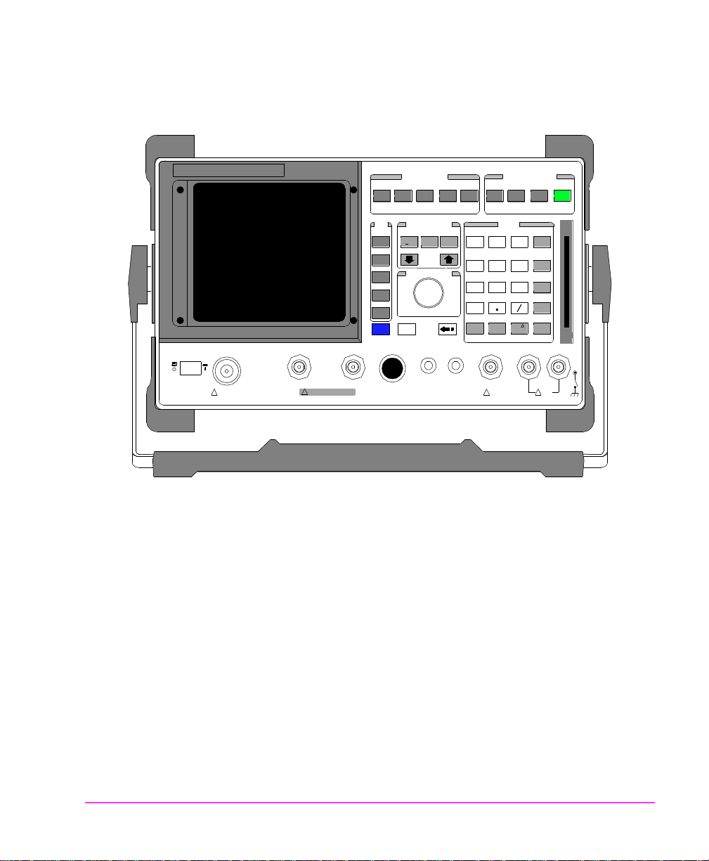
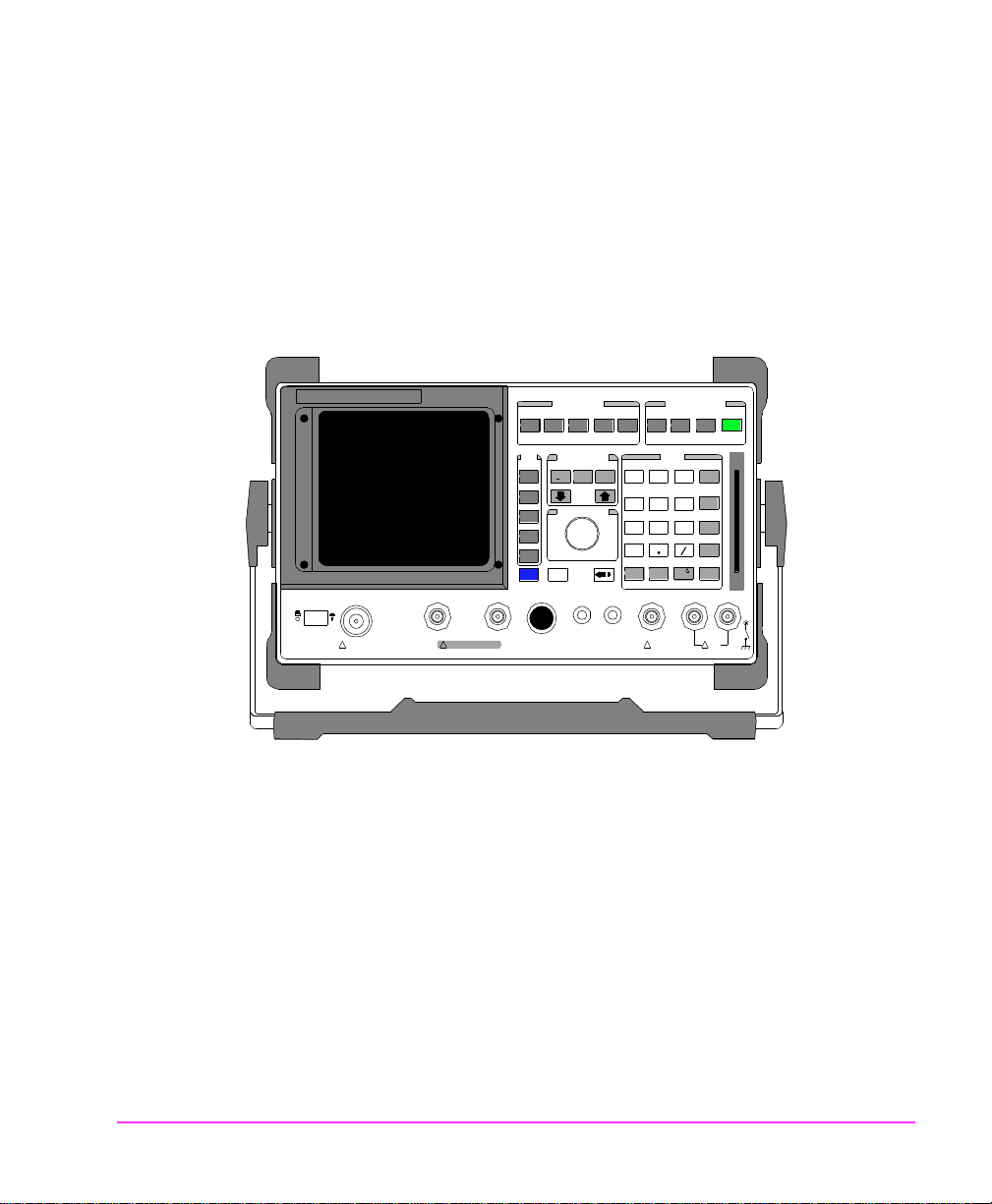
The Test’s Sets Front-Panel Features
The Test Set’s Features
POWER
OFF ON
MAX POWER 60 W
!
CONTINUOUS
!
ANT INDUPLEX OUTRF IN/OUT
MAX POWER 200 mW
SCREEN CONTRO L
CONFIGHELPMSSG HOLD PRINT
DUPLEXTXRX PREV TESTS
DATA FUNCTIONS
USER DATA
REF SET
METER
INCR
INCR
: 10
SET
CURSOR CONTROL
PUSH TO SELECT
AVG
INCR X10
k1’
k1
k2’
k2
k3’
k3
ASSIGN
k4
RELEASE
k5
SHIFT
LO LIMIT HI LIMIT
CANCEL
INSTRUMENT STAT E
ADRS
SAVE
LOCAL
RECALL
789
456
123
+
0
ON/OFF
YES
Ω
NO
%
ppm
dBµV
W
AUDIO O UTSQUELCHVOLUMEMIC/ACC
MAX
!
12 v Pk
_
MEAS
RESET
ENTER
dB
GHz
dBm
%
MHz
V
s
kHz
mV
ms
Hz
µV
AUDIO IN
MAX
!
42 v Pk
PRESET
MEMORY
CARD
LOHI
Screens
The CRT displays the various test scree ns, measurement results,
waveforms, and messages. The a brief description is provided in the
following:
• “Screens that are Standard to the Test Set” on page 30.
• “Screens that Require an Option” on page 31.
• “Screens that Require an Optional Instr u ment” on page 31.
29
Page 31

The Test Set’s Features
Screens that are Standard to the Test Set
•RX Test − receiver test s cre en with RF and audio output contro ls and
receiver measurement results.
•TX Test − transmitter test screen with RF and aud io input/output controls
and tran smitter meas urement results.
•Duplex Test − transmitter and rec eiver simultaneous test scree n with RF
and audio inp ut/output controls and transmitte r and receiver measur ement
results.
•Tests − access to creation, editing, copying, and execution of aut omated test
programs loaded from Memory Cards, int ernal ROM/RAM, or an external
disk drive.
• RF Generator − used to cont rol and d ispla y t he RF and m odul ation signa ls.
•RF Analyzer − used to proce ss and display RF signal measurements.
•AF Analyzer − used to process and display audio signal meas urements.
• Oscilloscope − used t o display the osci lloscope measurement function, with
vertical, time, trigger, and marker controls.
• Configure − used to control the various functions including date, screen
intensity, various RF controls, etc.
• I/OConfigure − used to control the various functions including HP-IB,
serial parameter, etc.
• Print Configure − used to setup a printer.
• Adjacent Channel Power − us ed to con trol measuri ng powe r of signa ls at a
specif i c ch an n e l s p ac in g above and be l ow th e RF A na ly z er ’ s center
frequency.
30
Page 32

The Test Set’s Features
Screens that Require an Option
• Spectrum Ana ly z er − used to display the spectrum analyzer measurement
function, with cent er frequency, s pan, reference le vel, marker, and tracking
generator controls .
• Encoder − used to display the si gnalling encoder function, with function
generator, tone sequence, DTMF, CDCSS, di gital pa ging, cellular an d LTR
and EDACS trunking subscre ens .
•Decoder − used to display the decoded data signalli ng with function
generator, tone sequence, DTMF, CDCSS, di gital pa ging, cellular an d LTR
and EDACS trunking subscre ens .
• Radio Interface − used to control the vario us functions of the optional rad io
interface.
• Call Control − used to test AMPS TACS Cellular radios.
Screens that Require an Optional In strument
• TDMA Test
•PDC Test
•PHP Test
• CDMA Test
• CDMA Analyzer
• CDMA Generator
• Code Domain
• Call Control
31
Page 33

The Test Set’s Features
User Keys
K1
REF SET
k1
K2
LO LIMIT HI LIMIT
k2
K3
k3
k4
k5
CANCELSHIFT
DATA FUNCTIONS
METER
INCR
INCR
: 10
SET
CURSOR CONTROL
PUSH TO SELECT
AVG
INCR
X10
7
4
1
0
YES
ON/OFF
USER
ASSIGN
RELEASE
User k1 - k5 keys − referred to as local keys, these keys enable you to
instantly enable a field for fast or repetitive acces s. Local keys functi on
for fields on the screen being displ ayed only.
User k1’ - k3’ keys
− referred to as global keys, these keys enable you
to display and control a field from another screen while viewing
another screen.
To Assign a User Key
1.
Select the screen which the desired field is on.
2. Position the cursor at the desired field using the Knob.
3. Press the ASSIGN key.
4. Press the desired k1-k5 or k1’-k3’ key.
32
To Un-assign a User Key
1.
Select the screen which the desired field is on.
2. Position the cursor at the desired field using the Knob.
3. Press and release the SHIFT key.
Press the RELEASE key.
4.
5. Press the ENTER key.
Page 34

Data Function Keys
The Test Set’s Features
K1
REF SET
k1
K2
LO LIMIT HI LIMIT
k2
K3
k3
k4
k5
CANCELSHIFT
DATA FUNCTIONS
METER
INCR
INCR
: 10
SET
CURSOR CONTROL
PUSH TO SELECT
AVG
INCR
X10
7
4
1
0
YES
ON/OFF
USER
ASSIGN
RELEASE
•The INCR ÷ 10, INCR SET, and INCR X10 keys change the increment/
decrement field value (units, tens, hundreds , etc).
• The keys increment/decrement field values, select among
various field choices, or move the cursor within fields.
• The LO LIMIT and HI LIMIT key s set measure ment limits for PASS/FAIL
indications .
• The REF SET key sets or removes a measurement reference f or rela tive
AF and RF measurements.
• The METER key enables/disables the analog bar-graph meter.
• The AVG key enables/disables measurement averaging.
33
Page 35

The Test Set’s Features
U
Knobs
K1
REF SET
k1
K2
LO LIMIT HI LIMIT
k2
K3
k3
k4
k5
CANCELSHIFT
DATA FUNCTIONS
METER
INCR
INCR
: 10
SET
CURSOR CONTROL
PUSH TO SELECT
AVG
INCR
X10
SQUELCHVOLUMEMIC/ACC
7
4
1
0
YES
ON/OFF
A
OUT
USER
ASSIGN
RELEASE
ANT IN
The Cursor Control Knob
• Moves the cursor to another field (rotate CW/CCW).
• Selects fields, scree ns, and settings from a list of choices. (push).
• Increments and decrements numeric field values (push to select, rotate the
knob to increment or decrement the value, then push again to enter).
Volume and Squelch Knobs
VOLUME Control − adjusts the speaker volume for monitoring.
SQUELCH Control
− adjusts the squelch thresho ld for AM, FM, or
SSB signals.
34
Page 36

Screen C o nt ro l Keys
P
The Test Set’s Features
SCREEN CONTROL
CONFIGHELPMSSG HOLD P RINT
DUPLEXTXRX PREV TESTS
DATA FUNCTIONSUSER DATA
INSTRUMENT STATE
ADRS
LOCAL
RECALL
SAVE
MEAS
RESET
These keys are used to access several instrument control and
information screens.
• RX key − displays the RX TEST screen for test of receivers.
• TX key − displays the TX TEST screen for test of transmitters.
• DUPLEX key − displays the DUPLEX TEST screen for simultane ous test
of transmitters/receivers.
•PREV key − returns the display to the prev ious screen.
• TESTS key − displays the TESTS (MAIN) screen used to access automated
test program functions.
• MSSG key − displays any error or operation messages since power- up.
• HELP key − displays the HELP screen that provides operating assistance.
• CONFIG key − displays the CONFIGURE screen defining general
operating functions.
• HOLD key − stops all me as urements. Selecting again resumes
measurement.
• PRINT key − prints the e ntire cont ents of the di splayed screen, the ti me and
date, and any previously defined print title ( if a printer is connected).
35
Page 37

The Test Set’s Features
Instrument State Keys
SCREEN CONTROL
CONFIGHELPMSS G HOLD PRINT
DUPLEXTXRX PREV TE STS
DATA FUNCTION SUSER DATA
INSTRUMENT STATE
ADRS
SAVE
LOCAL
RECALL
MEAS
RESET
PRESET
• LOCAL key − returns the instrument to manual control afte r HP- IB contr ol
is used.
• RECALL key − lists and selects a previously stored instrument setup.
• MEAS RESET key − clears the measurement “history” for all of the
instrument’s meas urement algorithms, and re-starts all measurements that
were in progress.
•PRESET key − restor es most instrument settings to th eir factory default
states. (Configure settings are not affected.)
• ADRS key − displays the current HP-IB address.
• SAVE key − stores an instrum en t setup.
36
Page 38

Data Keys
The Test Set’s Features
K1
REF SET
k1
K2
LO LIMIT HI LIMIT
k2
K3
k3
k4
k5
CANCELSHIFT
DATA FUNCTIO NS
METER
INCR
INCR
: 10
SET
CURSOR CONTROL
PUSH TO SELECT
AVG
INCR
789
X10
456
123
0
YES
ON/OFF
ENTER
dB
GHz
dBm
%
MHz
V
s
kHz
_
+
mV
ms
Ω
NO
ppm
W
dBµV
Hz
%
µV
MEMORY
CARD
USER DATA
ASSIGN
RELEASE
Data Entry keys− used to enter or change alphanumeric da ta (0-9, A-F,
“.”, “+”, or “−”) for measur ements or f ield entries . The EEX key i s us ed
to enter the exponent for scientific notation.
Termination keys
− used to input the entered data in the units selected.
Also allows entry of “YES” or “NO” to confirm selected opera tions
before they are executed.
• ENTER key − selects a field or screen, and enters numbers when the unit-
of-measure is not chang ed or not specified.
• ON/OFF key − enables and disables measurements, and turns numeric
fields (such as Amplitude ) on and off.
37
Page 39

The Test Set’s Features
POWER
OFF ON
MAX POWER 60 W
!
CONTINUO US
Connectors
CANCELSHIFT
!
ANT IN
MAX POWER 20 0 mW
DUPLEX OUTRF IN/OUT
ON/OFF
W
AUDIO OUTSQUELCHVOLUMEMIC/ACC
MAX
!
12 v Pk
AUDIO IN
MAX
!
42 v Pk
MEMORY
CARD
LOHI
µV
dBµV
Hz
%
ppm
RF IN/OUT Connector − type-N female connector for output signals
from the RF Generator, and input signals (60 Watts continuous, or 100
Watts for 10 sec/min) to the RF Analyzer. Nominal impeda nce is 50
Ω..
DUPLEX OUT Connector
− female BNC connector for output RF
Generator and Tracking Ge nerat or signals. Nominal impedanc e is 50Ω.
ANT IN Connector
low-power RF signals (
− female BNC connector for input and analysis of
≤200 m Watts), and for off-the-air
measurements. Nominal impedance is 50Ω.
MIC/A CC Connect or
− 8-pin female DIN connector provides various
connections includin g:
• Audio microphone input for modulation of the RF output signal
• Control of the RF Generator’s output s tate
• Switching between the TX TEST and RX TEST screens
• Provides keying signal to control a transmitter under test
AUDIO OUT Connector − female BNC connector to output signals
from AF Generators 1 and 2 (including encoder functions). Nominal
output impedance is%<1Ω at 1 kHz.
AUDIO IN Connectors
signals to the AF Analyzer. Nominal impedance is 1 M
• HI is the signal input for both grounding and floating input configurat ions.
• LO may be selected to connect the s ignal reference t o ground or float. T he
connectors and controls located on the rear panel are as follows:
− two female BNC connectors to input audio
Ω or 600Ω.
38
Page 40

K3
456
dBm
POWER
FON
The Test Set’s Features
Non-Bracketed Keys and Memory Card Slot
CURSOR CONTROL
k3
ASSIGN
k4
RELEASE
k5
DUPLEX OUTRF IN/OUT
ANT IN
PUSH TO SELECT
CANCELSHIFT
123
0
YES
NO
ppm
ON/OFF
W
AUDIO OUTSQUELCHVOLUMEMIC/ACC
_
+
Ω
%
dBµV
%
MHz
V
s
kHz
mV
ms
Hz
µV
AUDIO IN
MEMORY
CARD
LOHI
Non-Bracketed Keys
The POWER key − turns the instrument on or off.
The SHIFT key is used to select the blue -labeled functions listed above
certain keys.
The CANCEL key is used to cancel an entry in progress, or stop a
running IBASIC program.
The key is used to move the cursor to the left when entering
numbers in a field, thereby erasing the previous characters.
The Memo ry Card Sl ot
Slot for memory cards that are inserted to load software, or to record
test results.
39
Page 41

The Test Set’s Features
The Test Set’s Rear-Panel Features
HP-IB
(OPTIION)
(OPTIION)
PARALLEL PORT
SERIAL PORT
(OPTION)
CRT VID EO
MODULATION
DC CURR ENT
MEASUREMENT
INPUT
Connectors
• HP-IB Connector (optional) − 24-pin connector provides communication
between the Test Set a nd other instruments or a computer using the IEEE
488 Hewlett-Packard Interface Bus (HP-IB).
• SERIAL PORT Connector (optional) − 6-pin RJ-11 dual serial (RS-232 C)
port for entering prog ram s , printing test results and screen im age s, and
sending test re su lts to external devices.
• DC CURRENT MEASUR EMENT Terminals (optional) − dual banana
jacks to measure from 0 to +10 ADC.
• MODULATION INPUT Connector − female BNC connector to input an
external signa l to the modulators. Maximum input level is 12 V peak (full
scale input = 1 V peak), and nominal input impedance is 600Ω.
• CRT VIDEO OUTPUT Connector − female BNC connector provi des CRT
video to an external “multisync” video monitor.
OUTPUT
EXT SCOPE
TRIGGER
10 MHz REF
OUTPUT
10 MHz REF
INPUT
AUDIO
MONITOR
OPTION INTERFACE
114.3
MHz
IF
HEADPHONE
RF IN
DC
FUSE
DC INPUT
15A 11-32 VDC
CONTROL IO
IQ
CW RF
IN
AC DC
AC FUSE
5A 250V
40
Page 42

The Test Set’s Features
• EXT SCOPE TRIGGER INPUT Connector − female BNC connector to
input an external oscilloscope tri gger. Maximum input leve l is ≈ 20 V peak.
• 10 MHz REF OUTPUT Connector − female BNC connector outputs a 10
MHz reference signal for locking external instruments.
• 10 MHz REF INPUT Connector − female BNC connector to input an
external 1, 2, 5, or 10 MHz reference signal.
• AUDIO MONITOR OUTPUT Connector − female BNC connector
provides an output from the AF Analyzer. Level is not affected by the
VOLUME control, but is affected by the SQUELCH control.
• Chassis Ground Termin al − provi des a c hassis conne ction. Also provi des a
safety ground when DC power is used.
• RADIO INTERFACE Connector (optional) − 37 pin “D” style conne ctor
for parallel and serial communications, and audio/transmitter control lines
between the Test Set and external radio equipment.
• DC INPUT Connector − 2-pin female connecto r to input 11-28 Vdc @
120W (maximum) for DC operation.
• AC INPUT Connector − 3-pin male connector to input 100 to 240 Vac for
AC operation.
Key and Fuse Holders
•AC/DC− selects the instrument’s power source.
• DC FUSE Holder − 15A 250V fuse for DC operation.
• AC FUSE Holder − 5A 250V fuse for AC operation.
41
Page 43

The Test Set’s Features
42
Page 44

2
Measurements Considerations
The following guideline s must be adhered to when performing any of
the FM/AM /SSB Transmit t er and Rece iver, Spectru m An al yzer, or
Oscilloscope Measurements.
43
Page 45

Measurement Guideline 1
Measurement Guideline 1
Connector Considerations
CAUTION: The RF present at any Test Set input connector must not exceed the specified
level or permanent instr ument damage may resul t. If necessary , use an extern al
attenuator. I f ov erpo wer occurs , di scon nect the T rans mitter, t hen c ycle Test Set
power OFF/ON to reset the protection circuitry.
RF IN/OUT
The RF present at the Test Set RF IN/OUT connector must not exceed
60W continuous (or 100 Watts for 10 sec/minute) or permanent
instrument damage may result.
ANT IN
The RF present at the Test Set ANT IN connector must not exceed 200
mW or permanent instrument damage may result.
44
Page 46

Measurement Guideline 2
Cabling and Adapter Considerations
For most FM, AM, and SSB measurements, only the standard Test Set
with correct interco nnecting cables and adapters are required.
Output Power
If output power is greater than 60W (continuous), an external
attenuator is also requir ed. Any other additional equipment or Test Set
options that are required to perform the meas urement are listed in the
procedure.
Cabling Test Loads
When measuring audio output, a Test Load with a resista nce value
dependent on the Receiver’s output impedance (normally 8 Ω) is
required. In most cases, a non-inductive resistor with a power rating
sufficient for the Receiver’s rated o utput power and resistance that
matches the speaker impedance can be used. Typically, the test load is
connected at the Test Set AUDIO IN connector using a BNC to dual
banana adapter.
Measurement Guideline 2
Spectr u m A na l yz er
For Spectrum Analyzer measurements, the Spectrum Analyzer/
Tracking Generator opti on (002) must be installed in the Test Set.
Oscilloscope
For Oscilloscope Measurements, Hewlett-Packard’s HP 104XX series
passive Oscilloscope probes can be used to input signals to the
Oscilloscope via the front panel Audio Input or rear panel
MODULATION INPUT connectors.
45
Page 47

Measurement Guideline 3
Measurement Guideline 3
Special Test Considerations
Information for pe rfor ming any of the FM, AM, or SSB measur ements:
Coaxial Cable
Use short runs of high quality coaxial cable and high quality adapters
when connecting the device connected to the Test Set to ensure the
most accurate power measurement. Double shielded coaxial cable is
recommended when performing measurements on Cavities and
Duplexers.
Cable and Adapter Loss
Remember that cable and adapter losses and mismatch must be
considered when measuring RF power at VHF/UHF frequencies. If
losses are known, they can be entered using the CONFIGURATION
screen. Once entered, the measurement results are adjusted
accordingly.
46
Incidental Audio
Incidental audio into a built-in or attached microphone may cause
inaccurate readings. Whenever possible, disable the microphone input
or minimize ambient audio during the measurement.
Transmitter’s DTMF, CTCSS, and or CDCSS Functions
Verify that the Transmi tter’s DTMF, CTCSS, and/or CDCSS func tions
are OFF (if equipped), unless otherwise specified.
Receiver Test Loads
If using the Test Load, the measurement must be perfor med with only
the load connected to the Receiver’s audio output circuitry (internal
speaker disconnected). If the external speaker jack does not break the
Page 48

Measurement Guideline 3
internal speake r connection, either the Te st Set AUDIO IN signal must
be connected across the speaker (in this case, enter the impedance
value of the speaker in lieu of the test load resistance), or the internal
speaker must be physically dis connected.
Measuring Audio Output Power
When measuring audio output power in watts, alwa ys set Ext Load R
field to the Receiver’s audio output impedance or to the test load
resistance (when connected). Failure to do so will cause the
measurement to be incorrect.
Coded Squelch
Certain receivers use CTCSS, CDCSS, or trunked rad io signalling
coded squelch. If the receiver is equipped with a coded squelch device
that cannot be easily overridden, then the instruments AFGen2 or
Encoder must be used to open the squelch for measurement. Also, if
any of these are us ed, se t Filt er1 to 300Hz HPF to re move the t one use d
to open the squelch prior to measurement. Refer to the “RX” or
“Encoder” screen sections in the Test Set User’s Guide supplied with
the instrument for more information.
47
Page 49

Measurement Guideline 4
Measurement Guideline 4
Additional Measurement Considerations
Pressing the PRESET and TX or RX keys at the beginning of each te st
automatically configur es the Test Set for “standard” transmitter/
receiver measurements. The controls and settings that need to be
adjusted during performance of the measurement are discussed in each
procedure. Additional parameters or controls that may need to be
adjusted when testing a particular radio are describ ed in the “TX ”,
“RX”, “Spectrum Analyzer”, “Encoder”, and “Decoder” screen
sections of the Test Set User’s Guide supplied with the instrument.
48
Page 50

3
Testing FM Radios
49
Page 51

Introduction
Introduction
Each procedure may contain the following information:
• A brief measurement ov erview and a refe rence to appli cable TI A/EIA specifications for each test.
• A list of the T es t S et options and additional tes t equipment required to perform the procedure.
• Any special test considerations that need to be considered for safety, measurem ent accuracy , etc.
• Step by step procedu res required to perform e ac h measurement (with illustrations).
Refer to "Configuring for Measurements" on p age 243, or the Test Set’s
User Guide on preparing the Test Set for operation.
50
Page 52

List of Tests
List of Tests
FM Transmitter Measurements
"FM Off The Air Monitoring/Determining Unknown Transmitter
Carrier Frequency" on pa ge 53.
"FM Output Power, Deviation, and Frequency/Frequency Error
Measurement" on page 56.
"FM Deviation and Symmetry Measurement" on page 59.
"FM Microphone Sensitivity and Modulation Limiting Measurement" on page 62.
"FM CTCSS Encoder Frequency and Deviation Measurement" on
page 65.
"FM CDCSS Coding and Deviation Measurements" on page 67.
"FM DTMF Encodes and Deviation Measurement" on page 70.
"FM Audio Distortion Measurement " on page 74.
"FM Harmonics and Spurious Output Measurement" on page 76.
FM Receiver Measurements
"FM Audio Output Power Measurement" on page 80.
"FM SINAD, Receiver Center Frequency, and Modulation Acceptance Bandwidth Measurement" on page 83.
"FM Variation Of Sensitivity With Signal Frequency Measurement" on page 87.
"FM 20 dB Quieting Sensitivity Meas urem ent" on page 91.
"FM Critical and Maximum Squelch Sensitivity Measurement" on
page 94.
"FM CTCSS Sensitivity and Bandwidth Measurement" on page
97.
"FM CDCSS Sensitivity Measurement" on page 101.
"FM Audio Frequency Response Measurement" on page 105.
"FM Audio Distortion Measurement " on page 108.
"FM Spurious Response Attenuation Measurement" on page 111.
51
Page 53

FM Transmitters
FM Transmitters
The following measurements are pr ovided for testing FM Transmitte rs.
The procedures are arranged in the order that tests are typically performed.
52
Page 54

FM Transmitters
FM Off The Air Monitoring/Det erm ining Unknow n T ransm itte r Carrie r Frequency
Description
This procedure is used to locate, demodulate, and measure an FM
signal’s output carrier frequency. The low level signal is input to the
front-panel ANT IN connector, located, then demodulated using the
spectrum analyzer function.
NOTE: For performing an FM Off the Air Monitoring on a Known Transmitter
Carrier Frequency, see page 55.
If attempting to dete rmine the unknown frequency of a Trans mitter connecte d
to the RF IN/OUT connector, see “Output Power, Deviation, and Frequency
or Frequency Error Measurement” provided later in this chapter for the
measurement proc edure.
POWER
OFF ON
SPECTRUM ANALYZER
MAX POWER 60 W
!
CONTINUOUS
!
ANT INDUPLEX OUTRF IN/OUT
MAX POWER 200 mW
Knob
Data Entry
2
Keys
SCREEN CONTRO L
CONFIGHELPMSSG HOLD PRINT
DUPLEXTXRX PREV TESTS
DATA FUNCTIONS
USER DATA
REF SET
METER
INCR
INCR
: 10
SET
CURSOR CONTROL
PUSH TO SELECT
AVG
INCR X10
k1’
k1
k2’
k2
k3’
k3
ASSIGN
k4
RELEASE
k5
SHIFT
LO LIMIT HI LIMIT
CANCEL
INSTRUMENT STAT E
ADRS
SAVE
LOCAL
RECALL
789
456
123
+
0
ON/OFF
YES
Ω
NO
%
ppm
dBµV
W
AUDIO O UTSQUELCHVOLUMEMIC/ACC
MAX
!
12 v Pk
_
MEAS
RESET
ENTER
dB
GHz
dBm
%
MHz
V
s
kHz
mV
ms
Hz
µV
AUDIO IN
MAX
!
42 v Pk
PRESET
MEMORY
CARD
LOHI
1
53
Page 55

FM Transmitters
Test Set Options Required
Additional Equipment
Spectrum Analyzer/Tra cking Generator (option 102)
Whip antenna
Required
Measurement Procedure:
1 Connect the Antenna to the ANT IN connector.
CAUTION: Do not exceed the connector’s rated input or permanent instrument damage
may result .
On the Test Set:
2 Press the PRESET key.
❒ If monitoring an FM broadcast signal pe rform the following steps:
a Press the TX key.
b Use the knob to change IF Filter to 230 kHz.
c Continued to step 3.
❒ If not proceed to step 3.
Using the knob and data ent r y keys:
3 Select the SPEC ANL screen.
4 From the Control s select Ant.
5 Set Center Freq and Span fields to view desired spectrum.
6 Set Ref Level from −30 dBm to −50 dBm as required to vie w the desi red
signal.
54
Page 56

Once the desired carrie r is found:
7 From Controls, select Main.
8 Select Marker from the Choices field.
9 Use the Marker To field to select the desired carrier.
On the Test Set frequency and level are displayed as shown.
FM Transmitters
SPECTRUM ANALYZER
BW= 3 kH z
Marker
Freq
MHz
101.12980
Lvl
dBm
-99.92
Level & Frequency
displayed
10 To demodula te the carrier:
a With the m arker on the des ired ca rri er, s elec t Marker To to Center
Freq.
b From Controls, select Main.
c Select Marker from the Choices field.
d Decrease th e Span to 1.5 MHz (or less).
e Adjust the Volume and Squel ch controls to listen to th e demodulat-
ed carrier.
FM Off The Air Monitoring on a Known Transmitter Carrier Frequency
1 Press the PRESET key.
2 Press the TX key.
3 Set Tune Mode to Manual.
4 Set Tune Freq to known frequency.
5 Set Input Port to Ant
6 Set IF Filter to 230 kHz (if necessary).
55
Page 57

FM Transmitters
FM Output Power, Deviation, and Frequency/Frequency Error Measurement
Description
This procedure is used to measure an FM Transmitter’s output carrier
power and frequency (or frequency error) into 50 Ω. For FM
Transmitters, deviation and modulating frequency are also measured.
FM reference is ANSI/EIA-RS-152-C-1988, RS-316-C.
POWER
OFF ON
50Ω COXIAL
CABLE
MAX POWER 60 W
!
CONTINUOUS
3
TX TEST
USER DATA
k1’
k1
k2’
k2
k3’
k3
ASSIGN
k4
RELEASE
k5
SHIFT
ANT INDUPL E X OUTRF IN/OUT
MAX POWER 20 0 mW
!
ATTENUATOR (OPTIONAL)
TRANSMITTER UNDER TEST
1
Knob
SCREEN CONTRO L
CONFIGHELPMSSG HOLD PRINT
DUPLEXTXRX PREV TESTS
DATA FUNCTIONS
REF SET
METER
INCR
INCR
: 10
SET
LO LIMIT HI LIMIT
CURSOR CONTROL
PUSH TO SELECT
CANCEL
Data Entry
Keys
AVG
INCR X10
789
456
123
0
YES
ON/OFF
AUDIO O UTSQUELCHVOLUMEMIC/ACC
!
INSTRUMENT STAT E
ADRS
SAVE
LOCAL
12 v Pk
MEAS
RECALL
RESET
ENTER
_
+
Ω
NO
%
ppm
dBµV
W
AUDIO IN
MAX
!
SHEILDED
AUDIO CABLE
2
PRESET
dB
GHz
dBm
%
MHz
V
s
kHz
mV
ms
Hz
µV
MEMORY
CARD
LOHI
MAX
42 v Pk
56
ANTENNA
(RF OUT)
MICROPHONE
(AUDIO INPUT)
Page 58

Test Set Options Required
FM Transmitters
The typical error for the standard Test Set timebase is
2-3 Hz per 1 MHz (when measuring carrier frequency). If greater
accuracy is required, use a Test with Option 001 (High Sta bility
Timebase).
Special Test Considerations
"Cable and Adapter Loss" on page 46.
Measurement Procedure:
1 Connect the Transmitter Under Test as shown.
CAUTION: The RF present at the Test Set RF IN/OUT connector must not exceed 60W
continuous (or 100 Watts f or 10 sec/minute).
On the Test Set:
2 Press the PRESET key.
3 Press the TX key.
Using the knob and data entr y keys:
4 Set AFGen1 Lvl to the correct output level for the desired frequency devi-
ation (refer to microphone sensitivity and devi ation specifications for the
Transmitter being tested).
5 Set Filter 1 to 300 Hz HPF.
6 Set Filter 2 to 3 kHz LPF .
7 Set De-Emphasis to Off.
NOTE: If the Test Set is equipped with the CCITT filter option, set Filter 1 to
<20 Hz HPF and Filter 2 to CCITT.
57
Page 59

FM Transmitters
8. Determine if actual frequency readout or frequency error is the desired
measurement.
❒ For actual frequency readout, conti nue with step 9
❒ For frequency error:
•Set Tune Mode to Manual.
•Set Tune Freq to the expected carrier frequency.
On the Radio:
9 Key the Transmitter.
As long as the Tra n smitter is key ed the measurement results will display.
Frequency
Frequency
Output
Power
TX Freq E rror
TX Frequency
145.280024
TX Power
Tune Mode
Auto/Manual
Tune Freq
145.280000
MHz
TX Pwr Zero
Zero
TX TEST
MHz
0.169 3.579
kHz
TX TEST
FM Deviation
3.579
W
AF Fre q
2.03 1.00004
Input Port
RF in/Ant
IF Filter
15 kHz
Ext TX Key
On/Off
AF Anl In
FM De mod
Filter 1
300Hz HPF
Filter 2
3kHz LPF
De-Emphasis
750 us/Off
Detector
Pk+-Max
AFGen1 Freq
1.0000
MHz
AFGen1 Lvl
-45.5
dBm
Fre-
kHz
quency
kHz
kHz
To Screen
RF GEN
RF ANL
AF ANL
SCOPE
SPEC ANL
ENCODER
DECODER
RADIO INT
More
Modulating Fre-
58
Page 60

FM Deviation and Symmetry Measurement
This procedure is used to measure an FM Transmitter’s frequency
deviation and deviation symmetry. FM deviation is displayed on the
Test Set. Deviation symmetry requires measuring the plus and minus
peaks, then calculating symmetry.
FM Transmitters
POWER
OFF ON
50Ω COXIAL
CABL E
MAX POWER 60 W
!
CONTINUOUS
3
TX TEST
USER DATA
ASSIGN
RELEASE
SHIFT
ANT INDUPLEX OUTRF IN/OUT
MAX POWER 200 mW
!
ATTENUATOR (OPTIONAL)
TRANSMITTER UNDER TEST
1
Knob
k1’
k1
k2’
k2
k3’
k3
k4
k5
SCREEN CONTRO L
CONFIGHELPMS SG HOLD PRINT
DUPLEXTXRX PREV TESTS
DATA FUNCTIONS
REF SET
METER
INCR
INCR
INCR X10
: 10
SET
LO LIMIT HI LIMIT
CURSOR CONTROL
PUSH TO SELECT
CANCEL
Data Entry
Keys
ADRS
LOCAL
AVG
789
456
123
0
NO
YES
ppm
ON/OFF
W
AUDIO OUTSQUELCHVOLUMEMIC/ACC
MAX
!
12 v Pk
INSTRUMENT STAT E
SAVE
MEAS
RECALL
+
Ω
%
dBµV
_
RESET
ENTER
dB
GHz
dBm
%
MHz
V
s
kHz
mV
ms
Hz
µV
AUDIO IN
MAX
!
42 v Pk
PRESET
MEMORY
CARD
LOHI
SHEILDED
AUDIO CABLE
2
ANTENNA
(RF OUT)
MICROPHONE
(AUDIO INPUT)
59
Page 61

FM Transmitters
Measurement Procedure:
1 Connect the Transmitter Under Test as shown.
CAUTION: T he RF prese nt at the Tes t Set RF IN/O UT conne ctor mus t not exceed 60W
continuous (or 100 Watt s for 10 sec/minute).
On the Test Set:
2 Press the PRESET key.
3 Press the TX key.
On the Radio:
4 Key the Tran smit ter and keep ke yed un til t he rem aining step s are com plete .
On the Test Set using the knob and data entry keys:
5 Set AFGen1 Lvl so that displayed FM deviation is 60% of the Transmit-
ter’s specified maximum frequency deviation (typically 3 kHz).
On the Test Set m easured FM Deviation is displayed as shown.
60
Deviation
TX TEST
TX Frequency
144.680040
TX Power
kHz
W
FM Deviation
2.971
AF Fre q
0.591 1.00007
Tune Mode
Auto/Manual
Tune Freq
145.28 00 00
MHz
TX Pwr Zero
Zero
Input Port
RF in/Ant
IF Filter
15 kHz
Ext TX Key
On/Off
AF Anl In
FM De mod
Filter 1
300Hz HPF
Filter 2
3kHz LPF
De-Emphasis
750 us/Off
Detector
Pk+-Max
AFGen1 Freq
1.0000
AFGen1 Lvl
-45.5
To measure FM symmet ry on the Test Set:
6 Set Detector to Pk−.
7 Record the displayed FM Deviation as Pk−.
8 Set Detector to Pk+.
MHz
dBm
kHz
kHz
To Screen
RF GEN
RF ANL
AF ANL
SCOPE
SPEC ANL
ENCODER
DECODER
RADIO INT
More
Page 62

9 Record the displaye d FM Dev iation as Pk+.
Calcul ate the Me asu r ement:
10 Calculate the Deviation S ymmetry as follows:
FM Transmitters
Deviation Symmetry (in percent) =
For example, =
(3.010) - (2.971)
(3.010
(Pk +) - (Pk -)
(Pk +)
X 100 = 1.29
X 100
61
Page 63

FM Transmitters
FM Microphone Sensitivity and Modulation Limiting Measurement
Description
This procedure is used to measure an FM Transmitter’s audio input
sensitivity, and modulation limiting capability (if available).
Modulation limiting is verified over the Transmitter’s audio frequency
range. FM reference is ANSI/EIA-RS-152- C-1988 RS-316-B.
POWER
OFF ON
50Ω COXIAL
CABLE
MAX POWER 60 W
!
CONTINUOUS
3
TX TEST
USER DATA
k1’
k1
k2’
k2
k3’
k3
ASSIGN
k4
RELEASE
k5
SHIFT
ANT INDUPL E X OUTRF IN/OUT
MAX POWER 20 0 mW
!
ATTENUATOR (OPTIONAL)
TRANSMITTER UNDER TEST
1
Knob
SCREEN CONTRO L
CONFIGHELPMSSG HO LD PRI NT
DUPLEXTXRX PREV TESTS
DATA FUNCTIONS
REF SET
METER
INCR
INCR
: 10
SET
LO LIMIT HI LIMIT
CURSOR CONTROL
PUSH TO SELECT
CANCEL
Data Entry
Keys
AVG
INCR X10
789
456
123
0
YES
ON/OFF
AUDIO O UTSQUELCHVOLUMEMIC/ACC
!
INSTRUMENT STAT E
ADRS
SAVE
LOCAL
12 v Pk
MEAS
RECALL
RESET
ENTER
_
+
Ω
NO
%
ppm
dBµV
W
AUDIO IN
MAX
!
SHEILDED
AUDIO CABLE
2
PRESET
dB
GHz
dBm
%
MHz
V
s
kHz
mV
ms
Hz
µV
MEMORY
CARD
LOHI
MAX
42 v Pk
62
ANTENNA
(RF OUT)
MICROPHONE
(AUDIO INPUT)
Page 64

FM Transmitters
Special Test Considerations
See "Incidental Audio" on page 46.
Measurement Procedure:
1 Connect the Transmitter as shown.
CAUTION: The RF present at the Test Set RF IN/OUT connector must not exceed 60W
continuous (or 100 Watts f or 10 sec/minute).
On the Test Set:
2 Press the PRESET key.
3 Press the TX key.
Using the knob and data key s:
4 Set Filter 1 to 300 Hz HPF.
5 Set Filter 2 to 3 kHz LPF.
On the Radio:
6 Key the Transmitter and keep keyed u ntil the remaining steps are complet-
ed
On the Test Set using the knob and data entry keys:
7 Set AFGen1 Lvl so that displayed FM deviation is 60% of the Transmit-
ter’s specified frequency deviation (t ypically 3 kHz).
On the Test Set Microphone Sensitivity is shown as AFGen1 Lvl.
63
Page 65

FM Transmitters
TX TEST
TX Fr equenc y
145.280024
TX Power
kHz
W
FM Deviation
AF Freq
kHz
2.965
kHz
2.03 1.00004
Tune Mode
Auto/Manual
Tune Freq
145.280000
MHz
TX Pwr Zero
Zero
Inpu t P or t
RF in/Ant
IF Filter
15 kHz
Ext TX Key
On/O ff
AF Anl In
FM De mod
Filter 1
300Hz HPF
Filter 2
3kHz LPF
De-Emphasis
750 us/Off
Detector
Pk+-Max
AFGen1 Freq
AFGen1 Lvl
1.0000
-45.5
MHz
dBm
To Screen
RF GEN
RF ANL
AF ANL
SCOPE
SPEC ANL
ENCODER
DECODER
RADIO INT
More
Microphone
Sens it iv i ty
8 Set AFGen1 Lvl measurement units to dBm.
9 Increase AFGen1 Lvl by 20 dB.
Displayed FM deviation should not exceed the Transmitter’s maximum
specifie d deviation.
10 Change AFGen1 Freq from 300 Hz to 3 kHz (in 100 Hz increments).
64
11 Verify that the displayed FM deviation does not exceed the Transmitter’s
maximum specified deviation.
Page 66

FM CTCSS Encoder Frequency and Deviation Measurement
Description
This procedure is used to measure an FM Transmitter’s Continuous
Tone Coded Squelch System (CTCSS) encoder frequency and
frequency deviation. Both freq uency and deviat ion are read dir ectly off
the Test Set screen. FM referen ce is A NSI/ E IA RS-220-A.
FM Transmitters
POWER
OFF ON
50Ω COXIAL
CABL E
MAX POWER 60 W
!
CONTINUOUS
3
TX TEST
USER DATA
ASSIGN
RELEASE
SHIFT
ANT INDUPLEX OUTRF IN/OUT
MAX POWER 200 mW
!
ATTENUATOR (OPTIONAL)
TRANSMITTER UNDER TEST
1
Knob
k1’
k1
k2’
k2
k3’
k3
k4
k5
SCREEN CONTRO L
CONFIGHELPMS SG HOLD PRINT
DUPLEXTXRX PREV TESTS
DATA FUNCTIONS
REF SET
METER
INCR
INCR
INCR X10
: 10
SET
LO LIMIT HI LIMIT
CURSOR CONTROL
PUSH TO SELECT
CANCEL
Data Entry
Keys
ADRS
LOCAL
AVG
789
456
123
0
NO
YES
ppm
ON/OFF
W
AUDIO OUTSQUELCHVOLUMEMIC/ACC
MAX
!
12 v Pk
INSTRUMENT STAT E
SAVE
MEAS
RECALL
+
Ω
%
dBµV
_
RESET
ENTER
dB
GHz
dBm
%
MHz
V
s
kHz
mV
ms
Hz
µV
AUDIO IN
MAX
!
42 v Pk
PRESET
MEMORY
CARD
LOHI
SHEILDED
AUDIO CABLE
2
ANTENNA
(RF OUT)
MICROPHONE
(AUDIO INPUT)
65
Page 67

FM Transmitters
Measurement Procedure:
1 Connect the Transmitter as shown.
CAUTION: T he RF prese nt at the Tes t Set RF IN/O UT conne ctor mus t not exceed 60W
continuous (or 100 Watt s for 10 sec/minute).
On the Test Set:
2 Press the PRESET key.
3 Press the TX key.
On the Radio:
4 Key the Transmitter and keep keyed until the r em aining steps are complet-
ed.
On the Test Set using the knob and data entry keys:
5 Set Filter 2 to 300 Hz LPF.
On the Test Se t Tone frequenc y devi at ion is displ ayed a s FM Deviat ion as
shown.
66
On the Test Set Tone freque ncy is displayed as AF Freq.
TX TEST
AF Anl In
FM Demod
Filter 1
300Hz HPF
Filter 2
3kHz LPF
De-Emphasis
750 us/Off
Detector
Pk+-Max
FM Deviation
AF Freq
AFGen1 Freq
1.0000
AFGen1 Lvl
0.980
MHz
-45.5
dBm
kHz
kHz
To Scre en
RF GEN
RF ANL
AF ANL
SCOPE
SPEC ANL
ENCODER
DECODER
RADIO INT
More
Tone Deviation
Tone Frequency
TX Frequency
145.890058
TX Powe r
Tune Mode
Auto/Manual
Tune Freq
145.280000
MHz
TX Pwr Zero
Zero
kHz
W
0.587 0.10354
Input Port
RF in/Ant
IF Filter
15 kHz
Ext TX Key
On/Off
Page 68

FM CDCSS Coding and Deviation Measure ments
Description
This procedure is used to analyze an FM Transmitter’s Continuous
Digital Coded Squelch System (CDCSS) digital data stream and
frequency deviation. The data rate, binary data stream, and octal code
are all displayed on the Test Set screen.
FM Transmitters
POWER
OFF ON
50Ω COXIAL
CABLE
AF ANALYZER
DECODER
MAX POWER 60 W
!
CONTINUOUS
Knob
SCREEN CONTRO L
CONFIGHELPMSSG HO LD PRI NT
DUPLEXTXRX PREV TESTS
DATA FUNCTIONS
USER DATA
REF SET
k1’
INCR
k1
: 10
k2’
LO LIMIT HI LIMIT
k2
k3’
CURSOR CONTROL
k3
ASSIGN
k4
RELEASE
PUSH TO SELECT
k5
CANCEL
SHIFT
ANT INDUPLEX OUTRF IN/OUT
MAX POWER 200 mW
!
ATTENUATOR (OPTIONAL)
TRANSMITTER UNDER TEST
1
Data Entry
METER
AVG
INCR
INCR X10
SET
Keys
INSTRUMENT STAT E
ADRS
SAVE
LOCAL
RECALL
789
456
123
+
0
ON/OFF
YES
Ω
NO
%
ppm
dBµV
W
AUDIO O UTSQUELCHVOLUMEMIC/ACC
MAX
!
12 v Pk
_
MEAS
RESET
ENTER
dB
GHz
dBm
%
MHz
V
s
kHz
mV
ms
Hz
µV
AUDIO IN
MAX
!
42 v Pk
PRESET
MEMORY
2
CARD
LOHI
ANTENNA
(RF OUT)
67
Page 69

FM Transmitters
Test Set Options Required
Measurement Procedure:
1 Connect the Transmitter as shown.
CAUTION: T he RF prese nt at the Tes t Set RF IN/O UT conne ctor mus t not exceed 60W
continuous (or 100 Watt s for 10 sec/minute).
On the Test Set:
2 Press the PRESET key.
Using the knob and the data entry keys:
3 Select the AF ANL screen.
4 Set Filter 1 to <20 Hz HPF setting.
5 Set Filter 2 to 300 Hz LPF setting.
6 Set Settling to Slow setting.
7 Select the DECODER screen.
8 Set Mode to CDCSS.
9 Set Standard to CD CSS.
Decoder Option
68
10 Set Input Level to 0.95 kHz.
11 Set Arm Meas to Cont.
On the Radio:
12 Key the Transmitter and keep keyed until the r em aining steps ar e complet-
ed.
Data rate, binary data (bin), and the Octal Code(s) are displayed on the
Test Set as shown.
Page 70

FM Transmitters
NOTE: Because framing information to indicate when a code word is not sent, the
decoded data displayed can result in several possible code combinations as
shown. NPC may appear, indicating that no primary code matches the
decoded data.
SIGNALING DECODER
bps
Data Rate
Binary Data
Octa l Co de(s )
Data Rate
134.400
Data (bin)
1101100011000010101111
Code (oct )
143
333
To measure deviation of the data stream on the Test Set:
13 Press the TX key.
Data stream deviation is displayed as FM Deviation.
Arm Meas
Single/Cont
Stop Meas
AF Anl In
Audio Out
Input Level
1.0
Trig Leve l
242 mV
Polarity
Norm/Invert
Status:
Computing
Mode
CDCSS
Standard
CDCSS
V
To Sc reen
RF GEN
RF ANL
AF AN L
SCOPE
SPEC ANL
ENCODER
DECODER
RADIO INT
More
69
Page 71

FM Transmitters
FM DTMF Encodes and Deviation Measurement
Description
This procedure is used to measure an FM Transmitter’s Dual Tone
Multi-Frequency (DTMF) frequency, deviation and frequency
sequence (if desired).
POWER
OFF O N
50Ω COXIAL
CABLE
MAX POWER 60 W
!
CONTINUOUS
3
TX TEST
DECODER
DUPLEX OUTRF IN/OUT
ATTENUATOR (OPTIONAL)
1
ANT IN
MAX POWER 200 mW
!
TRANSMITTER UNDER TEST
Knob
Data Entry
Keys
SCREEN CONTROL
CONFIGHELPMSSG HOLD PRINT
DUPLEXTXRX PREV TESTS
DATA FUNCTIONS
USER DATA
k1’
REF SET
METER
AVG
INCR
INCR
: 10
SET
LO LIMIT HI LIMIT
CURSO R CONTR OL
PUSH TO SELECT
CANC EL
INCR X10
ASSIGN
RELEASE
SHIFT
k1
k2’
k2
k3’
k3
k4
k5
ADRS
LOCAL
789
456
123
0
NO
YES
ppm
ON/OFF
W
AUDIO O UTSQUELCHVOLUMEMIC/ACC
MAX
!
12 v Pk
INSTRU M E NT STATE
SAVE
MEAS
RECALL
RESET
ENTER
dB
GHz
dBm
%
MHz
V
s
kHz
_
+
mV
ms
Ω
Hz
%
µV
dBµV
AUDIO I N
!
42 v Pk
2
PRESET
MEMORY
CARD
LOHI
MAX
70
ANTENNA
(RF OUT)
Page 72

FM Transmitters
Test Set Options Required
Additional Equipment
Decoder Option
None
Required
Special Test Considerations
None
Measurement Procedure:
1 Connect the Transmitter as shown.
CAUTION: The RF present at the Test Set RF IN/OUT connector must not exceed 60W
continuous (or 100 Watts f or 10 sec/minute).
On the Test Set:
2 Press the PRESET key.
3 Press the TX key.
Using the knob and data entr y keys:
4 Set Filter 1 to 300 Hz HPF.
5 Set Filter 2 to 3 kHz LPF.
6 Select the DECODER screen.
7 Set Mode to DTMF.
8 Set Input Level to 0.95 kHz.
9 Set Gate Time to desired value (typically 100 ms).
10 Set Arm Meas to Cont.
On the Test Set:
11 Adjust Volume control to desired level.
12 Adjust Squelch control until just closed.
71
Page 73

FM Transmitters
On the Radio:
13 Key the Transmitter and keep keyed until the r em aining steps ar e complet-
ed.
14 Press the desired DTMF key.
The symbol and tone pair frequencies will be displayed on the Test Set as
shown.
DTMF Tone Pair
Sym
*
Lo Tone
Hi Tone
Freq
Freq
Hz
953.1 1226.9
SIGNALING DECODER
On
Time
Hz
ms
62.4 67. 2
Off
Time
ms
Arm Meas
Single/Cont
Stop Meas
Gate Time
1.5000 0
AF Anl In
FM Demod
Input Level
3.0
kHz
s
Status:
Idle
Mode
DTMF
Standard
Bell
To Sc reen
RF GEN
RF ANL
AF AN L
SCOPE
SPEC ANL
ENCODER
DECODER
RADIO INT
More
72
Page 74

To Measure deviation of the DTMF on the Test Set:
15 Press the TX key.
Tone deviation is displayed as FM Deviation.
TX TEST
TX Frequency
145.890058
TX Power
kHz
W
0.587 0.10354
FM Deviation
0.980
AF Freq kHz
kHz
Tone Deviation
Tone Frequency
❒ If decoding a sequence of DTMF tones, proceed as follows:
a Set Gate Time to a value long enough to ca pture the entire seque nce
(typically 1 to 5 seconds).
b Set Arm Meas to Single.
c Set Arm Meas (sta tus message will change to “ARMED”).
On the Radio:
d Key the Transmitter .
e Send DTMF sequence.
The symbols and tone pair fr eque ncies will be displayed on the
Test Set as shown.
FM Transmitters
DTMF Tone
Sequence
Sym
5
5
5
1
2
1
2
Lo Tone
Freq
Hz
770.9
770.8
770.9
770.4
770.6
770.3
770.6
Hi Tone
Freq
Hz
1341.2
1340.0
1340.4
1224.6
1340.6
1224.7
1340.7
SIGNALING DECODER
On
Off
Time
Time
ms
ms
109.8
109.9
111.2
107.6
112.8
108.3
116.4
106.0
112.3
102.7
111.7
107.7
106.6
Arm Meas
Single/Cont
Stop Meas
Gate Time
1.5000 0
AF Anl In
FM Demod
Input Level
3.0
kHz
s
Status:
Idle
Mode
DTMF
Standard
Bell
To Screen
RF GEN
RF ANL
AF ANL
SCOPE
SPEC ANL
ENCODER
DECODER
RADIO INT
More
73
Page 75

FM Transmitters
FM Audio Distortion Measurement
Description
This procedure is used t o measur e an FM Tr ansmitte r’s audio f requency
harmonic distortion level. FM referen ce is
ANSI/EIA-RS-152-C, RS-316-B.
POWER
OFF ON
50Ω COXIAL
CABLE
MAX POWER 60 W
!
CONTINUOUS
3
TX TEST
USER DATA
k1’
k1
k2’
k2
k3’
k3
ASSIGN
k4
RELEASE
k5
SHIFT
DUPLEX OUTRF IN/OUT
ATTENUATOR (OPTIONAL)
1
ANT IN
MAX POWER 20 0 mW
!
TRANSMITTER UNDER TEST
Knob
SCREEN CONTRO L
CONFIGHELPMSSG HO LD PRI NT
DUPLEXTXRX PREV TESTS
DATA FUNCTIONS
REF SET
METER
INCR
INCR
: 10
SET
LO LIMIT HI LIMIT
CURSOR CONTROL
PUSH TO SELECT
CANCEL
Data Entry
Keys
AVG
INCR X10
789
456
123
0
YES
ON/OFF
AUDIO O UTSQUELCHVOLUMEMIC/ACC
!
INSTRUMENT STAT E
ADRS
SAVE
LOCAL
12 v Pk
MEAS
RECALL
RESET
ENTER
_
+
Ω
NO
%
ppm
dBµV
W
AUDIO IN
MAX
!
SHEILDED
AUDIO CABLE
2
PRESET
dB
GHz
dBm
%
MHz
V
s
kHz
mV
ms
Hz
µV
MEMORY
CARD
LOHI
MAX
42 v Pk
74
ANTENNA
(RF OUT)
MICROPHONE
(AUDIO INPUT)
Page 76

FM Transmitters
Measurement Procedure:
1 Connect the Transmitter as shown.
CAUTION: The RF present at the Test Set RF IN/OUT connector must not exceed 60W
continuous (or 100 Watts for 10 sec/minute) or permanent instrument damage
may result.
On the Test Set:
2 Press the PRESET key.
3 Press the TX key.
Using the knob and data entr y keys:
4 Set Filter 1 to 300 Hz HPF.
5 Select the AF Freq Meter.
6 Select Distn from the Choices field.
7 Set AFGen1 Lvl so that displayed FM deviation is 100% of the Transmit-
ter’s specified maximum frequency deviation.
NOTE: Do not exceed the specified input level that causes maximum frequency
deviation, or the Transmitter’s modulation limiting circuits will cause added
distortion. R efer to the inp ut lev el /devia ti on spe cific at ion s for the T ransm itte r
being tested.
On the Radio:
8 Key the Transmitter and keep keyed until reading displays.
Distortion (in percent, or dB) is displayed on the Test Set as sh own.
TX TEST
TX Frequency
145.279974
TX Power
kHz
W
2.05 3.4
FM Deviation
4.847
Distn kHz
kHz
Deviation
Distortion
75
Page 77

FM Transmitters
FM Harmonics and Spurious Output Measurement
Description
This procedure is used to measure an FM Transmitter’s conducted
harmonic and spurious emissions. The spectrum analyzer option is
used to display harmonic and spurious components from 400 kHz to
1000 MHz. FM reference is ANSI/EIA-RS-152-C, RS-316-B.
POWER
OFF ON
50Ω COXIAL
CABLE
TX TEST
SPECTRUM ANALYZER
MAX POWER 60 W
!
CONTINUOUS
!
ATTENUATOR (OPTIONAL)
TRANSMITTER UNDER TEST
1
ANT INDUPL E X OUTRF IN/OUT
MAX POWER 20 0 mW
Knob
3
SCREEN CONTRO L
CONFIGHELPMSSG HO LD PRI NT
DUPLEXTXRX PREV TESTS
DATA FUNCTIONS
USER DATA
k1’
REF SET
INCR
k1
: 10
k2’
LO LIMIT HI LIMIT
k2
k3’
CURSOR CONTROL
k3
ASSIGN
k4
RELEASE
PUSH TO SELECT
k5
CANCEL
SHIFT
METER
AVG
INCR
INCR X10
SET
Data Entry
789
456
123
0
YES
ON/OFF
AUDIO O UTSQUELCHVOLUMEMIC/ACC
Keys
INSTRUMENT STAT E
ADRS
SAVE
LOCAL
RECALL
_
+
Ω
NO
%
ppm
dBµV
W
MAX
!
12 v Pk
SHEILDED
AUDIO CABLE
MEAS
RESET
ENTER
dB
GHz
dBm
%
MHz
V
s
kHz
mV
ms
Hz
µV
AUDIO IN
MAX
!
42 v Pk
PRESET
MEMORY
2
CARD
LOHI
76
ANTENNA
(RF OUT)
MICROPHONE
(AUDIO INPUT)
Page 78

FM Transmitters
Test Set Options Required
Spectrum Analyzer/Tracking Generator (option 102)
Cable and adapter mismatch must be considered when
measuring harmonics and spuri ous emissions of a transmitter. If an external attenuator is used, special care must
Special Test Considerations
be taken to ensure the attenuator is not causing any spurious or harmonic emission. Also, if spur ious e missions are
located, verify that the tr ansmitter is the source, and not
another object radiat ed emis sions near the test site
Measurement Procedure:
1 Connect the Transmitter as shown.
CAUTION: The RF present at the Test Set RF IN/OUT connector must not exceed 60W
continuous (or 100 Watts for 10 sec/minute) or permanent instrument damage
may result.
On the Test Set:
2 Press the PRESET key.
3 Press the TX key.
On the Radio:
.
4 Key the Transmitter and keep keyed u ntil the remaining steps are complet-
ed.
On the Test Set using the knob and data entry keys:
5 Set AFGen1 Lvl so that displayed FM deviation is 50% of the Transmit-
ter’s specified maximum frequency deviation (typically 2.5 kHz).
6 Set AFGen1 Lvl units to dBm.
7 Inc rease (mor e pos i ti v e) AFGen1 Lvl by 16 dB.
8 Select SPEC ANL.
9 Set Span to 1.1 MHz.
10 Set Ref Level to place the carrier peak at the top graticule line.
77
Page 79

FM Transmitters
To set Ref Level:
• From the Marker screen, select Marker To Peak
• Select Marker To Ref Lev el
11 Tune Center Freq in 1 MHz steps anywhere from 400 kHz to 1 GHz in
search of harmonics, sub-harmonics, multiples, or spurious emissions.
NOTE: If spurious emissions are suspect, un-key the Transmitter, and verify that
emissions are from the transmitter and not another source.
To measure spurious emission of the transmitter under test:
• Place at center frequency.
• Or perform the following:
a Select Main from the Controls field.
b Select Markers from the Choi ces field.
c Position the marker on the desired peak. (Position or Next Peak)
Marker frequency and level are displayed as shown.
78
SPECTRUM ANALYZER
BW= 3 kH z
Marker
Freq
MHz
101.12980
Lvl
dBm
-99.92
Spurious or Harmonic
Level & Frequency
Page 80

FM Receivers
FM Receivers
The following measurements are provi ded for testing FM Receivers.
The procedures are arranged in the order that tests are typically performed.
79
Page 81

FM Receivers
FM Audio Output Power Measurement
Description
This procedure is used to measure an FM Receiver’s maximum audio
output power (or rated output power) into a Test Load. Output powe r is
displayed (in various measurement units, including watts) on the Test
Set screen. The FM reference is RS-204D and RS-316B.
POWER
OFF O N
MAX POWER 60 W
!
CONTINUOUS
50Ω COXIAL
CABLE
ANTENNA (RF INPUT)
RX TEST
3
Knob
SCREEN CONTROL
CONFIGHELPMSSG HOLD PRINT
DUPLEXTXRX PREV TESTS
DATA FUNCTIONS
USER DATA
REF SET
METER
INCR
: 10
LO LIMIT HI LIMIT
CURSO R CONTR OL
PUSH TO SELECT
CANC EL
!
ANT INDU P L E X OUTRF IN/OUT
MAX POWER 200 mW
ASSIGN
RELEASE
SHIFT
k1’
k1
k2’
k2
k3’
k3
k4
k5
TEST LOAD
RECEIVER UNDER TEST
1
AVG
INCR
INCR X10
SET
Data Entry
Keys
INSTRUMENT STATE
ADRS
SAVE
RECALL
MEAS
RESET
LOCAL
789
456
123
_
0
YES
ON/OFF
+
Ω
NO
%
ppm
dBµV
W
AUDIO O UTSQUELCHVOLUMEMIC/ACC
!
12 v Pk
AUDIO IN
MAX
+
GND
ENTER
!
PRESET
dB
GHz
dBm
%
MHz
V
s
kHz
mV
ms
Hz
µV
MAX
42 v Pk
2
MEMORY
CARD
LOHI
SPEAKER
(AUDIO
INPUT)
80
Page 82

FM Receivers
Additional Equipment
Required
Special Test Considerations
Measurement Procedure:
1 Connect the Receiver as shown.
On the Test Set:
2 Press the PRESET key.
3 Press the RX key.
Using the knob and data entr y keys:
4 Set RF Gen Freq to the receiver operating frequency .
5 Set Amplitude to −47 dBm (1 mV).
6 Set AFGen1 To 60% of the Receiver’s specified maximum frequency de-
viation (typically 3 kHz).
7 Set Ext Load R to the test load resistance.
8 Set AC Level meter to measure Watts.
Test Lo ad
See "Receiver Test Loads" on page 46.
81
Page 83

FM Receivers
On the Radio set the Receiver’s Controls as follows:
9 Set power to ON.
10 If required, set frequency to the same value as step 4
11 Set squelch to minimum.
12 Set RF Gain to maximum (if equipped).
13 Set coded squelch feature (if equipped) to OFF.
Refer to "Coded Squelch" on page 47 for information on opening
Receivers with coded squelch.
14 Slowly increase volume control until the AC Level reaches the Receiver’s
rated output power, or reaches a maximum level (stop s increasing).
Refer to audio outp ut specifications for the Receiver being tested as
required.
NOTE: If the rated output cannot be obtained, tro ubleshoot and repair the Receiver’s
audio stages is necessary.
82
Measurement results are displayed on the Test Set as shown.
RX TEST
AFGen2 Freq
1.0000
AFGen2 To
FM
Off
AC Level
Hz
mV
0.06054
Filter 1
50Hz HPF
Filter 2
15kHz H PF
Ext Load R
8.00
To Screen
RF GEN
RF ANL
AF ANL
SCOPE
SPEC ANL
ENCODER
DECODER
RADIO INT
Ω
More
W
Audio (AF)
Output Power
SINAD
012.09
Avg
RF Ge n Fr eq
145.28 0000
Amplitude
Atten Hold
On/Off
Output Port
RF Out/Dupl
0.267
MHz
uV
AFGen1 Freq
1.0000
AFGen1 To
FM
3.00
dB
24
MHz
kHz
Page 84

FM Receivers
FM SINAD, Receiver Center Frequency, and Modulation Acceptance Bandwidth Measurement
Description
This procedure is used to measure an FM Receiver’s sensitivity (for
12dB SINAD), center frequency, and modulation acceptance
bandwidth. All measurements are read from the Test Set screen.
Reference is RS-204D.
POWER
OFF ON
MAX POWER 60 W
!
CONTINUOUS
50Ω COXIAL
CABLE
ANTENNA (RF INPUT)
RX TEST
3
Knob
SCREEN CONTRO L
CONFIGHELPMSSG HOL D PRINT
DUPLEXTXRX PREV TESTS
DATA FUNCTIONS
USER DATA
REF SET
METER
INCR
: 10
LO LIMIT HI LIMIT
CURSOR CONTROL
PUSH TO SELECT
CANCEL
!
ANT INDUPLEX OUTRF IN/OUT
MAX POWER 200 mW
ASSIGN
RELEASE
SHIFT
k1’
k1
k2’
k2
k3’
k3
k4
k5
TEST LOAD
RECEIVER UNDER TEST
1
AVG
INCR
INCR X10
SET
Data Entry
Keys
INSTRUMENT STAT E
ADRS
SAVE
RECALL
MEAS
RESET
LOCAL
789
456
123
_
0
YES
ON/OFF
+
Ω
NO
%
ppm
dBµV
W
AUDIO O UTSQUELCHVOLUMEMIC/ACC
!
AUDIO IN
MAX
12 v Pk
+
GND
ENTER
GHz
dBm
MHz
!
PRESET
dB
%
V
s
kHz
mV
ms
Hz
µV
MEMORY
MAX
42 v Pk
2
CARD
LOHI
SPEAKER
(AUDIO
INPUT)
83
Page 85

FM Receivers
Additional Equipment
Required
Spec ia l Test Consid eratio n s
Measurement Procedure:
1 Connect the Receive r as shown.
On the Test Set:
2 Press the PRESET key.
3 Press the RX key.
Using the knob and data ent r y keys:
4 Set RF Gen Freq to the receiver operating frequency.
5 Set Amplitude to −47 dBm (1 mV).
6 Set AFGen1 To 60% of the Receiver’s specified maximum frequency de-
viation (typically 3 kHz).
7 Set Ext Load R to the tes t loa d re s istance.
8 Set AC Level meter to measure Watts.
On the Radio set the Receiver’s Controls as follows:
Test Load
See "Receiver Test Loads" on page 46.
9 Set power to ON.
10 If required, set frequency to the same value as step 4
11 Set squelch to minimum.
12 Set RF Gain to maximum (if equipped).
13 Set coded squelch feature (if equipped) to OFF.
NOTE: Failure to set coded squelch to off will cause the SINAD measurement to be
incorrect.
14 Set the volume control until the AC Level reads 100% of th e Receiver’s rat-
ed audio output power.
84
Page 86

Refer to the audio output specifications for the receiver being tested.
On the Test Set using the knob and data entry keys:
15 Decrease Amplitude until the SINAD meter reads 12 dB.
Sensitivity (12dB SINAD) is displayed as Amplitude as shown.
• Record the level (in uv) for use in step 17.
RX TEST
AC Leve l
0.4527
SINAD
SINAD
0 14.00
Avg
uv
24
FM Receivers
W
Center
Frequency
Sensitivity
RF Gen Freq
146.519000
MHz
Amplitude
-119.4
dbm
Atten Hold
On/Off
Output Port
RF Out/Dupl
AFGen1 Freq
1.0000
AFGen1 To
FM
3.00
kHz
kHz
AFGen2 Freq
1.0000
AFGen2 To
FM
Off
kHz
Filter 1
50Hz HPF
Filter 2
15kHz H PF
Ext Load R
8.00
To Screen
RF GEN
RF ANL
AF ANL
SCOPE
SPEC ANL
ENCODER
DECODER
RADIO INT
Ω
More
❒ If desired, use the meter averaging functi on f or the SINAD indicator.
a Select dB on the SINAD meter.
b Press the AVG key.
❒ If desired, select the number of readings to average.
• Enter the number of readings to average.
Higher number of readings averaged will require longer to
reach the final indication.
❒ If desired, verify that the Receiver is tuned to a specific freque ncy (Re-
ceiver Center Frequency)
• Slowly increase or decrease RF Gen Freq (in 100 Hz steps) until
SINAD meter reads maximum.
Receiver Center F requen cy i s displa yed as RF Gen Freq as shown
above.
16 If changed because of the pr evious steps, re set RF Gen Freq to recei ver op-
erating frequency.
17 Set Am pl itud e to a level 6 dB higher (more po sit ive ) th an the lev el re cord -
ed in step 5.
18 Increase AFGen1 To Deviation until SINAD meter reads 12 dB.
85
Page 87

FM Receivers
On the Test Set modula tion acceptance bandwidth is displayed as
AFGen1 To Deviation as shown.
RX TEST
SINAD
012.08
Avg
dB
24
AC Level
0.6950
W
Modulatio n
Acceptance
Bandwidth
RF Gen Freq
146.519000
MHz
Amplitude
-119.4
dbm
Atten Hold
On/Off
Output Port
RF Out/Dupl
AFGen1 Freq
1.0000
AFGen1 To
FM
7.70
kHz
kHz
AFGen2 Freq
1.0000
kHz
AFGen2 To
FM
Off
Filter 1
50Hz HPF
Filter 2
15kHz HPF
Ext Load R
8.00
Ω
To Screen
RF GEN
RF ANL
AF ANL
SCOPE
SPEC ANL
ENCODER
DECODER
RADIO INT
More
86
Page 88

FM Variation Of Sensitivity With Signal Frequency Measurement
Description
This procedure is used to measure an FM Receiver’s usable bandwidth
(at 12 dB SINAD). A reference is establ ished (at 12 dB SINAD), then
the level is increased by 6 dB. Frequ en cy is increased and decreased
until the SINAD of 12 dB is again obtained. Usable bandwidth is then
calculated. Reference is EIA-204-D.
FM Receivers
POWER
OFF ON
MAX POWER 60 W
!
CONTINUOUS
50Ω COXIAL
CABLE
ANTENNA (RF INPUT)
RX TEST
3
Knob
SCREEN CONTRO L
CONFIGHELPMSSG HOL D PRINT
DUPLEXTXRX PREV TESTS
DATA FUNCTIONS
USER DATA
REF SET
METER
INCR
: 10
LO LIMIT HI LIMIT
CURSOR CONTROL
PUSH TO SELECT
CANCEL
!
ANT INDUPLEX OUTRF IN/OUT
MAX POWER 200 mW
ASSIGN
RELEASE
SHIFT
k1’
k1
k2’
k2
k3’
k3
k4
k5
TEST LOAD
RECEIVER UNDER TEST
1
AVG
INCR
INCR X10
SET
Data Entry
Keys
INSTRUMENT STAT E
ADRS
SAVE
RECALL
MEAS
RESET
LOCAL
789
456
123
_
0
YES
ON/OFF
+
Ω
NO
%
ppm
dBµV
W
AUDIO O UTSQUELCHVOLUMEMIC/ACC
!
AUDIO IN
MAX
12 v Pk
+
GND
ENTER
GHz
dBm
MHz
!
PRESET
dB
%
V
s
kHz
mV
ms
Hz
µV
MEMORY
MAX
42 v Pk
2
CARD
LOHI
SPEAKER
(AUDIO
INPUT)
87
Page 89

FM Receivers
Additional Equipment
Required
Spec ia l Test Consid eratio n s
Measurement Procedure:
1 Connect the Receive r as shown.
On the Test Set:
2 Press the PRESET key.
3 Press the RX key.
Using the knob and data ent r y keys:
4 Set RF Gen Freq to the receiver operating frequency.
5 Set Amplitude to −47 dBm (1 mV).
6 Set AFGen1 To 60% of the Receiver’s specified maximum frequency de-
viation (typically 3 kHz).
7 Set Ext Load R to the tes t loa d re s istance.
8 Set AC Level meter to measure Watts.
Test Load
See "Receiver Test Loads" on page 46.
88
Page 90

FM Receivers
On the Radio set the Receiver’s Controls as follows:
9 Set power to ON.
10 If required, set frequency to the same value as step 4.
11 Set squelch to minimum.
12 Set RF Gain to maximum (if equipped).
13 Set coded squelch feature (if equipped) to OFF.
NOTE: Failure to set coded squelch to off will cause the SINAD measurement to be
incorrect.
14 Set the volume control until the AC Level reads 100% of the Receiver’s rat -
ed audio output power.
Refer to the audio output specifications for the receiver being tested.
On the Test Set using the knob and data entry keys:
15 Decrease Amplitude until the SINAD meter reads 12 dB.
Sensitivity (12dB SINAD) is displayed as Amplitude as shown.
• Record the frequency as Assigned Freq for use later in the procedure.
RX TEST
AC Level
0.2775
W
Assigned
SINAD
0 11.97
Avg
dB
24
High, Low
8.00
To Screen
RF GEN
RF ANL
AF ANL
SCOPE
SPEC ANL
ENCODER
DECODER
RADIO INT
Ω
More
Frequency
RF Gen Freq
145.285900
MHz
Amplitude
-113.0
dbm
Atten Hold
On/Off
Output Port
RF Out/Dupl
AFGen1 Freq
1.0000
kHz
AFGen1 To
FM
7.70
kHz
AFGen2 Freq
1.0000
AFGen2 To
FM
Off
kHz
Filter 1
50Hz HPF
Filter 2
15kHz H PF
Ext Lo ad R
89
Page 91

FM Receivers
❒ If desired, use the meter averaging f unction for the SINAD indicator.
a Select dB on the SINAD meter.
b Press the AVG key.
❒ If desired, select the number of read ings to average.
• Enter the number of readings to average.
Higher number of readings averaged will requir e longer to
reach the fina l indication.
16 Increase Amplitude (more positive) by 6 dB.
17 Increase RF Gen Freq (in 100 Hz s teps) unti l the SINAD m eter again reads
12 dB.
• Record the frequency as High Freq for use lat er in the procedure.
18 Decrease RF Gen Freq (in 100 Hz step s) until the SINAD meter again
reads 12 dB.
• Record the frequency as Low Freq for use later in the procedure.
Calculate the measur ement:
19 High Freq − Assigned Freq and Assigned Freq − Low Freq
90
The minimum usable bandwidth is the smaller result.
Page 92

FM 20 dB Quieting Sensitivity Measure ment
Description
This procedure is used to measure an FM Receiver’s quieting
sensitivity (20 dB reduct ion in noise). A reference is established with
no signal at the Receiver’s antenna, then an un-modulated carrier is
applied and the RF amplitude is increased until a 20 dB reduction in
noise is measured at the audio output.
FM Receivers
POWER
OFF ON
MAX POWER 60 W
!
CONTINUOUS
50Ω COXIAL
CABLE
ANTENNA (RF INPUT)
RX TEST
3
Knob
SCREEN CONTRO L
CONFIGHELPMSSG HOL D PRINT
DUPLEXTXRX PREV TESTS
DATA FUNCTIONS
USER DATA
REF SET
METER
INCR
: 10
LO LIMIT HI LIMIT
CURSOR CONTROL
PUSH TO SELECT
CANCEL
!
ANT INDUPLEX OUTRF IN/OUT
MAX POWER 200 mW
ASSIGN
RELEASE
SHIFT
k1’
k1
k2’
k2
k3’
k3
k4
k5
TEST LOAD
RECEIVER UNDER TEST
1
AVG
INCR
INCR X10
SET
Data Entry
Keys
INSTRUMENT STAT E
ADRS
SAVE
RECALL
MEAS
RESET
LOCAL
789
456
123
_
0
YES
ON/OFF
+
Ω
NO
%
ppm
dBµV
W
AUDIO O UTSQUELCHVOLUMEMIC/ACC
!
AUDIO IN
MAX
12 v Pk
+
GND
ENTER
GHz
dBm
MHz
!
PRESET
dB
%
V
s
kHz
mV
ms
Hz
µV
MEMORY
MAX
42 v Pk
2
CARD
LOHI
SPEAKER
(AUDIO
INPUT)
91
Page 93

FM Receivers
Additional Equipment
Required
Spec ia l Test Consid eratio n s
Measurement Procedure:
1 Connect the Receive r as shown.
On the Test Set:
2 Press the PRESET key.
3 Press the RX key.
Using the knob and data e ntry keys:
4 Set RF Gen Freq to receiver operating frequency.
5 Set AFGen1 to OFF.
6 Set Amplitude to OF F .
7 Set Ext Load R to the tes t loa d re s istance.
8 Set AC Level meter to measure Watts.
Test Load
See "Receiver Test Loads" on page 46.
92
Page 94

FM Receivers
On the Radio set the Receiver’s Controls as follows:
9 Set power to ON.
10 If required, set frequency to same value as st e p 4.
11 Set squelch to minimum.
12 Set RF Gain to maximum (if equipped).
13 Set coded squelch feature (if equipped) to OFF.
Refer to "Coded Squelch" on page 47 for information on opening
Receivers with coded squelch.
14 Set the volume control until t he AC Level reads 25% of the Receive r’s rated
audio output power.
Refer to the audio output specifications for the receiver being tested.
On the Test Set using the knob and data entry keys:
15 Select AC Level
16 Press the REF SET key.
17 Increase Amplitude until the AC Level meter reads -20.00 dB.
On the Test Set 20 dB Quieting Sensitivity is displayed as Amplitude as
shown.
RX TEST
20 dB Quieting Sensitivity
SINAD
01.36
Avg
RF Gen Freq
145.280000
Amplitude
Atten Hold
On/Off
Output Port
RF Out/Dupl
0.501
MHz
uV
AFGen1 Freq
1.0000
AFGen1 To
FM
Off
dB
24
kHz
AFGen2 Freq
1.0000
AFGen2 To
FM
Off
AC Leve l
kHz
-20.34
Ref
Filter 1
50Hz HPF
Filter 2
15kHz H PF
Ext Load R
8.00
To Screen
RF GEN
RF ANL
AF ANL
SCOPE
SPEC ANL
ENCODER
DECODER
RADIO INT
Ω
More
dB
93
Page 95

FM Receivers
FM Critical and Maximum Squelch Sens itivit y Measu rem en t
Description
This procedure is used to measure an FM Receiver’s critical squelch
and maximum squelch sensitivity. For critical squelch, the receiver is
just squelched with minimum modulated input a t the Receiver’s
antenna, then the input is increas ed until the squelch is opened.
Maximum squelch is the amount of modulated signal required to open
the squelch when the control is set to maximum. Minimum and
maximum squelch hysteresis is also measured and calculated. The FM
reference is EIA/TIA-204-D.
POWER
OFF O N
50Ω COXIAL
CABLE
MAX POWER 60 W
!
CONTINUOUS
RX TEST
!
ANT IN
MAX POWER 200 m W
DUPLEX OU TRF IN/OUT
ANTENNA (RF INPUT)
3 Knob
Data Entry
Keys
SCREEN CONTROL
CONFIGHELPMSSG HOLD PRINT
DUPLEXTXRX PREV TESTS
DATA FUNCTIONS
USER DATA
k1’
REF SET
METER
AVG
INCR
INCR
k2’
k3’
ASSIGN
RELEASE
SHIFT
k1
k2
k3
k4
k5
INCR X10
: 10
SET
LO LIMIT HI LIMIT
CURSOR CONTROL
PUSH TO SELECT
CANCEL
789
456
123
0
YES
ON/OFF
AUDIO OUTSQUELCHVOLUMEMIC/ACC
!
RECEIVER UNDER TEST
1
INSTRUMENT STATE
ADRS
LOCAL
RECALL
NO
ppm
W
MAX
12 v Pk
SAVE
+
Ω
%
dBµV
_
MEAS
RESET
ENTER
dB
GHz
dBm
%
MHz
V
s
kHz
mV
ms
Hz
µV
AUDIO I N
!
2
PRESET
MEMORY
CARD
LOHI
MAX
42 v Pk
94
Page 96

FM Receivers
Special Test Considerations
Measurement Procedure:
1 Connect the Receiver as shown.
On the Test Set:
2 Press the PRESET key.
3 Press the RX key.
Using the knob and data entr y keys:
4 Set RF Gen Freq to the receiver operating frequency .
5 Set Amplitude to −137 dBm.
On the Radio set the Receiver’s Controls as follows:
6 Set power to ON.
7 If required, set frequency to the same value as step 4.
8 Set squelch to minimum.
9 S et RF Gain to maximum (if equipped).
10 Set coded squelch feature (if equipped) to OFF.
11 Set the volume control unt il noise is at a comfortable level.
See "Coded Squelch" on page 47.
12 Increase the Receiver’s sq uelch control until audio is just squelched.
95
Page 97

FM Receivers
On the Test Set using the knob and data entry keys:
13 Slowly increase the Amplitude until squelch just remains open.
Critical Squelch is displayed as Amplitude as shown.
• Re cord thi s level.
RX TEST
SINAD
02.23
Avg
dB
24
AC Leve l
-20.34
dB
Ref
8.00
Ω
To Sc reen
RF GEN
RF ANL
AF AN L
SCOPE
SPEC ANL
ENCODER
DECODER
RADIO INT
More
Squelch
Sensitivity
RF Gen Freq
145.280000
MHz
Amplitude
0.0890
Atten Hold
On/Off
Output Port
RF Out/Dupl
AFGen1 Freq
AFGen1 To
FM
uV
1.0000
3.00
kHz
kHz
AFGe n2 Fre q
1.0000
AFGe n2 To
FM
Off
kHz
Filter 1
50Hz HPF
Filter 2
15kHz H PF
Ext Load R
14 Decrease Amplitude until the Receiver’s squelch just closes.
• Re cord thi s level.
Calculate the measur ement:
15 Critical Squelch Hysteresis is the difference between the two readings.
On the Radio set the Receiver’s Controls as follows:
16 Set the Receiver’s s quelch control to maximum.
On the Test Set using the knob and data entry keys:
17 Increase Amplitude until the Receiver’s squelch just opens.
• Re cord thi s level.
18 Record the maximum squelch sensitivity is displayed as Amplitude as
shown.
19 Decrease Amplitude until the Receiver’s squelch just closes.
• Re cord thi s level.
96
Calcula te the reading:
20 Maximum Squelch Hysteresis is the differ ence between the two readings.
Page 98

FM CTCSS Sensitivity and Band w idth Measurement
Description
This procedur e is use d to measure an FM Receiver’s Continuous Tone Coded
Squelch System (CTCSS) sensitivity and bandwidth. For sensitivity, the
minimum signal inpu t at the Receiver’s antenna (modulated with tone) that
opens the squelch is measured and displayed. Squelch hysteresis is also
measured and calculated. Tone frequency is then increased and decreased until
the squelch boundaries are determined and the Bandwidth is calc ulated.
Reference is ANSI/EIA RS-220A.
FM Receivers
POWER
OFF ON
MAX POWER 60 W
!
CONTINUOUS
50Ω COXIAL
CABLE
ANTENNA (RF INPUT)
RX TEST
3
Knob
SCREEN CONTRO L
CONFIGHELPMSSG HOL D PRINT
DUPLEXTXRX PREV TESTS
DATA FUNCTIONS
USER DATA
REF SET
METER
INCR
: 10
LO LIMIT HI LIMIT
CURSOR CONTROL
PUSH TO SELECT
CANCEL
!
ANT INDUPLEX OUTRF IN/OUT
MAX POWER 200 mW
ASSIGN
RELEASE
SHIFT
k1’
k1
k2’
k2
k3’
k3
k4
k5
TEST LOAD
RECEIVER UNDER TEST
1
AVG
INCR
INCR X10
SET
Data Entry
Keys
INSTRUMENT STAT E
ADRS
SAVE
RECALL
MEAS
RESET
LOCAL
789
456
123
_
0
YES
ON/OFF
+
Ω
NO
%
ppm
dBµV
W
AUDIO O UTSQUELCHVOLUMEMIC/ACC
!
AUDIO IN
MAX
12 v Pk
+
GND
ENTER
GHz
dBm
MHz
!
PRESET
dB
%
V
s
kHz
mV
ms
Hz
µV
MEMORY
MAX
42 v Pk
2
CARD
LOHI
SPEAKER
(AUDIO
INPUT)
97
Page 99

FM Receivers
Additional Equipment
Required
Spec ia l Test Consid eratio n s
Measurement Procedure:
1 Connect the Receive r as shown.
On the Test Set:
2 Press the PRESET key.
3 Press the RX key.
Using the knob and data ent r y keys:
4 Set RF Gen Freq to the receiver operating frequency.
5 Set Amplitude to −47 dBm (1 mV).
6 Set AFGen1 To 60% of the Receiver’s specified maximum frequency de-
viation (typically 3 kHz).
7 Set AFGen2 Freq to the Receiver’s CTCSS tone f r equency.
8 Set AFGen2 To to th e 500 Hz.
9 Set Ext Load R to the test load re sistanc e.
Test Load
See "Receiver Test Loads" on page 46.
98
10 Set AC Level meter to measure Watts.
Page 100

FM Receivers
On the Radio set the Receiver’s Controls as follows:
11 Set power to ON.
12 If required, set frequency to the same value as step 4
13 If required, set CTCSS tone frequency to the same value as step 4
14 Set RF Gain to maximum (if equipped).
15 Set squelch control to mini mum (if equipped).
16 Set the volume control unt il the AC Level reads 100% of the Receiver’s
specified audio out put.
Refer to the audio output specifications for the receiver being tested.
17 Verify Receiver’s squelch is closed.
On the Test Set using the knob and data entry keys:
18 Set Amplitude to -137 dBm.
19 Slowly increase the Amplitude until the squelch remains ope n and the SI-
NAD indicator shows 10 dB (minimum).
CTCSS Sensitivity is displa yed as Amplitude as shown.
• Record this level.
RX TEST
SINAD
011.16
Avg
dB
24
AC Level
0.6321
W
CTCSS
8.00
To Screen
RF GEN
RF ANL
AF ANL
SCOPE
SPEC ANL
ENCODER
DECODER
RADIO INT
Ω
More
Squelch Sensitivity
RF Gen Freq
145.28 0000
MHz
Amplitude
0.282
Atten Hold
On/Off
Output Port
RF Out/Dupl
uV
AFGen1 Freq
1.0000
AFGen1 To
FM
3.00
kHz
kHz
AFGen2 Freq
100.0
AFGen2 To
FM
5.00
Hz
Hz
Filter 1
50Hz HPF
Filter 2
15kHz HPF
Ext Load R
20 Set Amplitude to −47 dBm.
21 Slowly increase the AFGEN2 Freq in 0.1 Hz incre ments unt il th e squ elch
just closes.
• Record the frequency.
22 Slowly decrease the AFGEN2 Freq in 0.1 Hz inc reme nts unt il the s quelc h
99
 Loading...