

Page 1

About this Manual
We’ve added this manual to the Agilent website in an effort to help you support
your product. This manual is the best copy we could find; it may be incomplete
or contain dated information. If we find a more recent copy in the future, we will
add it to the Agilent website.
Support for Your Product
Agilent no longer sells or supports this product. Our service centers may be able
to perform calibration if no repair parts are needed, but no other support from
Agilent is available. You will find any other available product information on the
Agilent Test & Measurement website, www.tm.agilent.com.
HP References in this Manual
This manual may contain references to HP or Hewlett-Packard. Please note that
Hewlett-Packard's former test and measurement, semiconductor products and
chemical analysis businesses are now part of Agilent Technologies. We have
made no changes to this manual copy. In other documentation, to reduce
potential confusion, the only change to product numbers and names has been in
the company name prefix: where a product number/name was HP XXXX the
current name/number is now Agilent XXXX. For example, model number
HP8648A is now model number Agilent 8648A.
Page 2

Installation and Service
Guide
Publication number 16500-97012
First edition, April 1995
For Safety information, Warranties and Regulatory information,
see the pages behind the index
Copyright Hewlett-Packard Company 1993, 1994, 1995
All Rights Reserved
HP 16500H Interface Module
Page 3

In This Book
This book shows you how to install and service the HP 16500H Interface
Module . This book contains the following chapters:
Chapter 1 provides and overview of the HP 16500H.
•
Chapter 2 shows you how to install the HP 16500H in the HP 16500B
•
mainframe. This chapter also provides information on where to go next,
depending on which environment you are using the HP 16500 system in.
Chapter 3 contains the procedures for performance verification and
•
replacing assemblies. This chapter tells you where to find information on
troubleshooting the system, depending on which environment you are
using the HP 16500B system in.
See Also
The
HP 16500H LAN Interface Module Administrator’s and Service
for information on installing and setting up the HP 16500H in the LAN
Guide
environment.
The
HP 16500B Logic Analysis System Setting UP the System Guide
information on installing and setting up an HP 16501A Expansion Frame.
The
HP 16505A Prototype Analyzer Installation Guide
installing and setting up an HP 16505A Prototype Analyzer.
The
Logic Analyzer Training Kit
operation of the HP 16500B system.
if you are unfamiliar with the basic
for information on
for
ii
Page 4

Contents
1 Introducing the HP 16500H Interface Module
Accessories Supplied 1–3
Requirements 1–3
Physical Connections 1–3
LAN Support 1–4
2 Installing the Interface Module
To Install the HP 16500H Hardware 2–2
To Verify the Installation 2–4
Ethernet LAN Interface 2–5
HP 16501A Expansion Frame Interface 2–7
HP 16505A Protoytype Analyzer 2–8
3 Servicing the Interface Module
Verify the Interface Module Performance 3–2
Troubleshooting an HP 16501A Expansion Frame 3–7
Troubleshooting in an Ethernet LAN Environment 3–8
Troubleshooting in the HP 16505A Prototype Analyzer Environment 3–9
Removing and Replacing the HP 16500H Interface Module 3–10
Returning Parts 3–13
Ordering Replaceable Parts 3–14
Replaceable Parts List 3–15
Contents-1
Page 5

Contents-2
Page 6

1
Introducing the HP 16500H 1-2
Accessories Supplied 1–3
Requirements 1–3
Physical Connections 1–3
LAN Support 1-4
Introducing the HP 16500H
Interface Module
Page 7
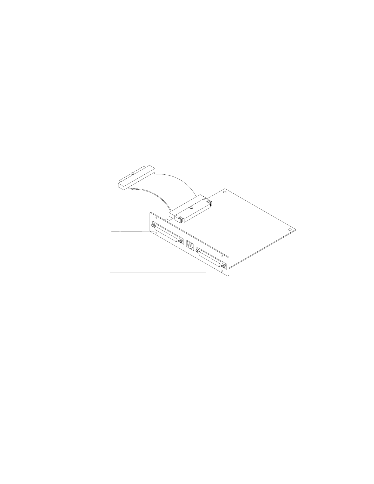
Introducing the HP 16500L LAN Interface
Module
The HP 16500H LAN interface module provides three capabilities for
your HP 16500 Logic Analysis System:
• connection to an Ethernet 10Base-T Local Area Network (LAN)
• connection to an HP 16501A Expansion Frame for the HP 16500B
Logci Analysis System
• a high-speed port for connecting the HP 16500B to an HP 16505A
Prototype Analyzer
Expander Frame
connector
Ethertwist
LAN connector
High-speed
port
The HP 16500H interface module
1–2
Page 8

Introducing the HP 16500H Interface Module
Accessories Supplied
Accessories Supplied
The HP 16500H is shipped with the following accessories:
Installation and Service Guide
this
•
LAN Administrator’s and Service Guide
a
•
LAN User’s Guide
a
•
screws and one cable to install the HP 16500H into the HP 16500B
•
mainframe
TORX 10 and TORX 15 wrenches
•
If your HP 16500H was installed into the HP 16500B by HP, you will
not receive these tools. If your HP 16500H was not installed by HP,
you will receive these tools.
Requirements
HP 16500B Logic Analysis System mainframe, and one of the following:
NFS or FTP capabilities on your TCP/IP Ethernet LAN, or
•
HP 16501A Expansion Frame, or
•
HP 16505A Prototype Analyzer
•
Physical Connections
RJ-45 connector for direct connection to 10Base-T networks
•
68-pin D-connector for connection to an HP 16501A Expansion Frame
•
High-speed port for connection to an HP 16505A Prototype Analyzer
•
1–3
Page 9

Introducing the HP 16500H Interface Module
LAN Support
LAN Support
For information about the LAN protocols and file types supported by the HP
16500H, refer to the
LAN Administrator’s and Service Guide
1–4
Page 10

2
This chapter includes procedures to install the interface module into
the HP 16500B Logic Analysis System mainframe and to verify the
installation.
For detailed information on how to install the HP 16500B in one of the
three applications supported by the interface module, refer to the
documentation for the specific application. This chapter provides
references to those other documents.
To Install the HP 16500H Hardware 2-2
To Verify the Installation 2-4
Ethernet LAN Interface 2-5
HP 16501A Expansion Frame Interface 2-7
HP 16505A Prototype Analyzer Interface 2-8
Installing the Interface Module
Page 11

WARNING
Installing the Interface Module
To Install the HP 16500H Hardware
To Install the HP 16500H Hardware
If you need instructions for removing and replacing parts of the HP 16500B,
refer to the
SHOCK HAZARD
performing the following procedures. After disconnecting the power, wait at
least six minutes for the capacitors on the power supply board and the CRT
driver board to discharge before servicing the instrument. Failure to do so
could result in electrical shock. Hazardous voltages exist on the power
supply, the CRT, and the CRT driver board of the HP 16500B mainframe. As
long as the AC LED on the power supply has any illumination, a significant
charge remains on the capacitors.
HP 16500B Logic Analysis System Service Guide
Disconnect the power from the mainframe before
.
CAUTION
Use grounded wriststraps and mats when performing any service to this
module or to the HP 16500B Logic Analysis System. Electrostatic discharge
can damage electronic components.
For correct orientation of the cables, match the slots on the cable connectors
and on the board connectors.
1
Remove power from the HP 16500B mainframe, then remove the
measurement modules, the four rear feet, and the top and bottom
covers of the mainframe.
2
Remove the sheetmetal plate on the rear of the mainframe covering
the slot where the interface module will be installed.
With the interface module installed, you will not use the plate. Save the plate
to use in case the interface module is removed.
2–2
Page 12
Installing the Interface Module
To Install the HP 16500H Hardware
3
Slide the interface module into the mainframe through the slot in the
rear panel.
4
Install the screws connecting the interface module to the mainframe.
Two screws through the top of the interface module connect it to the
sheetmetal plate, and four screws through the rear plate of the interface
module connect it to the rear panel of the mainframe.
5
Connect the 80-pin cable to the CPU board and to the interface
module.
Before installing the cable, inspect the cable and the connectors for
any signs of damage.
a
Slide the 80-pin cable halfway through the rear slot of the card cage
between the interface module and the CPU board.
b
Connect the cable to the CPU board.
c
Connect the cable to the interface module.
6
Replace the top and bottom covers, the optional modules, and the
rear feet of the mainframe.
Installing the Interface Module
2–3
Page 13

Installing the Interface Module
To Verify the Installation
To Verify the Installation
1
Check that "Ethernet" is available in the Communications menu of
the mainframe System Configuration menu.
When you power-up the mainframe, the Logic Analysis System performs the
power-up self-tests. After the self-tests are finished, the screen displays the
System Configuration menu. If the operating system finds an interface
module installed, then Ethernet is available in the Communications menu.
2
If "Ethernet" is not available in the Communications menu, go to
"Verifying the Interface Module Performance" in Chapter 3 of this
manual.
Verifying the Installation
Ethernet should be
listed here
2–4
Page 14

Installing the Interface Module
Ethernet LAN Interface
Ethernet LAN Interface
The LAN interface provides a network-based interface between the HP
16500B Logic Analysis System and personal computers and workstations over
a 10Base-T Ethernet LAN. Detailed information on installing and
troubleshooting in the LAN environment is covered in the
Administrator’s and Service Guide
the process with some troubleshooting hints.
1
Connect an EtherTwist 10Base-T LAN cable into the RJ-45 LAN port
. The following steps are an overview of
on the interface module.
If your LAN uses ThinLAN connections, a Media Access Unit (MAU) is
required.
2
Set up the configuration menus on the HP 16500B mainframe.
You can configure the interface module to work with your network from the
HP 16500B front-panel touchscreen. After the HP 16500B power-up tests are
complete, the Ethernet configuration can be accessed in the Communications
menu.
The interface module automatically obtains the subnet mask by sending a
broadcast ICMP query over the network. The broadcast ICMP query is
transmitted approximately 10 seconds after power is applied to the interface
module and approximately 2 seconds after the IP address is changed. When
the query is answered by another network device, the interface module
stores the information in internal memory.
HP 16500H LAN
2–5
Page 15

Installing the Interface Module
Ethernet LAN Interface
3
Verify connectivity with an echo request.
In most network environments, an echo request is accomplished using the
ping
utility. For the exact syntax for the
refer to your network documentation. A normal response to multiple echo
requests is 9, 10, or possibly 11 packets transmitted for every 10 echo
requests.
If there is no response to the echo request, first check the command line. If
an IP address is used in the echo request command line, then the IP address
typed in the command line should match the IP address stored in the
HP 16500B Ethernet Configuration menu. If a hostname was used in the
command line, then check the node names database to see that the IP
address and the hostname for the HP 16500B were correctly entered.
After verifying the command line, check to make sure the hardware is
connected and operating properly. To verify operation of the interface
module, refer to "To verify the interface module performance" in Chapter 3.
An intermittent response to the echo request indicates a problem with the
LAN itself. Use a LAN analyzer or LAN management software to monitor
activity and determine where bottlenecks or other problems are occurring.
4
Mount the HP 16500B system with an NFS mount.
An NFS mount of the 16500B system depends on the network environment
the system is being mounted to. For UNIX, the
computer name and mount point are required. In MS-DOS, a virtual drive
specifier and 16500B IP address are required. File Manager in MS-Windows is
used to mount in an MS-Windows environment. In all cases, either the
16500B file server /control or /data directory must be specified depending on
whether the 16500B system is being mounted for control or data.
The normal response to an NFS mount in most cases is the command line
prompt reappears. If the system includes a utility to view the mount table
(for example, in UNIX, the
then the 16500B remote file server should appear in the table of mounted
devices.
If error messages appear, then check the command line syntax. If the syntax
is correct, then resolve the error message directly using your network
documentation. Note that an error message appears if you try to mount too
soon after power-up. You need to wait at least 15 seconds after the System
Configuration menu is displayed on the HP 16500B display before attempting
to mount.
mount
command alone displays /etc/mnttab),
ping
or other echo request utility,
mount
command with the
2–6
Page 16

Installing the Interface Module
HP 16501A Expansion Frame Interface
HP 16501A Expansion Frame Interface
The interface port for the HP 16501A Expansion Frame permits you to
quickly and easily connect an expansion frame to the HP 16500B mainframe.
With an expansion frame connected to the mainframe, a total of ten
16500-series measurement modules can be configured and utilized. Detailed
service information for the HP 16500B mainframe and 16501A Expansion
frame is covered in the
The expansion frame is recognized by the mainframe if the "Master Frame"
text on the left side of the mainframe power-up screen appears as a blue
user-select field. If the text does not appear as a blue field, the most likely
cause is a defective interface module.
HP 16500B/16501A Service Manual
.
2–7
Page 17

Installing the Interface Module
HP 16505A Protoytype Analyzer
HP 16505A Protoytype Analyzer
The high-speed interface port for an HP 16505A Protoytype Analyzer permits
you to connect a Prototype Analyzer to the HP 16500B mainframe. Detailed
installation information is covered in the
Installation Guide
.
HP 16505A Prototype Analyzer
2–8
Page 18

3
Verifying the Interface Module Performance 3-2
Performance verification procedure 3-3
Troubleshooting an HP 16501A Expansion Frame 3-7
Troubleshooting in an Ethernet LAN Environment 3-8
Troubleshooting in the HP 16505A Prototype Analyzer
Environment 3-9
Removing and Replacing the HP 16500H Interface Module 3-10
Returning Parts 3-13
Ordering Replacable Parts 3-14
Replacable Parts 3-15
Servicing the Interface Module
Page 19

Servicing the Interface Module
Verify the Interface Module Performance
Verify the Interface Module Performance
Before starting the interface module performance verification, check all
cables and connectors to ensure that all cables are properly connected.
The interface module performance verification (self-test) is divided into two
sections. The first section tests the physical connection, for example, the
cable and termination. The second section tests the internal functions of the
LAN IC on the LAN interface module. When both sections of the self-test
have been completed, a status reporting message appears in the Option
Board Test menu. The status reporting message indicates whether the tests
pass, if a failure occurs, and which section failed.
The first section, the physical connection, is tested depending on the LAN
topology used. Because EtherTwist (10Base-T) is used, the interface module
will listen for the heartbeat signal from the LAN. If a heartbeat is received,
then the physical connection is considered good.
The second section is tested using internal loopback features of the LAN IC.
Transmitted packets are looped back to the receive circuit of the LAN IC .
When the looped back packets are received, they are processed like a packet
received from a remote client or server. If the looped back packet is
recognized and processed, then the LAN IC and the LAN function are
considered good.
The Option Board Test also tests the system integrity of the High Speed Port
on the interface module. If an HP 16501A Expandsion Frame is connected,
the Option Board Tests can also be used to test the expansion frame
interface.
3-2
Page 20

Servicing the Interface Module
Verify the Interface Module Performance
Procedure
This procedure verifies the performance of the interface module. To verify
performance of the HP 16500B Logic Analysis System or the optional
measurement modules, refer to the Service Guides for those products.
1
If the screen appears blank, the interface module or cable may be
defective.
a
Remove power from the HP 16500B, disconnect the power cable, then
remove the top cover.
b
Remove and inspect the interface module cable for signs of damage.
If the cable appears defective, replace it.
c
Ensure that the cable is connected according to the installation
procedures and that all cables are properly seated. For installation
procedures, refer to chapter 2, "Installing the Interface Module."
d
Install the top cover of the HP 16500B mainframe, connect the power
cable, and reapply power.
2
Touch the blue field in the upper-left corner of the HP 16500B screen.
Select
3
Touch the blue field immediately to the right. In the pop-up menu,
select
4
Verify that "Ethernet" is available in the Communications menu on
System
from the pop-up menu .
Configuration
.
the HP 16500B System Configuration screen.
Ethernet should be
listed here
3-3
Page 21

Servicing the Interface Module
Verify the Interface Module Performance
If the "Ethernet" selection appears in the Communications menu,
then go to step 5.
If "Ethernet" does not appear in the Communications menu, perform
the following steps.
a
Remove power from the HP 16500B, disconnect the power cable, then
remove the top cover.
b
Remove and inspect the interface module cable for signs of damage.
If the cable appears defective, replace it.
c
Ensure that the cable is connected according to the installation
procedures and that all cables are properly seated. For installation
procedures, refer to chapter 2, "Installing the Interface Module."
d
Install the top cover of the HP 16500B mainframe, connect the power
cable, and reapply power.
If Ethernet still does not appear, then suspect a defective CPU board.
Refer to the
testing and replacing the CPU baord.
5
Touch Configuration, then touch Test. When the test menu appears,
HP 16500B/16501A Service Guide
for infomation on
touch the blue field to load the performance verification test system.
3-4
Page 22

Servicing the Interface Module
Verify the Interface Module Performance
6
Touch Test System, then select Mainframe Test in the pop-up menu.
The screen will display the Mainframe Test menu.
7
Select Option Board Test, then select Run.
If an HP 16501A expansion frame is not connected, then expect a "No
Expansion Card Present" message to appear when you run the Option Board
Test. Refer to the
about the expansion frame.
HP 16500B/16501A Service Guide
for more information
3-5
Page 23

Servicing the Interface Module
Verify the Interface Module Performance
8
Verify that the tests pass.
If all of the tests pass, then go to the step 9.
If any of the tests fail, then LAN hardware or the interface module is
suspect.
To verify the LAN hardware, perform the following checks:
•
Check that the LAN cable is properly seated at both the interface
module and at the client/server/router ends.
Check that the LAN cable is good and that all signal lines in the cable
have electrical integrity.
To replace a defective interface module, refer to "Removing and replacing
•
the interface module," later in this chapter.
9
Exit the Test System.
a
Touch the Module field, then touch Test System.
b
Touch the Menu field, then touch Exit Test.
c
Touch the field near the center of the screen to exit the test system
and to load the operating system.
3-6
Page 24

Servicing the Interface Module
Troubleshooting an HP 16501A Expansion Frame
Troubleshooting an HP 16501A Expansion Frame
For details on troubleshooting a system that is connected to an HP 16501A
Expansion Frame, refer to the
Service Manual.
defective, use the procedures in this chapter to verify the interface module
performance and, if necessary, replace the hardware.
The expnasion frame is recognized by the mainframe if the "Master Frame"
text on the left side of the mainframe power-up screen appears as a blue
user-select field. If the text does not appear as a blue field, the most likely
cause is a defective interface module.
If you suspect that the HP 16500H Interface Module is
HP16500B/16501A Logic Analysis System
3-7
Page 25

Servicing the Interface Module
Troubleshooting in an Ethernet LAN Environment
Troubleshooting in an Ethernet LAN Environment
For details on troubleshooting a system that is connected to an Ethernet
LAN, refer to the
you suspect that the HP 16500H Interface Module is defective, use the
procedures in this chapter to verify the interface module performance and, if
necessary, replace the hardware.
HP16500H LAN Administrator’s and Service Guide
. If
3-8
Page 26

Servicing the Interface Module
Troubleshooting in the HP 16505A Prototype Analyzer Environment
Troubleshooting in the HP 16505A Prototype Analyzer
Environment
For details on troubleshooting a system that is connected to an HP 16505A
Protoype Analyzer, refer to the
Guide
. If you suspect that the HP 16500H Interface Module is defective, use
the procedures in this chapter to verify the interface module performance
and, if necessary, replace the hardware.
HP16505A Prototype Analyzer Service
3-9
Page 27

Servicing the Interface Module
Removing and Replacing the HP 16500H Interface Module
Removing and Replacing the HP 16500H Interface
Module
1
If the HP 16500B Logic Analysis System is connected and mounted to
a LAN, then unmount the HP 16500B file system.
Unmounting from a LAN
You must unmount the HP 16500B before power is removed from it. Then, you
can mount the HP 16500B 15 seconds after the System Configuration menu is
displayed when powering up the instrument. You can write a network script
that executes an unmount and mount procedure.
2
If the HP 16500B Logic Analysis System is being used in the HP
16505A prototype analyzer environment:
a
Save all work and close all windows.
b
Open the Session Manager window, then select Power Down.
c
Remove power from the HP 16505A Prototype Analyzer, then remove
power from the HP 16500B mainframe.
d
Disconnect the HP 16505A interface cable, HP 16501A interface cable,
and LAN cable from the interface board.
3
Turn off the power switch located on the front panel of the
HP 16500B mainframe and the standby switch located on the rear
panel. Then, unplug the power cord from the mainframe.
Refer to the HP 16500B Service Guide if you need instructions for removing
and replacing parts of the HP 16500B.
3
Remove the two rear feet on the top and the top cover of the
HP 16500B mainframe.
4
On the interface module, disconnect the cable from the CPU board.
3-10
Page 28

Servicing the Interface Module
Removing and Replacing the HP 16500H Interface Module
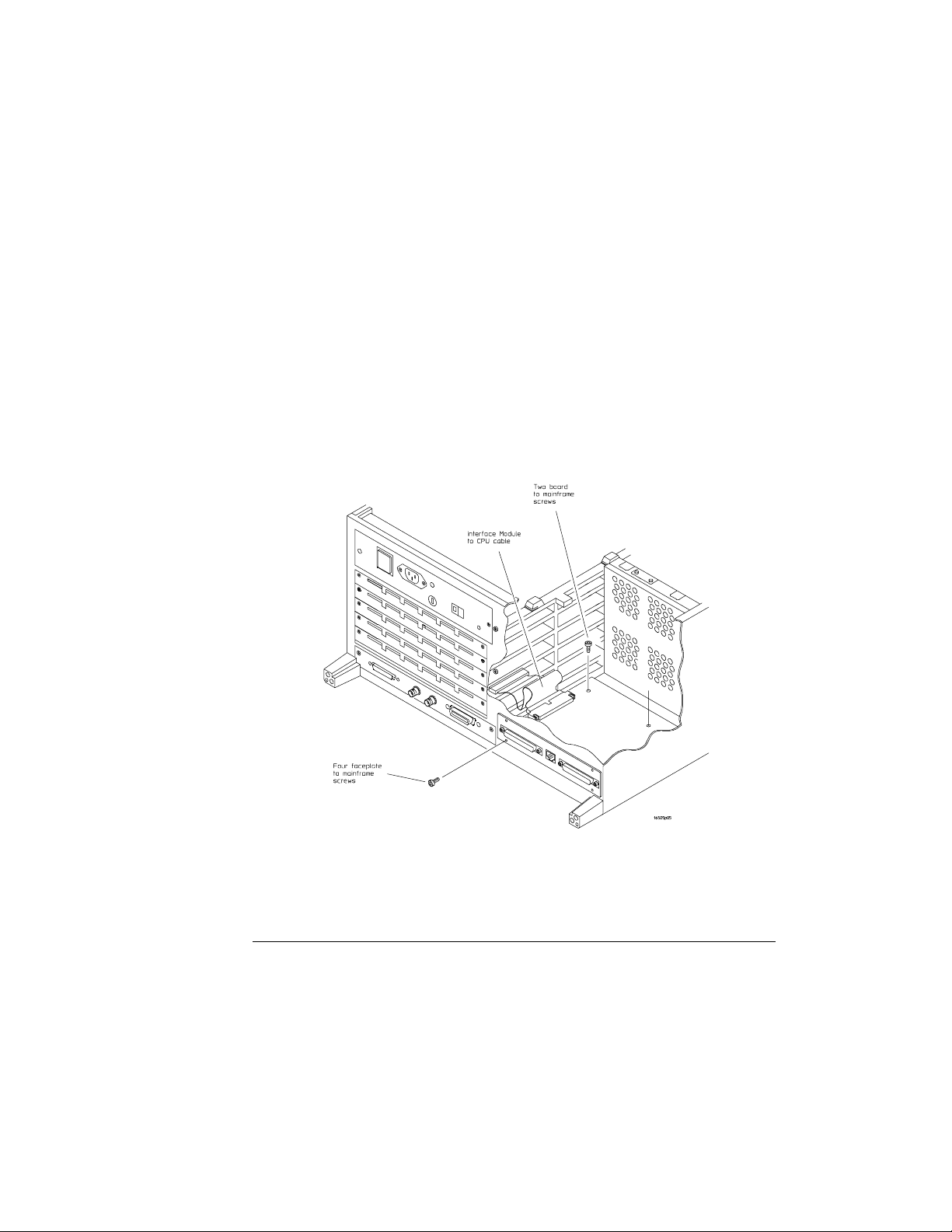
5
Remove the screws connecting the interface module to the
mainframe.
Two screws through the top of the interface module connect it to the
sheetmetal plate, and four screws connect the rear plate of the interface
module to the rear panel of the mainframe (see the figure below).
Removing the Interface Module
3-11
Page 29

Servicing the Interface Module
Removing and Replacing the HP 16500H Interface Module
6
Install the new interface module by reversing this procedure.
7
Test the performance of the interface board.
Refer to "Verifying the interface module performance" in this chapter for the
performance verification test procedure.
8
Reconnect the HP 16505A or HP 16501A to the interface board, or
reconnect the interface board to your network.
If you are reconnecting to a network, refer to the
Service Guide
instructions.
The Ether Address of the replacement interface module will be different than
the other module. At powerup, the HP 16500B operating system reads the
address of the interface module, then records the address in memory.
If your network configuration did not change, the addresses and information
in the configuration menus will remain the same.
, or check with your system administrator for reconnecting
LAN Administartor’s and
3-12
Page 30

CAUTION
Servicing the Interface Module
Returning Parts
Returning Parts
Before shipping the module to Hewlett-Packard, contact your nearest
Hewlett-Packard sales office for additional details.
1
Write the following information on a tag and attach it to the part to
be returned.
Name and address of owner
•
Model number
•
Description of service required or failure indications
•
2
Remove accessories from the module.
Only return accessories to Hewlett-Packard if they are associated with the
failure symptoms.
3
Package the module or assemblies.
You can use either the original shipping containers, or order materials from
an HP sales office.
Package the interface module in electrostatic material. Failure to do so
could cause electrostatic discharge, damaging the module.
4
Seal the shipping container securely, and mark it FRAGILE.
3-13
Page 31

Servicing the Interface Module
Ordering Replaceable Parts
Ordering Replaceable Parts
Parts listed
To order a part on the list of replaceable parts, quote the Hewlett-Packard
part number, indicate the quantity desired, and address the order to the
nearest Hewlett-Packard Sales Office.
Parts not listed
To order a part not on the list of replaceable parts, include the model number
of the module, a description of the part (including its function), and the
number of parts required. Address the order to your nearest
Hewlett-Packard Sales Office.
Direct mail order system
To order using the direct mail order system, contact your nearest
Hewlett-Packard Sales Office.
Within the USA, Hewlett-Packard can supply parts through a direct mail
order system. The advantages to the system are direct ordering and
shipment from the HP Part Center in Mountain View, California. There is no
maximum or minimum on any mail order. (There is a minimum amount for
parts ordered through a local Hewlett-Packard Sales Office when the orders
require billing and invoicing.) Transportation costs are prepaid (there is a
small handling charge for each order) and there are no invoices.
In order for Hewlett-Packard to provide these advantages, a check or money
order must accompany each order. Mail order forms and specific ordering
information are available through your local Hewlett-Packard Sales Office.
Addresses and telephone numbers are located in a separate document at the
back of the HP 16500B Service Guide.
3-14
Page 32

Servicing the Interface Module
Replaceable Parts List
Replaceable Parts List
HP 16500H Interface Module Replacment Parts
Designator HP Part Number QTY Description
A3 16500-66514 1 Interface Board
H2 0515-0372 6 Machine Screw
W1 16500-61613 1 10/40 Cable*
W2 16500-61614 1 Mainframe CPU-Interface Board
Cable
* This cable is only used if the HP 16500H is installed in place of an HP 16500L interface
module.
HP 16500H Replaceable parts
3-15
Page 33

3-16
Page 34

Index
A
accessories,1-3
C
cables
connecting,3-11
orientation,2-2
connections,1-3
D
direct mail order system,3-14
E
echo request,2-5
Ethernet installation,2-5
expansion frame,2-7
F
faulty cable or HP 16500H
performance verification,3-3
H
HP 16501A Expansion Frame,2-7
HP 16505A Prototype Analyzer,2-8
I
installation
expansio n frame,2-7
LAN,2-5
Prototype Analyzer,2-8
verifying,2-4
installing the hardware,2-2 - 2-3
L
LAN installation,2-5
LAN support,1-4
P
parts
ordering,3-14
parts not listed,3-14
returning,3-13
performance verification
failures,3-6
procedure,3-3
self-test description,3-2
ping,2-5
Prototype Analyzer,2-8
R
removing the interface module,3-10 - 3-12
replacing the interface module,3-10 - 3-12
requirements,1-3
returning parts,3-13
S
self-tests
power-up,2-4
T
troubleshooting
HP 16501A Expansion Frame,3-7
in an Ethernet LAN environment,3-8
in the HP 16505A Prototype Analyzer
environment,3-9
U
unmounting from a LAN,3-10
V
verifying the in stallation,2-4
M
mail orders,3-14
Mainframe Test menu,3-5
O
operating requirements,1-3
Option Board Test
accessing,3-5
running, 3-5
ordering parts,3-14
overview,1-2
Index-1
Page 35

Index-2
Page 36

© Copyright HewlettPackard Company 1995
All Rights Reserved.
Reproduction, adaptation, or
translation without prior
written permission is
prohibited, except as allowed
under the copyright laws.
Document Warranty
The information contained in
this document is subject to
change without notice.
Hewlett-Packard makes
no warranty of any kind
with regard to this
material, including, but
not limited to, the implied
warranties of
merchantability or fitness
for a particular purpose.
Hewlett-Packard shall not be
liable for errors contained
herein or for damages in
conne ction with the
furnishing, performance, or
use of th is material.
Safety
This apparatus has been
design ed an d tested in
accordance with IEC
Publication 348, Safety
Requirements for Measuring
Apparatus, and has been
supplied in a safe condition.
This is a Safety Class I
instrument (provided with
terminal for protective
earthing). Before applying
power, verify that the correct
safety precautions are taken
(see the following warnings).
In addition, note the external
markings on the instrument
that are described under
"Safety Symbols."
Warning
Before turning on the
•
instrument, you must connect
the protective earth terminal
of the instrument to th e
protective conductor of the
(mains) power cord. The
mains plug shall only be
inserted in a socket outlet
provided with a protective
earth contact. You must not
negate the protective action
by using an extension cord
(power cable) without a
protective conductor
(grounding). Grounding one
conductor of a two-conductor
outlet is not sufficient
protection.
Only fuses with the
•
required rated current,
voltage, and specified type
(normal blow, time delay,
etc.) should be used. Do not
use repaired fuses or
short-circuited fuseholders.
To do so could cause a shock
of fi re hazard .
Service instructions are for
•
trained service personnel. To
avoid dangerous electric
shock, do not perform any
service unless qualified to do
so. Do not attempt internal
service or adjustment unless
another person, capable of
rendering first aid and
resuscitation, is present.
If you energize this
•
instrument by an auto
transformer (for voltage
reduction), make sure the
common terminal is
connect ed to the earth
terminal of the power source.
Whenever it is likely that
•
the ground p rotection is
impaired, yo u must make the
instrument inoperative and
secure it against any
uninte nded operation.
Do not operate the
•
instrument in the presence of
flammable gasses or fumes.
Operation of any electrical
instrument in such an
environment constitutes a
definite safety hazard.
Do not install substitute
•
parts or perform any
unauthorized modification to
the instrument.
Capacitors inside the
•
instrument may retain a
charge even if the instrument
is disconnected from its
source of supply.
Use caution when exposing
•
or handling the CRT.
Handling or replacing the
CRT shall be done only by
qualified maintenance
personnel.
Safety Symbols
Instruction manual symbol:
the product is marked with
this symbol when it is
necessary for you to refer to
the instruction manual in
order to protect against
damage to the product.
Hazardous voltage symbol.
Earth terminal symbol: Used
to indicate a circuit common
connected to grounded
chassis.
WARNING
The Warning sign denotes a
hazard. It calls attention to a
procedure, practice, or the
like, which, if not correctly
performed or adhered to,
could result in personal
injury. Do not proceed
beyond a Warning sign until
the indicated conditions are
fully understood and met.
CAUTIO N
The Cautio n sign denotes a
hazard. It calls attention to
an operating procedure,
practice, or the like, which, if
not correctly performed or
adhered to, could result in
damage to or destruction of
part or all of the product. Do
not proceed beyond a
Caution symbol until the
indicated conditions are fully
understoo d or met.
Hewlett-Packard
P.O. Box 2197
1900 Garden of the Gods Road
Colorado Springs, CO 80901
Page 37

Product Warranty
This Hewlett-Packard
product has a warranty
against defects in material
and workmanship for a period
of one year from date of
shipment. During the
warranty period,
Hewlett-Packard Company
will, at its option, either
repair or replace products
that prove to be defective.
For warranty service or
repair, this product must be
returned to a service facility
designated by
Hewlett-Packard.
For products returned to
Hewlett-Packard for warranty
service, the Buyer shall
prepay shipping charges to
Hewlett-Packard and
Hewlett-Packard shall pay
shipping charges to return
the product to the Buyer.
However, the Buyer shall pay
all shipping charges, duties,
and taxes fo r products
returned to Hewlett-Packard
from another country.
Hewlett-Packard warrants
that its software and firmware
designated by
Hewlett-Packard for use with
an instrument will execute its
programming instructions
when properly installed on
that instrument.
Hewlett-Packard does not
warrant that the operation of
the instrument software, or
firmware will be
uninterrupted or error free.
Limitation of Warranty
The foregoing warranty shall
not apply to defects resulting
from improper or inadequate
maintenance by the Buyer,
Buyer-supplied software or
interfacing, unauthorized
modification or misuse,
operation o utsid e of the
environmental specifications
for the product, or improper
site preparation or
maintenance.
No other warranty is
expressed or im plied.
Hewlett-Packard
specifically disclaims the
implied warranties of
merchantability or fitness
for a particular purpose.
Exclusive Remedies
The remedies provided herein
are the buyer’s sole and
exclusive remedies.
Hewlett-Packard shall not be
liable for any direct, indirect,
special, incidental, or
consequential damages,
whether based on contract,
tort, or any othe r legal theory.
Assistance
Product maintenance
agreements and other
customer assistance
agreements are available for
Hewlett-Packard products.
For any assistance, contact
your nearest Hewlett-Packard
Sales Office.
Certification
Hewlett-Packard Company
certif ies that this product met
its published specifications at
the time of ship ment from the
factory. Hewlett-Packard
further certifies that its
calibration measurements are
traceable to the United States
National Institute of
Standards and Technology, to
the extent allowed by the
Institute’s calibration facility,
and to the calibration
facilities of other
International Stand ards
Organization members.
About this edition
This is the first editio n of the
HP 16500H Interface
Module Installation and
Service Guide.
Publication number
16500-97012
Printed in USA.
Edition dates are as follows:
First edition, May 1995
New editions are complete
revisions of the manual.
Update packages, which are
issued between editions,
contain additional and
replaceme nt pages to be
merged into the manual by
you. The dates on the title
page change only when a new
edition is published.
A software or firmware code
may be printed before the
date. This code indicates the
version level of the software
or firmware of this product at
the time the manu al or
update was issued. Many
product updates do not
require manual changes; and,
conversely, manual
corrections may be done
without accompanying
product changes. Therefore,
do not expect a one-to-o ne
correspondence between
product updates and manual
updates.
The following list of pages
gives the date of the current
edition and of any changed
pages to that ed ition.
All pages original edition
Page 38

DECLARATION OF CONFORMITY
according to ISO/IEC Guide 22 and EN 45014
Manufacturer’s Name:
Manufacturer’s Address:
Hewlett-Packard Company
Colorado Springs Division
1900 Garden of the Gods Road
Colorado Springs, CO 80907 U.S.A.
declares, that the product
Product Name:
Model Number(s):
Product Option(s):
Prototype Analyzer
HP 16505A/16500H
All
conforms to the following Product Specifications:
Safety: IEC 348:1978 / HD 401 S1:1981
UL 1244
CSA-C22.2 No. 231 (Series M-89)
EMC: CISPR 11:1990 / EN 55011:1991 Group 1 Class A
IEC 801-2:1991 / EN 50082-1:1992 4 kV CD, 8 kV AD
IEC 801-3:1984 / EN 50082-1:1992 3 V/m, {1kHz 80% AM, 27-1000 MHz}
IEC 801-4:1988 / EN 50082-1:1992 0.5 kV Sig. Lines, 1 kV Power Lines
Supplementary Information:
The product herewith complies with the requirements of the Low Voltage
Directive 73/23/EEC and the EMC Directive 89/336/EEC.
Colorado Springs, 9/15/94
European Contact: Your local Hewlett-Packard Sales and Service Office or Hewlett-Packard GmbH, Department ZQ /
Standards Europe, Herrenberger Strasse 130, D-71034 Böblingen Germany (FAX: +49-7031-14-3143)
John Strathman, Quality Manager
 Loading...