

Page 1

Operating Guide
This guide describes how to use the Agilent 53150A, 53151A, and 53152A
Microwave Frequency Counters. The information in this guide applies to
instruments having the number prefix listed below, unless accompanied
by a “Manual Updating Changes” package indicating otherwise.
SERIAL PREFIX NUMBER: 3735A, US3925, and US4050 (53150A)
3736A, US3926, and US4051 (53151A)
3737A, US3927, and US4052 (53152A)
Agilent 53150A/151A/152A
Microwave Frequency Counter
Page 2
Copyright Agilent
Technologies, Inc. 1999, 2002
All Rights Reserved.
Reproduction, adaptation, or
translations without prior
written permission is
prohibited, except as allowed
under the copyright laws.
Printed: August 2002
Printed in U.S.A.
Manual part number
53150-90013
Certification and Warranty
Certification
Agilent Technologies, Inc.
certifies that this product met
its published specification at the
time of shipment from the
factory. Agilent further certifies
that its calibration
measurements are traceable to
the United States National
Institute of Standards and
Technology (formerly National
Bureau of Standards), to the
extent allowed by the Institute’s
calibration facility, and to the
calibration facilities of other
International Standards
Organization members.
Warranty
Agilent warrants Agilent
hardware, accessories and
supplies against defects in
materials and workmanship for
a period of one year from date of
shipment. If Agilent receives
notice of such defects during the
warranty period, Agilent will, at
its option, either repair or
replace products which prove to
be defective. Replacement
products may be either new or
like-new.
Agilent warrants that
Agilent software will not fail to
execute its programming
instructions, for the period
specified above, due to defects in
material and workmanship
when properly installed and
used. If Agilent receives notice
of such defects during the
warranty period, Agilent will
replace software media which
does not execute its
programming instructions due
to such defects.
For detailed warranty
information, see back matter.
Safety Considerations
General
This product and related
documentation must be
reviewed for familiarization
with this safety markings and
instructions before operation.
Before Cleaning
Disconnect the product from
operating power before
cleaning.
Warning Symbols That May
Be Used In This Book
Instruction manual symbol; the
product will be marked with
this symbol when it is necessary
for the user to refer to the
instruction manual.
Indicates hazardous voltages.
Indicates earth (ground)
terminal.
or
Indicates terminal is connected
to chassis when such connection
is not apparent.
Indicates Alternating current.
Indicates Direct current.
Safety Considerations
(cont’d)
WARNING
BODILY INJURY OR DEATH
MAY RESULT FROM
FAILURE TO HEED A
WARNING. DO NOT
PROCEED BEYOND A
WARNING UNTIL THE
INDICATED CONDITIONS
ARE FULLY UNDERSTOOD
AND MET.
CAUTION
Damage to equipment, or
incorrect measurement data,
may result from failure to
heed a caution. Do not
proceed beyond a CAUTION
until the indicated conditions
are fully understood and met.
Safety Earth Ground
An uninterruptible safety earth
ground must be maintained
from the mains power source to
the product’s ground circuitry.
WARNING
WHEN MEASURING POWER
LINE SIGNALS, BE
EXTREMELY CAREFUL AND
ALWAYS USE A
STEP-DOWN ISOLATION
TRANSFORMER WHICH
OUTPUT IS COMPATIBLE
WITH THE INPUT
MEASUREMENT
CAPABILITIES OF THIS
PRODUCT. THIS PRODUCT’S
FRONT AND REAR PANELS
ARE TYPCIALLY AT EARTH
GROUND. THUS, NEVER TRY
TO MEASURE AC POWER
LINE SIGNALS WITHOUT AN
ISOLATION TRANSFORMER.
For additional safety and
acoustic noise information, see
back matter.
Agilent Technologies, Inc. 7.C.NL.06.15.01.R1.M.CW6FC
5301 Stevens Creek Boulevard
Santa Clara, California 95052-8059
Page 3

Contents
Contents and Organization viii
Related Documents ix
Types of Service Available if Instrument Fails x
Repackaging for Shipment xi
Description of the Microwave Frequency Counter xii
Options xiii
Accessories Supplied and Available xiv
Agilent 53150A/151A/152A Quick Reference Guide xv
1 Getting Started
The Front Panel at a Glance 1-2
The Front Panel Indicators at a Glance 1-3
The Front Panel Menus at a Glance 1-4
The Display Annunciators at a Glance 1-5
The Display Special Characters at a Glance 1-6
The Rear Panel at a Glance 1-7
Operating the Counter 1-8
Turning the Counter On 1-10
Turning the Display Backlight Off or On 1-11
Using the Menu 1-12
Displaying the Menu 1-12
Navigating in the Menu and Changing Settings 1-12
Setting the Serial Port Baud Rate (Menu Example) 1-15
Selecting the Input Channel 1-16
Measuring Frequency 1-17
Measuring Relative Frequency 1-19
Offsetting a Frequency Measurement 1-20
Measuring Power (Channel 2 Only) 1-22
Selecting the Unit of Measurement for Power 1-23
Measuring Relative Power 1-24
Offsetting a Power Measurement 1-24
Operating Guide iii
Page 4

Contents
Using Power Correction 1-26
Power Correction Theory of Operation 1-26
Increasing Profile Accuracy 1-27
Selecting a Power-Correction Profile 1-28
Entering Data Points in a Power-Correction Profile 1-28
Setting the Measurement Rate 1-32
Setting the Number of Averages 1-33
Setting the Resolution 1-34
2 Operating Your Frequency Counter
Introduction 2-2
Chapter Summary 2-2
How this Counter Works for You 2-3
Summary of the Measurement Sequence 2-4
Using the Selection Keys 2-5
Sequencing Through the Menu 2-5
Numeric Entry 2-6
Changing States 2-7
Using the Clear and Reset/Local Keys 2-9
Acknowledging Messages 2-9
Other Function Selection Keys 2-10
Measuring Frequency 2-12
Setting the Resolution and the Measurement Rate 2-14
Setting the Resolution 2-14
Resolution Setting Example 2-15
Setting the Measurement Rate 2-16
Rate Setting Example 2-16
Setting the Number of Averages 2-17
Averages Setting Example 2-17
Measuring Relative Frequency 2-20
Relative Frequency Example 2-20
Offsetting a Frequency Measurement 2-21
Frequency Offset Example 2-21
Measuring Power 2-24
Power Measurement Example 2-24
iv Operating Guide
Page 5

Contents
Measuring Relative Power 2-26
Relative Power Example 2-26
Offsetting a Power Measurement 2-27
Power Offset Example 2-27
Using Power Correction 2-30
Power Correction Theory of Operation 2-31
Increasing Profile Accuracy 2-32
Power Correction Examples 2-32
Power Correction Example: Selecting a Correction Profile 2-33
Power Correction Example: Editing Data Point Values 2-35
Using the Menu 2-39
Navigating in the Menu and Changing Settings 2-41
Reference Oscillator (REF OSC)2-42
Do Self Test 2-43
Battery Voltage (BATT VOLTAGE)2-43
Operating Hours (OP HOURS)2-43
Model Number, Firmware Version, Serial Number,
and Option Codes 2-43
Preset 2-45
RS-232 Serial Port Data Rate (BAUD)2-46
Frequency Modulation (FM)2-46
Channel 1 Low-Pass Filter (CH1 LPF)2-46
Recall User Settings (RECALL)2-46
Save User Settings (SAVE)2-46
Power Correction (PWR CORR)2-46
3 Specifications
Introduction 3-2
A Rack Mounting the Counter
Rack Mounting the Counter A-2
Operating Guide v
Page 6

Contents
B Messages
Overview B-2
Status Messages B-2
Self-Test Messages B-3
Error Messages B-4
C Using the Battery Option
Overview C-2
Operating the Counter from the Batteries C-2
Operating the Counter from a DC Power Source C-3
Replacing the Batteries C-4
Removing the Batteries C-4
Installing Batteries C-5
Charging the Batteries C-8
Precautions C-9
vi Operating Guide
Page 7

In This Guide
This book is the operating guide for the Agilent 53150A (20 GHz), 53151A
(26.5 GHz), and 53152A (46 GHz) Frequency Counters. It consists of a
table of contents, this preface, a quick reference guide, three chapters,
three appendices, and an index.
This preface contains the following information:
• Contents and Organization pg. viii
• Related Documents pg. ix
• Types of Service Available if Instrument Fails pg. x
• Repackaging for Shipment pg. xi
• Description of the Microwave Frequency Counter pg. xii
• Options pg. xiii
• Accessories Supplied and Available pg. xiv
• Manuals Supplied pg. xiv
Operating Guide vii
Page 8

In This Guide
Contents and Organization
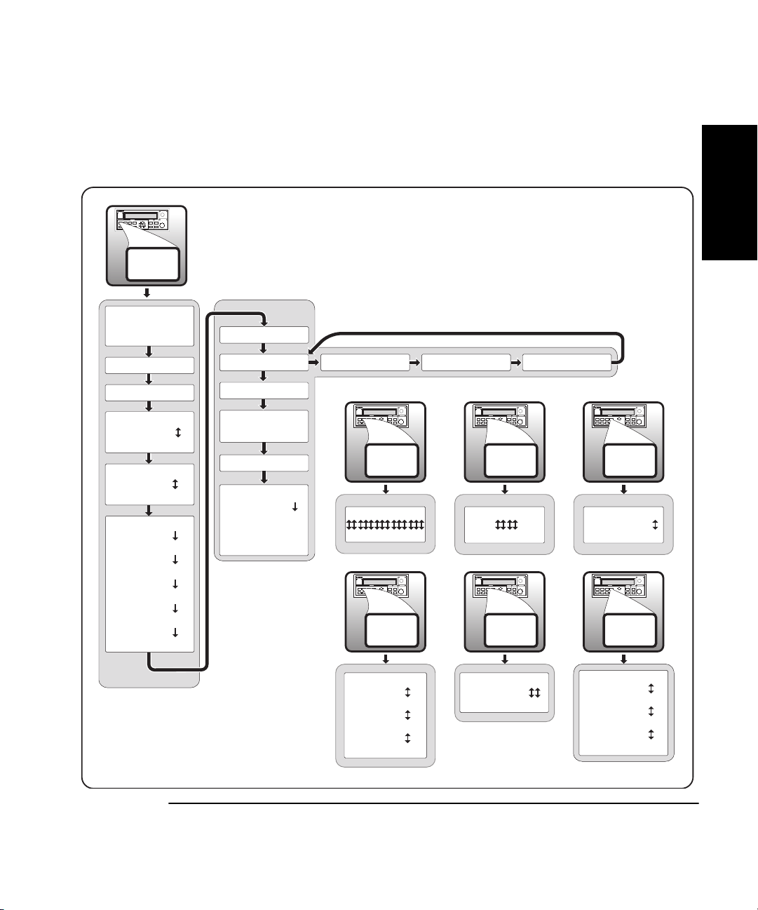
The Quick Reference Guide consists of a Menu Tree (tear-out sheet)
that serves as a tool to trigger your memory or get you quickly
reacquainted with the instrument.
Chapter 1 Getting Started is a quick-start guide that gives you a brief
overview of the Counter’s keys, indicators, menus, display, and
connectors. A graphical procedure for performing a measurement is
also provided.
Chapter 2 Operating Your Instrument is an operator’s reference.
You are given an overview of each group of front-panel keys, operating
functions, and menus followed by a series of exercises that guide you
through the operation of the Counter.
Chapter 3 Specifications lists the specifications and characteristics of
the Counter.
Appendix A Rack Mounting the Counter provides rack-mounting
procedures for the Counter.
Appendix B Messages lists and explains all of the messages that are
displayed on the Counter’s front panel and/or sent over the RS-232
serial interface.
Appendix C Using the Battery Option explains how to use the
Counter with the Battery option.
Index
viii Operating Guide
Page 9

In This Guide
Related Documents
For more information on frequency counters refer to the following Series
200 Application Notes:
• Fundamentals of Electronic Frequency Counters,
Application Note 200—Agilent part number 02-5952-7506.
• Understanding Frequency Counter Specifications,
Application Note 200-4—Agilent part number 02-5952-7522.
• Fundamentals of Time and Frequency Standards,
Application Note 52-1—Agilent part number 02-5952-7870.
Operating Guide ix
Page 10

In This Guide
Types of Service Available if Instrument Fails
If your Counter fails within one year of original purchase, Agilent will
repair it free of charge. If your instrument fails after your one-year
warranty expires, Agilent will repair it, or you can repair it yourself.
There are three types of repair services:
• Standard repair service—if downtime is not critical.
• Express Repair/Performance Calibration Service—if downtime
is critical.
• Owner repair—repair the unit yourself using the Assembly-Level
Service Guide.
Standard Repair Services (Worldwide)
Contact your nearest Agilent Service Center to arrange to have your
Counter repaired.
Express Repair/Performance Calibration Service (USA Only)
If downtime is critical, you can receive your repaired Counter via
overnight shipment. Just call 1-800-403-0801 and ask for Express
Repair/Performance Calibration Service. When your Counter is repaired,
it will be returned via overnight shipment.
Repair Instrument Yourself
If you choose to repair the instrument yourself or would like more details
on self test and calibration, use the procedures in the Assembly-Level
Service Guide.
x Operating Guide
Page 11

In This Guide
Repackaging for Shipment
For the Express Repair/Performance Calibration Service described above,
return your failed Counter to the designated Agilent Service Center,
using the instrument’s original shipping carton (if available). Agilent
notifies you when your failed instrument is received.
If the instrument is to be shipped to Agilent for service or repair, be sure
you do the following:
• Attach a tag to the instrument identifying the owner and indicating
the required service or repair. Include the instrument model number
and full serial number.
• Place the instrument in its original container (if available) with
appropriate packaging material.
• Secure the container with strong tape or shipping bands.
If the original shipping container is not available, place your unit in a
container with at least 4 inches of compressible packaging material
around all sides of the unit. Use static free packaging materials to avoid
additional damage to your unit.
Agilent suggests that you always insure shipments.
Operating Guide xi
Page 12

In This Guide
Description of the Microwave Frequency Counter
The Agilent 53150A, 53151A, and 53152A Microwave Frequency Counters
are capable of measuring frequencies from 10 Hz to 125 MHz on Channel 1
and from 50 MHz to 20 GHz (53150A), 26.5 GHz (53151A), and 46 GHz
(53152A) on Channel 2. These frequency counters are also capable of
measuring power on Channel 2 (in the same frequency ranges). All three
Counters have a maximum frequency resolution of 1 Hz.
The Agilent 53150A/151A/152A provides GPIB and RS-232 serial
interfaces and are suitable for bench-top and ATE operation.
The basic measurement functions of the Agilent 53150A/151A/152A
include Frequency, Relative Frequency, Frequency Offset, and Power
(including Power Offset and Relative Power). All of these features are
accessible from the front panel and over the GPIB and RS-232 interfaces.
The Agilent 53150A/151A/152A includes the following additional
measurement functions and features that are designed specifically for
manufacturing and service applications:
• 1, 2, 5, and 10 MHz external reference capability
• Optional high-stability oven oscillator for high-accuracy needs and
lengthened calibration cycles
• Frequency and power offset capabilities for relative measurements
• SCPI programming capability
• Battery and dc input option for operation in locations where AC
power is unavailable
• Optional soft carrying case for safe transportation and mobile use
Programmable control is performed via an GPIB or an RS-232 serial
interface. The GPIB and RS-232C ports are standard for the Agilent
53150A, 53151A, and 53152A.
xii Operating Guide
Page 13

In This Guide
Options
The options available for the Agilent 53150A/151A/152A are listed below.
Specifications for the options are listed in Chapter 3, “Specifications.”
Options ordered with the Counter are installed at the factory and are
ready for operation on delivery. Refer to the "Retrofitting Options" chapter
in the Agilent 53150A/151A/152A Assembly-Level Service Guide for
information on installing options in the field.
Hardware
• High Stability Oven Timebase, Option 001
• Battery/DC Power Input, Option 002
• Rack Mount Kit, Option 1CM
• Soft Carrying Case, Option 007
Support
• 3-year Return to Agilent for Repair, Option W30
• 3-year Return to Agilent for Calibration, Option W32
• 3-year Return to Agilent for Standards Compliant Calibration,
Option W34
• 5-year Return to Agilent for Repair, Option W50
• 5-year Return to Agilent for Calibration, Option W52
• 5-year Return to Agilent for Standards Compliant Calibration,
Option W54
Retrofit
• Options 001 and 002 can be installed only by authorized Agilent
Technologies Repair Centers.
Operating Guide xiii
Page 14

In This Guide
Accessories Supplied and Available
Accessories Supplied
• Power cord, 2.3 meters (Part number dependent upon destination country)
• Fuse (Agilent P/N 2110-0007)
Accessories Available
• Soft Carrying Case, (Agilent P/N 53150-80016)
• Automotive Power Adapter (Agilent P/N 53150-60214)
• Battery (Agilent P/N 53150-80010)
• GPIB Cables (Agilent P/N 10833A/B/C/D)
• RS-232 Cable (Agilent P/N 53150-60215)
Manuals Supplied
Agilent 53150A/151A/152A Operating Guide
(Agilent P/N 53150-90013)
Agilent 53150A/151A/152A Programming Guide
(Agilent P/N 53150-90014)
Agilent 53150A/151A/152A Assembly-Level Service Guide
(Agilent P/N 53150-90015)
xiv Operating Guide
Page 15

Agilent 53150A/151A/152A
Quick Reference Guide
The Quick Reference Guide is designed for experienced
users of the Agilent 53150A, 53151A, and 53152A. It is
intended to be used as a tool to trigger your memory.
If you are using the Counter for the first time, Agilent
recommends that you at least read Chapter 1, “Getting
Started,” first.
The Quick Reference Guide, which follows this page,
consists of a menu tree that may be torn out of the guide
for external use.
Reference
Quick
xv
Page 16

Quick
Reference
xvi
Page 17
A
A
gilent 53150A/151A/152
Frequency Counter
On/Off
+/-Clear
Menu
Reset/
Local
REF OSC > INT
REF OSC > EXT
PRESET
Reference
Reference
Quick
Quick
SAVE > 0 to 9
RECALL > 0 to 9
CH1 LPF > OFF
CH1 LPF > ON
FM > AUTO
FM > OFF
BAUD > 9600
BAUD > 4800
BAUD > 2400
BAUD > 1200
BAUD > 19200
BAUD > 14400
53150A >
OP 9999 HRS
BATT VOLTAGE
0.0
DO SELF TEST
PWR CORR > OFF
PWR CORR > 0
to
PWR CORR > 9
< 00-111-222 >
Freq
Offset
Rate
00 000 000 000 000
49 999 999 999 999 ± 99.99
Freq
Offset
Rate
RATE FAST
RATE MED
< SN 999999 >
AVERAGES 01
AVERAGES 99
RATE SLOW
RATE HOLD
<OPTNS -- -- -- -- >
Pwr
Offset
Avg
± 00.00
Pwr
Offset
Avg
GPIB
Resol
± 00.00
GPIB ADDR > 0
GPIB ADDR > 30
GPIB
Resol
RESOL 1 HZ
RESOL 10 KHZ
RESOL 100 KHZ
RESOL 1 MHZ
QR-1
Page 18

Quick
Reference
QR-2
Page 19

1
Getting Started
Page 20
1342
Chapter 1 Getting Started
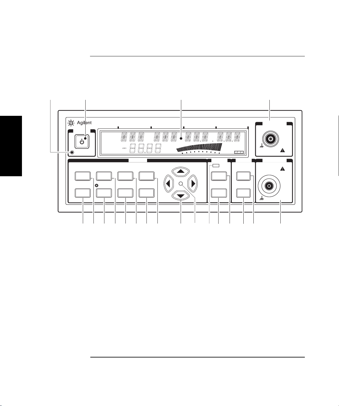
The Front Panel at a Glance
The Front Panel at a Glance
53150A
POWER
1
Standby
Menu
Reset/
Local
Shift
Freq
Offset
Rate
On/Off
Clear
Ch 12
Rel Freq
Offset
Avg On
Rel Pwr
Offset
GHz MHz
MODIFY
Pwr
Offset
Avg
+/-
GPIB
Resol
Enter
dB
dBm
Watts
mW
uW
%
kHz Hz
20
1 Standby indicator
2 Power/Standby switch
3 LCD display
4 Channel 1 input connector
5 Channel 2 input connector
6 Display Power / dBm/W key (Channel 2)
7 Offset On/Off / Relative Power key
(Channel 2)
Channel Selection key
8
9 Offset On/Off / Relative Frequency key
11 Selection keys active indicator
12 Selection (arrow) keys
13 Resolution / GPIB key
14 Enter key
15 Average / Power Offset key
16 Sign (+/–) key
17 Rate / Frequency Offset key
18 Clear / Backlight On/Off key
19 Reset/Local / Menu key
20 Shift key
20 GHz Counter
Ext Rel
Hold
Rate Rmt SRQ
Error
Shift
FREQ
Chan
Select
Rel Freq Rel Pwr
Offset
On/Off
Gate
Channel 2
dBm/ W
Display
Power
Offset
On/Off
CHANNEL 1
10 Hz to 125 MHz
1M Ω
DAMAGE
+30 dBm
CHANNEL 2POWER
50 MHz to 20 GHz
DAMAGE
+27 dBm
5678912 1013 11141516171819
50 Ω
10 Gate indicator
1-2 Operating Guide
Page 21
Chapter 1 Getting Started
The Front Panel Indicators at a Glance
The Front Panel Indicators at a Glance
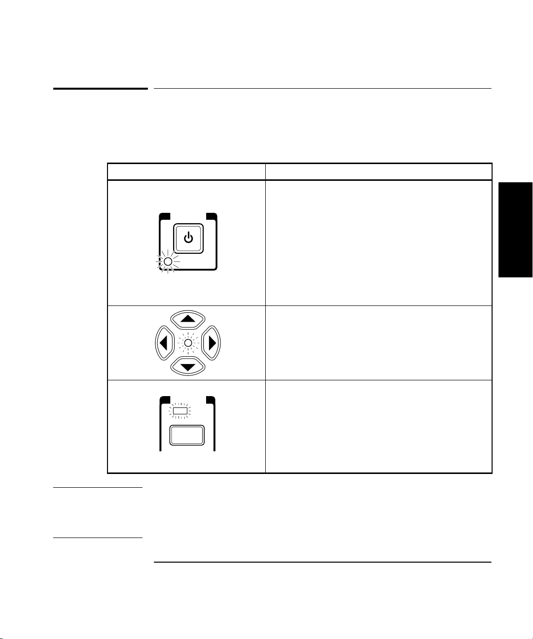
The front panel includes three LED indicators. These are listed and
described in the following table.
Indicator Description
The Standby indicator is lit whenever the Main ~
Power switch on the rear panel is turned ON, and
POWER
Standby
the POWER switch on the front panel is OFF (out).
During Standby, most of the instrument’s circuits do
not receive power. However, the timebase and the
cooling fan are powered so that the temperature in
the timebase components remains stable, and if the
Battery option is installed, the battery-charging
circuits are powered. When you press the POWER
switch on the front panel, the Standby indicator goes
off, and all of the Counter’s circuits receive power.
1
When the LED indicator between the arrow keys
flashes, the arrow keys can be used to navigate and
change values in menus.
When you make a change in a menu, always press
the Enter key to save the setting and exit the menu.
The Gate LED indicator flashes to indicate the rate
FREQ
Chan
Select
Gate
at which measurements are triggered. The flash rate
of the LED varies with the settings of the
measurement rate (Rate key) and the measurement
resolution (Resol key). The flash rate of the LED
provides a rough indication of the number of
measurements that are being taken in a given period
of time.
NOTE It is normal for the fan in the Counter to run when the Counter is in
Standby mode. Power is supplied to the timebase whenever the
Main ~ Power switch is on to maintain long term measurement reliability,
and the fan helps maintain timebase temperature stability.
Operating Guide 1-3
Page 22
Chapter 1 Getting Started
The Front Panel Menus at a Glance
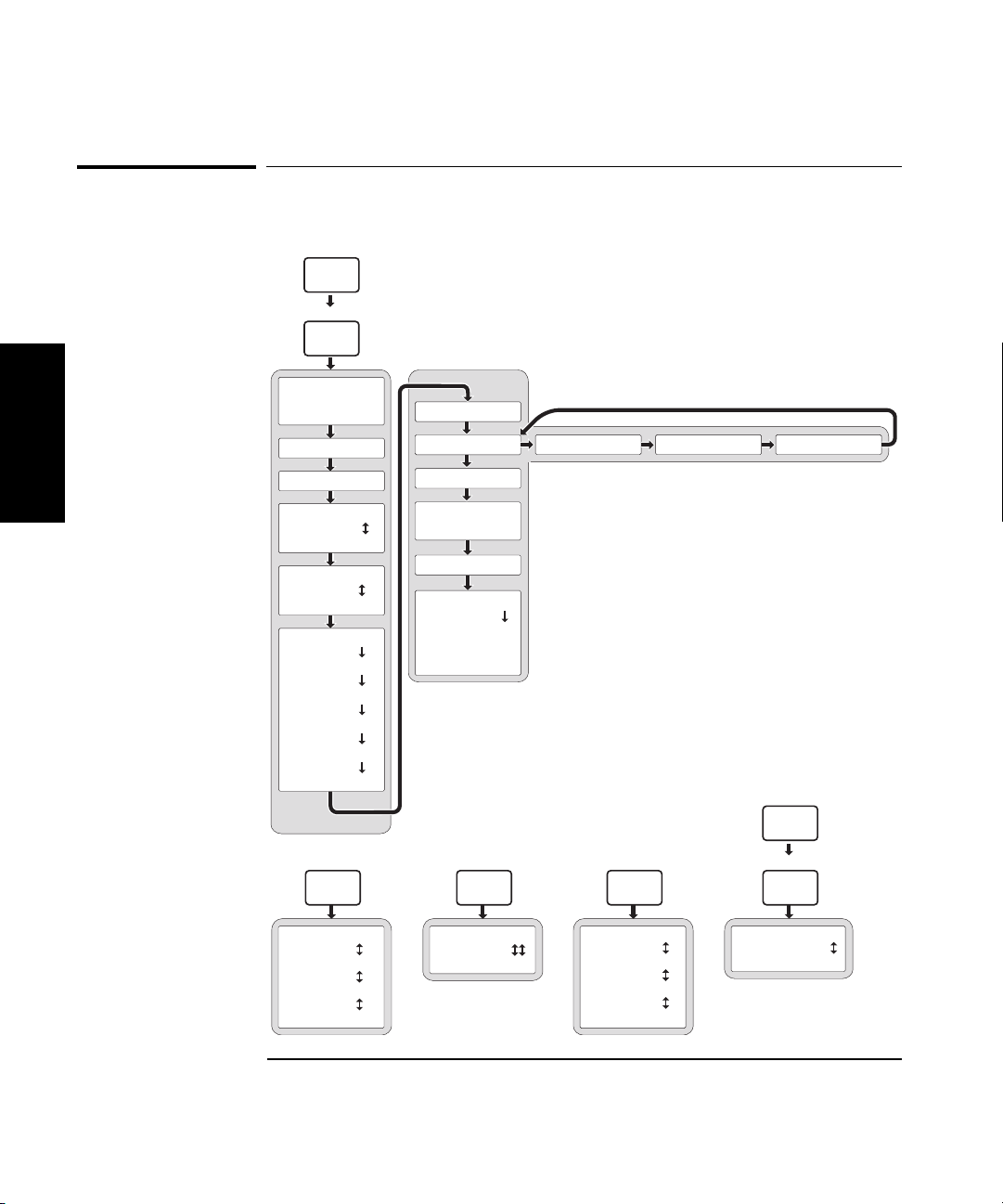
The Front Panel Menus at a Glance
Shift
Menu
Reset/
Local
REF OSC > INT
1
SAVE > 0 to 9
RECALL > 0 to 9
REF OSC > EXT
PRESET
53150A >
OP 9999 HRS
< 00-111-222 >
< SN 999999 >
<OPTNS -- -- -- -- >
CH1 LPF > OFF
CH1 LPF > ON
FM > AUTO
FM > OFF
BAUD > 9600
BAUD > 4800
BAUD > 2400
BAUD > 1200
BAUD > 19200
BAUD > 14400
Rate
RATE FAST
RATE MED
RATE SLOW
RATE HOLD
BATT VOLTAGE
0.0
DO SELF TEST
PWR CORR > OFF
PWR CORR > 0
to
PWR CORR > 9
Avg
AVERAGES 01
AVERAGES 99
Resol
RESOL 1 HZ
RESOL 10 KHZ
RESOL 100 KHZ
RESOL 1 MHZ
Shift
GPIB
Resol
GPIB ADDR 0
GPIB ADDR 30
1-4 Operating Guide
Page 23
Chapter 1 Getting Started
The Display Annunciators at a Glance
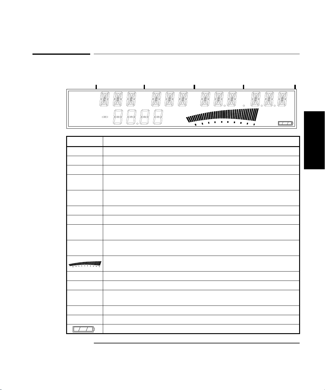
The Display Annunciators at a Glance
GHz
MHz
kHz
Hz
Ch 12
Rel Freq
Offset
Avg On
Rel Pwr
Offset
dB
dBm
Watts
mW
uW
%
Annunciator Description
Ch 1 or Ch 2 Indicates which channel is selected to measure an input signal.
Freq Indicates that the value displayed is a frequency reading.
Rel Freq The displayed frequency value is relative to a previously zeroed value.
Freq
The displayed frequency value is offset by a previously entered frequency value.
Offset
Avg On The displayed frequency value is the result of a number of individual frequency
measurements that have been averaged.
Pwr The Counter is set to measure Power (Channel 2 only).
Rel Pwr The displayed power measurement is relative to a previously zeroed power value.
Pwr
The displayed power value is offset by a previously entered power value.
Offset
dB, dBm, W,
µW, %
mW,
Indicates the unit of measurement for the currently displayed power value.
Provides a real-time analog representation of the Power measurement (intended for
peaking and similar procedures).
Ext Ref The Counter is using an external reference signal for frequency measurements.
Hold Indicates the Counter is in Hold (single-measurement) mode.
Rmt, SRQ Shows the current state of the GPIB interface
(Rmt = Remote operation via GPIB; SRQ = Service ReQuest).
Error Indicates that a front-panel key command is unacceptable in the current context.
Shift Indicates that all front-panel keys are redefined to the function printed above the key.
Shows the amount of charge in the batteries (if the Battery option is installed).
Ext Rel
Hold
Rate Rmt SRQ
Error
Shift
1
Operating Guide 1-5
Page 24
Chapter 1 Getting Started
The Display Special Characters at a Glance
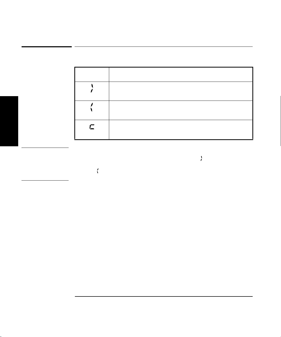
The Display Special Characters at a Glance
Special
Characters
1
NOTE The first two special characters shown above are intended to help you
navigate within the Menu. When the right pointer ( ) is flashing, it
indicates the current setting for the selected Menu option. When the left
pointer ( ) is flashing, it indicates that you can use the selection (arrow)
keys to change the setting for the current Menu option.
Description
Points to the current value for a Menu setting.
Indicates that the value for the current Menu setting can be
changed using the selection (arrow) keys.
When the letter “c” is displayed in the hundredths position of
the power display, Power Correction mode is in effect.
1-6 Operating Guide
Page 25
Chapter 1 Getting Started
The Rear Panel at a Glance
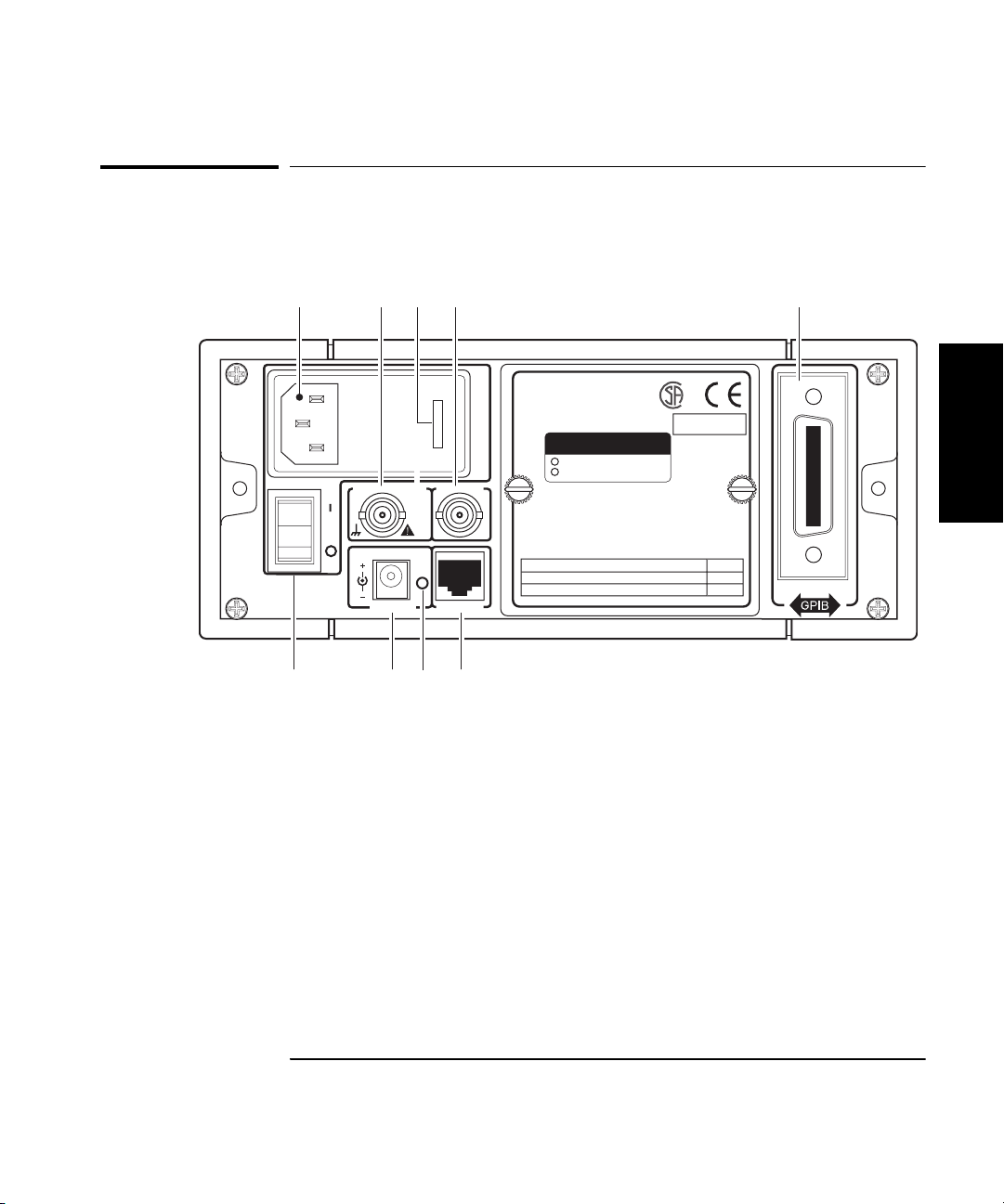
The Rear Panel at a Glance
1
Main ~ Power
10 9 7
2 43 6
Reference 10 MHz
11 TO 18 VDC
EXT DC
Auxillary
In
or
Out
RS-232
8
1 AC Input/Power module (Senses
incoming voltage and adjusts
automatically)
2 External Reference connector (BNC)
1, 2, 5, or 10 MHz Input
10 MHz Output
3 Fuse Holder (behind door)
4 Auxiliary connector (reserved)*
5
Made in U.S.A.
with domestic and foreign content
OPTIONS
001 Oven Time Base
002 Battery
WARNING:
To avold electric shock,
do not remove covers.
No user-serviceable parts inside.
Refer all servicing to qualified personnel.
This unit must be earth grounded.
AC POWER
100 – 130 VAC, 50/60/400 Hz 75 VA
220 – 240 VAC, 50/60 Hz 75 VA 250 V
5 Battery compartment (optional) or cover plate
6 GPIB (IEEE-488.1) Interface connector
7 RS-232 Interface connector (RJ12)
8 Main AC Power On indicator
9 EXT DC power-input connector (functional only
when Battery option is installed)
10 Main ~ Power switch
ISM 1-A
FUSE
1.0 A T
1
* The Auxiliary connector is not installed on standard production units.
Operating Guide 1-7
Page 26

Chapter 1 Getting Started
Operating the Counter
Operating the Counter
The procedures in this section are designed to familiarize you with the
Frequency Counter’s features and controls. Agilent suggests that you
follow the steps for each of these procedures, even if you do not presently
need to make any measurements or to adjust any of the Counter’s settings.
The following procedures are provided:
• Turning the Counter On
• Turning the Display Backlight Off or On
1
• Selecting an Input Channel
• Using the Menu
• Setting the Serial Port Baud Rate
• Measuring Frequency
• Measuring Relative Frequency
• Offsetting a Frequency Measurement
• Measuring Power
• Measuring Relative Power
• Offsetting a Power Measurement
• Using Power Correction
• Setting the Measurement Rate
• Setting the Number of Averages
• Setting the Resolution
1-8 Operating Guide
Page 27
Chapter 1 Getting Started
Operating the Counter
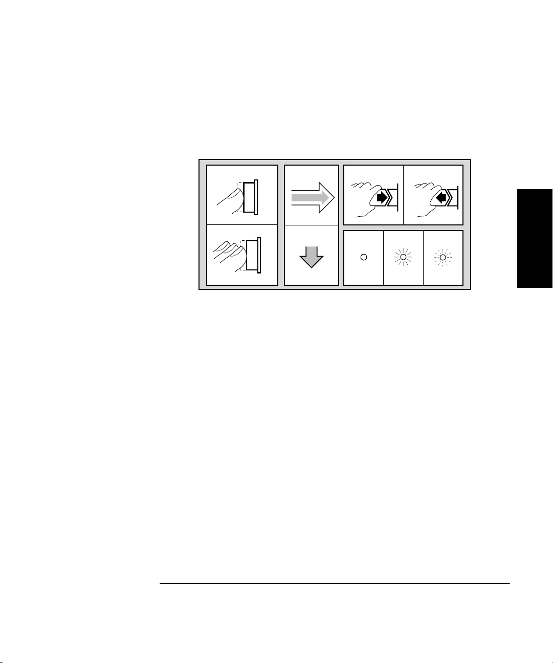
The following legend defines the meanings of the icons used throughout
this chapter.
Legend
1
2
1 Press key one
time and release
2 Multiple key
presses
3
4
3 Result
4 Auto operation
5 Connect signal
6 Disconnect signal
56
798
1
7 Indicator off
8 Indicator on
9 Indicator flashing
Operating Guide 1-9
Page 28
Chapter 1 Getting Started
Operating the Counter
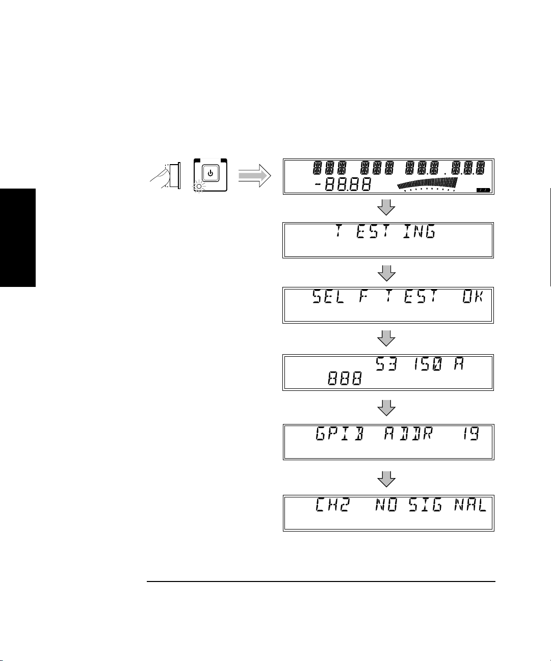
Turning the Counter On
To turn on the Counter, turn on the Main ~ Power switch on the rear panel
(see page 1-7), and then press and release the POWER button on the
front panel.
POWER
Standby
Ch 12
Rel Freq
Offset
Avg On
Rel Pwr
Offset
Ext Rel
dB
dBm
Watts
mW
uW
%
Hold
Rate Rmt SRQ
Error
Shift
1
Ch 2
Freq
1-10 Operating Guide
Page 29
Chapter 1 Getting Started
Operating the Counter
NOTE If a signal was applied to the Channel 2 input connector prior to turning
on the Counter, CH2 NO SIGNAL is displayed momentarily. As soon as the
Counter acquires the input signal, it displays the signal’s value.
NOTE The internal Reference Oscillator requires 10 to 15 minutes to reach a
stable operating temperature. Since the Reference Oscillator receives
power only when the Counter is on or in Standby mode, no measurements
should be taken unless the Counter’s Main ~ Power switch has been in the
on (1) position for at least that amount of time.
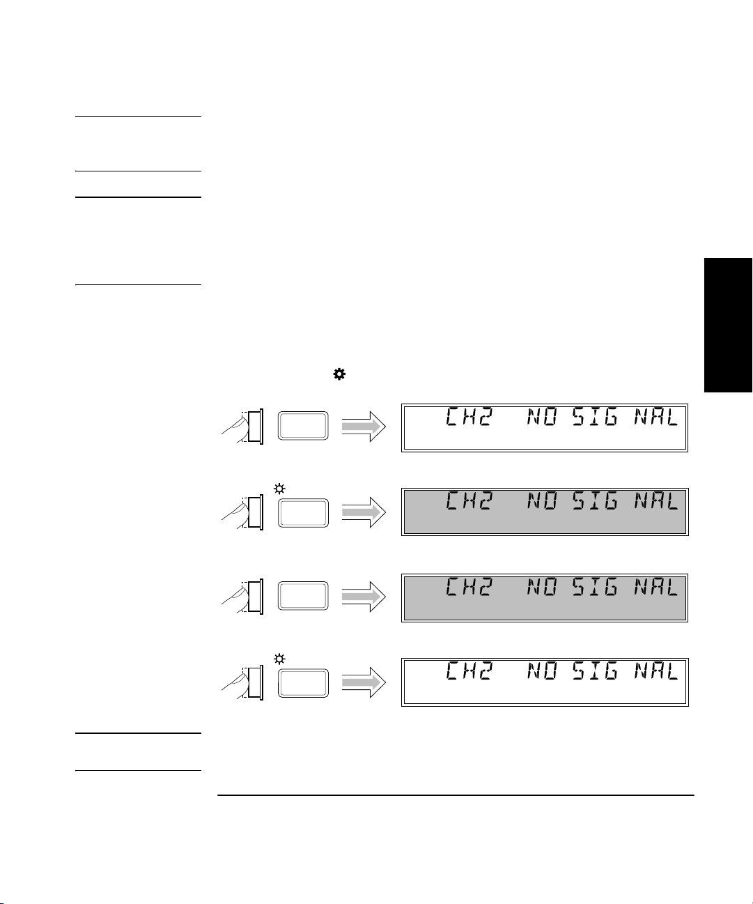
Turning the Display Backlight Off or On
When you first turn the Counter on, the backlight for the LCD display is
always lit. You can toggle the backlight off and on by pressing the Shift
key and then the On/Off (Clear) key, as shown below.
Ch 2
Shift
On/Off
Clear
Shift
On/Off
Clear
Freq
Ch 2
Freq
Ch 2
Freq
Ch 2
Freq
Shift
Shift
1
NOTE If your Counter has the Battery option, you can extend the length of time the
Counter can operate from the batteries by turning off the display backlight.
Operating Guide 1-11
Page 30

Chapter 1 Getting Started
Operating the Counter
Using the Menu
The Agilent 53150A/151A/152A Counter has one menu that you use to
control a number of the Counter’s features and functions.
Displaying the Menu
To display the Menu, press the Shift key and then the Menu (Reset/Local)
key, as shown below.
Ch 2
Shift
Freq
1
Menu
Reset/
Local
Navigating in the Menu and Changing Settings
Use the Selection (arrow) keys to navigate to the setting you want to
change and then to actually make the changes. For example, the diagram
on the next page shows how to change the setting of the Reference
Oscillator from INTernal to EXTernal. (In this example, a reference signal
is applied to the External Reference connector, but no signal is applied to
the Channel 2 input.)
NOTE The Counter will not switch to EXTernal unless a suitable reference
signal is available at the External Reference connector.
Shift
1-12 Operating Guide
Page 31

Chapter 1 Getting Started
Operating the Counter
Shift
Menu
Reset/
Local
Ch 2
Freq
Shift
1
Enter
Ch 2
Ext Ref
When you select the Menu, the indicator between the arrow keys flashes
to indicate that the arrow keys are now active. Since the Reference
Oscillator setting is the first one displayed when you invoke the Menu
(unless you’ve used the Menu to change another setting since you turned
the Counter on), you don’t have to use the (up-arrow) key or the
(down-arrow) key to get to it.
Operating Guide 1-13
Page 32

Chapter 1 Getting Started
Operating the Counter
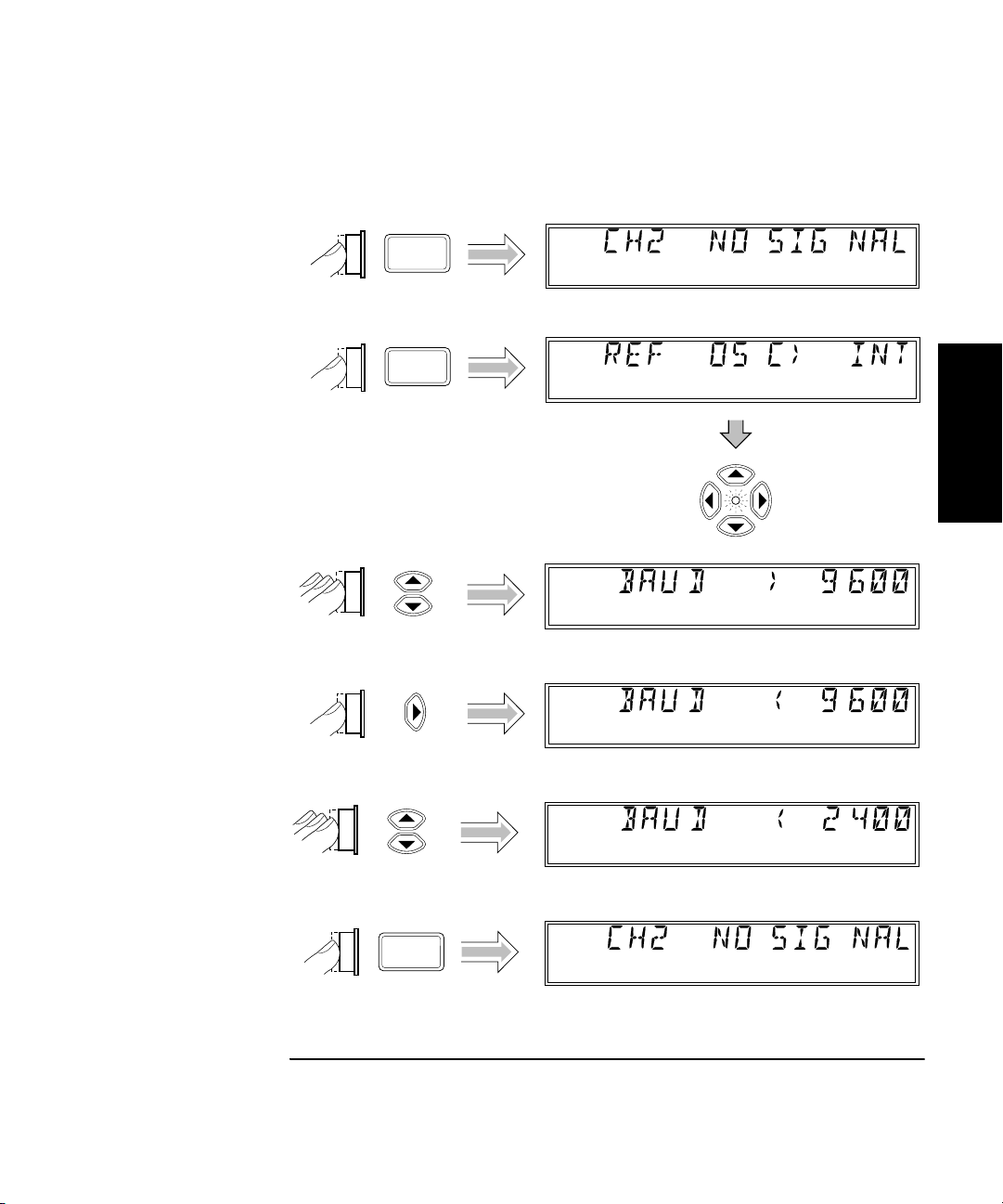
When you press the (right-arrow) key, the flashing annunciator ( )
changes direction, and the current setting for the Reference Oscillator
(INT [internal] or EXT [external]) flashes. This indicates that you can now
change this setting. Use either the up-arrow key or the down-arrow key to
change the setting.
If there are more than two settings available for the currently selected
function, you can cycle through the available settings by repeatedly
pressing either the up-arrow key or the down-arrow key. For example, to
change the setting for the Baud rate for the serial port, use the sequence
on the next page.
1
Press either the Enter key or the left arrow key to accept the currently
displayed setting. The Enter key accepts the setting and exits the Menu;
the left arrow key accepts the setting but does not exit the Menu. Use the
left arrow key to accept a setting if you want to change additional menu
settings. The Clear key reverses an unaccepted setting change.
You navigate to and adjust the remaining settings available in the Menu
in the manner described above. The Menu also contains some items that
provide information only (no settings are required [or possible] for these),
such as Battery Voltage, Operation Hours, and information that identifies
the Counter (Agilent model number, firmware version number, serial
number, and installed option codes). These menu options and the ones
described below are shown in “The Front Panel Menus at a Glance” on
page 1-4.
There is also a menu item called Preset and one called Do Self Test. If you
press the Enter key while PRESET is displayed, all of the Counter’s
settings are returned to the factory-default settings. If you press Enter
while DO SELF TEST is displayed, the Counter repeats the tests that are
normally performed when the Counter is first turned on.
NOTE Remember to terminate each value you change in any of the menu options
by pressing the
Enter key or the left arrow key. You can abort a change to
any menu option while the Menu is displayed by pressing the
key or the
Clear key. Both keys nullify any changes you made to the
current menu option, but they do not affect any changes to other menu
options. The
Reset/Local key does not.
Clear key terminates the current menu session, but the
Reset/Local
1-14 Operating Guide
Page 33
Chapter 1 Getting Started
Operating the Counter
Setting the Serial Port Baud Rate (Menu Example)
Ch 2
Shift
Menu
Reset/
Local
Freq
Shift
1
Ch 2
Enter
Freq
Operating Guide 1-15
Page 34

Chapter 1 Getting Started
Operating the Counter
Selecting the Input Channel
You can toggle between Channels 1 and 2 by pressing the Chan Select key.
Ch 1
Chan
Select
Chan
Select
Freq
Ch 2
Freq
1
1-16 Operating Guide
Page 35
Chapter 1 Getting Started
Operating the Counter
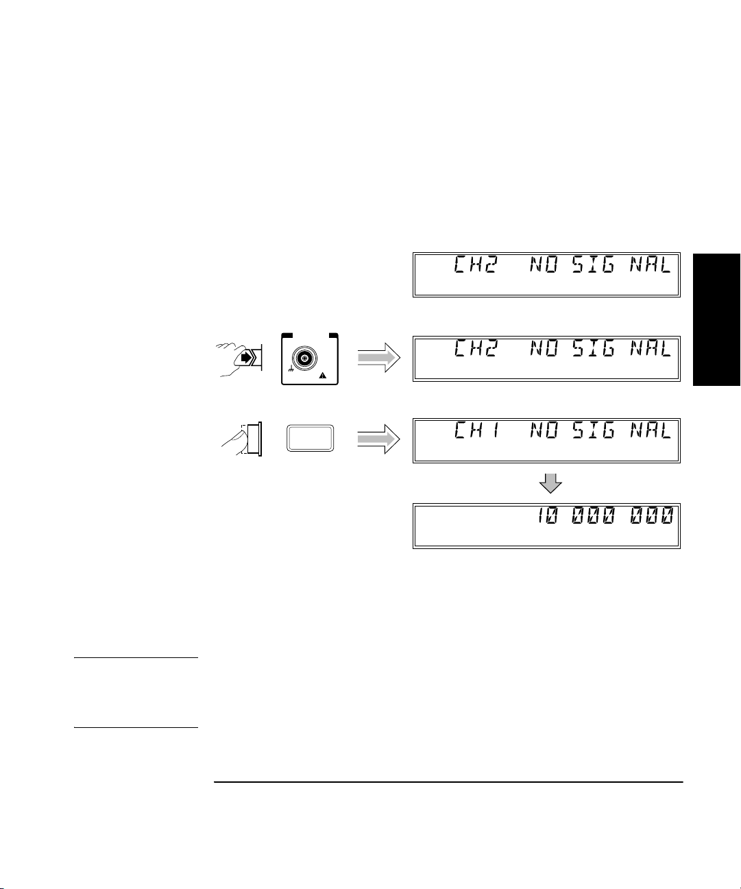
Measuring Frequency
The following diagram shows the basic sequence to use to make a
frequency measurement using Channel 1. This example assumes that the
Counter is on and has completed the Self Test. For the purposes of this
example, use the 10 MHz reference output on the Counter’s rear panel as
a signal source for input to Channel 1.
Ch 2
Freq
CHANNEL 1
10 Hz to 125 MHz
DAMAGE
+30 dBm
Chan
Select
1M!Ω
Ch 2
Freq
Ch 1
Freq
1
Ch 1
Freq
The same procedure applies to making a basic frequency measurement on
Channel 2. However, since Channel 2 is automatically selected when you
turn on the Counter, the channel-selection step is unnecessary (unless you
previously selected Channel 1).
CAUTION The Channel 2 input path circuits contain sensitive GaAs semiconductors.
To prevent damage to these components, always adhere to standard ESD
(Electro-Static Discharge) prevention procedures, and ensure that the
maximum power specification for this channel (+27 dBm) is not exceeded.
Operating Guide 1-17
Page 36

Chapter 1 Getting Started
Operating the Counter
NOTES The Counter displays CH2 NO SIGNAL or CH1 NO SIGNAL and shuts
down all unnecessary circuits when a signal of insufficient amplitude
(or no signal) is applied to the corresponding input. This extends the
reliability of the affected components, and if the Battery option is
installed, extends the length of time the Counter can operate from
the batteries.
When the frequency of a signal applied to the Channel 2 input exceeds the
maximum rated frequency for the instrument, the Counter displays CH2
TOO HIGH.
1
CAUTION The 2.9 mm Planar Crown* connector used for the Channel 2 input on the
Agilent 53152A must be handled with care to prevent damage and/or
contamination, especially since it acts as a wave guide as well as an
electrical connection. Observe the following precautions when handling
this connector:
1. If you remove the outer portion of the connector, do not touch the
exposed surfaces of either part of the connector with your bare skin or
any material that is not intended for cleaning this type of connector.
2. Avoid dropping or striking either portion of the connector.
If the connector becomes contaminated, it can be cleaned with isopropyl
alcohol and a lint-free cloth or other suitable cleaning implement.
* Planar Crown® is a registered trademark of Weinschel Corp.
1-18 Operating Guide
Page 37
Chapter 1 Getting Started
Offset
On/Off
Operating the Counter
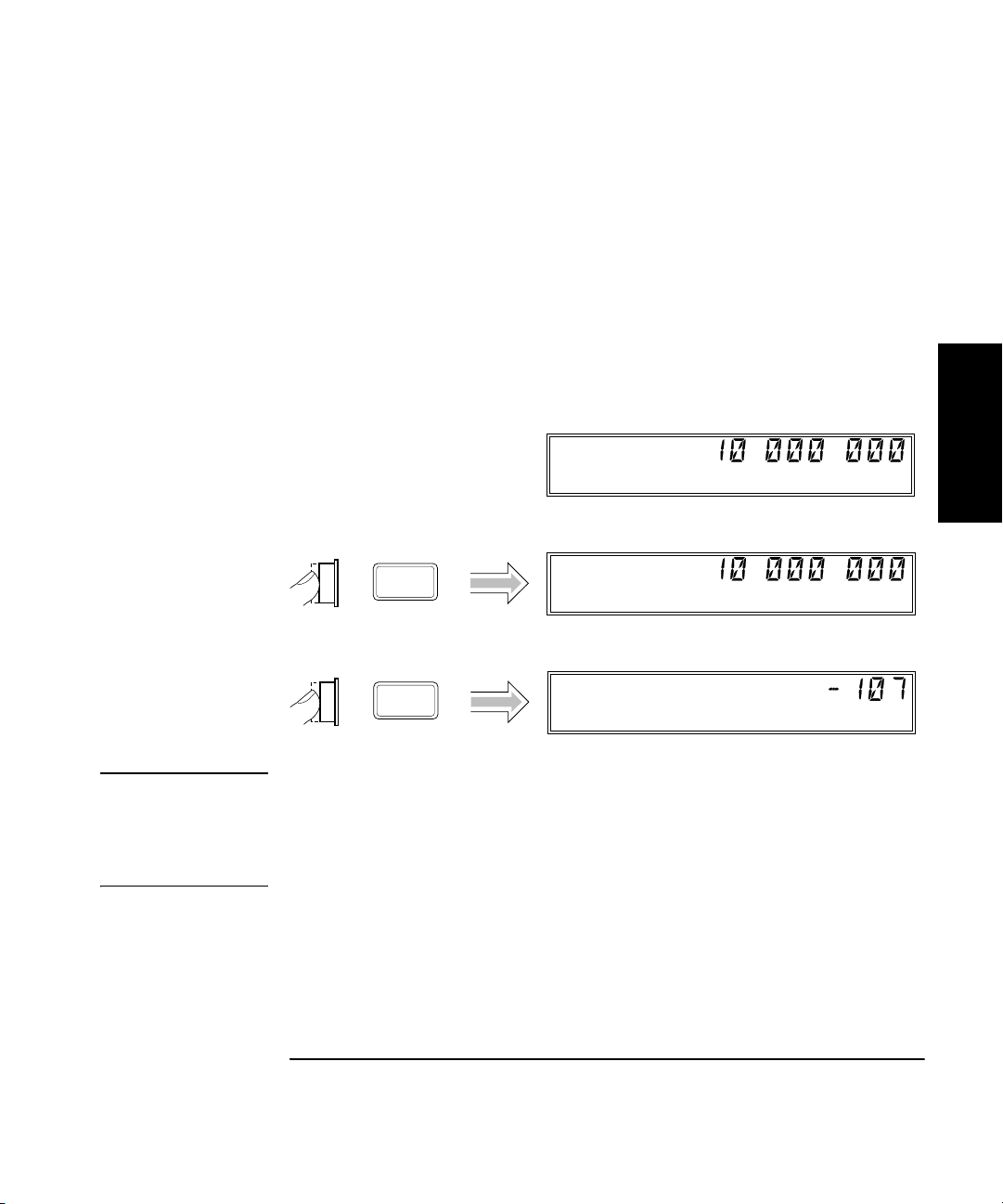
Measuring Relative Frequency
You can measure the difference in frequency from one measurement to
another (drift) using the Relative Frequency function. You do this by
pressing the Shift and Rel Freq (Offset On/Off) keys as shown in the
diagram below (this example assumes that a signal is currently applied
to Channel 1).
The Counter stores the current frequency reading when you press the
Rel Freq key. It then subtracts this value from all subsequent readings
and displays the difference until you press the Rel Freq key again.
Ch 1
Freq
Ch 1
Shift
Freq
Shift
1
Rel Freq
Offset
On/Off
Ch 1
Rel Freq
NOTE If the input signal fluctuates, the value displayed varies as the Counter
continues to take measurements. You can vary the speed at which
measurements are taken by varying the settings for Rate and Resolution
(see “Setting the Measurement Rate” and “Setting the Resolution” on
pages 1-32 and 1-34).
Operating Guide 1-19
Page 38

Chapter 1 Getting Started
Operating the Counter
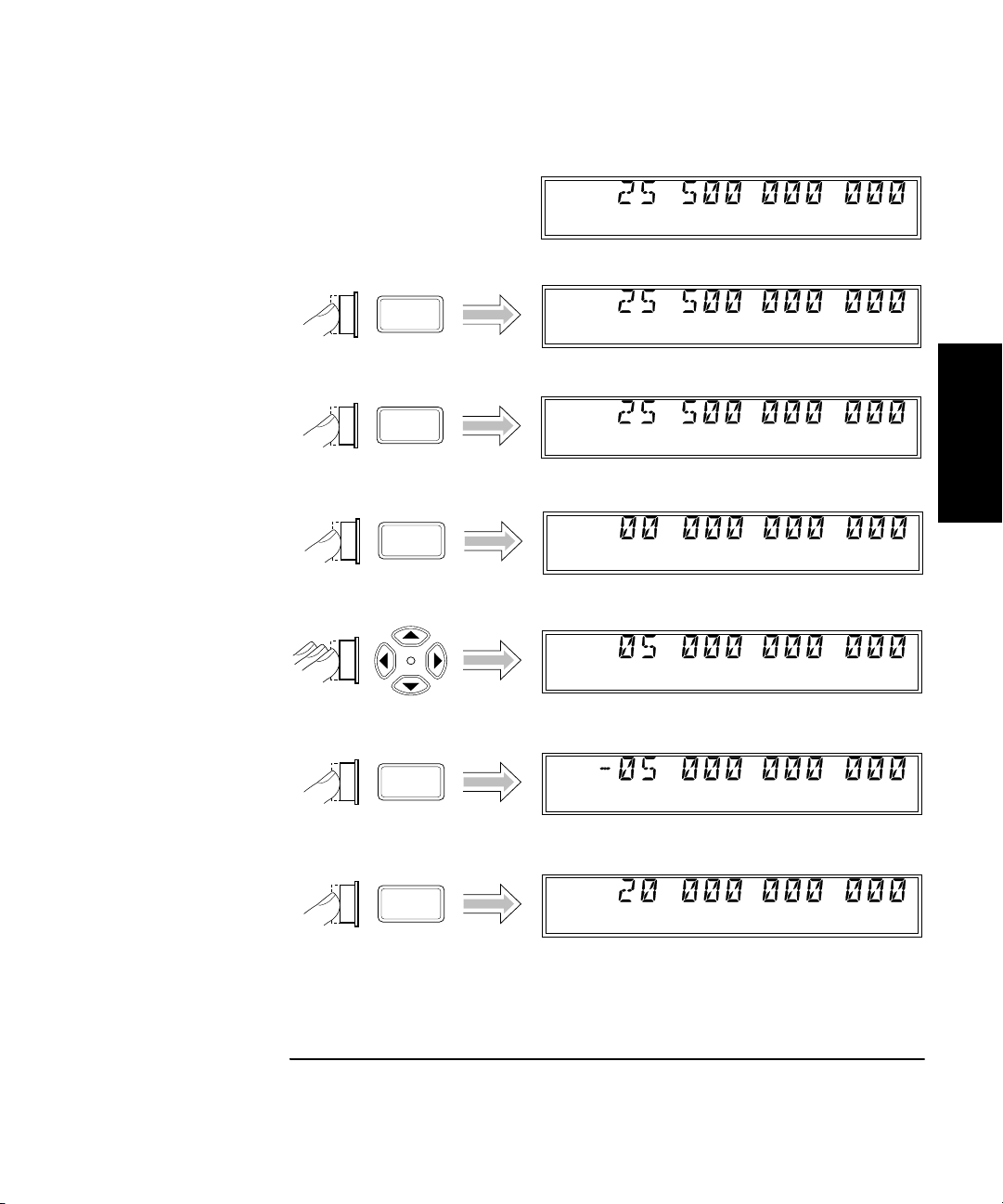
Offsetting a Frequency Measurement
You can use the Frequency Offset (Freq Offset) function to add or subtract
a constant value to/from a frequency measurement. For example, you can
use an offset to compensate for a systematic error or to display the
difference in frequency between two signals.
NOTE The Frequency Offset and Relative Frequency functions can be used
simultaneously.
To display an offset frequency measurement, you need to set the value and
1
NOTE When you are entering a value for Frequency Offset (or Power Offset),
sign (+/–) of the offset and to turn the Frequency Offset function on. In the
diagram on the next page, the Frequency Offset function is enabled first,
and the offset value is then entered. However, the order doesn’t matter,
so you can also enter the offset value first, and then turn the offset
function on.
you can use the Reset key to restore all of the displayed digits to zero.
These are the only two functions in which the Reset key has this effect.
1-20 Operating Guide
Page 39
Chapter 1 Getting Started
Operating the Counter
Offset
On/Off
Shift
Freq
Offset
Rate
Ch 2
Freq
Ch 2
Freq
Offset
Ch 2
Freq
Offset
Freq
Offset
1
Shift
Freq
Offset
+/-
Enter
Freq
Offset
Ch 2
Freq
Offset
Operating Guide 1-21
Page 40
Chapter 1 Getting Started
Operating the Counter
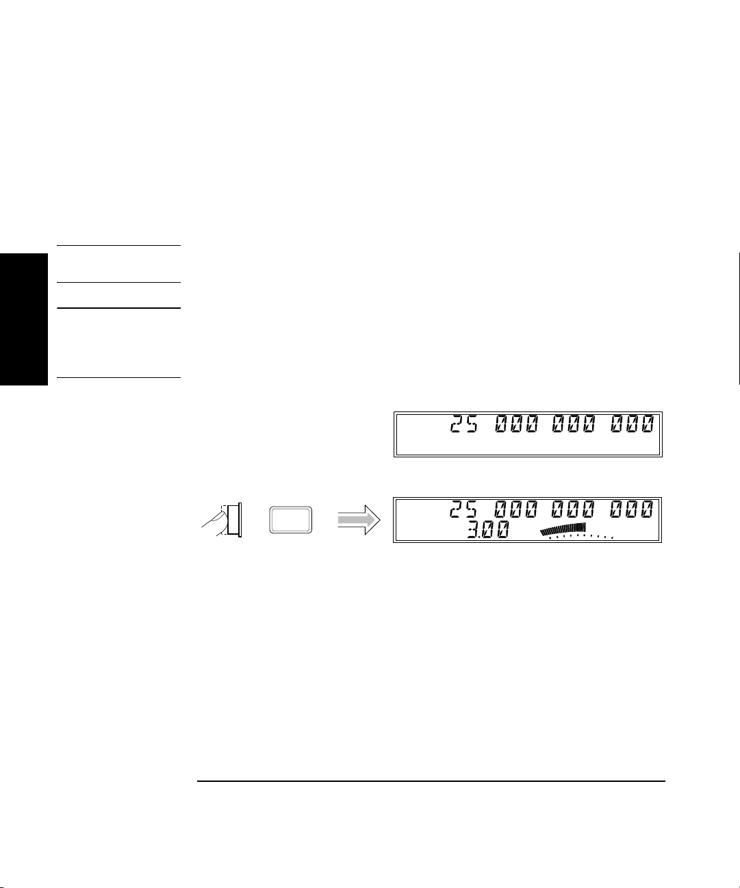
Measuring Power (Channel 2 Only)
The Agilent 53150A/151A/152A Counter can measure signal power (in the
same frequency ranges as for frequency measurements) on Channel 2.
The example procedure for measuring power in the following diagram
assumes that the Counter has previously been set up to measure a 25 GHz
input on Channel 2.
NOTE When the power of a signal applied to the Channel 2 input exceeds the
maximum rated power for the instrument, the Counter displays HI.
CAUTION The Channel 2 input path circuits contain sensitive GaAs semiconductors.
1
To prevent damage to these components, always adhere to standard ESD
(Electro-Static Discharge) prevention procedures, and ensure that the
maximum power specification for this channel (+27 dBm) is not exceeded.
Ch 2
Freq
Ch 2
Display
Power
Freq
Pwr
dBm
1-22 Operating Guide
Page 41
Chapter 1 Getting Started
Operating the Counter
Selecting the Unit of Measurement for Power
The Counter’s power-measurement function can display values in either
of two sets of units of measurement—dB and dBm or W, mW, and µW
(the Counter automatically selects the most appropriate unit when either
set of units is selected). Use the procedure in the following diagram to
select the unit of measurement for power (this procedure assumes that a
signal is currently applied on Channel 2 and that power is being displayed):
Ch 2
Shift
Freq
Pwr
Ch 2
Freq
Pwr
dBm
dBm
Shift
1
dBm/W
Display
Power
Ch 2
Freq
Pwr
mW
NOTE The Counter is specified for signals having amplitudes of up to +7.00 dBm.
If a signal having an amplitude greater than +9 or +10 dBm is applied,
and power measurement is enabled, the annunciators for the power
reading display “HI” to indicate that the signal’s amplitude exceeds the
specification. If a signal having an amplitude of less than –40.00 dBm is
applied, the power annunciators display “LO” to indicate that the signal
level is too low to be measured by this instrument.
CAUTION The Channel 2 input path circuits contain sensitive GaAs semiconductors.
To prevent damage to these components, always adhere to standard ESD
(Electro-Static Discharge) prevention procedures, and ensure that the
maximum power specification for this channel (+27.00 dBm) is not exceeded.
Operating Guide 1-23
Page 42

Chapter 1 Getting Started
Offset
On/Off
Operating the Counter
Measuring Relative Power
You can measure the difference in power from one measurement to
another (drift) using the Relative Power function. You do this by pressing
the Shift and Rel Pwr (Offset On/Off) keys, as shown in the diagram below
(this example assumes that a signal is currently applied to Channel 2).
The Counter stores the current power reading when you press the
Rel Pwr key. It then subtracts this value from all subsequent readings
and displays the difference until you press the Rel Pwr key again.
Ch 2
Freq
1
Shift
Pwr
Ch 2
Freq
Pwr
dBm
dBm
Shift
Rel Pwr
Offset
On/Off
Ch 2
Freq
Rel Pwr
dB
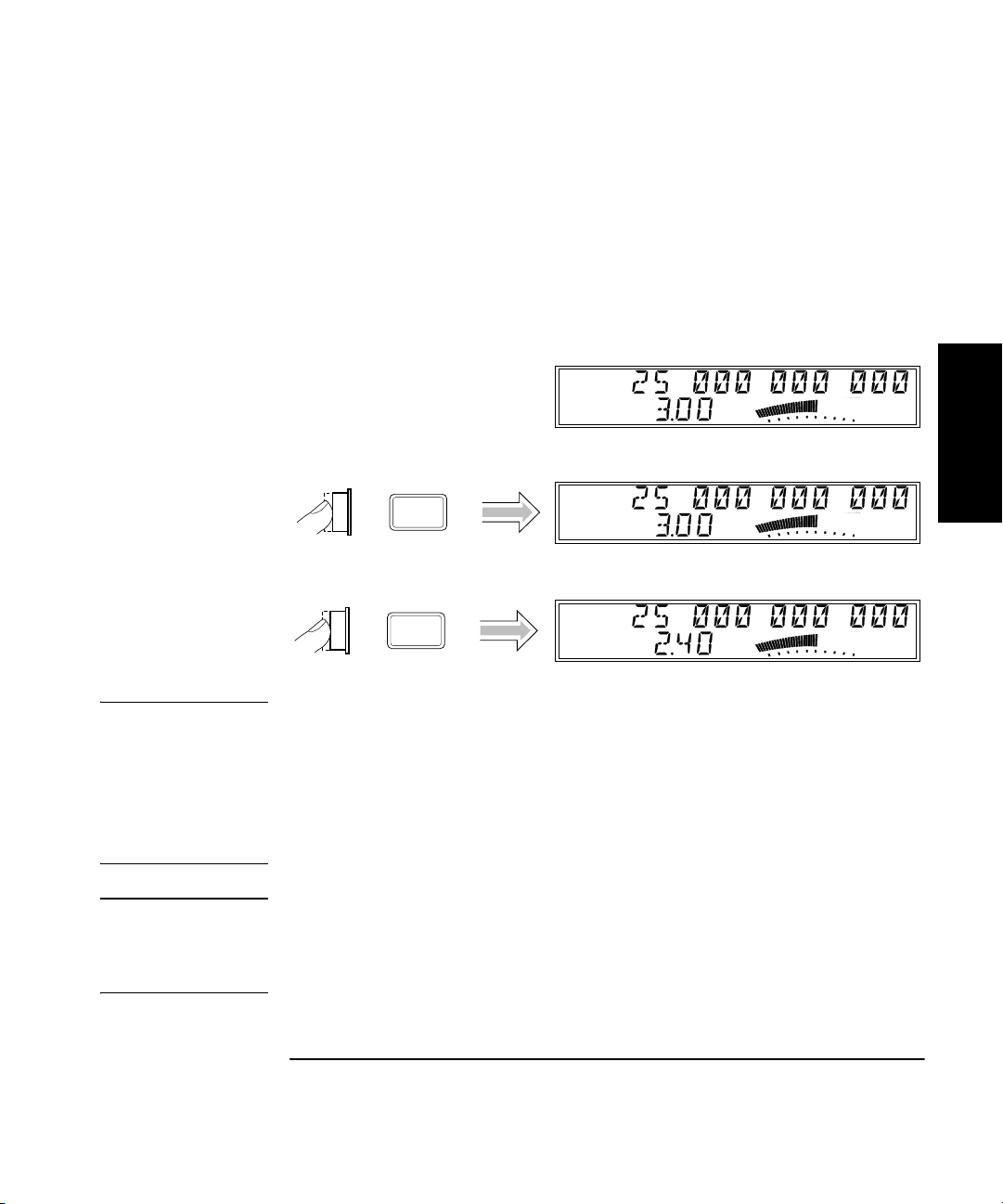
Offsetting a Power Measurement
You can use the Power Offset (Pwr Offset) function to add or subtract a
constant value to/from a power measurement. For example, you can use
an offset to compensate for a systematic error or to display the difference
in power between two signals.
NOTE The Power Offset and Relative Power functions can be used simultaneously.
To display an offset power measurement, you need to set the value and
sign (+/–) of the offset and to turn the Power Offset function on. In the
following diagram, the Power Offset function is enabled first, and the
1-24 Operating Guide
Page 43

Chapter 1 Getting Started
Avg
Operating the Counter
offset value is then entered. However, the order doesn’t matter, so you can
also enter the offset value first, and then turn the offset function on.
Ch 2
Freq
Pwr
dBm
Rel Pwr
Offset
On/Off
Shift
Pwr
Offset
Avg
+/-
Ch 2
Freq
Pwr
Offset
Ch 2
Freq
Pwr
Offset
Pwr
Offset
Pwr
Offset
Pwr
Offset
dB
1
dB
Shift
dB
dB
dB
Ch 2
Enter
Freq
Pwr
Offset
dB
Operating Guide 1-25
Page 44

Chapter 1 Getting Started
Operating the Counter
Using Power Correction
The Power Correction function in the main Menu allows you to set the
Counter to automatically compensate for power loss (or gain) that occurs in
the test configuration, such as attenuation resulting from cable impedance.
You can choose from nine power-correction profiles that are stored in
nonvolatile memory, and you can modify the contents of these profiles.
Each profile is defined by two to ten data points (a data point consists of
a loss value and a frequency value). When Power Correction is enabled,
the Counter automatically adds a correction to the power reading
(determined from the data points in the profile) that compensates for the
1
loss (or gain) at the frequency being measured. When a measured
frequency does not match any of the frequency values defined in the
currently selected profile, the Counter interpolates for the measured
frequency to determine the appropriate value to add to the power
measurement. The correction profiles require a minimum of two data
points per profile.
Power Correction Theory of Operation
When the Counter interpolates between data points to determine the
amount of correction to apply to the current measurement, it computes
the correction based on a straight line plotted between the frequency
values in the two closest data points. Therefore, a graph of a powercorrection profile would show a “curve” that consists of two to nine
straight-line segments, rather than a true curve, as shown below.
P
o
w
e
r
F r e q u e n c y
1-26 Operating Guide
Page 45

Chapter 1 Getting Started
Operating the Counter
NOTE As the graph shows, the Counter never computes power-correction values
for loss above the zero axis. Conversely, corrections are never computed
for gain below the zero axis. Once the correction value reaches the zero
axis, no further corrections are applied.
When the Counter interpolates for frequencies that are above or below the
range of frequencies specified in the currently selected profile, it never
computes a value that would fall on the opposite side of the zero axis from
the closest specified frequency. In other words, if there are two or more
data points that contain loss values, the Counter never computes or
applies a correction that would be indicative of gain. Conversely, if there
are two or more data points that contain gain values (negative loss values),
the Counter never applies a correction that would be indicative of loss.
Since there can be no further change in the loss or gain values once the
zero axis is reached, no power corrections are applied when the input
frequency reaches or passes a point in the profile that intersects the zero
axis. Effectively, the Counter computes only loss-correction values or
gain-correction values—never both within the same profile.
When you enter values in power-correction data points and then exit the
data-point display (using either the left-arrow key or the Enter key), the
Counter immediately sorts all of the data-points into order by the
frequency values. Therefore, if you enter a pair of values in a data point,
exit the data-point display, and then immediately return to the display for
that data point, you may see different values than the ones you just
entered. The values you entered may now be contained in a differently
numbered data point in the same profile, if they were previously entered
out of order by frequency.
1
Increasing Profile Accuracy
To increase the accuracy of a power-correction profile, you can add data
points between the existing data points in the profile (if less than 10 data
points are in use), thus bringing the data points closer together and
shortening the straight-line segments. If all ten data points are in use,
you can add data points by using two or more profiles for a single test
configuration. If you do this, you must select the profile you need (from the
Menu) for the range of frequencies being measured. This means that you
must select a different profile whenever the measured frequency moves
outside the range of frequencies defined by the data points in the
currently selected profile.
Operating Guide 1-27
Page 46

Chapter 1 Getting Started
Operating the Counter
Selecting a Power-Correction Profile
The diagram on page 1-29 shows how to turn Power Correction on or off
and how to select a power-correction profile.
NOTE Pressing the Enter key when the number of a power-correction profile
(1-9) is displayed selects that profile, enables Power Correction, and exits
the Menu. If you intend to enter data in the currently displayed profile,
press the right-arrow key instead of the Enter key to select the
power-correction profile without exiting the Menu.
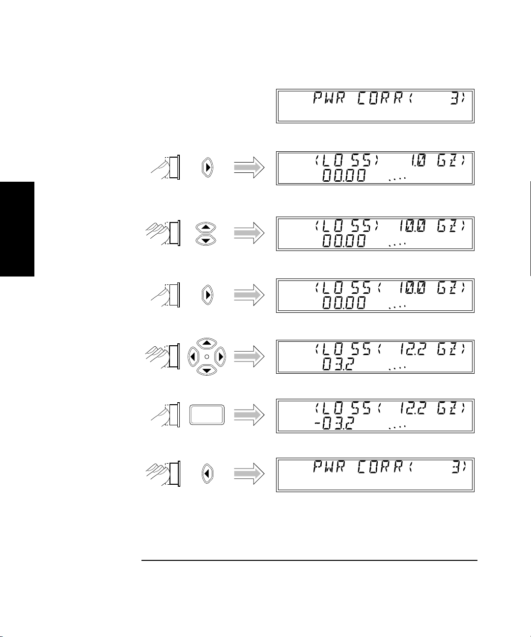
Entering Data Points in a Power-Correction Profile
1
The diagram on page 1-30 shows how to enter data points (frequency and
loss values) in power-correction profiles. A minimum of two valid data
points is required for Power Correction; you can enter up to ten data
points in each power-correction profile. Each of the power-correction
profiles initially contains two valid data points—0.0 dB loss at 1 GHz,
and 0.0 dB loss at the highest frequency the Counter can measure
(20 GHz for the 53150A, 26.5 GHz for the 53151A, or 46 GHz for the 53152A).
The remaining eight data points contain values of 0.0 dB loss at 0.0 GHz.
When entering data, you can change the values in an existing data point
or enter new values in a data point that currently has zero values.
1-28 Operating Guide
Page 47

Chapter 1 Getting Started
Operating the Counter
Shift
Menu
Reset/
Local
Ch 2
Freq
Pwr
Ch 2
Freq
Pwr
dBm
dBm
Shift
1
Ch 2
Enter
Freq
Pwr
dBm
Shift
NOTE When Power Correction is enabled, a lower-case letter “c” is displayed in
the hundredths position of the power display.
Operating Guide 1-29
Page 48
Chapter 1 Getting Started
dB
dB
dB
Operating the Counter
dB
1
+/-
dB
dB
dB
dB
1-30 Operating Guide
Page 49

Chapter 1 Getting Started
Operating the Counter
NOTES Pressing the Enter key after entering values exits the Menu and restores
the measurement display. To remain in the Power Correction menu so you
can enter or change values in another data point in the currently selected,
press the left-arrow key repeatedly (after entering the values for a data
point) until “PWR CORR” is re-displayed, and then press the up- or downarrow key to choose the next data point you want to edit.
When you are entering or editing values in data points, the 10 single-line
annunciators that are part of the analog power display are used to
indicate which data point is being displayed. The left-most annunciator
indicates that the data displayed is contained in the lowest data point,
data point 1. When the first two annunciators on the left are activated,
this indicates data point 2, and so on through data point 10, which is
indicated by all 10 annunciators.
The Power Correction function can be used to correct for gain from
amplification as well as for loss from attenuation. Since Power Correction
is intended primarily to correct for loss, loss values are entered as positive
numbers. To enter values for gain, use the Sign key (+/–) to change the
sign of the value you enter.
1
Operating Guide 1-31
Page 50
Chapter 1 Getting Started
Operating the Counter
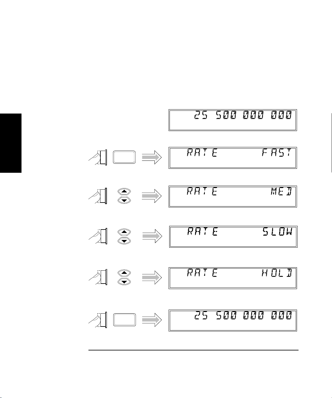
Setting the Measurement Rate
The measurement rate determines how frequently the Counter takes
measurements. You can set the measurement rate to FAST, MED
(medium), SLOW, or HOLD (single measurement taken each time you
press the Reset/Local key).
Ch 2
Freq
1
Rate
Ch 2
Enter
Freq
Hold
1-32 Operating Guide
Page 51
Chapter 1 Getting Started
Operating the Counter
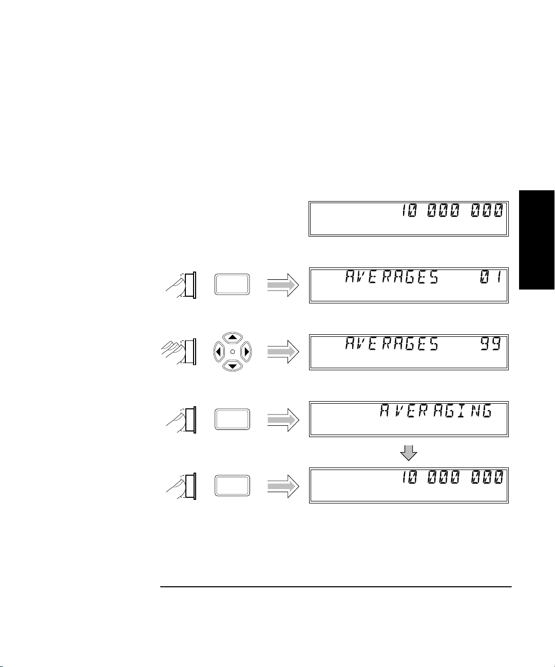
Setting the Number of Averages
You can set the number of measurements the Counter takes and averages
before displaying the result. The default setting is one (no average
computations are performed when the number of averages is set to one),
and the maximum setting is 99. Note that the tens position (10 through 90)
and the units position (0 through 9) are adjusted separately, and that you
cannot set the number of averages to zero.
Ch 1
Freq
Avg
1
Ch 1
Enter
Enter
Freq
Avg On
Ch 1
Freq
Avg On
Operating Guide 1-33
Page 52

Chapter 1 Getting Started
Operating the Counter
NOTE For most of the Counter’s settings, when you continue to press either the
up-arrow or the down-arrow key when you reach the end of the available
settings, the value for the setting “rolls over” to the value at the opposite
end of the range. For example, if the GPIB address is set to 31, and you
press the up-arrow key, the value changes to one.
However, when you adjust the value in the units position for the number
of measurements to be averaged, rollover does not occur. If you press the
up-arrow when the value in the tens position is zero and the value in the
units position is nine, or if you press the down-arrow when the value in
the tens position is zero and the value in the units position is one, there is
1
NOTE When the resolution setting is high (e.g., 1 Hz), and a large number of
no change. If the value in the units position could roll over (in either
direction), it would allow you to set a value of zero for the number of
averages. Since at least one measurement must be taken, zero is an
illegal value.
averages is selected, it takes a considerable amount of time for the
Counter to take the measurements, compute the averages, and display a
reading. As a result, the rate at which the display is updated is
considerably slower than at small numbers of averages and lower
resolution settings. For example, when the resolution is set to 1 Hz,
and the number of averages is set to 60, a new reading is displayed every
60 seconds (approximately).
Setting the Resolution
Since less time is required to compute each measurement as the
resolution of the measurements is reduced, the resolution setting affects
the rate at which measurements are taken and displayed, as well as the
number of digits displayed for the measurements. As a result, the rate at
which the Gate indicator flashes changes when you change the resolution.
As shown in the procedure in the diagram on the next page, the available
resolution settings are 1 Hz (the default setting), 10 Hz, 100 Hz, 1 KHz,
10 KHz, 100 KHz, and 1 MHz.
1-34 Operating Guide
Page 53

Chapter 1 Getting Started
Operating the Counter
Resol
Ch 2
Freq
1
Ch 2
Enter
Freq
Operating Guide 1-35
Page 54

Chapter 1 Getting Started
Operating the Counter
1
1-36 Operating Guide
Page 55

2
Operating Your Frequency Counter
Page 56

Chapter 2 Operating Your Frequency Counter
Introduction
Introduction
This chapter contains information and usage procedures for the
front-panel keys, operating functions, and menus of the
Agilent 53150A/151A/152A Microwave Frequency Counter.
Chapter Summary
• How this Counter Works for You pg. 2-3
• Summary of the Measurement Sequence pg. 2-4
• Using the Selection Keys pg. 2-5
• Numeric Entry pg. 2-6
• Changing States pg. 2-7
• Acknowledging Messages pg. 2-9
• Using the Clear and Reset/Local Keys pg. 2-9
2
• Other Function Selection Keys pg. 2-10
• Measuring Frequency pg. 2-12
• Setting the Resolution and Measurement Rate pg. 2-14
• Setting the Number of Averages pg. 2-17
• Measuring Relative Frequency pg. 2-20
• Offsetting a Frequency Measurement pg. 2-21
• Measuring Power pg. 2-24
• Measuring Relative Power pg. 2-26
• Offsetting a Power Measurement pg. 2-27
• Using Power Correction pg. 2-30
• Using the Menu pg. 2-39
2-2 Operating Guide
Page 57

Chapter 2 Operating Your Frequency Counter
How this Counter Works for You
How this Counter Works for You
The following is a list of some of the key things the Counter does for you.
• Presets the menus to default states and values at power-up
• The Counter’s Menu key and other front-panel keys allow you to select
such things as the timebase source, the GPIB address, and the RS-232
serial-port baud rate. The Counter also allows you to store your
selections in non-volatile memory; thus, these settings are not lost
when power has been off or after a remote-interface reset.
• Automatically displays measurement(s) when you have selected a
measurement function.
• Accepts your entry for a menu item when you press the Enter key.
You must press the Enter key to complete each setting and/or selection.
• Saves user configuration settings.
Operating Guide 2-3
2
Page 58

Chapter 2 Operating Your Frequency Counter
Summary of the Measurement Sequence
Summary of the Measurement Sequence
1. Turn on the Main ~ Power switch on the back panel, and then press and
release the POWER button on the front panel.
NOTE The internal Reference Oscillator receives power only when the
Main ~ Power switch is on. Therefore, the frequency of the reference signal
may drift until the oscillator stabilizes. Specifications for the stability of
the standard internal timebase and the optional Oven Timebase are
provided in Chapter 3.
2. Connect the input signal to the appropriate input connector (Channel 1
or Channel 2).
3. Connect an external reference signal to the External Reference
connector on the back panel (if desired).
4. Press the Chan Select key to select the input channel (if necessary).
2
5. Press the Display Power key if you need to measure power (Channel 2
only).
6. Press the frequency and/or power Offset On/Off keys to enable offset
measurements (if desired), and then use the Freq Offset (Shift + Rate)
and/or Pwr Offset (Shift + Avg) keys to enter the offset values.
7. Use the Resol, Rate, and Avg keys to configure the display.
8. Use the Menu (Shift + Reset/Local) key to set the reference-oscillator
source, to select the Channel 1 low-pass filter, to configure the
Counter’s response to frequency modulation, to enable and configure
Power Correction, and/or to select a previously saved set of user
settings.
9. If you intend to operate the counter remotely using the GPIB, use the
GPIB (Shift + Resol) key to configure the GPIB.
10. If you intend to operate the counter remotely using the serial
interface, use the Menu (Shift + Reset/Local) key to adjust the serial
port Baud rate.
2-4 Operating Guide
Page 59

Chapter 2 Operating Your Frequency Counter
Enter
+/-
Using the Selection Keys
Using the Selection Keys
There are six Selection keys—four “arrow” keys, the Enter key, and the
sign (+/–) key. The functions of the arrow keys depend on the Counter’s
operating mode (i.e., sequencing through choices in the Menu, numeric
entry, state change, etc.). This section describes how the Selection keys
function in these different operating modes.
Sequencing Through the Menu
To access the Menu, press the Shift key, and then press the Menu
(Reset/Local) key.
Menu
Reset/
Local
• Press the up- or down-arrow key to go forward to the next menu
function or back to the previous menu function. Pressing either of these
keys repeatedly cycles through the list of menu functions.
Shift
• Press the right-arrow key to select a function. When you do this, the
flashing annunciator ( ) changes direction and the current setting
flashes to indicate that you can now use the up- and down-arrow keys
to cycle through the available settings.
• Press the up- or down-arrow key to move through the list of available
settings for a function. Pressing either of these keys repeatedly cycles
through the list of settings.
• Press the Sign (+/–) key to change the sign of numeric values.
• Press the Enter key to accept the currently displayed setting and exit
the Menu.
NOTE In most cases, when you reach the top or bottom of a list of settings, or the
left or right end of a numerical field, the focus rolls over to the opposite
end of the list of settings, or wraps around to the opposite end of the
numeric field. In some situations, however, this does not occur, because if
it did, you could choose an illegal setting. For these settings, you have to
use the opposite button to cycle back through the values or settings.
2
Operating Guide 2-5
Page 60

Chapter 2 Operating Your Frequency Counter
Enter
+/-
Using the Selection Keys
Numeric Entry
Several menu functions, and several functions that have dedicated keys
on the front panel, require you to enter numeric values.
• Press the (left-arrow) and (right-arrow) keys to move left and
right to select adjustable digits (the selected digit flashes).
• Press the (up-arrow) and/or (down-arrow) key to increment and
decrement the selected (flashing) digit of the displayed value (see note
on previous page).
• Press the Sign (+/–) key to change the sign of the numeric value.
• Press the Enter key to complete a numeric entry. (If you change the
value of a numeric entry, but you forget to press the Enter key, the
value of the entry is not changed.)
2
2-6 Operating Guide
Page 61

Chapter 2 Operating Your Frequency Counter
Using the Selection Keys
Changing States
Several menu functions, and several functions that have dedicated keys
on the front panel, require you to choose from a list of available states.
These functions and the states you can choose for each of them are:
• Reference Oscillator (REF OSC)
– Internal (INT)
–External (EXT)
• Serial Port Baud Rate (BAUD)
– 1200
– 2400
– 4800
– 9600
– 14400
– 19200
• Frequency Modulation (FM)
2
–Automatic (AUTO)
–Off (OFF)
• Channel 1 Low-Pass Filter (CH1 LPF)
–On (ON)
–Off (OFF)
• Measurement Rate (Rate key)
–Fast (FAS T)
–Medium (MED)
–Slow (SLOW)
–Hold (HOLD)
• Resolution (Resol key)
– 1 Hz, 10 Hz, 100 Hz, 1 KHz, 10 KHz, 100 KHz, 1 MHz
Operating Guide 2-7
Page 62

Chapter 2 Operating Your Frequency Counter
Using the Selection Keys
Use the Selection keys as described below to change the state of these
functions:
• When the annunciator ( ) in the display flashes, press the right-arrow
key to move the focus from the displayed menu function (or frontpanel-key function) to the setting for that function.
• Press the up- or down-arrow key to cycle through the available choices.
Press the Enter key to complete the setting. (If you change the setting of a
function, but you forget to press the Enter key, the setting of the function
is not changed.)
NOTE The Sign key has no function and is ignored in menu selections and
front-panel functions that have state-change selections only.
2
2-8 Operating Guide
Page 63

Chapter 2 Operating Your Frequency Counter
Reset/
Local
Freq
Offset
On/Off
Clear
Rate
Shift
Menu
Using the Clear and Reset/Local Keys
Using the Clear and Reset/Local Keys
The Clear key and the Reset/Local key have similar functions in the
Menu and in other front-panel-key function settings, but their effects vary
with the Counter’s state and condition. In general, the Reset/Local key
restores the setting that was in effect when you entered the Menu or
front-panel-key function, but it does not close the Menu or the
function-setting display. The Clear key also restores the previous setting,
but it closes the Menu or the front-panel-key function-setting display at
the same time.
If you press the Reset/Local key while the Counter is taking
measurements, it resets the current operation and forces the Counter to
reacquire and re-measure the signal.
Pressing the Reset/Local key while the Counter is in Remote Mode forces
the Counter into Local Mode and enables all of the front-panel controls.
Acknowledging Messages
When a message is displayed, press the Reset/Local key, the Clear key,
or the Enter key (after reading the message) to acknowledge it and erase it
from the display.
Operating Guide 2-9
2
Page 64
Chapter 2 Operating Your Frequency Counter
MODIFY
GPIB
Pwr
Offset
Freq
Offset
On/Off
Resol
Avg
+/-+/-
Clear
Rate
Enter
MO
Pwr
Offset
Freq
Offset
On/Off
Avg
+/-+/-
Clear
Rate
POWER
FREQ
Gate
Rel Freq
Rel Pwr
dBm/ W
Channel 2
Chan
Select
Offset
On/Off
Offset
On/Off
Display
Power
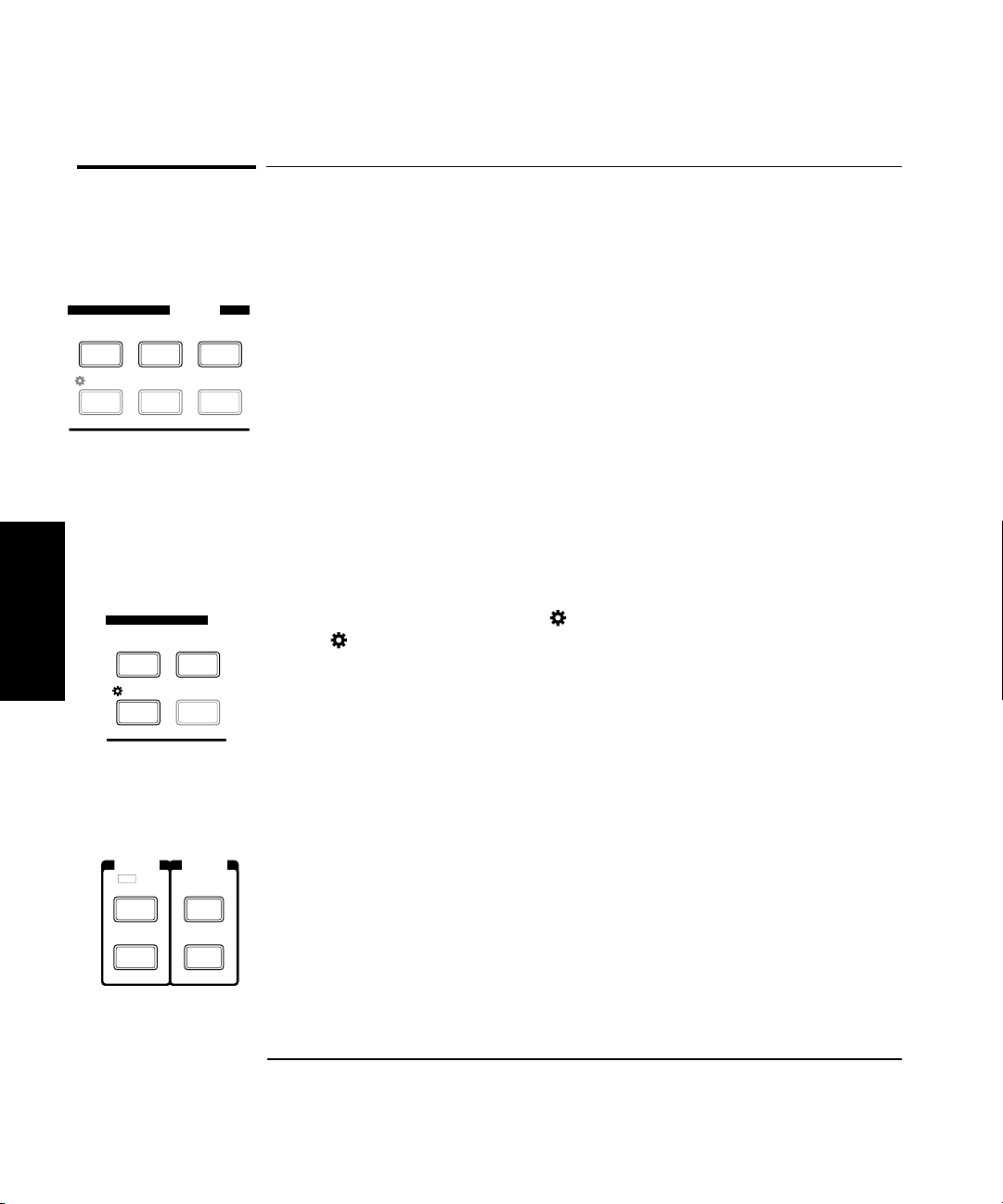
Other Function Selection Keys
Other Function Selection Keys
There are several functions that you access directly from front-panel keys
(not from within the Menu). These functions are:
• Measurement Rate (Rate key)
• Number of Averages (Avg key)
• Display Resolution (Resol key)
• GPIB Address (GPIB key)
Use the Selection keys in the manner described earlier in this chapter
(see “Numeric Entry” and “Changing States”) to adjust the settings for
these functions. Detailed procedures for using the Rate, Avg, Resol, and
GPIB keys are provided later in this chapter.
There are also a number of functions that are toggled between states
(no selections are displayed) using named front-panel keys. These are:
2
• Display backlight on and off ( On/Off). Press Shift, and then press
the On/Off / Clear key.
• Channel selection (Chan Select). Press Chan Select to switch between
the two input channels.
• Display power measurement (Display Power). Press Display Power to
turn the power-measurement function on and off.
• Frequency offset measurement (FREQ Offset On/Off). Press the Offset
On/Off key in the FREQ area of the front panel to turn the frequency
offset function on or off.
• Power offset measurement (POWER Offset On/Off). Press the Offset
On/Off key in the POWER area of the front panel to turn the power
offset function on or off (the Display Power function must be on).
2-10 Operating Guide
Page 65

Chapter 2 Operating Your Frequency Counter
Other Function Selection Keys
• Relative frequency measurement (Rel Freq). Press Shift, and then
press the Rel Freq (Offset On/Off) key to measure the difference in
frequency between the current measurement and the measurement
taken at the time you pressed the Rel Freq key (drift).
• Relative power measurement (Rel Pwr). Press Shift, and then press the
Rel Pwr (Offset On/Off) key to measure the difference in power
between the current measurement and the measurement taken at the
time you pressed the Rel Pwr key.
Operating Guide 2-11
2
Page 66
Chapter 2 Operating Your Frequency Counter
Main ~ Power
CHANNEL 2
50 MHz to 20 GHz
DAMAGE
+27 dBm
50!Ω
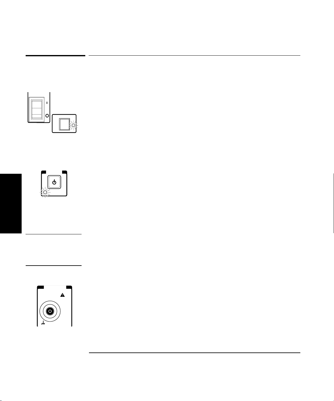
Measuring Frequency
Measuring Frequency
1 Connect the Counter to a power source, and set the
Main ~ Power switch on the back panel to 1 (on).
If the Counter is connected to an AC power source, the Main AC Power
indicator on the back panel and the Standby indicator on the front panel
light. If the Counter is connected to an external DC power source or is
operated from internal batteries (with Battery option only), the Standby
indicator lights, but the Main AC Power indicator does not.
2Press the POWER button on the front panel.
The Standby indicator goes off, and all segments of the front-panel display
POWER
Standby
2
are temporarily activated. TESTING is displayed while the Counter
performs its power-on self-test. If the Counter passes all of the tests,
SELF TEST OK is displayed, and the Counter then displays its model
number, firmware version number, GPIB address, and CH2 NO SIGNAL.
The Counter is now ready to measure the frequency of a signal applied to
the Channel 2 input. Note that the Ch 2 and Freq annunciators are activated.
3 Connect an input signal to Channel 2.
CAUTION The Channel 2 input path circuits contain sensitive GaAs semiconductors.
To prevent damage to these components, always adhere to standard ESD
(ElectroStatic Discharge) prevention procedures, and ensure that the
maximum power specification for this channel (+27 dBm) is not exceeded.
The Counter automatically displays the measured frequency of the input
signal. To set the resolution, measurement rate, and/or the number of
averages, see the appropriate procedure in the section titled “Operating
the Counter,” or refer to “Setting the Resolution,” “Setting the
Measurement Rate,” and “Setting the Number of Averages,” later in this
chapter.
2-12 Operating Guide
Page 67

Chapter 2 Operating Your Frequency Counter
Measuring Frequency
NOTE When the frequency of a signal applied to the Channel 2 input exceeds the
maximum rated frequency for the instrument, the Counter displays
CH2 TOO HIGH.
4 To measure the frequency of a signal applied to the Channel 1
input, press the Chan Select key.
FREQ
Chan
Select
Gate
CHANNEL 1 is displayed momentarily, and the Ch 1 and Freq annunciators
are activated. If a signal is presently applied to the Channel 1 input, the
measured frequency is then displayed. If no signal is applied, CH1 NO
SIGNAL is displayed until an input signal is connected to the Channel 1
input connector.
2
Operating Guide 2-13
Page 68
Chapter 2 Operating Your Frequency Counter
Setting the Resolution and Measurement Rate
Setting the Resolution and Measurement Rate
The number of measurements the Counter makes in a given amount of
time is affected by the Rate setting, the Resolution setting, and the quality
of the input signal (signal quality affects the amount of time the Counter
requires to determine an accurate measurement). By adjusting the
Resolution and Rate settings, you can affect how often the Counter
takes measurements.
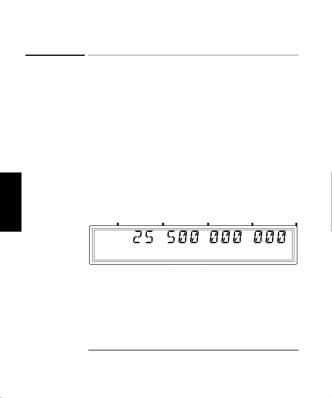
Setting the Resolution
The Counter’s resolution setting determines the number of digits displayed
for measurements and the precision of the measurements. Since less time
is required to compute each measurement as the resolution of the
measurements is reduced, the resolution setting also affects the rate at
which measurements are taken and displayed. As a result, the flash rate
of the Gate indicator changes when you change the resolution.
The numerals shown for the value of the measurement are displayed in
2
four groups of three digits, as shown below (the leading zero is suppressed):
Ch 2
Freq
GHz
MHz
kHz
Hz
2-14 Operating Guide
Page 69

Chapter 2 Operating Your Frequency Counter
Enter
GPIB
Resol
Setting the Resolution and Measurement Rate
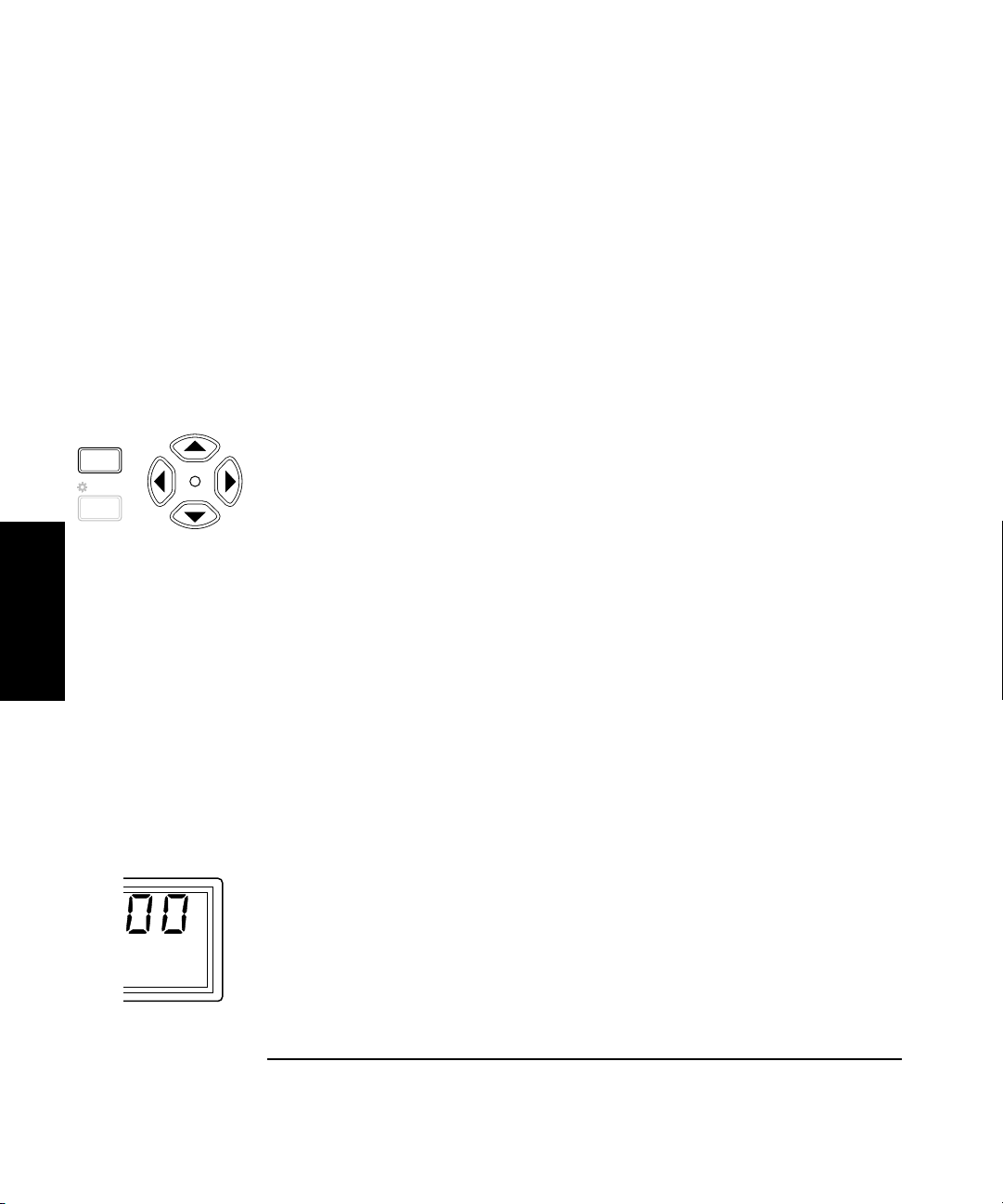
Resolution Setting Example
For the following example, use the 10 MHz output from the reference
timebase as the input to Channel 1.
1 Press the Resol key to enter the resolution-setting mode.
The current resolution setting is displayed (the current value and the
indicator between the arrow keys are flashing to indicate that you can use
the up- and down-arrow keys to change the setting).
2 Press the up-arrow or down-arrow key to decrease or increase
the resolution.
You can press these keys as many times as necessary to locate the setting
you want to use. The available resolution settings are 1 Hz (the default
setting), 10 Hz, 100 Hz, 1 KHz, 10 KHz, 100 KHz, and 1 MHz.
3Press the Enter key to activate your setting and exit the
resolution-setting mode.
The setting you chose is now in effect. The number of digits displayed for
the measurement is adjusted accordingly; you can observe the affect on
measurement speed by monitoring the flash rate of the Gate indicator.
2
NOTE The measurement resolution has a direct effect on the amount of time the
Counter requires to complete a measurement. Measurements made at the
Counter’s maximum resolution setting (1 Hz) are noticeably slower than
at lower resolutions. This is especially noticeable when the Counter is set
to average a number of measurements.
Operating Guide 2-15
Page 70
Chapter 2 Operating Your Frequency Counter
Freq
Offset
Clear
Rate
On/Off
Hold
Setting the Resolution and Measurement Rate
Setting the Measurement Rate
The measurement Rate setting determines how frequently the counter
initiates measurements. Since the actual measurement rate is also
affected by the resolution setting and the signal quality, as mentioned
earlier, the available rate settings (FAST, MED, and SLOW) do not equate
to a fixed number of measurements in a given amount of time.The HOLD
setting turns off automatic measurements, so that a single measurement
is made each time you press the Reset/Local key.
Rate Setting Example
1 Press the Rate key to enter the rate-setting mode.
The current rate setting is displayed (the current value and the indicator
between the arrow keys are flashing to indicate that you can use the upand down-arrow keys to change the setting).
2 Press the up-arrow or down-arrow key to decrease or increase the
measurement rate.
2
You can press these keys as many times as necessary to locate the setting
you want to use. The available resolution settings are FAST, MED, SLOW,
and HOLD.
3Press the Enter key to activate your setting and exit the rate-
setting mode.
The setting you chose is now in effect. The measurement rate is adjusted
accordingly; you can observe the effect on measurement speed by
monitoring the flash rate of the Gate indicator. There is no annunciator
on the display for the rate setting, unless you set the rate to HOLD.
4 If you set the rate to HOLD, press the Reset/Local key to initiate
a measurement.
The Counter displays the MEASURING message while it computes the
measurement, and then displays the result. Press the Reset/Local key
again each time you want to take an additional measurement.
2-16 Operating Guide
Page 71

Chapter 2 Operating Your Frequency Counter
Pwr
Offset
+/–
Avg
Setting the Number of Averages
Setting the Number of Averages
You can set the Counter to take a variable number of frequency, power,
or voltage measurements and average them mathematically before
displaying the result. You can use this feature to determine the effective
measurement of a signal that is fluctuating. When measuring the
frequency of a fluctuating signal, you can also use averaging to retain
some of the precision of a maximum-resolution measurement.
The default number of averages is 1, which means that no averages are
performed, and the maximum setting is 99. Note that the tens position
(10 through 90) and the units position (0 through 9) are adjusted
separately, and that it is not possible to set the number of averages to 0.
NOTE When a large number of averages is selected for a frequency measurement
in combination with a high resolution setting (e.g., 1 Hz), it takes a
considerable amount of time for the Counter to take the measurements,
compute the averages, and display an initial reading. For example, when
the number of averages is set to 60, and the resolution is set to 1 Hz, the
first reading is displayed after 60 seconds (approximately). Subsequent
computations do not require as much time, since the averaging function
computes a running average. However, the rate at which the display is
updated after the initial average computation is also slower than at lower
resolution settings.
2
Averages Setting Example
1 Press the Avg key to enter the averages-setting mode.
The current averages setting is displayed (the current value and the
indicator between the arrow keys are flashing to indicate that you can use
the up- and down-arrow keys to change the setting).
2 Press the up-arrow or down-arrow key to decrease or increase the
value for the units position of the number of averages.
Operating Guide 2-17
Page 72

Chapter 2 Operating Your Frequency Counter
Ch 12
Rel Freq
Avg On
Setting the Number of Averages
NOTE For most of the Counter’s settings, when you continue to press either the
up-arrow or the down-arrow key when you reach the end of the available
settings, the value for the setting “rolls over” to the value at the opposite
end of the range. For example, if the GPIB address is set to 31, and you
press the up-arrow key, the value changes to 1. However, when you adjust
the value in the units position for the number of measurements to be
averaged, rollover does not occur. If you press the up-arrow when the
value in the tens position is 0 and the value in the units position is 9, or if
you press the down-arrow when the value in the tens position is 0 and the
value in the units position is 1, there is no change. If the value in the units
position could roll over (in either direction), it would allow you to set a
value of 0 for the number of averages. Since at least one measurement
must be taken, 0 is an illegal value.
3 Press the left-arrow key once to move the focus to the tens
position, and then use the up- and/or down-arrow key to set the
value for the tens position (if desired).
Note that the tens and units values are set separately.
2
4Press the Enter key to activate your setting and exit the averages-
setting mode.
The Avg On annunciator is activated, and the Counter displays AVERAGING
while it takes the first set of measurements. The length of time that the
AVERAGI N G message is displayed varies primarily with setting for the
number of averages, since this determines the number of measurements
that must be made and averaged before displaying a result. When the first
set of averages is complete and the result is displayed, the Counter
immediately takes another measurement, discards the oldest
measurement included in the current average computation, recomputes
the average and displays the new result. This continues until you change
the setting for the number of averages or disable averaging (by setting the
number of averages to 0).
2-18 Operating Guide
Page 73

Chapter 2 Operating Your Frequency Counter
Setting the Number of Averages
In certain situations, the length of time that the AVERAGING message is
displayed can be affected by additional factors. When you are measuring
frequency, the current resolution setting, the rate setting, and the quality
of the signal all affect the length of time required to make the
measurements and complete the average computation.
If the measurement rate is set to HOLD, and a value larger than 1 is set
for averages, the first set of measurements is not initiated until you press
the Reset/Local key. When you do, the Counter displays the AVERAG I N G
message while it takes the first set of measurements. When the first set of
measurements is complete, and the averaging result is displayed, the
Counter remains in this state until you press the Reset/Local key to
initiate another set of measurements, change the value for averages back
to one, or change the setting for the measurement rate to SLOW, MED,
or HIGH. When the measurement rate is set to HOLD, the Counter performs a
block-average computation instead of a running-average computation.
Operating Guide 2-19
2
Page 74

Chapter 2 Operating Your Frequency Counter
Ch 2
Rel Freq
Measuring Relative Frequency
Measuring Relative Frequency
You can measure the difference in frequency from one measurement to
another (frequency drift) or between two separate input signals using the
Relative Frequency function.
Relative Frequency Example
Press the Shift key, and then press the Rel Freq (FREQ Offset On/Off)
key. The Shift annunciator activates when you press the Shift key. When
you press the Rel Freq (FREQ Offset On/Off) key, the Shift annunciator
disappears, and the Rel Freq annunciator in the upper-left corner of the
display activates. At the same time, the Counter saves the frequency
measurement it was displaying at the time you pressed the Rel Freq key,
and it computes and displays the difference between that measurement
and the current measurement.
You can also use the Relative Frequency function to measure the
difference between two different signals. To do this, activate the Relative
2
Frequency function, as described in the previous paragraph, disconnect
the cable supplying the signal to the input connector, and then connect the
second signal to the same input connector. The value displayed when the
Counter acquires the second signal is the frequency difference between
the two signals.
2-20 Operating Guide
Page 75

Chapter 2 Operating Your Frequency Counter
Rel
Offsetting a Frequency Measurement
Offsetting a Frequency Measurement
You can use the Frequency Offset (Freq Offset) function to add or subtract
a constant value to/from a frequency measurement. For example, you can
use an offset to compensate for a systematic error or to display the
difference in frequency between two signals.
To display an offset frequency measurement, you need to set the value and
sign (+/–) of the offset and to turn the Frequency Offset function on. In the
following example, the Frequency Offset function is enabled first, and the
offset value is then entered. However, the order doesn’t matter, so you can
also enter the offset value first, and then turn the offset function on.
Frequency Offset Example
1 Connect a cable from the 10 MHz reference output on the back
panel to the Channel 1 input connector, and press the Chan Select
key (if necessary) to activate Channel 1.
The display should look like this:
2
GHz
Ch 1
Freq
Rel
MHz
kHz
Hz
2Press the Shift key, and then press the Freq Offset (Rate) key.
The Shift annunciator activates when you press the Shift key. When you
press the Freq Offset key, the Shift annunciator disappears, and the Freq
Offset annunciator at the left side of the display activates.
Operating Guide 2-21
Page 76

Chapter 2 Operating Your Frequency Counter
Rel
Offsetting a Frequency Measurement
3 Use the left- and right-arrow keys to move the focus to the digit(s)
in the frequency-offset display that you need to adjust to enter the
offset value, and then use the up- and down-arrow keys to adjust
the value for each digit. Enter a value of 500 Hz.
The flashing digit is the digit that currently has the focus. This means
that you can change the value of the flashing digit using the up- and
down-arrow keys.
4 Press the sign (+/–) key (if desired) to change the sign of the offset
value.
The display should look like this:
GHz
Ch 1
Freq
Rel
Offset
MHz
kHz
2
5Press the Enter key to confirm the offset value and exit the
offset-entry display.
The Freq Offset annunciator is deactivated, and the measurement
display returns.
NOTE When you are entering a value for Frequency Offset (or Power Offset),
you can use the Reset key to restore all of the displayed digits to zero.
These are the only two functions in which the Reset key has this effect.
Hz
2-22 Operating Guide
Page 77

Chapter 2 Operating Your Frequency Counter
Offsetting a Frequency Measurement
6Press the Offset On/Off key.
The Freq Offset annunciator is activated, and the value of the display is
adjusted to reflect the value and sign of the offset entered in Steps 2 and 3.
The display should look like this:
Ch 1
Rel Freq
Offset
GHz
MHz
kHz
Since the offset function can be used to add or subtract a fixed value
to/from the measurement result, you can use this feature to tune or align
the odd frequencies of a local oscillator (LO). If you enter the target
frequency as a negative offset, the Counter displays the difference
between the LO’s frequency and the target frequency. You can then adjust
the LO until the Counter displays a value of zero.
NOTE The maximum value that can be entered for Frequency Offset is
± 49,999,999,999 Hz.
Hz
2
Operating Guide 2-23
Page 78

Chapter 2 Operating Your Frequency Counter
Measuring Power
Measuring Power
The Agilent 53150A/53151A/53152A can also measure signal power
(in the same frequency ranges as for frequency measurements) on
Channel 2. The power measurement, which is shown in a dedicated area
of the display, includes a digital readout and an analog representation
that is useful when peaking signals. The display can be configured to show
power in units of dB, dBm, W, mW, µW, and percentage (%).
CAUTION The Channel 2 input path circuits contain sensitive GaAs semiconductors.
To prevent damage to these components, always adhere to standard ESD
(ElectroStatic Discharge) prevention procedures, and ensure that the
maximum power specification for this channel (+27 dBm) is not exceeded.
Power Measurement Example
This example assumes that a signal is currently applied to the Channel 2
input connector.
2
1Press the Display Power key to enable power measurement.
The Pwr annunciator at the left side of the display is activated, and the
Counter’s digital and analog power displays show the power measurement
in dB or dBm (the default units of measurement).
The display should look like this:
Ch 12
Rel Freq
dB
dBm
Rel Pwr
Watts
mW
uW
%
2-24 Operating Guide
Page 79

Chapter 2 Operating Your Frequency Counter
Measuring Power
2Press the Shift key, and then press the dBm/W (Display Power) key.
When you press the Shift key, the Shift annunciator is activated. When you
press the dBm/W (Display Power) key, the Shift annunciator goes off, and
the units of measurement annunciator group to the right of the digital power
measurement changes from dB or dBm to W, mW, or µW, as shown below:
Ch 12
Rel Freq
dB
dBm
Rel Pwr
Watts
mW
uW
%
NOTE When the power of a signal applied to the Channel 2 input exceeds the
maximum rated power for the instrument, the Counter displays HI.
Operating Guide 2-25
2
Page 80

Chapter 2 Operating Your Frequency Counter
Ch 12
Rel Freq
Rel Pwr
Measuring Relative Power
Measuring Relative Power
You can measure the difference in power from one measurement to another
or between two separate input signals using the Relative Power function.
Relative Power Example
Press the Shift key, and then press the Rel Pwr (PWR Offset On/Off) key.
The Shift annunciator activates when you press the Shift key. When you
press the Rel Pwr key, the Shift annunciator disappears, and the Rel Pwr
annunciator at the left side of the display activates. At the same time, the
Counter saves the power measurement it was displaying at the time you
pressed the Rel Pwr key, and it computes and displays the difference in
power between that measurement and the current measurement.
NOTE When the Counter is set to measure power in dBm, relative power is
expressed in dB. When the Counter is set to measure power in Watts, mW,
or, µW, power relative power is expressed as a percentage (%).
2
You can also use the Relative Power function to measure the difference in
power between two different signals. To do this, activate the Relative
Power function, as described in the previous paragraph, disconnect the
cable supplying the signal to the input connector, and then connect the
second signal to the same input connector. The value displayed when the
Counter acquires the second signal is the power difference between the
two signals.
2-26 Operating Guide
Page 81
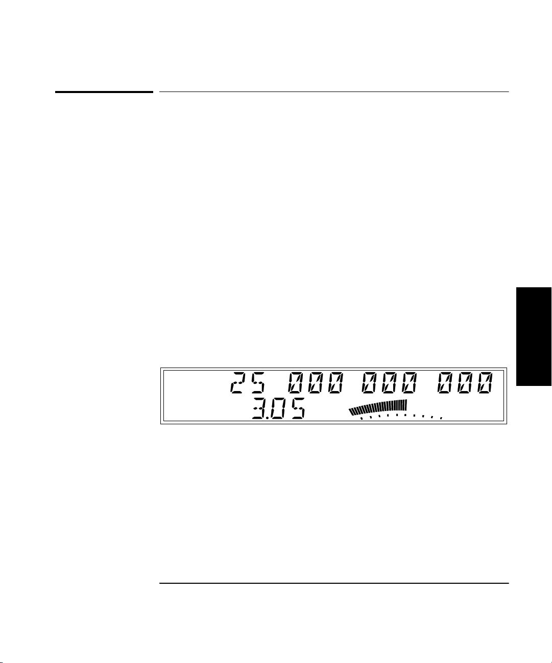
Chapter 2 Operating Your Frequency Counter
Offsetting a Power Measurement
Offsetting a Power Measurement
You can use the Power Offset (Pwr Offset) function to add or subtract a
constant value to/from a power measurement. For example, you can use
an offset to compensate for a systematic error, to display the difference in
power between two signals, or to compensate for losses and attenuation in
cables or components that are between the signal source and the Counter.
To display an offset power measurement, you set the value and sign (+/–)
of the offset and turn the Power Offset function on. In the following
example, the Power Offset function is enabled first, and the offset value is
then entered. However, the order doesn’t matter, so you can also enter the
offset value first, and then turn the offset function on.
Power Offset Example
1 Connect a signal to the Channel 2 input connector, and activate
power measurement by pressing the Display Power key.
The display should look like this (except for the values, which are
simulated in the illustration):
2
Ch 12
Rel Freq
dB
dBm
Rel Pwr
Watts
mW
uW
%
Operating Guide 2-27
Page 82

Chapter 2 Operating Your Frequency Counter
Offsetting a Power Measurement
2 Press the Shift key, and then press the Pwr Offset (Avg) key.
The Shift annunciator activates when you press the Shift key. When you
press the Pwr Offset key, the Shift annunciator and the frequency display
disappear, the Pwr Offset annunciator at the left side of the display
activates, and the power offset value is set to 00.00, as shown below:
Ch 12
Rel Freq
dB
dB
Rel Pwr
Offset
Watts
mW
uW
%
3 Use the left- and right-arrow keys to move the focus to the digit(s)
in the power-offset display that you need to adjust to enter the
offset value, and then use the up- and down-arrow keys to adjust
the value for each digit.
The flashing digit is the digit that currently has the focus. This means
2
that you can change the value of the flashing digit using the up- and
down-arrow keys.
NOTE If you enter a value for Power Offset that results in a power reading that
is out of the Counter’s specified power-measurement range, the Counter
displays HI in the power display when the Power Offset function is
enabled.
4 Press the Sign (+/–) key (if desired) to change the sign of the
offset value.
Ch 12
Rel Freq
dB
dB
Rel Pwr
Offset
Watts
mW
uW
%
2-28 Operating Guide
Page 83
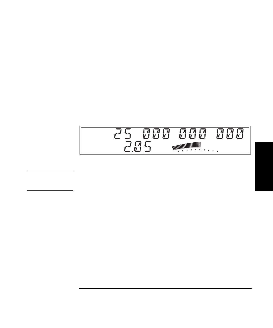
Chapter 2 Operating Your Frequency Counter
Offsetting a Power Measurement
5Press the Enter key to confirm the offset value and exit the offset-
entry display.
The Pwr Offset annunciator is deactivated, and the measurement display
returns.
6Press the Offset On/Off key (in the POWER area of the front panel).
The Pwr Offset annunciator is activated, and the value of the display is
adjusted to reflect the value and sign of the offset entered in Steps 3 and 4.
The display should now look like this (values are simulated):
Ch 12
Rel Freq
dB
dB
Rel Pwr
Offset
Watts
mW
uW
%
NOTE When you are entering a value for Power Offset (or Frequency Offset),
you can use the Reset key to restore all of the displayed digits to zero.
These are the only two functions in which the Reset key has this effect.
Operating Guide 2-29
2
Page 84

Chapter 2 Operating Your Frequency Counter
Using Power Correction
Using Power Correction
The Power Correction function in the main Menu allows you to set the
Counter to automatically compensate for power loss (or gain) that occurs
in the test configuration, such as attenuation resulting from cable
impedance. You can choose from nine power-correction profiles that are
stored in nonvolatile memory, and you can modify the contents of these
profiles.
Each profile is defined by two to ten data points (a data point consists of a
loss value and a frequency value). When Power Correction is enabled, the
Counter automatically adds a correction to the power reading (determined
from the data points in the profile) that compensates for the loss (or gain)
at the frequency being measured. When a measured frequency does not
match any of the frequency values defined in the currently selected
profile, the Counter interpolates for the measured frequency to determine
the appropriate loss value to add to the power measurement.
2
A minimum of two valid data points is required for Power Correction; you
can enter up to ten data points in each power-correction profile. Each of
the power-correction profiles initially contains two valid data points—
0.0 dB loss at 1 GHz, and 0.0 dB loss at the highest frequency the Counter
can measure (20 GHz for the 53150A, 26.5 GHz for the 53151A, or 46 GHz
for the 53152A). The remaining eight data points contain values of 0.0 dB
loss at 0.0 GHz. When entering data, you can change the values in an
existing data point or enter new values in a data point that currently has
zero values. The data points are automatically sorted into order by
frequency as you finish entering each one.
2-30 Operating Guide
Page 85
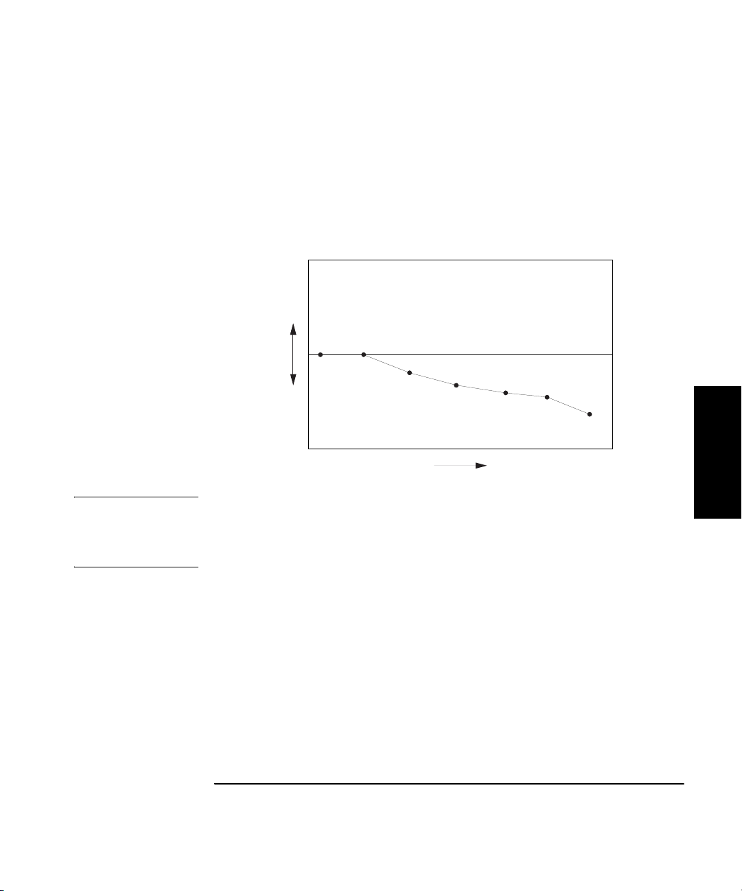
Chapter 2 Operating Your Frequency Counter
y
Using Power Correction
Power Correction Theory of Operation
When the Counter interpolates between data points to determine the
amount of correction to apply to the current measurement, it computes the
correction based on a straight line plotted between the frequency values in
the two closest data points. Therefore, a graph of a power-correction
profile would show a “curve” that consists of two to nine straight-line
segments, rather than a true curve, as shown below.
P
o
w
e
r
F r e q u e n c
NOTE When the frequency value of a signal is beyond either end of the curve
specified by the values in the currently selected profile’s data points,
the Counter computes a correction by extending the straight line defined
in the last two data points in the profile.
As the graph above shows, the Counter never computes power-correction
values for loss above the zero axis. Conversely, corrections are never
computed for gain below the zero axis. When the Counter interpolates for
frequencies that are above or below the range of frequencies specified in
the currently selected profile, it never computes a value that would fall on
the opposite side of the zero axis from the closest specified frequency.
In other words, if there are two or more data points that contain loss
values, the Counter never computes or applies a correction that would be
indicative of gain. Conversely, if there are two or more data points that
contain gain values (negative loss values), the Counter never applies a
correction that would be indicative of loss.
Operating Guide 2-31
2
Page 86

Chapter 2 Operating Your Frequency Counter
Using Power Correction
Since there can be no further change in the loss or gain values once the
zero axis is reached, no power corrections are applied when the input
frequency reaches or passes a point in the profile that intersects the zero
axis. Effectively, the Counter computes only loss-correction values or gaincorrection values—never both within the same profile.
When you enter values in power-correction data points and then exit the
data-point display (using either the left-arrow key or the Enter key),
the Counter immediately sorts all of the data-points into order by the
frequency values. Therefore, if you enter a pair of values in a data point,
exit the data-point display, and then immediately return to the display for
that data point, you may see different values than the ones you just entered.
The values you entered may now be contained in a differently numbered
data point in the same profile, if they were previously entered out of order
by frequency.
Increasing Profile Accuracy
To increase the accuracy of a power-correction profile, you can add data
points between the existing data points in the profile (if less than 10 data
2
points are in use), thus bringing the data points closer together and
shortening the straight-line segments. If all ten data points are in use,
you can add data points by using two or more profiles for a single test
configuration. If you do this, you must select the profile you need (from the
Menu) for the range of frequencies being measured. This means that you
must select a different profile whenever the measured frequency moves
outside the range of frequencies defined by the data points in the
currently selected profile.
Power Correction Examples
The procedures for using Power Correction and entering loss (or gain) and
frequency values in power-correction profiles are demonstrated in the
Power Correction examples on the following pages. The first example,
on page 2-33, shows how to select a power-correction profile and enable
Power Correction and also shows how to disable Power Correction.
The second example, on page page 2-35, shows how to enter data in the
power-correction profiles.
2-32 Operating Guide
Page 87

Chapter 2 Operating Your Frequency Counter
Using Power Correction
Power Correction Example: Selecting a Correction Profile
1Press the Shift key, and then press the Menu (Reset/Local) key.
2 Press either the up- or down-arrow key repeatedly until “PWR
CORR > OFF” is displayed as shown below:
3 Press the right-arrow key once.
The flashing pointer in the Power Correction display changes direction
to indicate that you can now use the up- and down-arrow keys to select a
power-correction profile (or select OFF to disable Power Correction).
The current setting for Power Correction (OFF or a number between 1
and 9) also flashes.
2
4 Press the up- and/or down-arrow key repeatedly until the number
of the power-correction profile you want to use is displayed.
For this example, choose profile number 3.
If no data points were entered into the correction profiles previously,
each of the nine power-correction profiles contains only two valid data
points—0.0 dB loss at 1 GHz and 0.0 dB loss at the highest frequency the
Counter can measure (20 GHz for the 53150A, 26.5 GHz for the 53151A,
or 46 GHz for the 53152A). The remaining eight data points in each of the
profiles initially contain values of 0.0 dB loss at 0.0 GHz. (This example
assumes that valid loss and frequency values were previously entered in
two or more of the data points in this profile.)
Operating Guide 2-33
Page 88

Chapter 2 Operating Your Frequency Counter
Using Power Correction
5Press the Enter key to select profile number 3.
Power Correction is enabled using profile number 3, and the measurement
display returns. The power reading now includes an adjustment for the
loss incurred at the measured frequency. The amount of the adjustment is
derived from the loss and frequency values in the data points in the
selected profile. A lower-case letter “c” is shown in the hundredths
position of the power-measurement display to indicate that Power
Correction is enabled.
Ch 2
Freq
Pwr
dBm
NOTE Pressing the Enter key when the number of a power-correction profile
(1-9) is displayed selects that profile, enables Power Correction, and exits
the Menu. If you intend to enter data in the currently displayed profile,
2
press the right-arrow key instead of the Enter key to select the
power-correction profile without exiting the Menu.
You can also select a power-correction profile by pressing the right- or
left-arrow key (instead of the Enter key). When you press either arrow
key, you do not exit the Menu. As the next example shows, you should
select a profile with the right-arrow key when you intend to enter or
change the loss and/or frequency values in the selected profile. You should
select the power-correction profile with the left-arrow key if you are done
working with the power-correction settings, but you want to change
settings for other functions in the Menu.
2-34 Operating Guide
Page 89
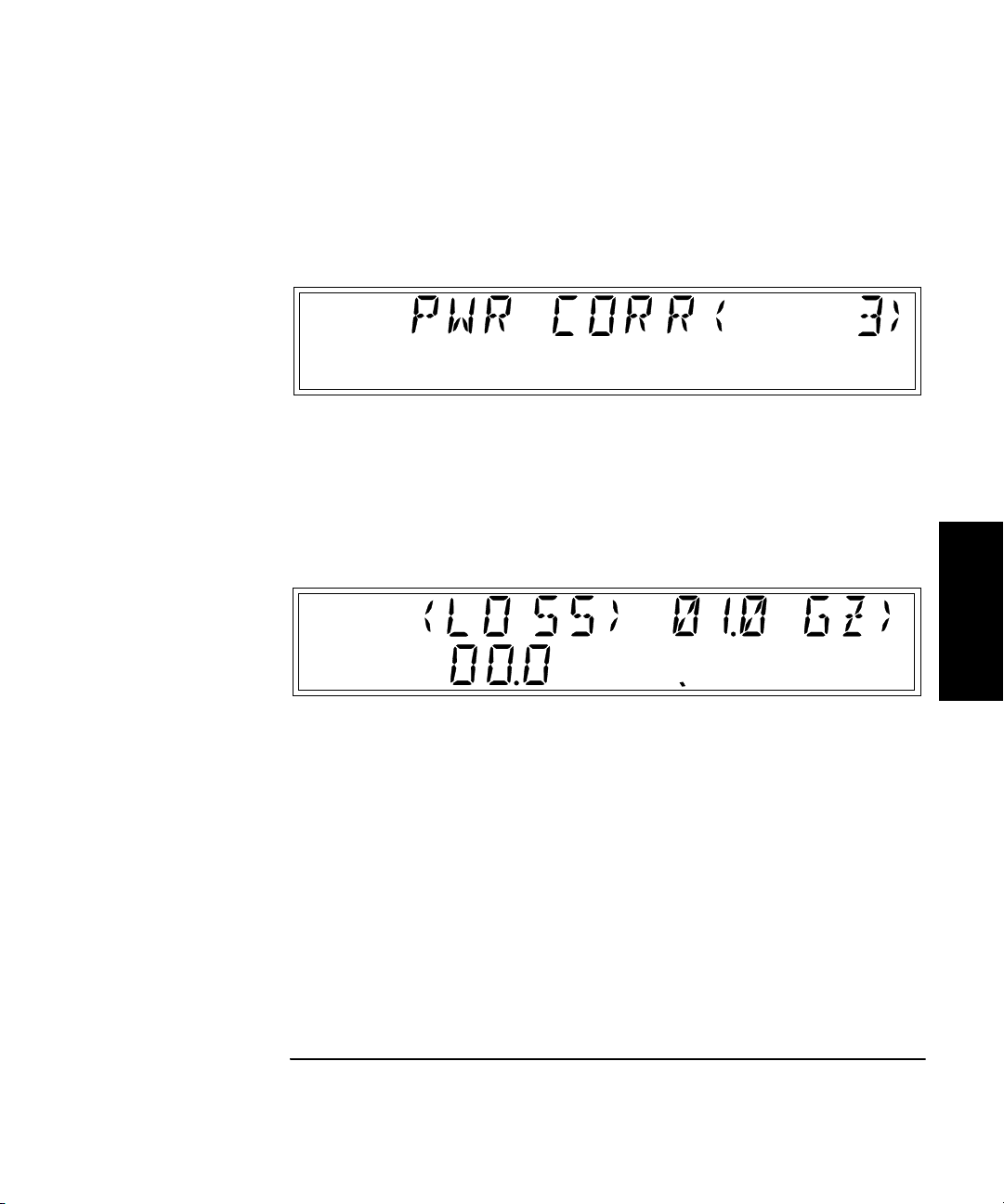
Chapter 2 Operating Your Frequency Counter
Using Power Correction
Power Correction Example: Editing Data Point Values
1 Select a power-correction profile using the up- and/or
down-arrow keys (as shown in steps 1 through 4 in the previous
example). For this example, choose profile number 3.
2 Press the right-arrow key.
The display changes to show the loss and frequency values stored in the
data point that contains the lowest frequency value in the current profile.
The left and right pointers that are before and after the word “LOSS” are
flashing.
dB
The ten small, single-line annunciators that are below the analog power
display are used to indicate which of the ten data points is currently
displayed. In the example shown above, only the first annunciator is
activated, which indicates that the values displayed are for data point 1,
the lowest data point.
Operating Guide 2-35
2
Page 90

Chapter 2 Operating Your Frequency Counter
Using Power Correction
3 To insert values in an empty data point, press the up- and/or
down-arrow key repeatedly to cycle through the data points in
the selected profile to locate one that contains values of 0.0 for
both loss and frequency.
For a profile that has not been previously used, the first two data points
displayed contain values of 00.0 dB loss at 1.0 GHz and 00.0 dB loss at the
highest frequency the Counter can measure (20 GHz for the 53150A,
26.5 GHz for the 53151A, or 46 GHz for the 53152A). The remaining data
points contain values of 00.0 dB loss at 00.0 GHz. In profiles that have
been previously used, all data points containing non-zero values are
displayed in order from lowest to highest, and any zero-value data points
are displayed above the non-zero data points. All data points are
automatically sorted into order by frequency and saved whenever you
select a different profile or exit the Power Correction menu.
4 To change a value (or values) in a data point, press the up- and/or
down-arrow key repeatedly until the data point that contains the
value(s) you want to change is displayed, and then press the
right-arrow key (the number of the data point displayed is
2
indicated by the number of annunciators to the right of the
loss value).
The pointer to the left of the word “LOSS” stops flashing, the pointer to
the right of the word “LOSS” changes direction and flashes, and the first
digit of the frequency value flashes. This indicates that you can now
adjust the value of the first digit in the frequency setting.
dB
5 To adjust the value of the tens position of the frequency setting,
press the up- or down-arrow key until the desired value is
displayed.
2-36 Operating Guide
Page 91

Chapter 2 Operating Your Frequency Counter
Using Power Correction
6 Use the right-arrow key to move to each of the remaining digits in
the frequency setting, and use up- and down-arrow keys to adjust
their values, if necessary.
The currently selected digit flashes to indicate that it is the one that
changes when you press the up- and down-arrow keys. You can also use
the left-arrow key to back up to a previous digit, if necessary. However,
be aware that the digit to the left of the one you are adjusting increments
automatically to the next higher or lower value when the value of the
currently selected digit exceeds nine or is incremented below zero.
7 To adjust the loss value, press the right-arrow key while the digit
in the tenths position of the frequency value and the pointer to
the right of “GZ” are flashing.
The pointer at the right end of the display changes direction, and the first
digit (tens position) of the loss value flashes. You can now adjust its value
using the up- and down-arrow keys.
8 Use the left- and right-arrow keys to navigate to the remaining
digits in the loss setting, and adjust their values (if necessary)
with the up- and down-arrow keys.
dB
9 Press the Sign (+/–) key to change the sign of the loss value
(if necessary).
dB
Operating Guide 2-37
2
Page 92

Chapter 2 Operating Your Frequency Counter
Using Power Correction
10 To add or adjust the values in another data point, press the
left-arrow key repeatedly until “PWR CORR” is re-displayed, and
repeat steps 2 through 10. To edit data points within another
power-correction profile, press the left-arrow key repeatedly until
“PWR CORR” is re-displayed, and repeat steps 1 through 10.
NOTE When a data point is entered in a profile, all of the data points in that
profile are sorted by frequency and stored in that order. Therefore,
the data points in a profile are always in order from the lowest frequency
to the highest when you access a correction profile. The first data point
displayed is always the data point that contains the lowest frequency value.
11 If you are done entering data-point values, press the Enter key to
accept your changes, save the data-point values, and return to the
measurement display.
Power Correction is now enabled using the profile number 3.
2
Ch 2
Freq
Pwr
dBm
NOTE You can include your selection of a power-correction profile in any of the
nine sets of user settings stored in non-volatile memory (see page 2-46) by
enabling the profile and then saving the set. If you save set 0 (zero) while
Power-Correction is enabled, the currently-selected profile will be in effect
whenever you turn on the Counter.
The data in the saved user settings and in all of the power-correction
profiles is stored in non-volatile memory. If the Counter ever requires
repair, and the main circuit-board assembly is replaced, these stored
values will be lost. Therefore, to protect these values and ensure they are
available for future use, you should keep an external record of them.
2-38 Operating Guide
Page 93

Chapter 2 Operating Your Frequency Counter
Using the Menu
Using the Menu
The Agilent 53150A/151A/152A Counter’s Menu makes it easy to control
a number of the Counter’s features and functions. You use the Selection
(arrow) keys to navigate to the setting you want to change and then to
actually make the changes.
1 Press the Shift key and then the Menu (Reset/Local) key to display the Menu.
When you press the Shift key, the Shift annunciator (near the bottom-right
corner of the display) activates. When you press the Menu (Reset/Local)
key, the Shift annunciator goes off, and the first menu item is displayed.
If you have not previously invoked the Menu since you last turned the
Counter on, the first menu item is REF OSC, the Reference Oscillator.
2 Press the right-arrow key to change the setting for the Reference
Oscillator.
The flashing annunciator ( ) in the display reverses direction to indicate
that you can now change the setting by pressing either the up-arrow key
or the down-arrow key. In the case of the Reference Oscillator function,
which has only two possible settings (INTernal and EXTernal), pressing
either the up- arrow or the down-arrow has the same effect (it toggles the
setting from INT to EXT or from EXT to INT).
NOTE The Counter will not switch to EXTernal unless a suitable reference
signal is available at the External Reference connector.
Operating Guide 2-39
2
Page 94

Chapter 2 Operating Your Frequency Counter
Using the Menu
3Press the Enter key to activate the setting and exit the Menu.
The setting you chose is put into effect, and the Menu closes.
If you need to exit the Menu without changing any of the settings, press
the Clear key. To restore the setting of any menu item to the setting that
was in effect when you opened the Menu, press the Reset/Local key (this
restores the original setting for the current menu item but does not close
the Menu).
The Menu contains the following items (these items are displayed in the
order they are listed if you repeatedly press the up-arrow key after
opening the Menu):
• REF OSC — Sets the Counter to use the internal timebase or an external
timebase connected to the Reference connector on the back panel.
• DO SELF TEST — Starts the sequence of built-in tests.
• BATT VOLTAGE — Displays the current voltage level in the
rechargeable battery packs (only if the Battery option is installed).
2
• OP HRS — Displays the total number of hours the Counter has been in
operation since it was last calibrated.
• Model number, firmware version number, serial number, OPTNS
(installed options).
• PRESET — Resets all user-settable functions to the factory default
settings.
• BAUD — Sets the data rate for the RS-232 serial port.
• FM — Turns the Counter’s ability to compensate for frequency
modulation on (AUTO) or OFF.
• CH1 LPF — Turns the Channel 1 Low-Pass Filter (approx. 50 KHz) ON
or OFF.
• RECALL — Reads and implements a stored set of user settings from
one of nine (0 – 9) that are stored in non-volatile memory.
2-40 Operating Guide
Page 95

Chapter 2 Operating Your Frequency Counter
Using the Menu
• SAVE — Saves a copy of the current user settings in non-volatile
memory. Nine sets (0 – 8) can be saved, and set 0 is automatically read
on startup. To have the Counter automatically start up with your
preferred settings, save these settings in set 0.
• PWR CORR — Activates (or deactivates) the Power Correction function
and allows you to edit and select power-correction profiles. Power
Correction is used to compensate for losses in the test configuration,
such as attenuation resulting from cable impedance.
Each of these menu items is described in more detail on the following pages.
Navigating in the Menu and Changing Settings
When you select the Menu (with the Shift and Menu [Reset/Local] keys),
the indicator between the arrow keys flashes to indicate that the arrow
keys are now active. Since the Reference Oscillator setting is the first one
displayed when you invoke the Menu (unless you’ve used the Menu to
change another setting since you turned the Counter on), you don’t have to
use the up-arrow key or the down-arrow key to get to it.
When you press the right-arrow key, the flashing annunciator ( ) changes
direction, and the current setting for the Reference Oscillator INT
(internal) or EXT (external) flashes. This indicates that you can now
change this setting. Use either the up-arrow key or the down-arrow key to
change the setting.
If there are more than two settings available for the currently selected
function, you can cycle through the available settings by repeatedly
pressing either the up-arrow key or the down-arrow key. For example, to
change the setting for the Baud rate for the serial port, invoke the Menu,
and then repeatedly press the up-arrow or down-arrow key until BAUD is
shown on the display. Then, press the right-arrow key to select the BAUD
option, and press the up- or down-arrow repeatedly until the setting you
want is displayed. Finally, press the Enter key to implement your choice.
You navigate to and adjust the remaining settings available in the Menu
in the same manner. Each time you modify a setting and press the Enter
key, the Menu closes, so you have to reinvoke it each time to change
additional settings.
Operating Guide 2-41
2
Page 96

Chapter 2 Operating Your Frequency Counter
Using the Menu
Some of the menu items listed on the previous page provide information
only (no settings are required [or possible] for these), such as Battery
Voltage, Operation Hours, and information that identifies the Counter
(Agilent model number, firmware version number, serial number, and
installed option codes). These menu options are described in the
remainder of this chapter and also in “The Front Panel Menus at a
Glance” on page 1-4.
NOTE Always terminate each setting you change in a menu option by pressing
the
Enter key. You can abort any change while the Menu is displayed by
pressing the
you made to the current menu option, but they do not affect any of the
other menu options. The
but the Reset/Local key does not.
Reset/Local key or the Clear key. Both keys nullify the change
Clear key terminates the current menu session,
Reference Oscillator (REF OSC)
By default, the Counter uses its internal 10 MHz reference oscillator
(or the optional Oven Timebase, Option 001) as a timebase for all
2
measurements, unless REF OSC is set to EXT, and it detects a 1, 2, 5, or
10 MHz reference signal on the Reference connector on the back panel.
If an external reference signal is present, you can force the Counter to use
the internal reference oscillator by setting the REF OSC menu option
to INT.
The available settings are EXT (external) and INT (internal), and the
default setting is INT.
NOTE When REF OSC is set to internal (INT), the Counter outputs a 10 MHz,
1 V p-p signal on the Reference connector on the back panel.
2-42 Operating Guide
Page 97

Chapter 2 Operating Your Frequency Counter
Using the Menu
Do Self Test
The Counter automatically performs a series of tests on critical
components each time you turn it on. If at any time during operation,
you want to repeat these tests, you can do so by invoking the Menu,
navigating to DO SELF TEST, and pressing the Enter key.
The individual tests that comprise the Self Test, and the error messages
that are displayed if problems are detected, are described in Appendix B,
“Messages.”
Battery Voltage (BATT VOLTAGE)
If the Battery Option (Option 002) is installed, the current battery voltage
is displayed in digital and analog form in this menu item, so you can
estimate the remaining time that the Counter can operate from the
batteries. The batteries are fully charged when the voltage reading is
13.5 V, and the minimum battery voltage for proper operation is
approximately 10 V. For additional information on the Battery Option,
see Appendix C.
Operating Hours (OP HOURS)
This is an informational menu item that displays the total number of hours
the Counter has been in operation since its last calibration. This value does
not include Standby hours. This information is useful for scheduling
routine maintenance and calibration. For additional information on
maintenance and calibration, see the Agilent 53150A/151A/152A
Assembly-Level Service Guide.
Model Number, Firmware Version, Serial Number, and Option Codes
This menu item displays a series of numbers and codes that are used to
identify the Counter, its software version number, and the options that
are installed. These items are displayed sequentially, and you use the leftand right-arrow keys to move between the information fields. Note that
there are several numbers displayed in the field that contains the
firmware version. These are in the following pattern:
Operating Guide 2-43
2
Page 98

Chapter 2 Operating Your Frequency Counter
Using the Menu
VVV is the version number of the Counter’s firmware, and XX, YYY, and
ZZZZ are other numerical codes that are reserved for Agilent internal use.
The flashing annunciators at either end of the first line of the display
indicate that you can use the equivalent arrow key to scroll left and/or
right to the next field of information.
The option-code display lists the code number for each of the installed
options. For example, in a Counter that has the Battery and Oven
Timebase options installed, the display would show: <OPTNS 1-2- - ->.
2
2-44 Operating Guide
Page 99
Chapter 2 Operating Your Frequency Counter
Using the Menu
Preset
When PRESET is displayed, pressing the Enter key loads the default
settings for most of the Counter’s functions. These functions and their
default settings are listed in the following table:
Table 2-1. Factory Default Function Settings
Function Available Settings Default Setting
Reference Oscillator
(REF OSC)
Frequency Modulation (FM) AUTO, OFF AUTO
Channel 1 Low-Pass Filter
(CH1 LPF)
Recall Settings (RECALL) 0 through 8 0
Save Settings (SAVE) 0 through 8 0
Measurement Rate
(Rate key)
Averages (Avg key) 01 through 99 01
Resolution
(Resol key)
Display Backlight On/Off
( On/Off key)
Channel Selection
(Chan Select key)
Power Measurement Units
(dBm/W key)
Frequency Offset
(FREQ Offset On/Off key)
Relative Frequency
(Rel Freq key)
Power Offset
(POWER Offset On/Off key)
Relative Power
(Rel Pwr key)
INT (Internal)
EXT (External)
OFF, ON OFF
FAST, MED,
SLOW, HOLD
1 Hz, 10 Hz, 100 Hz; 1KHz,
10 KHz, 100 KHz, 1 MHz
On, Off On
Channel 1, Channel 2 Channel 2
dBm (dBm, dB)
W (W, mW, µW)
Off, On
(freq. limits depend on model)
Off, On Off
Off, On
(-99.99 through +99.99 dBm)
Off, On Off
INT (Internal)
FAS T
1 Hz
dBm
Off
(0)
Off
(0)
2
Operating Guide 2-45
Page 100

Chapter 2 Operating Your Frequency Counter
Using the Menu
RS-232 Serial Port Data Rate (BAUD)
The Baud rate for the RS-232 serial port is configurable at 2400, 4800,
9600, 14,400, and 19,200 bps. The default setting is 9600 bps.
Frequency Modulation (FM)
The Counter can measure signals that are modulated in frequency, such as
a microwave radio carrier. When FM is set to AUTO (the default setting),
the Counter automatically detects FM signals and modifies its
measurement algorithm accordingly. Since this increases the time it takes
to compute each measurement, you can turn this feature OFF to increase
measurement speed, or leave it set to AUTO to increase accuracy when
measuring FM signals.
Channel 1 Low-Pass Filter (CH1 LPF)
The Counter has a built-in 50 KHz low-pass filter that can be enabled
from the Menu to eliminate measurement distortions that result from
noise in low-frequency signals. When the low-pass filter is enabled,
signals above 50 KHz cannot be measured on Channel 1.
2
Recall User Settings (RECALL)
Up to nine sets of settings you make for the Counter’s configurable
functions can be saved in non-volatile memory. The RECALL menu option
allows you to select and implement any of the sets you have previously
saved. The settings in set zero are automatically loaded on power-up.
The Save and Recall functions enable faster and easier operation, reduce
operator errors, and reduce training requirements.
Save User Settings (SAVE)
The SAVE menu option allows you to save the Counter’s current settings
for configurable functions in non-volatile memory for use at a later time.
Nine sets of settings can be saved. The Save and Recall functions enable
faster and easier operation, reduce operator errors, and reduce training
requirements.
Power Correction (PWR CORR)
Used to compensate for losses in the test configuration. See page 2-30.
2-46 Operating Guide
 Loading...