

Page 1
SENSE
TÀ
SESS
ně
sans,
ent
şe
çay
ο
pon
_
È
o
ο
by,
Ma
tag
ee
tm
ve,
INSTALLATION
F02505
GUIDE
D’
MT
Pos
ων,
ön
Ha,
ara
EK
iin
SATELEC
О.Е.М.
INSTALLATION
и
re
ο
GUIDE
MINILED
/
INSTALLATION
FOR
A-DEC
CURING
GUIDE
이
À
了
0
rn
eee
ae
NM
o
EE
document.
contractual
Non
-
contractuel
non
Document
-
V5
-
P9
-
102505
Page 2
Equipement
d’Origine
Constructeur
SATELEC®
Original
Equipment
Manufacturer
Equipement
©
d’
Origine
è
Constructeur
SATELEC®
.
Original
Equipment
Manufacturer
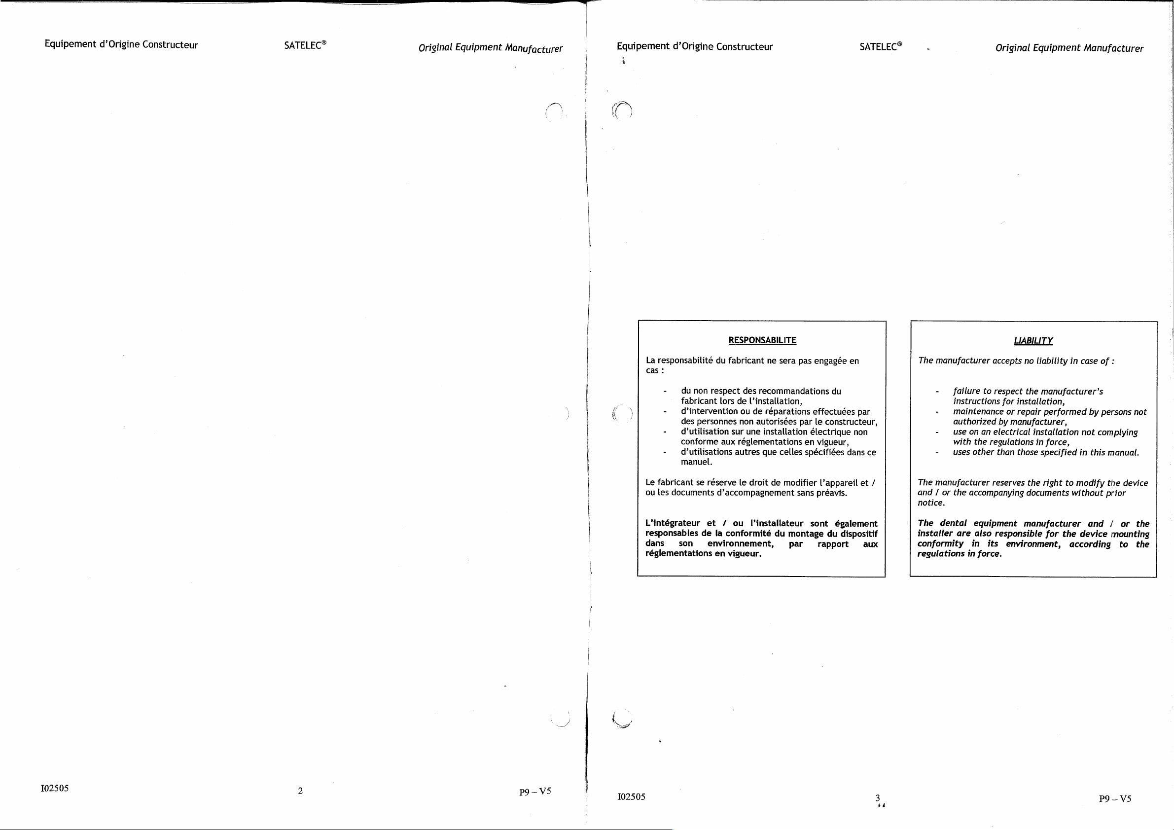
La
responsabilité
cas:
-
du
non
fabricant
-
d’intervention
des
-
d’utilisation
conforme
-
d’utilisations
manuel.
Le
fabricant
ou
les
documents
L’intégrateur
responsables
dans
réglementations
son
RESPONSABILITE
du
fabricant
respect
personnes
se
réserve
et / ou
de
environnement,
des
lors
de
ou
non
sur
aux
réglementations
autres
le
d'accompagnement
la
conformité
en
vigueur.
ne
sera
pas
recommandations
l’installation,
de
réparations
autorisées
une
installation
que
droit
l'installateur
celles
de
modifier
du
montage
par
par
sans
engagée
du
effectuées
le
constructeur,
électrique
en
vigueur,
spécifiées
l’appareil
préavis.
sont
également
du
rapport
en
par
non
dans
ce
et
/
dispositif
aux
The
manufacturer
-.
failure
instructions
-
maintenance
authorized
-
use
with
-
uses
The
manufacturer
and / or
notice.
The
installer
conformity
regulations
the
dental
are
accepts
to
respect
for
by
onan
electrical
the
regulations
other
than
reserves
accompanying
equipment
also
responsible
in
its
in
force.
LIABILITY
no
liability
the
manufacturer's
installation,
or
repair
performed
manufacturer,
installation
in
force,
those
specified
the
right
documents
manufacturer
for
environment,
in
case
by
not
in
this
to
modify
without
and / or
the
device
according
of
:
persons
complying
manual.
the
device
prior
mounting
to
not
the
the
102505
p9—V5
SE
102505
P9 — V5
Page 3
Equipement
1
About
2
Recommended
3
Before
This
These
MINILED
For
installation.
Before
instructions
each
starting,
You
Before
curing
See
d'Origine
Install
CURING
configuration,
Pozidrive
Needle
Routing
Wire
Wire
Voltmeter
Hex
Constructeur
detail
Tools
ensure
or
nose
cable
cutters
strippers
key
set
Begin
LIGHT
all
Phillips
pliers
beginning
light,
install
instructions
how
to
on
A-dec
follow
the
the
tools
head
the
installation
the
handpiece
provided
install
the
chairs.
steps
to
are
available:
screwdriver
of
tubing.
by
A-dec.
SATELEC
achieve
the
SATELEC®
the
Original
4
How
to
install
Find
the
configuration
instructions:
A-dec
A-dec
A-dec
A-dec
Instrumentation
Performer
Performer
Radius
Radius
Radius
12
O’clock
500
Delivery
500
Assistant’s
500
12
O’
clock
500
12
O’
clock
(545)
Assistant’s
Delivery
Assistant’s
Assistant’s
Delivery
System
Delivery
Equipment
below,
and
Manufacturer
follow
System
Instrumentation
Delivery
Assistant’s
Instrumentation
System
System
Instrumentation
Without
System
Cuspidor
4631
the
(541)
a
|
5
6
7
8
9
10
11
12
13
14
«tr
Equipement
à
A-dec
=
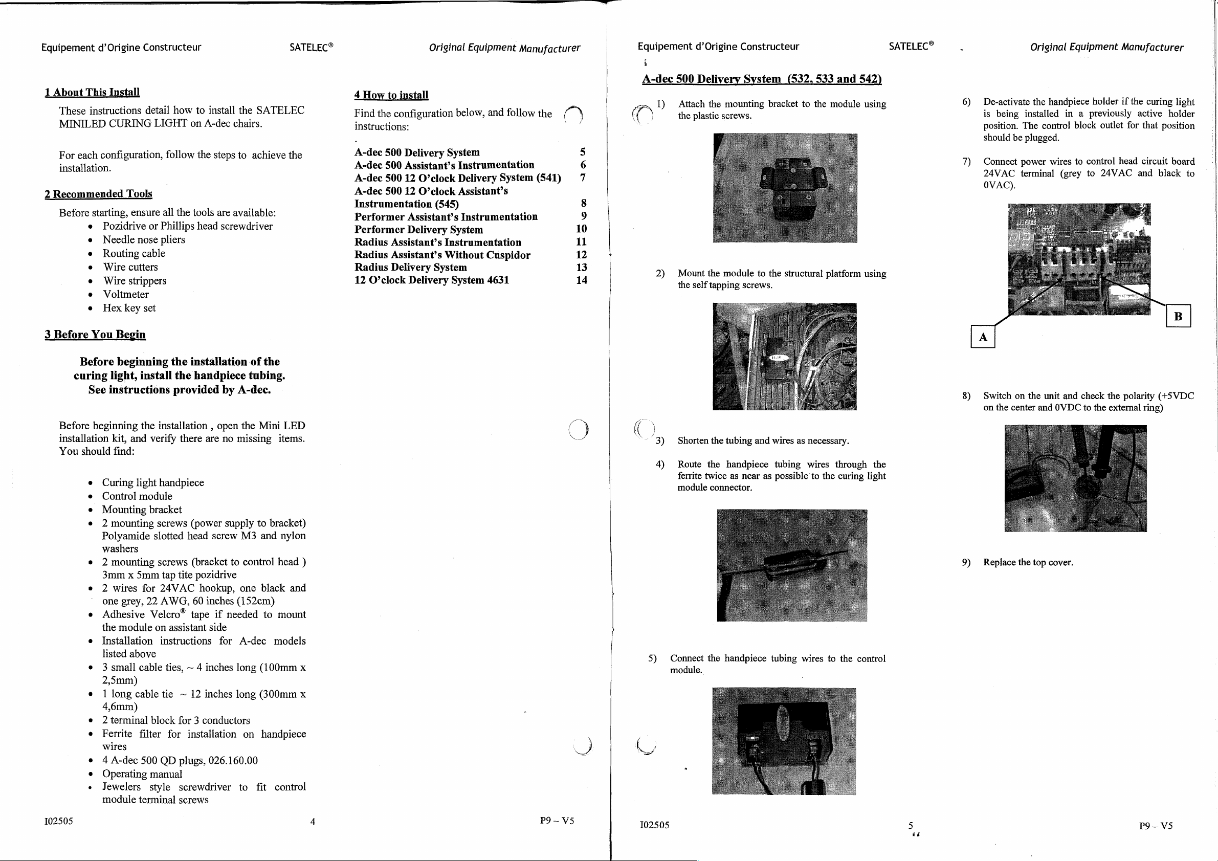
1)
2)
500
Attach
the
Mount
the
d’Origine
Delivery
the
mounting
plastic
screws.
the
module
self
tapping
Constructeur
System
screws.
bracket
to
the
(532,
structural
to
533
the
module
platform
and
542)
using
using
SATELEC®
-
6)
De-activate
is
position.
should
7)
Connect
24VAC
0VAO).
8)
Switch
on
being
be
the
center
Original
the
handpiece
installed
The
control
plugged.
power
terminal
on
the
unit
and
Equipment
holder
in a previously
block
outlet
wires
to
control
(grey
to
24VAC
and
check
OVDC
to
the
Manufacturer
if
the
curing
active
for
that
head
circuit
and
the
polarity
external
ring)
light
holder
position
board
black
to
(+SVDC
Before
installation
You
beginning
kit,
should
find:
Curing
Control
Mounting
2
mounting
Polyamide
washers
e 2 mounting
3mm x 5mm
e 2 wires
-
one
e
Adhesive
the
e
Installation
listed
e 3 small
2,5mm)
ο 1 long
4,6mm)
e 2 terminal
e
Ferrite
wires
e 4 A-dec
e
Operating
。
Jewelers
module
the
and
light
module
for
grey,
module
above
cable
cable
filter
500
terminal
installation , open
verify
there
are
handpiece
bracket
screws
slotted
screws
22
Velcro®
on
block
manual
style
(power
head
(bracket
tap
tite
pozidrive
24VAC
AWG,
hookup,
60
inches
tape
assistant
instructions
ties, ~ 4
tie ~ 12
for 3 conductors
for
QD
side
inches
inches
installation
plugs,
026.160.00
screwdriver
screws
no
supply
screw
to
if
needed
for
the
Mini
missing
to
M3
and
control
one
black
(152cm)
to
A-dec
long
(100mm
long
(300mm
on
handpiece
to
fit
LED
items.
bracket)
nylon
head
)
and
mount
models
x
x
control
5)
Shorten
Route
ferrite
module
Connect
module.
the
tubing
the
handpiece
twice
as
connector.
the
handpiece
and
near
wires
tubing
as
possible
tubing
as
necessary.
wires
to
the
wires
to
through
curing
the
control
the
light
9)
Replace
the
top
cover.
102505
4
P9 — VS
102505
P9—
tê
VS
Page 4

Equipement
A-dec
1)
2)
3)
500
Turn
Remove
connector
Remove
arm.
d’
Origine
Assistant’s
power
off
solids
from
the
tubing
Constructeur
Instrumentation
collector
the
support
link.
bracket
and
from
(551)
vacuum
the
assistant’s
pipe
7)
8)
the
Route
twice
ferrite
module
Connect
module.
Original
handpiece
near
as
connector.
the
handpiece
Equipment
tubing
possible
as
tubing
Manufacturer
around
wires
curing
the
to
wires
to
the
control
the
Yt
Equipement
i
A-dec
500
Turn
Do
arm
For
2)
"other."
for
instructions.
deactivate
Route
3)
side
d'Origine
12
O’Clock
power
off
assembly.
deluxe
Press
three
the
the
handpiece
support
touchpads,
seconds,
holder
arm.
Constructeur
Delivery
and
remove
program
and
hold
program
and
For
standard
position.
tubing
System
the
top
holder
and
follow
or
no
through
(541)
cover
position
A/B
buttons
on
screen
touchpads
the
doctor’s
of the
to
SATELEC®
6)
7)
8)
Connect
circuit
black
to
Shorten
Route
ferrite
twice
module
Original
the
power
board
24VAC
OVAC).
the
tubing
the
handpiece
as
near
connector.
Equipment
wires
to
terminal
and
wires
tubing
as
possible
Manufacturer
the
delivery
(grey
to
as
necessary.
wires
through
to
the
curing
system
24VAC,
the
light
4)
5)
Use
stringer
link,
down
/
water
Attach
cable
tie.
to
route
the
chair
manifold.
the
control
the
lift
arm
module
wires
and
to
the
through
under
lift
arm
the
support
the
chair
base with
air
9)
10)
11)
Connect
24VAC
OVAC).
Secure
supply
Switch
on
the
power
terminal
the
tubing
with
the
on
the
center
screw
unit
and
wires
(grey
strain
and
OVDC
to
relief
from
check
to
the
to
the
the
the
chair
circuit
24VAC,
string
to
kit.
polarity
external
p
blac,
the
power
(+5VDC
ring).
|
LA
+
TO
Co
4)
5)
Attach
using
Mount
using
the
mounting
the
plastic
the
module
the self
screws.
tapping
bracket
to
the
screws.
to
the
control
control
module
central
frame
9)
10)
11)
Connect
module.
Attach
cable
tie.
Switch
on
the
center
ferrite
on
the
handpiece
to
the
unit
and
the
and
OV
tubing
control
check
DC
to
wires
center
the
the
external
to
the
frame
polarity
(+5VDC
ring)
control
using
6)
102505
Shorten
the
tubing
and
wires
as
necessary.
12)
Switch
vacuum
off
and
replace
pipe.
solids
collector
P9 一 V5
and
102505
12)
Replace
34
the
top
cover
of
the
arm
P9—
assembly.
VS
Page 5

Equipement
A-dec
545
1)
2)
3)
500
Turn
Remove
and
Route
tubing
d'Origine
12
power
remove
the
hole.
Constructeur
O’Clock
off
the
two
it.
handpiece
Assistant’s
screws
holding
tubing
Instrumentation
the
work
surface
through
the
syringe
SATELEC®
7)
8)
Attach
work
surface
Secure
screw
Original
the
control
the
from
the
module
support
tubing
kit.
Equipment
to
the
housing
strain
relief
Manufacturer
inside
wall
using
Velcro.
string
with
athe
y
/
Equipement
‘Performer
Turn
2)
Install
3)
Open
connector.
4)
Cut
connector
d'Origine
Constructeur
Assistant’s
power
off
and
handpiece
the
junction
back
wire
insulation
side.
Instrumentation
remove
tubing.
box
seat
and
disconnect
five
inches
upholstery.
on
the
the
white
male
SATELEC®
Adjust
10)
necessary
module.
Adjust
11)
necessary
module.
Attach
12)
junction
Original
the
length
and
the
length
and
the
control
box
with
Equipment
of
the
handpiece
connect
of
the
handpiece
connect
module
Velcro.
Manufacturer
them
to
them
to
to
the
tubing
the
tubing
the
bottom
wires
as
control
wires
as
control
of
the
4)
5)
6)
Adjust
wires
Route
the
length
as
necessary
the
wires
of
the
through
handpiece
the
ferrite
tubing
twice
and
9)
10)
Switch
on
the
Switch
on
the
center
off
the
unit
and
unit
and
OVDC
and
check
the
to
the
replace
polarity
external
work
surface
(+5
ring).
5)
Cut
the
black
and grey
Ya
inch.
6)
Install
the
black
grey
wires
to
the
2
7)
)
)
°
-
8)
9)
Connect
control
Shorten
Route
ferrite
module
the
black
module
the
tubing
the
handpiece
twice
as
connector.
wires
other
and
and
near
y
power
to
terminal
and
the
terminal
wires
tubing
as
possible
one
grey
wires,
terminal
strip.
power
strip.
if
needed.
wires
to
the
and
strip,
wires
around
curing
strip
and
to
back
the
the
the
light
13)
14)
Switch
on
the
Switch
on
the
center
off
and
unit
and
close
and
OVDC
the
check
the
to
the
junction
polarity
external
box.
(+5VDC
ring).
102505
8
P9 — VS
102505
P9 — VS
Page 6

Equipement
Performer
Turn
1)
Install
2)
Attach
3)
and
Shorten
4)
d'Origine
Delivery
power
off
the
handpiece
Velcro
connect
the
the
tubing
Constructeur
System
and
remove
onto
power
and
the
tubing.
the
drive
wires
wires
to
if
covers.
air
pressure
the
terminal
needed.
gauge
strip.
SATELEC®
8)
9)
Attach
pressure
Switch
on
the
the
on
center
Original
control
gauge
with
the
unit
and
Equipment
module
Velcro.
and
check
OVDC
to
Manufacturer
on
top
of
the
polarity
the
external
the
(+5
ring).
drive
VDC
air
VU
|
Equipement
i
‘Radius
TN
1)
2)
3)
4)
d’Origine
Assistant’s
Turn
power
cover.
Install
the
handpiece
Shorten
Route
as
connector.
the
near
the
light
as
tubing
Constructeur
Instrumentation
off
and
remove
tubing.
and
wires
cable
wires
around
possible
to
the
with
the
cuspidor
as
necessary.
the
curing
housing
ferrite
light
SATELEC®
Cuspidor
twice
module
。
8)
Switch
on
the
Original
on
the
center
unit
and
OVDC
Equipment
and
check
to
the
Manufacturer
the
polarity
external
ring)
(+5VDC
5)
6)
7)
Secure
from
the
Route
ferrite
twice
module
Connect
module.
the
tubing
kit.
the
handpiece
as
near
connector.
the
handpiece
strain
as
relief string
tubing
possible
tubing
wires
to
the
wires
with
around
curing
to
the
the
screw
the
light
control
10)
Switch
off
and
replace
the
covers.
一
,
y
5)
Connect
|
|
(
-
|
6)
Strip
control
the
back
the
module.
wires
power
to
the
control
wires
and
module
connect
them
to
the
9)
Turn
power
соуег.
off
and
replace
the
cuspidor
housing
102505
10
P9
V5
一
Po,
LA
7)
a
102505
Attach
mounting
the
control
bracket.
module
with
zip
tie
to
the
11
+4
P9
一
V5
Page 7

Equipement
Radius
Assistant’s
Cuspidor
1)
Turn
2)
Install
3)
Route
as
connector.
d’Origine
power
handpiece
the light
near
Constructeur
Instrumentation
off
and
remove
tubing.
cable
wires
as
possible
to
covers.
around
the
curing
without
the
ferrite
light
SATELEC®
twice
module
7)
8)
Connect
Attach
chair
the
base.
Original
wires
to
control
Equipment
control
module
module
Manufacturer
with
Velcro
to
(
\
the
Eguipement
Radius
O
1)
2)
3)
d'Origine
Delivery
Turn
power
Install
handpiece
Route
ferrite
module
the
twice
connector.
Constructeur
System
off
and
remove
tubing.
handpiece
as
near
as
(2122
and
covers.
tubing
possible
2152)
wires
to
the
around
curing
SATELEC®
the
light
.
7)
Switch
on
the
8)
Turn
on
center
power
Original
the
unit
and
OVDC
off
and
Equipment
and
check
to
the
replace
covers.
Manufacturer
the
polarity
external
ring).
(+5VDC
4)
5)
Connect
power
supply
Route
the
chair
base
the
power
black
and
located
wires
in
grey
the
from
power
floor
the
box
floor
wires
box
to
to
the
the
9)
Switch
on
the
on
the
center
unit
and
and
OVDC
check
to
the
Control
module
the
polarity
external
(+5VDC
ring)
4)
Connect
the
wires
to
the
control
module.
m
eee
ο
i
5)
6)
Mount
using
Connect
the
module
Velcro.
the
power
to
wires
the
to
control
the
terminal
head
platform
strip.
Power
6)
102505
|
wires
Adjust
power
the
length
wires
of
handpiece
as
necessary.
Power
tubing
wires
wires
and
12
10)
Turn
power
off
and
replace
the
covers.
P9 一 V5
NL
j
102505
VOLTS
AC
13
tá
P9 — V5
Page 8
Equipement
12
O’Clock
Note: A 25
curing
1)
2)
3)
d’Origine
Watt
light.
Turn
Install
Connect
OVACand
Delivery
power
off.
power
handpiece
the
power
grey
Constructeur
System
supply
tubing.
cable
to
24AC).
4631
must
to
be
installed
the
power
to
operate
supply
SATELEC®
(Black
the
to
8)
9)
10)
Attach
with
Velcro.
Switch
on
the
Turn
power
Original
the
control
on
the
center
and
off
Equipment
unit
and
OVDC
and
module
check
to
replace
Manufacturer
to
the
control
the
polarity
the
external
covers.
ce
n
(*SVDC
ring).
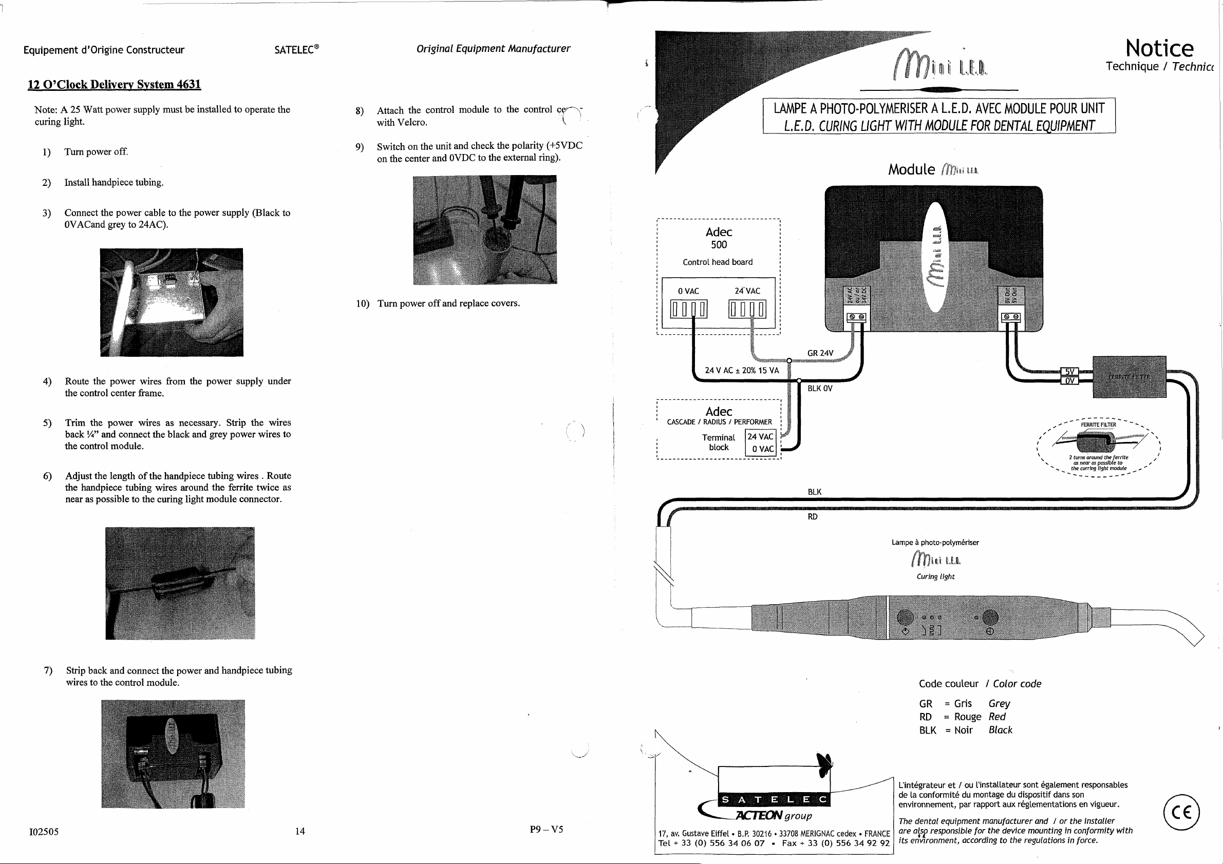
Control
head
board
0
VAC
(0g
24
VAC
MON
LAMPE A PHOTO-POLYMERISER A L.E.D.
L.E.D.
CURING
LIGHT
WITH
MODULE
AVEC
FOR
DENTAL
MODULE
EQUIPMENT
POUR
Notice
Technigue / Technic
UNIT
4)
5)
6)
Route
the
control
Trim
back
the
control
Adjust
the
handpiece
near
as
the
power
center
the
power
Ys”
and
module.
the
length
possible
wires
frame.
wires
connect
of
tubing
to
the
from
as
the
black
the
handpiece
wires
curing
the
power
necessary.
and
grey
tubing
around
light
the
module
supply
Strip
the
power
wires
wires . Route
ferrite
twice
connector.
under
wires
to
as
24V
AC + 20%
k
Adec
“CASCADE / RADIUS / PERFORMER!
,
Terminal
block | O
|24
15
VAC|
yAC|
VA
i
#
mm
BLK
RD
Lampe a phota-polymériser
[Misi
Curing
vee
light
-
7”
4 I
<
~~
FERRITEFILTER
2
turns
around
as
near
as
possible
fhecurring
light
一 ~ 一 一 一 一 一 一 一 一
“~~、
139
Mr
se
the
ferrite
to
module > ^
~
~
ヽ
2
΄
x
\
了
7)
102505
Strip
wires
back
to
the
and
connect
control
the
module.
power
and
handpiece
tubing
14
P9
—
V5
17,
av.
Tel + 33
Gustave
Eiffel « B.P.
(0)
556
ACTEON
30216 » 33708
34 06
07 ㆍ Fax + 33
group
MERIGNAC
cedex + FRANCE | are
(0)
556
34
92
92
Code
couleur / Color
GR = Gris
RD
=
BLK = Noir
L'intégrateur
de
la
environnement,
The
dental
also
its
environment,
et / ou
conformité
equipment
responsible
Rouge
l'installateur
du
montage
par
rapport
manufacturer
for
according
Grey
Red
Black
aux
the
device
to
du
the
code
sont
également
dispositif
réglementations
dans
and / or
mounting
regulations
in
son
the
conformity
in
responsables
en
vigueur.
installer
force.
with
Page 9

.
SCHEMA
ED:
AI
SINNI
PR
YAKA
mange
cannes
ee
je
enr
F02505
tt.
an,
js
PARTS
QTE|
DESIGNATION
1
Module
1
Support
2
Vis
2
Vis
1
Bande
1
Bande
TCF
taptite
LIST
Mini
LED
Newtron
M3x6
M3
x5
Velcro
crochet
Velcro
boucle
OEM
kit
A-dec | Mounting
Mini
Plastic
‘3mm x 5mm
Hooks
Loops
DESCRIPTION
LED
curing
light
bracket
screw
TCF
M3x6
taptite
pozidrive
adhesive
adhesive
Velcro
Velcro
module
tape
tape
Silicone
Mini
LED
Mini
L.E.D.
Light
Shield
Jewelers
A-dec
500
Terminal
Cable
tie
Cable
tie
Ferrite
filter
UL
grey
Handpiece
style
(100 x 2.5mm)
wire
1
Cordon
silicone
1
Guide
optique
Mini
LED
1
Piece à main
1
Ecran
1
Tournevis
4
Bouchon
2 | Bloc
3
Collier
1
Collier
1 | Ferrite
1 | Fil
gris
de
protection
laiton
de
jonction
Tyrap
Tyrap
UL
Jauge
Mini
LED
22
tubing
light
guide
OEM
handpiece
screwdriver
OD
plugs
block
(300 x 4.6mm)
AWG22
document.
contractual
Non
-
contractuel
non
1
‘|
Fil
gris
noir
Jauge
22
1 | Notice
1 | Guide
Mini
LED
d’
installation Installation
UL
Mini
black
LED
wire
AWG22
notice
guide
Document
-
V5
-
P9
-
102505
 Loading...