

Page 1
A-dec DV Dry Vacuum Service Guide
A-dec DV Dry Vacuum
Service Guide
Contents
Overview .......................................................... 2
Copyright and Regulatory Information ....................................... 2
Requirements ..................................................... 3
Description of Operation ......................................................3
Vacuum Models ..................................................................3
Site Specications and Sizing Information ..................................4
HVAC Requirements .............................................................5
Operate ............................................................ 6
Turn On/Turn Off Power ........................................................6
Master Power Switch ............................................................. 6
LED Push-Button Controls ....................................................... 6
Optional Smart Shield Touchscreen Controls ................................ 6
Vacuum Gauge and Operation................................................. 7
Vacuum Gauge .....................................................................7
Vacuum Startup and Normal Operation ........................................7
Separator Tank Drain and Washdown Cycles ..................................7
Smart Shield Touchscreen Controls ..........................................8
Vacuum Startup and Shutdown ................................................. 8
Vacuum System Status Icons .................................................... 9
Mechanical Room Controls....................................................11
Mechanical Room 24 V Competitive Cross Reference ........................ 13
Flow Diagram ..................................................... 14
Components ...................................................... 15
Wiring Diagram ................................................... 17
Fuse Identication ............................................................ 18
Maintain/Troubleshoot .......................................... 19
Regular Maintenance Tasks .................................................. 19
Annual Check Valve Change ..................................................21
Troubleshooting Tasks ........................................................ 22
Status Lights ................................................................... 23
Circuit Board Electrical Test Locations .................................... 24
Initial Startup Checklist ...................................................... 25
86.0897.00 Rev A
1
Page 2

A-dec DV Dry Vacuum Service Guide Overview
Overview
Copyright and Regulatory Information
Copyright
© 2021 A-dec Inc. All rights reserved.
A-dec, Inc. makes no warranty of any kind with regard to this material,
including, but not limited to, the implied warranties of merchantability and
fitness for a particular purpose. A-dec, Inc. shall not be held liable for any
errors contained herein or any consequential or other damages concerning
the furnishing, performance or use of this material. The information in this
document is subject to change without notice. If you find any problems in
the documentation, please report them to us in writing. A-dec, Inc. does not
warrant that this document is error-free.
No part of this document may be copied, reproduced, altered, or transmitted
in any form or by any means, electronic or mechanical, including
photocopying, recording, or by any information storage and retrieval system,
without prior written permission from A-dec, Inc.
Trademarks and Additional Intellectual Property Rights
A-dec, the A-dec logo, A-dec Inspire, Cascade, Century Plus, Continental,
Decade, ICX, ICV, Performer, Preference, Preference Collection,
Preference ICC, Radius, and reliablecreativesolutions are trademarks
of A-dec, Inc. and are registered in the United States and other countries.
A-dec 500, A-dec 400, A-dec 300, A-dec 200, and EasyFlex are also trademarks
of A-dec, Inc. None of the trademarks or trade names in this document may
be reproduced, copied, or manipulated in any manner without the express,
written approval of the trademark owner.
Regulatory Information and Warranty
For required regulatory information and the A-dec warranty, see
the Regulatory Information, Specifications, and Warranty document
(p/n 86.0221.00) available in the Resource Center at www.a-dec.com.
Product Service
Product service is available through your local authorized A-dec dealer.
For service information, or to locate an authorized dealer, contact A-dec at
1.800.547.1883 in the USA or visit www.a-dec.com.
Product Models and Versions Covered in This Document
Models Versions
DV5/DV7
DV10/DV12
n/a Dry Vacuum
Description
Certain touchpad symbols and icons are proprietary to A-dec, Inc. Any use
of these symbols or icons, in whole or in part, without the express written
consent of A-dec, Inc., is strictly prohibited.
86.0897.00 Rev A
2
Page 3
A-dec DV Dry Vacuum Service Guide Requirements
Requirements
Description of Operation
• The dry vacuum system has a variable speed vacuum pump that reduces electrical consumption. The integrated separator tank and firmware allow for fully
automated operation.
• The vacuum creation and operation is free from water and oil.
• The vacuum motor is controlled by a vacuum sensor connected to the separator tank. The speed of the motor will increase or decrease to maintain the pre-set
vacuum level.
• The vacuum system has an automated tank washdown maintenance cycle that starts within 1 minute of the system being turned off. The washdown solenoid
opens to allow fresh water to spray into the tank, rinsing the tank free from debris. This cycle runs for approximately 1 minute.
• The integrated separation tank has been designed to collect the fluids evacuated during a normal operating day. If an excessive amount of fluids is collected,
the float switch in the separator will stop the vacuum in order for the tank to automatically drain. This process takes about 10 seconds. The vacuum will
automatically restart after the drain cycle.
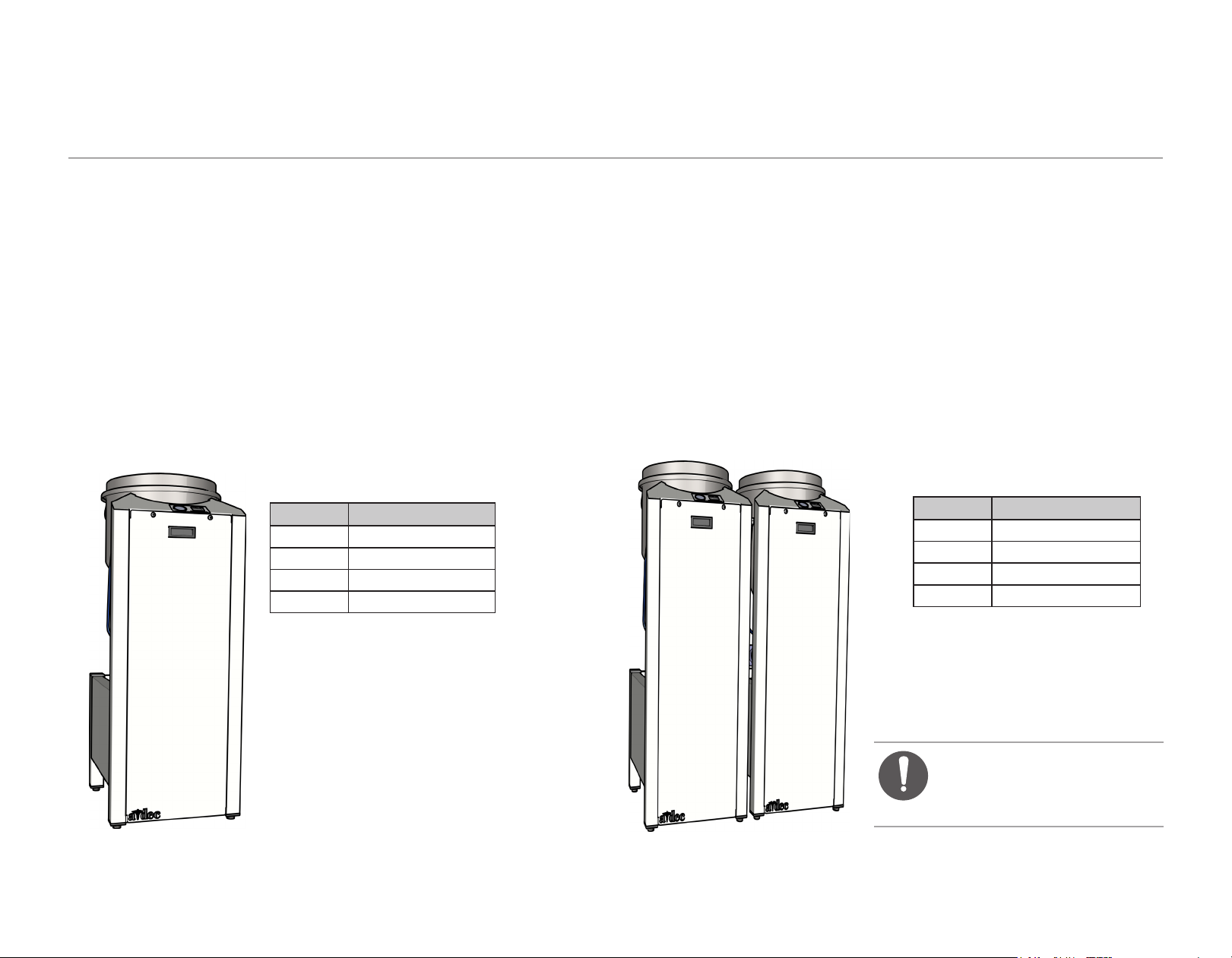
Vacuum Models
86.0897.00 Rev A
Single Vacuum Models
Model Number of Users
DV5 1 - 5
DV7 5 -7
DV10 7 - 10
DV12 10 - 12
Tandem Vacuum Models
Model Number of Users
DV5t 7 - 10
DV7t 10 - 14
DV10t 14 - 20
DV12t 20 - 24
NOTE Three or more vacuums
can be combined. Contact
A-dec Customer Service for
information.
3
Page 4
A-dec DV Dry Vacuum Service Guide Requirements
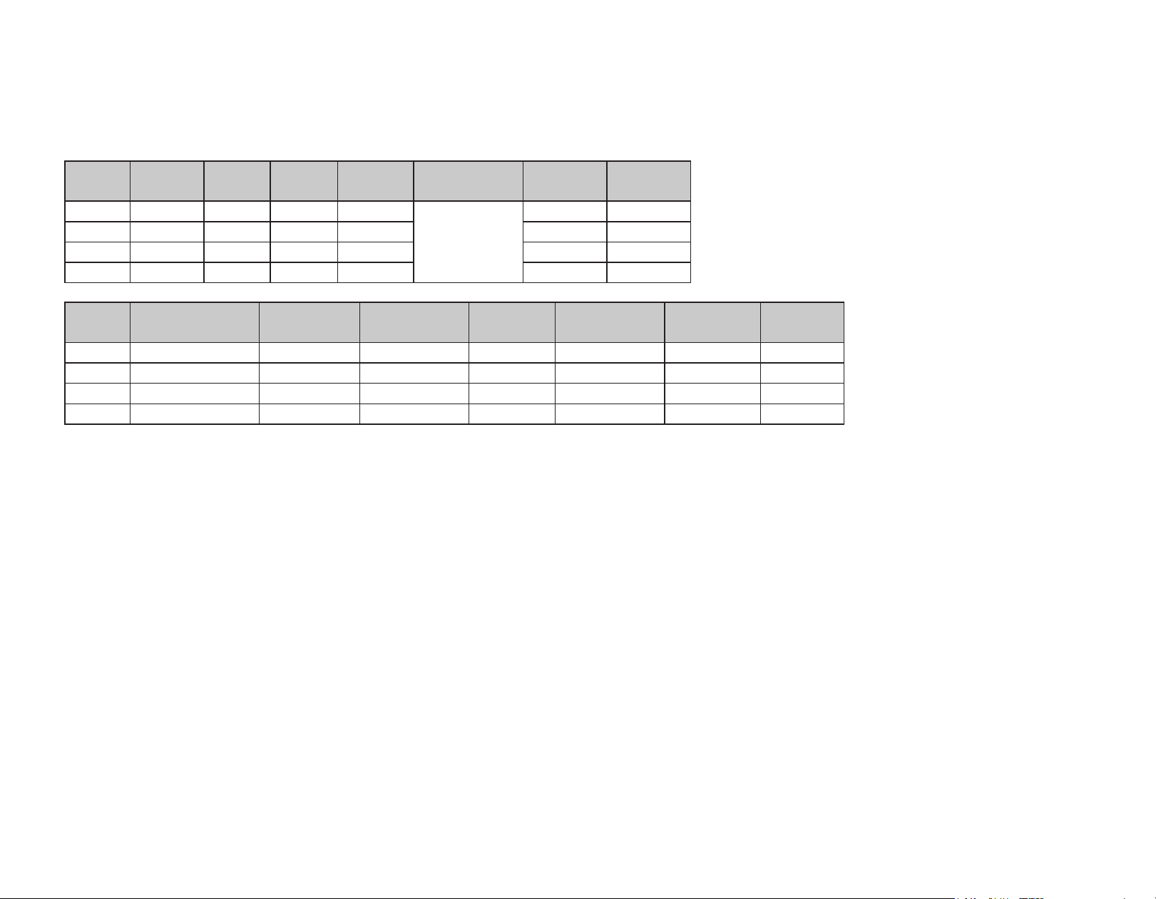
Site Specifications and Sizing Information
Model Max
Users
DV5 5 35 10 2.3
DV7 7 57 10 3.0 20.6 30
DV10 10 74 10 3.4 22.0 30
DV12 12 92 10 4.1 24.0 30
Model Dims - WxDxH
Installed
DV5 18 x 19.5 x 48.5" 152 lbs 24 x 31 x 55" 183 62.8 57. 4 5,700
DV7 18 x 19.5 x 48.5" 152 lbs 24 x 31 x 55" 183 70.0 57. 4 6,800
DV10 18 x 19.5 x 48.5" 191 lbs 24 x 31 x 55" 214 63.2 58.3 8,700
DV12 18 x 19.5 x 48.5" 191 lbs 24 x 31 x 55" 214 70.5 58.3 10,436
CFM
@8"Hg
Set
"Hg
Weight
Installed
Total HP Voltage
Range
200-240 VAC
Dims - WxDxH
Packaged
Weight
Packaged
Amps
Max
14.1 20
Breaker
Size
Sound db(A)
Max
Sound db(A)
Average
BTU/Hr
Max
86.0897.00 Rev A
4
Page 5
A-dec DV Dry Vacuum Service Guide Requirements
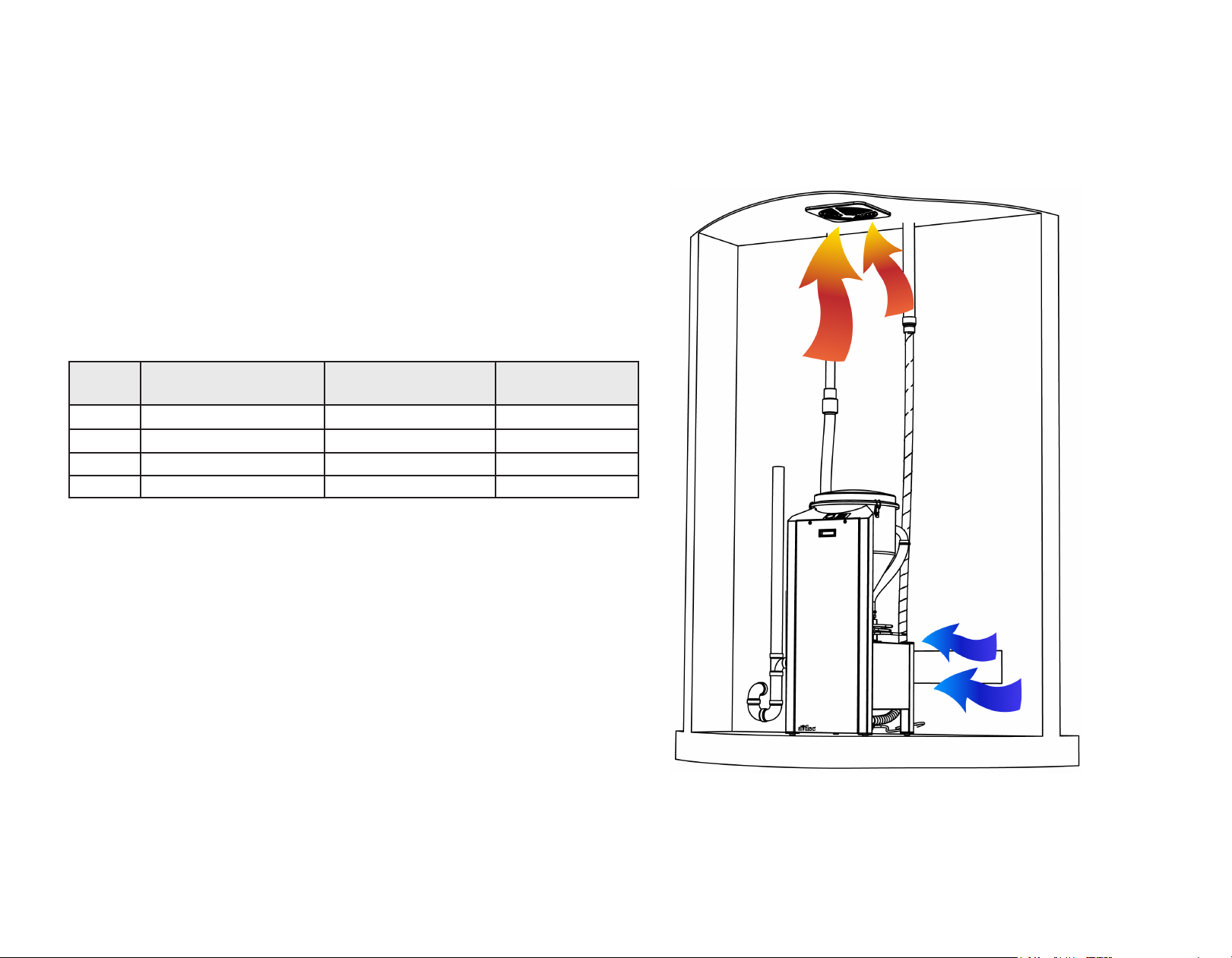
HVAC Requirements
Adequate cooling air is required. All vacuum models are installed and
operated in a thermostatically or otherwise stable ambient temperature
environment. Forced air and HVAC input are recommended for use in
addition to an exhaust fan if normal ambient temperatures vary from
specified operating temperature range.
The operating temperature range of the vacuum is 40º F to 104º F or 4.4 to
40º C.
Vacuum life is directly affected by the operating temperature.
Model
DV5 5,700 1,425 200
DV7 6,800 1,700 230
DV10 8,700 2,175 350
DV12 10,346 2,175 400
* Based on 80º F/27º C cooling air available and 100º F/38º C maximum mechanical room
temperature. This does not account for overall mechanical room size and additional heat
sources. Consult an HVAC specialist for proper temperature range.
Maximum Heat
Rejection (BTU/Hr)
Average Heat
Rejection (BTU/Hr)
CFM Cooling Fan *
86.0897.00 Rev A
5
Page 6
A-dec DV Dry Vacuum Service Guide Operate
Operate
Turn On/Turn Off Power
NOTE If you turn off the vacuum unit for long periods of non-use,
like an extended office shutdown, ensure that the power remains
connected. The vacuum will automatically turn on, momentarily,
every 12 hours to prevent components from seizing. This also helps
extend the life of the motor.
Master
Power
LED Push-Button Control
(single-button)
Switch
LED Push-Button Control
(four-button)
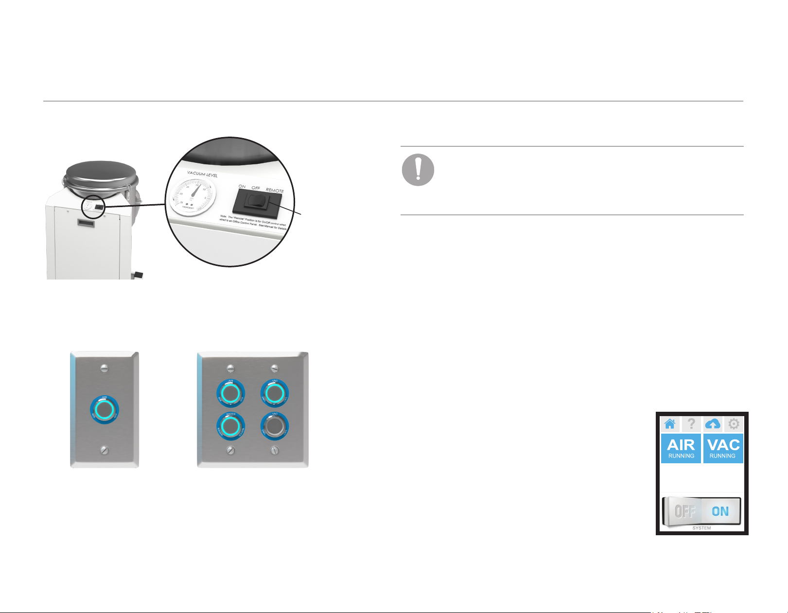
Master Power Switch
The master power switch turns the vacuum on or off. It also overrides the
other remote power functions. If your vacuum is connected to remote LED
push-button controls or a Smart Shield touchscreen, this switch should be in
the REMOTE position.
LED Push-Button Controls
If you have LED push-button controls, press the button once to turn the
vacuum unit on or off. Blue LED lighting indicates that the vacuum is on. If
the LED does not illuminate, check and verify that the master power switch on
the vacuum is in the REMOTE position.
86.0897.00 Rev A
Optional Smart Shield Touchscreen Controls
For congurations with the Smart Shield
touchscreen, use the power switch icon at the
bottom of the screen or tap the VAC icon to turn
the vacuum unit on or off. If the Smart Shield does
not operate, check and verify that the master power
switch on the vacuum is in the REMOTE position.
For more information on the touchscreen, see
“Smart Shield Touchscreen Controls” on page 8.
4
6
Page 7
A-dec DV Dry Vacuum Service Guide Operate
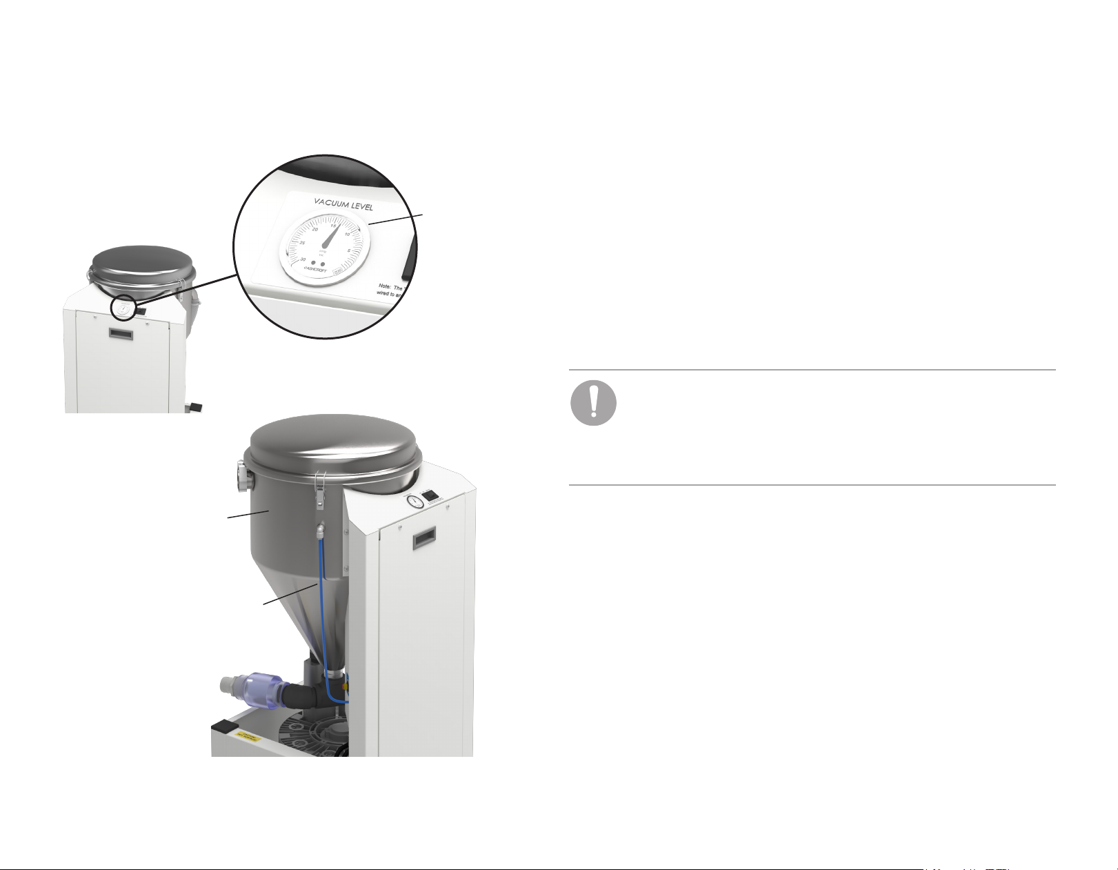
Vacuum Gauge and Operation
Vacuum Gauge
The vacuum gauge is located next to the master power switch on the top panel
Vacuum
Gauge
of the vacuum. This gauge provides a real-time level of the negative pressure
inside the separator tank. The DV dry vacuum is factory preset to maintain
10 inHg (34 kPa) during normal operation.
Vacuum Startup and Normal Operation
At initial startup, the vacuum motor runs until the system reaches the factory
preset of 10 inHg (34 kPa). As vacuum instruments are opened and closed, the
motor rpm will increase or decrease (depending on demand) to maintain that
level.
NOTE You may hear the vacuum motor frequently speeding up
or slowing down as it compensates for various levels of demand.
This is normal. However, if the motor does not slow down after
all vacuum instruments are closed, or if your system is unable to
consistently maintain 10 inHg (34 kPa), see “Troubleshooting Tasks”
on page 22 or contact A-dec Customer Service.
86.0897.00 Rev A
Separator
Tank
Washdown
Waterline
Separator Tank Drain and Washdown Cycles
The vacuum removes liquid from the air and collects it in the separator tank.
When more than 10 gallons (38 L) are collected, a float switch in the tank stops
the vacuum and drains the tank. Once the water level drops and the float
switch turns off, the vacuum will turn back on in about 10 seconds.
To manually initiate the drain and washdown cycles, you must turn off the
vacuum. Combined, both cycles take less than 2 minutes. A-dec recommends
that you turn off the vacuum to activate this process at least once a day. For
more information, see “Regular Maintenance Tasks” on page 19.
7
Page 8
A-dec DV Dry Vacuum Service Guide Operate
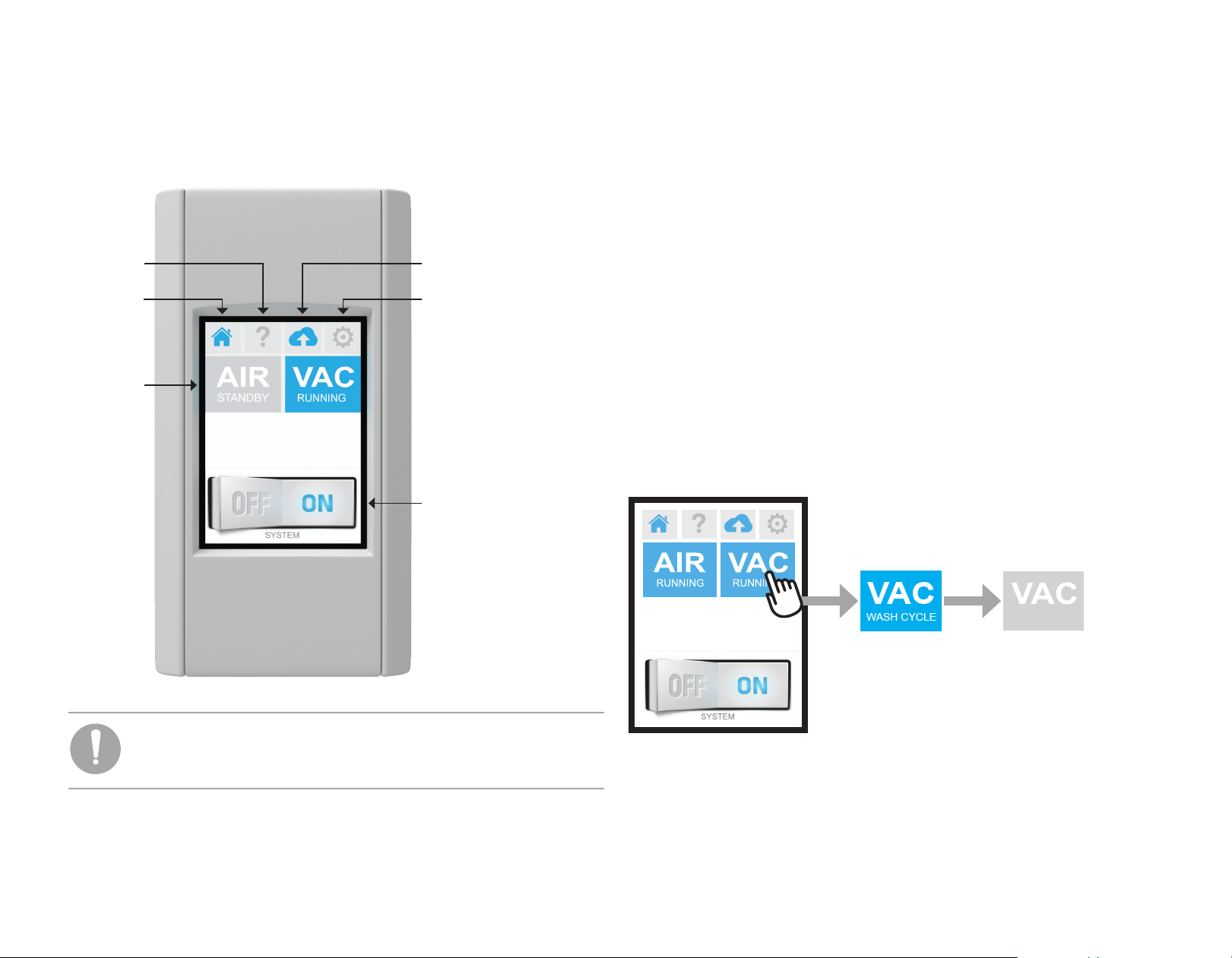
Smart Shield Touchscreen Controls
The optional Smart Shield touchscreen provides power control and system
status of your mechanical room equipment.
Service
Contact
Information
Home
System
Status
Icons
Remote Monitoring
Status
Software Version
and Reset
Power Switch
Tap the on/off switch icon at the bottom of the screen to turn on or turn off
all connected equipment at the same time. Tap the blue system status icons to
turn on or turn off individual equipment. These status icons also dynamically
change according to the operational state of the equipment.
Vacuum Startup and Shutdown
When you turn on the vacuum system, Smart Shield displays the
VAC RUNNING icon. When you tap the VAC RUNNING icon, the VAC OFF
icon appears, indicating the start of the separator tank drain cycle. Once the
drain cycle is complete, the VAC WASH CYCLE icon appears, indicating the
start of the washdown cycle. After that cycle is complete, the VAC OFF icon
reappears.
Vacuum Shutdown
(Tap to Initiate)
4
OFF
NOTE If the Smart Shield does not operate, check and verify that
the master power switch on the vacuum is in the REMOTE position.
For more information, see “Troubleshooting Tasks” on page 22.
86.0897.00 Rev A
8
Page 9

A-dec DV Dry Vacuum Service Guide Operate
MANUAL
MANUAL
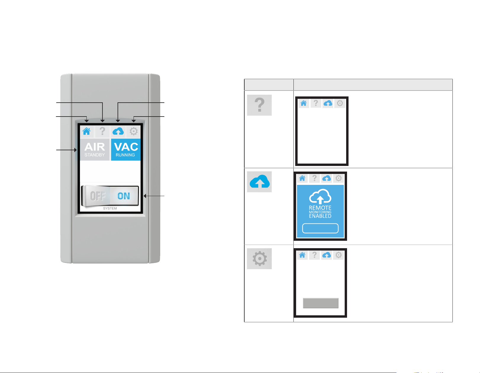
Smart Shield Touchscreen Controls (continued)
Vacuum System Status Icons
Service
Contact
Information
Home
System
Status Icons
(Tap to turn
equipment
on or off
individually.)
Remote Monitoring
Status
Software Version
and Reset
Power Switch
(Tap to turn all
attached equipment
on or off at the
same time.)
Icon State/Status
Displays during initial system startup and normal
operation mode.
“Manual” appears on status icons when the master
power switch on the vacuum is in the ON or OFF
position. To control power through the Smart Shield
touchscreen, ensure that the master power switch on
the vacuum is in the REMOTE position.
Displays when the vacuum is turned off from the Smart
Shield touchscreen controls.
OFF
Displays after the vacuum is turned off and the drain
cycle is complete.
Displays when the annual maintenance interval is
reached. This caution/reminder is reset whenever
power to the system is disconnected.
Displays when there is a fault in the system. Contact
A-dec Customer Service.
NOTE If additional warning icons appear on your screen and are
not shown here, contact customer service for more information.
86.0897.00 Rev A
9
Page 10
A-dec DV Dry Vacuum Service Guide Operate
Smart Shield Touchscreen Controls (continued)
Additional Smart Shield Functions
Service
Contact
Information
Home
System
Status
Icons
Remote Monitoring
Status
Software Version
and Reset
Power Switch
Icon State/Status
Q uestions?
1-800-547-1883
PRESS HERE TO
REQUEST SERVICE
Software V ersion
20180309
Displays contact information that will
route you to A-dec, Inc.
Displays your status as enabled if you
are registered with the remote
monitoring service. For questions,
contact A-dec Customer Service.
Displays software version. The reset
button turns off the screen, reboots the
software, and reloads the equipment
status. You can use RESET during
specic faults with the equipment. For
more information, see “Troubleshooting
Tasks” on page 22 .
86.0897.00 Rev A
RESET
10
Page 11

A-dec DV Dry Vacuum Service Guide Operate
Mechanical Room Controls
48 V Power Supply
with 8' Cord
86.0897.00 Rev A
Internet/LAN
Compressor,
Vacuum,
Smart Shield Touchscreen
Water Valve, or
NOTE The firmware in the smart hub was updated in March 2020
to include a dedicated port for the touchscreen.
Smart Hub Extender
11
Page 12
A-dec DV Dry Vacuum Service Guide Operate
Mechanical Room Controls (continued)
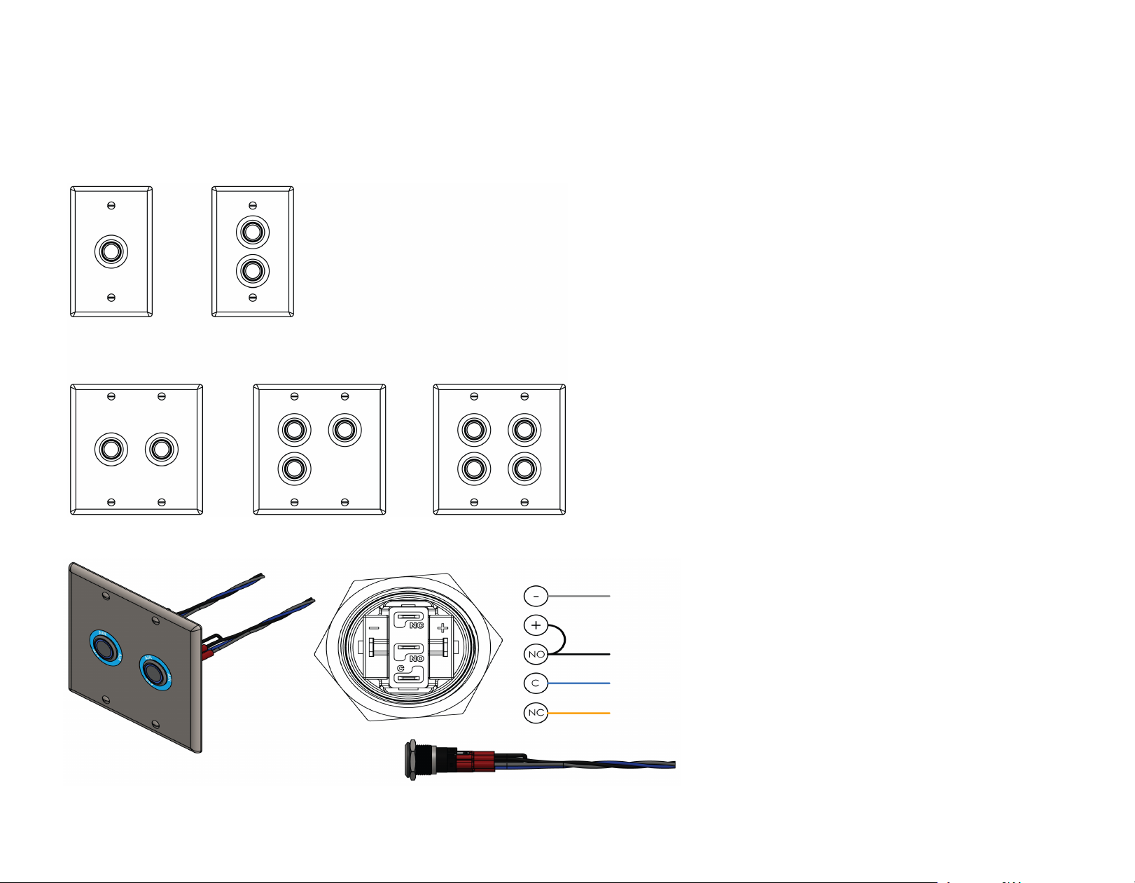
LED Push-Button Controls
86.0897.00 Rev A
Gray
Black - Run Signal
Blue - 24 V Power
Orange - Stop/Close (optional)
12
Page 13
A-dec DV Dry Vacuum Service Guide Operate
Mechanical Room Controls (continued)
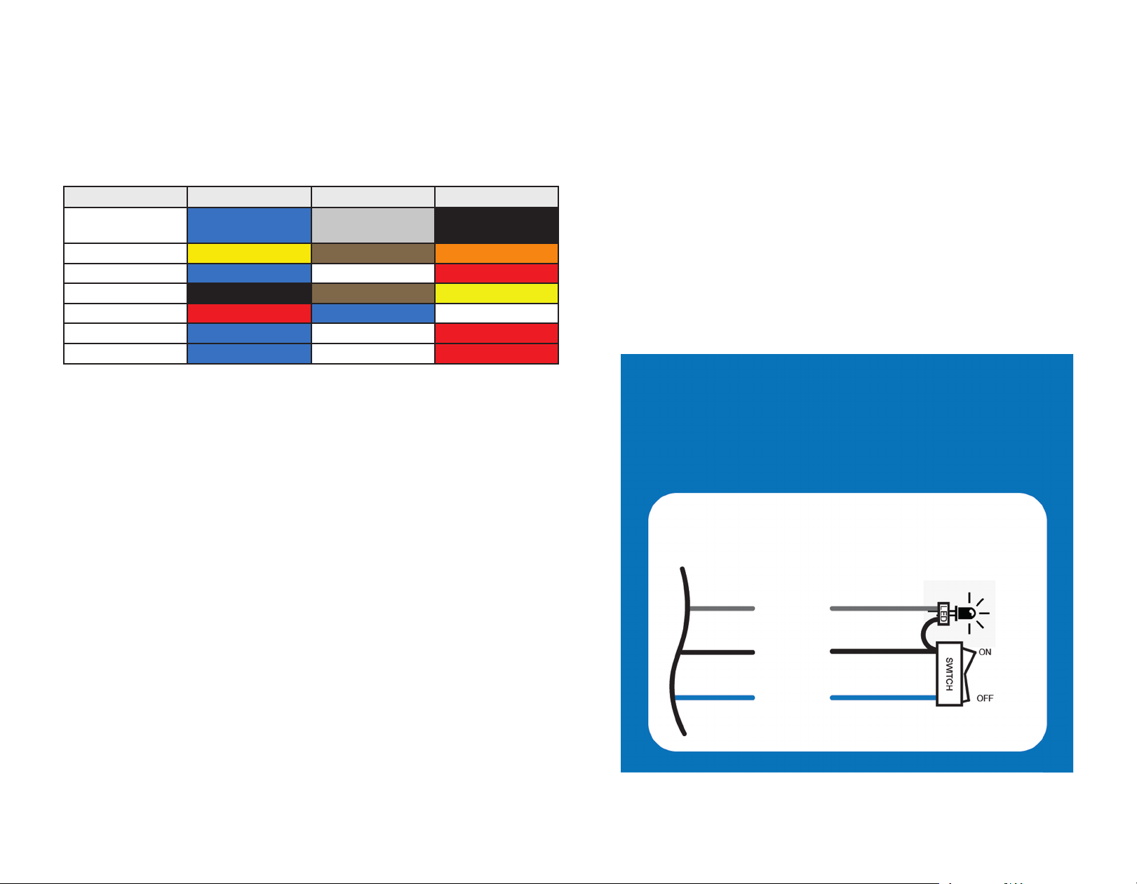
Mechanical Room 24 V Competitive Cross Reference
Mtg/Wire A B (Light) C
A-dec Blue
+ 24 VDC
AirTechniques Yellow Brown Orange
Midmark Blue White Red
Dental EZ Black Brown Yellow
Matrix Red Blue White
Apollo Blue White Red
Tech West Blue White Red
Gray
-Lamp
Black
Run Signal
Remote Panel 24 VAC Wiring
Do Not Tie Together
86.0897.00 Rev A
Remote Panel 24 VAC Wiring
-Light
Run
+24 ~
80 mA
Max
13
Page 14

A-dec DV Dry Vacuum Service Guide Flow Diagram
Flow Diagram
Roof Exhaust
Vent
Exhaust Hose
Separator Tank Filter
Airflow Coming from Operatories
PVC
86.0897.00 Rev A
Clear Inspection
Hose
Intake Hose
Washdown Water Line Inlet
Check Valve
Drain Hose
Drain
Flow Arrow Color Indicator
Moisture
Cool Air
Warm Air
Hot Air
14
Page 15

A-dec DV Dry Vacuum Service Guide Components
Components
Vacuum Gauge
Separator Access
Latch
Separator
Tank
Drain Check Valve
(Clear for Inspection)
On/Off/Remote
Switch
Access Door
(Service Personnel)
Separator Tank
Clear Inspection
Hose
Suction Inlet
Drain
Washdown
Waterline Inlet
86.0897.00 Rev A
Adjustable Feet
(4)
Exhaust Air
Connection
Drip Leg Hose
Connection
15
Page 16
A-dec DV Dry Vacuum Service Guide Components
Components (continued)
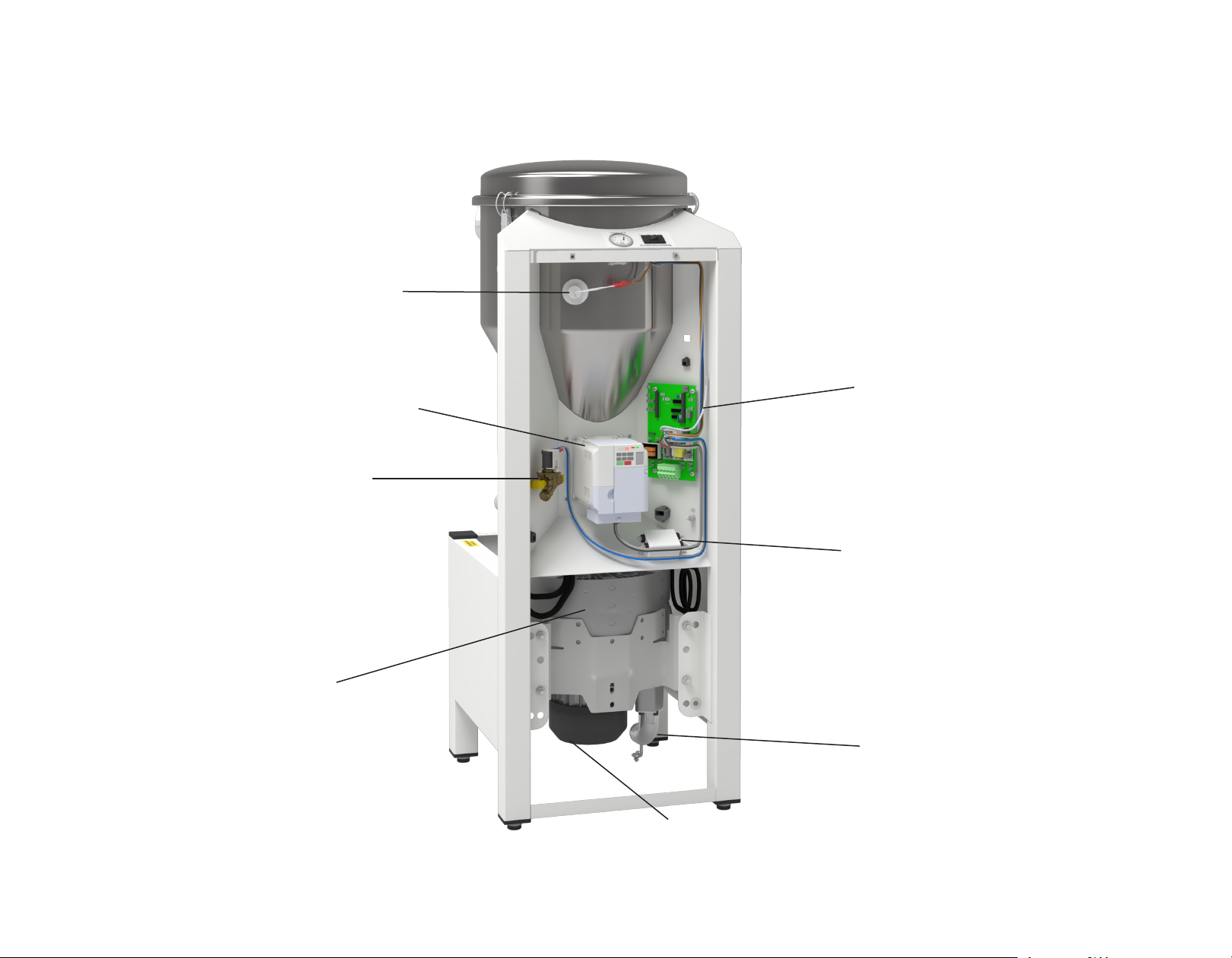
Front Components
Float
Switch
Circuit
VFD
Water
Washdown
Solenoid
Board
86.0897.00 Rev A
Voltage
Line Filter
Impeller
Housing
Exhaust
Elbow
Vacuum
Motor
16
Page 17

A-dec DV Dry Vacuum Service Guide Wiring Diagram
Wiring Diagram
VFD
Display
Comm
Wire
19" Gray
18GA
21" Black
18GA
COMM/Control Board
19" Brown 16GA
ON 19" Blue 18GA
19" Gray 18GA
Remote 19" Black 18GA
Float Switch
(normally open)
Rocker
Switch
24VDC
Solenoid
Valve
Remote Panel
24 VDC Wiring by Others
Light
Run
+24~
LED
Remote
Off
On
80A
MAX
On
Off
Motor
86.0897.00 Rev A
To VFD
14" Red 12GA
14" White 12GA
36"L
Incoming Power
EMC
Filter
78"L
ATTENTION Circuit boards are sensitive to
static electricity. Electrostatic Discharge (ESD)
precautions are required when touching a circuit
board or making connections to or from the circuit
board. Circuit boards should be installed only by
an electrician or qualified service person.
17
Page 18

A-dec DV Dry Vacuum Service Guide Wiring Diagram
Fuse Identification
Fuse IDPurpose Part
Description Fuse ID
Number
F1 Low volt switch
F2
F3 VFD (Variable Frequency
F4
F5 Washdown solenoid and
F6 Low volt switch E0141 FUSE GLASS
F7 CPU board (5V)
transformer (24 Vac) and
CPU board
Drive)
CPU board power feed
(2V)
E0140 FUSE GLASS 2A
250 VAC 5 x 20 mm
E0139 FUSE CERAMIC
20A 250 VAC 5 x
20 mm
E0140 FUSE GLASS 2A
250 VAC 5 x 20 mm
500mA 250VAC
5X20 mm
NOTE To verify the fuse is good, the fuse must be removed from
the board to test for continuity.
COMM/Control Board
F2AL250V
T20AH250V
F7
F2AL250V
F500mAL250V
F5
F6
86.0897.00 Rev A
F1
F2
F3
F4
18
Page 19

A-dec DV Dry Vacuum Service Guide Maintain/Troubleshoot
Maintain/Troubleshoot
Regular Maintenance Tasks
WARNING Before performing any maintenance function, turn
off the vacuum unit and disconnect main power to the vacuum.
Failure to do so may result in injury or equipment damage.
Do not open the service panel or service the vacuum for issues
other than those described in this section, or you may risk injury or
equipment damage. All other service requires a qualified service
technician from your authorized A-dec dealer.
Separator
Tank
Washdown
Waterline
CAUTION Do not clean the vacuum lines with oxidizing or acidic
cleaners with a pH less than 6 or greater than 8 (including bleach,
chlorine, iodine and peroxide). These may lead to the dissolution
of solid mercury which can corrode and damage components in
your system. Use a non‑foaming vacuum‑line cleaner and always
follow the manufacturer’s instructions. For recommendations on
vacuum-line cleaners, contact your authorized A-dec dealer.
To keep your vacuum system running smoothly, be sure to schedule a service
checkup with your authorized A-dec dealer every year. And although the DV
dry vacuum requires very little maintenance, see the table below for important
recommended maintenance tasks.
Frequency Item Task/Procedure
Once or
Twice Daily
Vacuum-line
cleaning.
Separator tank
drain and rinse.
Follow your normal vacuum-line cleaning
protocols to help prevent debris from settling in
the vacuum plumbing.
Turn off the vacuum at the end of the day (from
the master power switch or remote on/off
controls) to initiate the separator tank drain and
rinse cycles. For busier days and larger clinics,
turn off the vacuum once at lunchtime and once
at the end of the day. This will also help you
avoid an unplanned shutoff/drain cycle during a
procedure.
86.0897.00 Rev A
19
Page 20
A-dec DV Dry Vacuum Service Guide Maintain/Troubleshoot
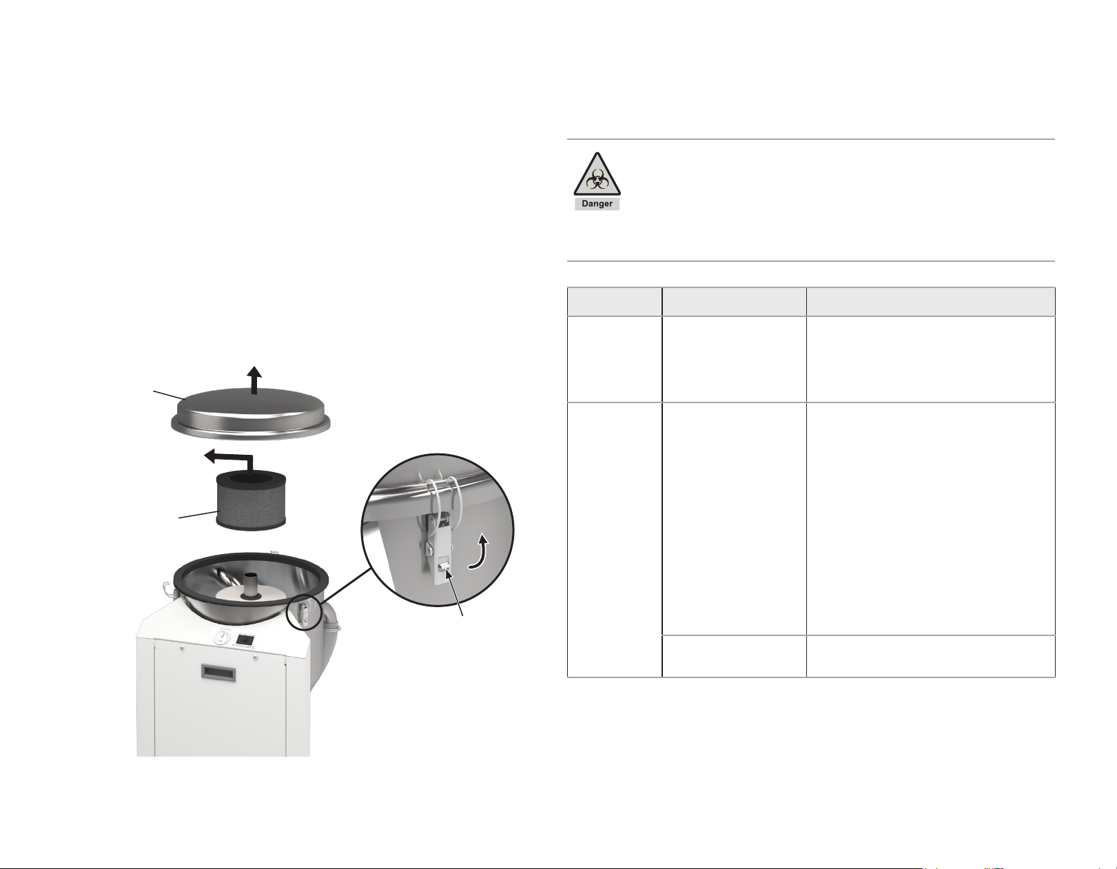
Regular Maintenance Tasks (continued)
WARNING Infectious biohazardous waste may be present. To
prevent cross contamination, follow all infection control and
personal protective equipment (PPE) protocols.
In addition to biohazardous waste, the separator tank filter may
contain amalgam particles. Follow your local regulations when you
dispose of the old filter.
Frequency Maintenance Items Task/Procedure
Tank Lid
Tank Filter
3
2
Safety Clamp
Latch
1111
Press here
and lift.
Weekly/
Monthly
Yearly Tank lter Replace the separator tank lter* once a year.
Exterior case and
tubing connections.
Vacuum Drain Check
Valve.
Use a dry, lint-free cloth to dust off and
clean the exterior. Turn on the system,
listen, and inspect the tubing. If you
discover any leaks or debris, contact your
authorized A-dec dealer for assistance.
Turn off power to the vacuum and wait a few
minutes before following these steps (to
ensure the drain and rinse cycle have
nished):
1. Release the three clamps securing the
separator tank lid to the tank.
2. Remove the lid and ensure that the
tank is empty.
3. Remove the tank filter and replace with
a new one.
*For the separator tank lter replacement kit,
order p/n A0049.
Change the drain check valve.
See page 21
86.0897.00 Rev A
20
Page 21

A-dec DV Dry Vacuum Service Guide Maintain/Troubleshoot
Annual Check Valve Change
CAUTION Never remove the check valve without first inspecting
the inside of the tank to ensure that there are no residual liquids
still trapped inside of the tank.
1. Turn off the vacuum and make sure power has been disconnected.
2. Ensure the tank has been drained of uids.
3. Remove the check valve.
4. Install the new check valve and ensure that the valve ow direction and
mounted positions are correct.
NOTE Ensure the check valves are installed correctly according to
the markings on the manifold that indicate which side should be up,
and an arrow indicating the airflow goes from the manifold to the
vacuum
Flow Points
Towards Drain
86.0897.00 Rev A
21
Page 22
A-dec DV Dry Vacuum Service Guide Maintain/Troubleshoot
Troubleshooting Tasks
The following table is intended to help you identify common issues with your vacuum that may or may not require attention.
Condition Potential Cause Procedure/Remedy
Vacuum motor runs
continuously with little
to no suction.
Vacuum motor won’t run
while the master power
switch is on.
LED push-button or
Smart Shield controls
do not function.
Leak in the vacuum system.
Pinched or kinked vacuum tubing. Check to see if the dental equipment tubing is pinched or kinked. If the tubing is damaged, contact
Stuck separator tank drain check valve (open). Turn off the vacuum to initiate a drain and rinse cycle. If this does not remedy the condition, contact
Stuck separator tank oat switch. Turn off the vacuum to initiate a drain and rinse cycle. If this does not remedy the condition, contact
Vacuum is in power safe mode.
(Note: power safe mode occurs when the vacuum
loses power and cannot restart within 15 seconds.)
Master power switch on the vacuum is not in
the REMOTE position.
Close all vacuum instruments and listen for leaks throughout the system. Check
the vacuum runs continuously and cannot reach or consistently maintain 10 inHg (34 kPa) (or your
adjusted preset level), contact A-dec Customer Service.
Note: Check this when all instruments are closed and the system is at a rest.
A-dec Customer Service.
A-dec Customer Service.
A-dec Customer Service.
To resume normal operation:
1. Turn off the vacuum master power switch.
2. Disconnect the power to the vacuum for 3 minutes.
3. Reconnect the power.
4. Turn on the vacuum master power switch or put it in the REMOTE position. Resume
normal use.
If this does not remedy the condition, contact A-dec Customer Service.
Ensure that the master power switch on the vacuum is in the REMOTE position. If it is, and you have
push-button controls, contact A-dec Customer Service. If the master power switch is in the REMOTE
position and you have the Smart Shield touchscreen, see the remedy below.
the vacuum gauge. If
86.0897.00 Rev A
Communication disruption/fault between system and
Smart Shield touchscreen.
Tap on at the top of the touchscreen, then tap RESET. If this does not resolve the condition,
unplug the Smart Hub router power cord, wait 10 seconds, then plug it back in (note: this will reset
the annual maintenance reminder to 12 months). If this does not resolve the condition, contact
A-dec Customer Service.
22
Page 23

A-dec DV Dry Vacuum Service Guide Maintain/Troubleshoot
Status Lights
Status Lights on the
Internal Circuit Board
Mean This...
The vacuum has been turned on at the local switch, and is running.
The Remote switch to the vacuum, either the Smart Shield touchscreen or the LED Push-Buttons, has been enabled
from the local switch.
The On signal is not detected from the Remote switch, so the vacuum is not running.
The Remote switch to the vacuum, either the Smart Shield touchscreen or the LED Push-Buttons, has been enabled
from the local switch.
The On signal is detected from the Remote switch, so the vacuum is running.
86.0897.00 Rev A
The Float switch is on, which stops the vacuum because water has lled up the vacuum’s tank.
The vacuum starts 10 seconds after the water level has dropped enough to turn the Float switch off, then this light
turns off.
23
Page 24

A-dec DV Dry Vacuum Service Guide Maintain/Troubleshoot
Circuit Board Electrical Test Locations
86.0897.00 Rev A
ATTENTION Circuit boards are sensitive to static electricity.
Electrostatic Discharge (ESD) precautions are required when
touching a circuit board or making connections to or from the
circuit board. Circuit boards should be installed only by an
electrician or qualified service person.
24
Page 25

A-dec DV Dry Vacuum Service Guide Maintain/Troubleshoot
Initial Startup Checklist
WARNING This system can start automatically without warning.
• Inspect unit for any visible signs of damage that may have occurred in shipment or during installation.
• Verify the electrical connection attachments, and that incoming line voltage is between 200 and 240 VAC.
• Activate main disconnect switch or circuit breaker.
• Turn on the vacuum, and ensure unit starts. If it does not start, refer to “Status Lights” on page 23.
• Check the gauge on the front of the vacuum for proper vacuum level. See the Set "HG column in the table “Site Specifications and Sizing Information” on
page 4.
• Check that all of the HVEs and SEs have proper suction.
• Check for leaks in all connections and the piping system.
Turn off the vacuum.
• Optional - Verify washdown operation begins 45-60 seconds after turning off the vacuum. Listen for the solenoid to open the water line and look at the drain
check valve to confirm that the water is draining.
• Verify the Drain hose flows cleanly and has no low spots to trap debris.
• If remote buttons or a touchscreen are in use:
• Switch the rocker to the remote position.
• Verify the system turns on /off with remote switches or trouchscreen.
• If the system uses remote monitoring, call A-dec Customer Service to confirm it is reporting.
86.0897.00 Rev A
25
Page 26

A-dec Headquarters
2601 Crestview Drive
Newberg, Oregon 97132
United States
Tel: 1.800.547.1883 within USA/CAN
Tel: +1.503.538.7478 outside USA/CAN
Fax: 1.503.538.0276
www.a-dec.com
A-dec St. Louis
1601 Manufacturers Drive
Fenton, MO 63026 USA
86.0897.00 Rev A
Date of Issue 2021-02-02
Copyright 2021 A-dec, Inc.
All rights reserved.
 Loading...