

Page 1
Service Guide
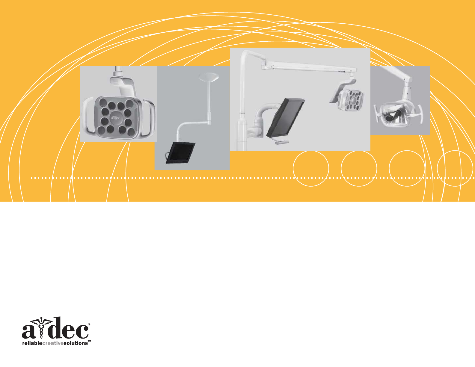
A-dec Dental Lights and Monitor Mounts
Page 2

A-dec Dental Lights and Monitor Mounts b
Copyright
© 2014 A-dec Inc. All rights reserved.
A-dec Inc. makes no warranty of any kind with regard to this material,
including, but not limited to, the implied warranties of merchantability and
fitness for a particular purpose. A-dec Inc. shall not be held liable for any
errors contained herein or any consequential or other damages concerning
the furnishing, performance or use of this material. The information in this
document is subject to change without notice. If you find any problems in
the documentation, please report them to us in writing. A-dec Inc. does not
warrant that this document is error-free.
No part of this document may be copied, reproduced, altered, or transmitted
in any form or by any means, electronic or mechanical, including
photocopying, recording, or by any information storage and retrieval system,
without prior written permission from A-dec Inc.
Trademarks and Additional Intellectual Property Rights
A-dec, the A-dec logo, A-dec 500, A-dec 300, Cascade, Cascade Master
Series, Century Plus, Continental, Decade, ICX, ICV, Performer, Preference,
Preference Collection, Preference ICC, and Radius are trademarks of A-dec
Inc. and are registered in the United States and other countries. A-dec
400, A-dec 200, Preference Slimline, and reliablecreativesolutions are also
trademarks of A-dec Inc. None of the trademarks or trade names in this
document may be reproduced, copied, or manipulated in any manner without
the express, written approval of the trademark owner.
Regulatory Information
Regulatory information mandated by agency requirements is provided
Regulatory Information, Specifications, and Warranty document (
which is available in the Document Library at www.a-dec.com. This document
includes:
• Serial number identification
• Software revisions
• Warranty statement
• Deluxe touchpad help messages
• Intended application and use statements
• Identification of symbols
• Environmental specifications
• Classification of equipment
• Electrical rating and electromagnetic information
• Chair load capacity
p/n
in the
86.0221.00),
Product Service
Product service is available through your local authorized A-dec dealer.
For service information, or to locate an authorized dealer, contact A-dec at
1.800.547.1883 in the USA and Canada or 1.503.538.7478 worldwide, or visit
www.a-dec.com.
Certain touchpad symbols are proprietary to A-dec Inc. Any use of these
symbols, in whole or in part, without the express written consent of A-dec
Inc., is strictly prohibited.
Page 3

A-dec Dental Lights and Monitor Mounts
Service Guide
Page 4

A-dec Dental Lights and Monitor Mounts Contents 2
Contents
Overview .......................................................... 4
Customer Service ...............................................................4
U.S. and Canada .................................................................... 4
United Kingdom ..................................................................... 4
Australia .............................................................................. 4
Web Contact ......................................................................... 4
Other Sources of Information .................................................4
Dental Lights and Monitor Mounts Service Reference ....................... 4
Other A-dec Service Documents ................................................ 4
A-dec Dental Lights .............................................. 5
Dental Light Specications ....................................................6
Dental Light Mounting Locations .............................................7
Dental Light Circuit Breaker Locations ......................................8
Dental Light Operations ........................................................9
Dental Light Touchpad Controls .................................................. 9
Power and Intensity Settings ..................................................... 10
A-dec LED Dental Light Manual On/Off and Intensity ..................... 10
A-dec 571/572 and 6300 Dental Light (Halogen 3-Axis)
Manual On/Off and Intensity .................................................. 10
A-dec 371/372 Dental Light (Halogen 2-Axis) Manual On/Off
and Intensity ..................................................................... 10
Halogen Dental Light Intensity Switch Voltage Measurements ........... 11
Auto On/Off Function ........................................................... 11
Dental Light Bulb Replacement .................................................. 12
A-dec 571/572 and 6300 Dental Light (Halogen 3-Axis) ................... 12
A-dec 371/372 Dental Light (Halogen 2-Axis) ............................... 13
Dental Light Shield Cleaning ..................................................... 14
Halogen Dental Light Shield ................................................... 14
LED Dental Light Shield ........................................................ 14
Dental Light Adjustments .................................................... 15
A-dec LED Dental Light Rotation Adjustments................................. 15
LED Light Range of Motion Adjustments ..................................... 15
LED Light Forward Tilt Adjustment ........................................... 15
LED Light Horizontal and Diagonal Rotation Adjustment .................. 15
A-dec 571/572 and 6300 Dental Light (Halogen 3-Axis) Rotation
Adjustments ........................................................................ 16
571/572/6300 Light Head Rotation ........................................... 16
571/572/6300 Horizontal Rotation ........................................... 16
571/572/6300 Diagonal Axis Rotation ........................................ 17
571/572/6300 Vertical Rotation ............................................... 17
571/572/6300 Focus ............................................................ 17
A-dec 371/372 Dental Light (Halogen 2-Axis) Rotation Adjustments ...... 18
371/372 Horizontal Rotation .................................................. 18
371/372 Vertical Rotation ...................................................... 18
Dental Light Flexarm Counterbalance Adjustment ........................... 18
Dental Light Wiring and Power Connections .............................. 19
A-dec LED Dental Light Circuit Board Components ........................... 20
LED Driver Circuit Board Identication ...................................... 20
LED Dental Light Circuit Board Indicators ................................... 20
LED Array Board Indictors ...................................................... 21
LED Dental Light Indicator Light Circuit Board Identication ............ 22
LED Indicator Light Board Indictors ........................................... 22
LED Dental Light Terminal to CAN Adapter Board Identication ......... 23
CAN Adaptor Board ............................................................. 23
A-dec LED Dental Light (570L — 577L) Wiring ................................. 24
571L on an A-dec 511 Chair .................................................... 24
571L on an A-dec 411 Chair .................................................... 25
571L on an A-dec 311 Chair .................................................... 26
572L on an A-dec 511 Chair, Radius Arm Mounted .......................... 27
574L Cabinet Mounted .......................................................... 28
575L Wall Mounted .............................................................. 29
576L Ceiling Mounted ........................................................... 30
577L Track Mounted ............................................................. 31
A-dec 571/572 and 6300 Dental Light (Halogen 3-Axis) Circuit
Board Components ................................................................. 32
571/572/6300 Dental Light Output Functions .............................. 32
511 Chair Circuit Board Indicators ........................................... 33
511 Chair Circuit Board Identication ........................................ 33
A-dec 6300 Dental Light Relay Circuit Board .................................. 34
6300 Dental Light Output Functions .......................................... 34
6300 Dental Light Relay Circuit Board LED Indicators ..................... 35
Page 5

6300 Dental Light Relay Circuit Board Identication ...................... 35
A-dec 571/572 and 6300 Dental Light (Halogen 3-Axis) Wiring ............. 36
6300 Ceiling, Wall, and Preference Mount Switch and Data
Line Connections ................................................................ 36
6300 Track Light Switch Connections and Data Line
(2004 and Later) ................................................................. 37
6300 Track Light Switch Connections and Data Line
(2003 and Earlier) ............................................................... 38
A-dec 571/572 and 6300 Dental Light (Halogen 3-Axis) Transformer ..... 40
100 VAC Transformer Wiring ................................................... 40
110-120 VAC Transformer Wiring .............................................. 40
220-240 VAC Transformer Wiring .............................................. 41
A-dec 371/372 Dental Light (Halogen 2-Axis) Circuit
Board Components ................................................................ 42
A-dec 311/411 Dental Chair Circuit Board for 371/372 Dental
Light on an A-dec 311 and 411 Chair ......................................... 42
311/411 Chair Circuit Board LED Indicators ................................. 43
311/411 Chair Circuit Board Identication .................................. 43
A-dec 511 Chair Board Components for 371/372 Dental Light
on an A-dec 511 Chair .......................................................... 44
371/372 Dental Light Output Functions...................................... 44
511 Chair Circuit Board LED Indicators....................................... 45
511 Chair Circuit Board Identication ........................................ 45
A-dec 371/372 Dental Light Relay Circuit Board ........................... 46
371/372 Dental Output Functions ............................................ 46
371/372 Dental Light Relay Board LED Indicators .......................... 47
371/372 Dental Light Relay Circuit Board Identication .................. 47
371/372 and 571L/572L Wiring on the 311 and 411 Chair Board ........... 48
A-dec 371/372 Dental Light (Halogen 2-Axis) Wiring ......................... 49
371/372 Dental Light Connections ............................................ 49
On/Off Switch .................................................................... 49
A-dec 371/372 Dental Light Wire Connections on an
A-dec 311 Chair .................................................................. 50
A-dec 371/372 Dental Light Wire Connections on an
A-dec 511 Chair .................................................................. 51
A-dec 371/372 Dental LIght Wire Connections on Cascade, Decade,
Performer, Priority Chairs ...................................................... 52
Dental Light Troubleshooting ................................................ 54
A-dec Monitor Mounts .......................................... 57
Monitor Mount Specications and Adjustments .......................... 58
Monitor Mount Specications .................................................... 58
Monitor Mount Adjustments ...................................................... 58
Tray Holder Tension Adjustment (581) .......................................... 60
Panning Friction Adjustment (587) .............................................. 60
86.0326.00 Rev C Contents 3
Page 6

A-dec Dental Lights and Monitor Mounts Overview 4
Overview
Customer Service
For questions not addressed in this document, contact A-dec Customer Service
using contact information for your region.
U.S. and Canada
A-dec Inc.
2601 Crestview Drive
Newberg, OR 97132 USA
Tel: 1.800.547.1883 within US and Canada
Tel: 1.503.538.7478 outside US and Canada
www.a-dec.com
www.a-dec.biz
United Kingdom
A-dec United Kingdom
Austin House, 11 Liberty Way
Nuneaton, Warwickshire CV11 6RZ
England
Tel: 0800 ADECUK (233285) within UK
Tel: 44 24 7635 0901 outside UK
www.a-dec.co.uk
Other Sources of Information
Dental Lights and Monitor Mounts Service Reference
This document is a companion to the A-dec Dental Lights and Monitor Mounts
Service Reference (p/n 86.0328.00). The Service Reference contains flow
diagrams and illustrated parts breakdown for lights and monitor mounts.
Circuit board component information is available in both this document and
the Service Reference.
Other A-dec Service Documents
The A-dec 311, 411, and 511 Dental Chairs Service Guide (p/n 86.0380.00)
contains service, maintenance, and troubleshooting content. The A-dec 311,
411, and 511 Dental Chairs Service Reference (p/n 86.0381.00) contains illustrated
parts breakdown content. Circuit board components and flow diagrams are in
both documents. These documents include cuspidors, floor boxes, and support
centers.
The A-dec 300, 400, and 500 Delivery Systems Service Guide (p/n 86.0382.00)
contains service, maintenance, and troubleshooting content. The A-dec 300, 400,
and 500 Delivery Systems Service Reference (p/n 86.0383.00) contains illustrated
parts breakdown content. Circuit board components and flow diagrams are in
both documents. These documents include cuspidors, floor boxes, and support
centers.
Australia
A-dec Australia
Unit 8, 5-9 Ricketty St.
Mascot, NSW 2020
Australia
Tel: (02) 8332 4000
1.800.225.010
www.a-dec.com.au
Web Contact
Partner Resources websites: www.a-dec.biz.
Page 7
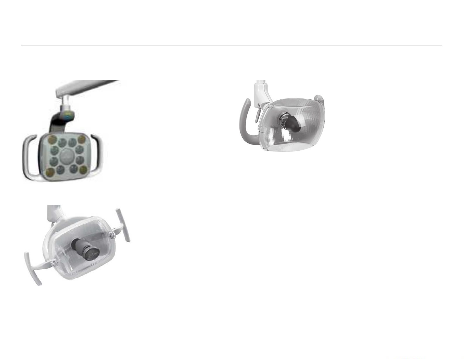
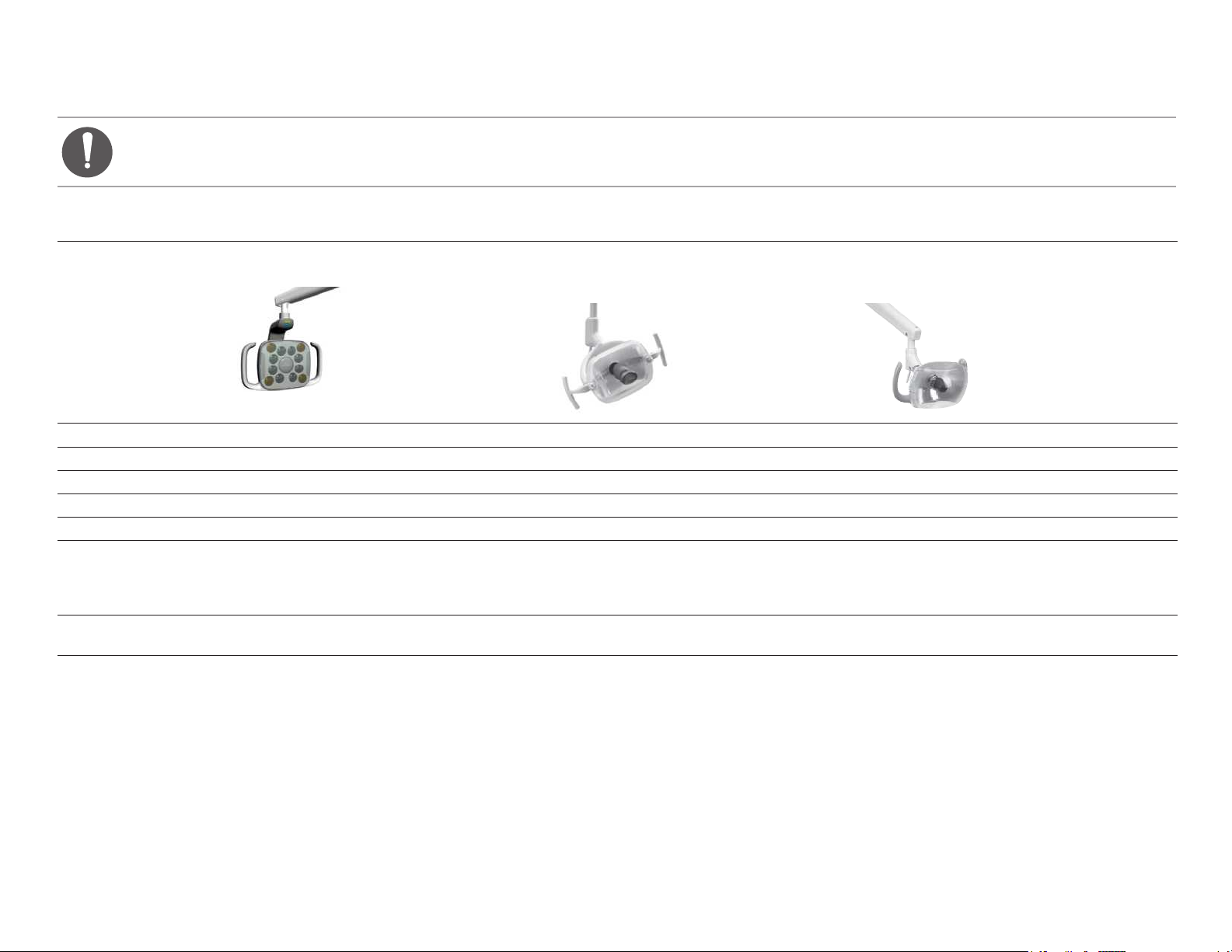
A-dec Dental Lights
This section provides service, usage, adjustments, and maintenance content for A-dec dental lights.
A-dec LED Dental Light (570L — 577L)
A-dec 571/572 and 6300 Dental Light (Halogen 3-Axis)
A-dec 371/372 Dental Light (Halogen 2-Axis)
86.0326.00 Rev C A-dec Dental Lights 5
Page 8
A-dec Dental Lights and Monitor Mounts A-dec Dental Lights 6
Dental Light Specifications
NOTE Specications are subject to change without notice. Some requirements may vary from country to country. For more information, contact your
authorized A-dec dealer.
A-dec LED Dental Light (570L - 577L) A-dec 571/572 and 6300 Dental Light
(Halogen 3-Axis)
Focal Range 16” - 30” (400 mm - 750 mm) 18” - 31” (457 - 787 mm) 18” - 31” (457 - 787 mm)
Bulb n/a Quartz Xenon Halogen, single-end prongs Quartz Xenon Halogen, single-end prongs
Bulb Rating LED: White HBLED, 88-92 CRI 17 V / 95 W 17 V / 95 W
Color temperature White 5,000 Kelvin 5,000 Kelvin 5,000 Kelvin
Light pattern 5.7” x 3.8” at 27.6” (145 mm x 95 mm at 700 mm) 3.3” x 6.3” at 27.6” (84 mm x 160 mm at 701 mm) 3.3” x 6.3” at 27.6” (84 mm x 160 mm at 701 mm)
Nominal Light Intensity ** Cure-safe Mode: 25,000 lux (2323 fc)
High: 30,000 lux (2787 fc)
Medium: 25,000 lux (2323 fc)
Low: 15,000 lux (1394 fc)
Heat Output
(BTU per Hour)
* For electrical specifications, identification of symbols, and other regulatory requirements, refer to the Regulatory Information, Specifications, and Warranty Instructions for Use
(p/n 86.0221.00).
** The LED cure-safe mode provides effective illumination while preventing the premature curing of photo-initiated composites, sealants, and adhesives. This mode uses a medium intensity
light setting and a non-reactive wavelength of light.
24 325 325
High: 24,000 lux (2230 fc)
Medium: 20,000 lux (1858 fc)
Low: 8,000 lux (743 fc)
A-dec 371/372 Dental Light
(Halogen 2-Axis)
High: 24,000 lux (2230 fc)
Medium: 20,000 lux (1858 fc)
Composite: 8,000 lux (743 fc)
Page 9
Dental Light Mounting Locations
Cabinet-Mounted
(LED and 6300)
Radius Style (LED, 371/372, 571/572, 6300)
Dental Light on A-dec 500 Chair Support Mount
Ceiling-Mounted
(LED and 6300)
Track-Mounted
(LED and 6300)
LED, 371/372, 571/572 Dental Light on
A-dec 300 Chair and 2” Post Mount Support Mount
Wall-Mounted
(LED and 6300)
LED, 371/372, 571/572 Dental Light on
A-dec 500 Chair Support Side Mount
86.0326.00 Rev C A-dec Dental Lights 7
Page 10
A-dec Dental Lights and Monitor Mounts A-dec Dental Lights 8
CB 1
MAINS
INPUT
VACUUM
RELAY
13A @ 250V~ MAX
POWER ON MODE
ASSISTANT'S ARM
& CONTROL HEAD
CB 3
8A MAX
OUTPUT
0V~ 24V~
DATA
CB 5
CB 4
MAINS OUTPUT
POWER 4A MAX
SIDE
SUPPORT
ARM
DENTAL
LIGHT
MASTER TOGGLE
CONTROL OF POWER
SWITCH ON
NC COM NO
NO CONNECTION
REQUIRED
SWITCH OFF
CB 2
CONNECT AIR SUPPLY
FROM MASTER TOGGLE
10
A
M
P
10
A
M
P
10
A
M
P
10
A
M
P
10
A
M
P
10
A
M
P
10
A
M
P
Dental Light Circuit Breaker Locations
A circuit breaker will interrupt the flow of electricity under abnormal conditions. If the circuit breaker should trip, inspect the wiring to ensure there are no
shorts, and reset by pushing the circuit breaker. If the circuit breaker for the dental light is located on the power supply, its location varies by chair. For non-chair
based lights, the operatory circuit breaker is used.
Chair Model/
Location
Circuit Breaker Location
Mounting Location Circuit Breaker Location
Track Mount
A-dec 311/411
Under Motor
Pump Cover
Cabinet Mount
®
A-dec 511
Under Motor
Post Mount: Cascade,
Decade,
®
Performer,®
early model A-dec chairs
Pump Cover
Ceiling Mount
Cascade,
Performer,
®
Decade,®
®
A-dec
Before
June 2012
Effective June
2012
200, early model
A-dec chairs
Under the Utility Floor
Box Cover
Wall Mount
Page 11
Dental Light Operations
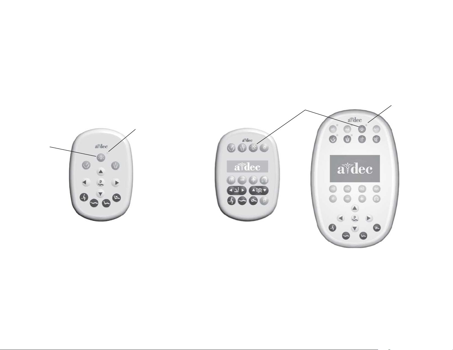
Dental Light Touchpad Controls
Dental light can be operated from the touchpad on the A-dec 200, 300 and 500 systems. Press the light button on the touchpad to turn on the light, and press and
hold the light button to turn the light off.
Dental Light
Button
Standard Touchpad
Dental Light
Indicator
Deluxe Touchpads
Dental Light Button
Dental Light
Indicator
86.0326.00 Rev C A-dec Dental Lights 9
Page 12
A-dec Dental Lights and Monitor Mounts A-dec Dental Lights 10
B
B
Power and Intensity Settings
A-dec LED Dental Light Manual On/Off and Intensity
The mode button is used to select the intensity level. The illuminated indicator
shows the selected mode. The dental light retains the selected mode unless the
entire system is turned off, which resets the light to medium intensity.
Mode Indicator
Panel
Power Button
Mode Button
Cure-Safe
High
Medium
Low
A-dec 571/572 and 6300 Dental Light (Halogen 3-Axis) Manual On/Off and Intensity
The on/off switch is used to activate the light. The intensity switch toggles
between this light’s three intensity settings (composite, high, and medium).
The dental light button on the touchpad works as a three-way switch with the
on/off switch on the light.
A-dec 371/372 Dental Light (Halogen 2-Axis) Manual On/Off and Intensity
The on/off switch is used to activate the light and to toggle between
intensities. With a touchpad, press the dental light button to activate the light
and to toggle between intensity settings.
(Older models do not
have on/off switch)
NOTE For the A-dec 371/372 Dental Light, medium and composite
intensity settings are available if preferred over high and
composite. Contact A-dec Customer Service for instructions.
Intensity
Switch
On/Off Switch
Page 13
Halogen Dental Light Intensity Switch Voltage Measurements
The following are the voltage measurements for Halogen lights. If the switch
needs to be replaced, the replacement kit is p/n 90.1039.00.
Position Voltage Wire
Open 5 VDC White
Closed 0 VDC White
NOTE All DC voltage measurements are taken with the black
multimeter lead on the black/white wire.
CAUTION Circuit boards are sensitive to static electricity.
Electrostatic Discharge (ESD) precautions are required when
touching a circuit board or making connections to or from the
circuit board. Circuit boards should be installed only by an
electrician or qualied service person.
Auto On/Off Function
All of the dental lights turn on when the chair back reaches a preset operating
position. When the chair back moves out of the operating position, the light
automatically turns off.
• To turn off the auto on/off feature, press and hold the program and dental
light buttons for three seconds at the same time. One beep confirms the
feature is off.
• To turn on the auto on/off feature, press and hold the program and dental
light buttons for three seconds at the same time. Three beeps confirm the
feature is on.
86.0326.00 Rev C A-dec Dental Lights 11
Page 14
A-dec Dental Lights and Monitor Mounts A-dec Dental Lights 12
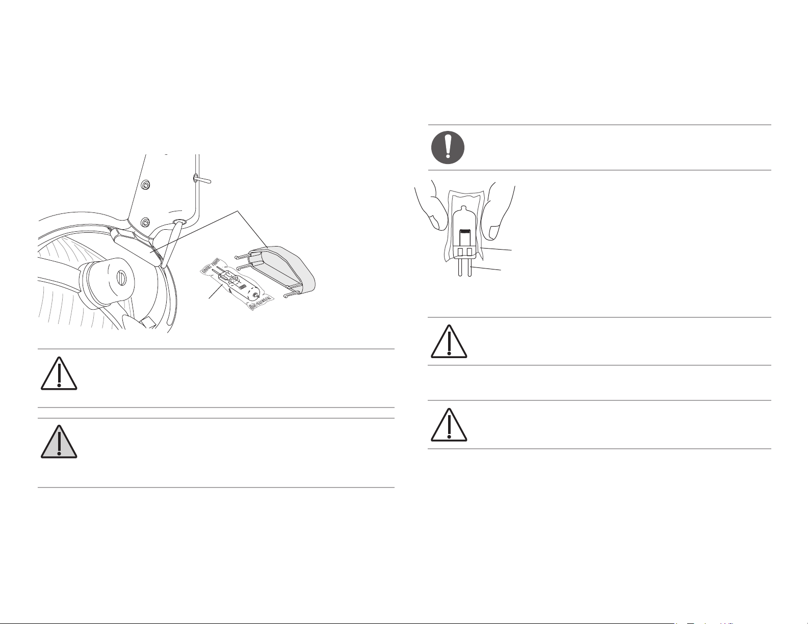
Dental Light Bulb Replacement
A-dec 571/572 and 6300 Dental Light (Halogen 3-Axis)
1. Turn off the light, and allow the light to cool.
2. Pull the plastic holder from the light yoke. Remove the bulb from the holder,
but do not remove the outer wrapper.
Holder
Bulb
CAUTION Do not remove the outer wrapper when handling the
new bulb. Finger oils can affect light performance and severely limit
bulb life. If you should inadvertently touch the bulb, gently clean it
with cotton dampened with isopropyl or ethyl alcohol.
WARNING To avoid burning your ngers, allow the light shield to
cool before removing. Never operate the dental light with the light
shield removed. The light shield contains UV blocking additives.
The light shield is also your protection in the unlikely event that
the bulb shatters.
5. Hold the new bulb in its outer wrapper with the pins facing away, and
carefully insert it in the socket. The bulb base is fragile and can break under
excess pressure.
NOTE Part of the pins are still visible when the bulb is fully
inserted.
Outer Wrapper
New Bulb
6. Remove and discard the outer wrapper, reinstall the light shield, and secure
with the toggles.
CAUTION Do not attempt to install the light shield if it has
a broken tab. Contact your authorized A-dec dealer for a
replacement shield and install before operating the light.
7. Verify the operation of the light by turning it on and operating it at each
intensity setting.
CAUTION Use of a halogen bulb other than A-dec p/n
041.709.00 (Philips 14623, G 6.35, 17V, 95W) may result in
damage to the bulb socket.
8. Reorder the bulb, p/n 041.709.00.
3. Release the toggles on the light shield and set the shield aside.
4. Use a gauze pad or cloth to protect ngers. Carefully pull the old bulb from
its socket and discard.
Page 15
A-dec 371/372 Dental Light (Halogen 2-Axis)
B
Tab
B
A spare bulb is included with your dental light. Follow these steps when
replacing the bulb.
WARNING To avoid burning your ngers, allow the light shield to
cool before removing. Never operate the dental light with the light
shield removed. The light shield contains UV blocking additives.
The light shield is also your protection in the unlikely event that
the bulb shatters.
1. Turn off the light and allow it to cool.
2. Gently pull out on the light shield tabs, then pull the edges of the shield
toward you. Set the light shield aside.
Shield
Bulb Cap
Tab
4. Using a gauze pad or cloth to protect your ngers, carefully pull the old bulb
from its socket. Discard the bulb.
CAUTION Do not remove the outer wrapper when handling the
new bulb. Finger oils can affect light performance and severely
limit bulb life. If you should inadvertently touch the bulb, gently
clean it with cotton dampened with isopropyl or ethyl alcohol.
5. Holding the new bulb in its outer wrapper with the pins away from you,
carefully insert the bulb pins into the socket. A small section of each pin is
still visible when the bulb is fully seated.
Outer
Wrapper
New Bulb
6. Remove and discard the outer wrapper, then reinstall the bulb cap and light
shield.
CAUTION Do not attempt to install the light shield if it has
3. Remove the bulb cap by rotating it counterclockwise. Set the bulb cap aside.
a broken tab. Contact your authorized A-dec dealer for
replacement shield and install before operating the light.
CAUTION Take care when handling the bulb. The bulb base is
fragile and can break under excessive pressure.
7. Verify the operation of the light by turning it on and operating it at each
intensity setting.
8. Reorder the bulb, p/n 041.709.00.
86.0326.00 Rev C A-dec Dental Lights 13
Page 16
A-dec Dental Lights and Monitor Mounts A-dec Dental Lights 14
Dental Light Shield Cleaning
Halogen Dental Light Shield
1. Turn off the dental light.
WARNING To avoid personal injury, be sure that the light has
cooled before cleaning it.
3. Release the toggles on either side of the light to remove the light shield.
4. To clean the light shield use a small amount of non-abrasive liquid soap and
warm water to wash it. Rinse and dry with a non-abrasive, lint free cloth.
If necessary, soak the pad or cloth with water or with a diluted solution of
mild dish washing liquid before cleaning. Make certain no residue remains on
the surface. Do not use abrasives or chlorine (such as household bleach) on the
surface of the reflector. These can damage or discolor the reflector surface.
CAUTION Do not rub heavily, clean the light shield when it is hot,
or soak the shield assembly in cleaning solution. Doing so may
damage the shield assembly components. Clean the light shield
only as instructed.
CAUTION Do not attempt to install the light shield if it has
a broken tab. Contact your authorized A-dec dealer for a
replacement shield and install before operating the light.
LED Dental Light Shield
A-dec recommends barriers to protect the dental light shield. In the event that
the light shield needs to be cleaned, carefully clean the light shield in place
using a soft cotton cloth with non-abrasive soap and water.
Do not remove the shield unless absolutely necessary. The shield is fitted with
a gasket to keep dust and debris from entering the lens assembly. If liquid or
dirt should bypass the gasket, the shield may be removed for cleaning.
CAUTION Only remove the shield if absolutely necessary. Use
a at-blade tool that won’t damage the light housing. After
removing the shield, do not touch or attempt to clean the multilens assembly or you may damage the components.
Reflector
Toggle
Light Shield
Page 17
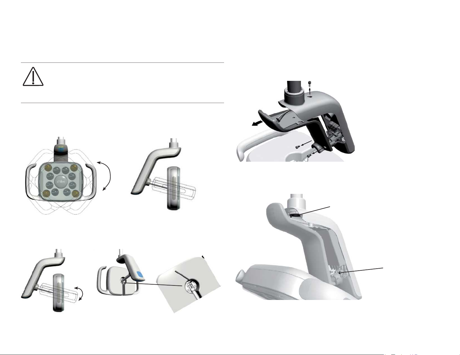
Dental Light Adjustments
A-dec LED Dental Light Rotation Adjustments
CAUTION Circuit boards are sensitive to static electricity.
Electrostatic Discharge (ESD) precautions are required when
touching a circuit board or making connections to or from the
circuit board. Circuit boards should be installed only by an
electrician or qualied service person.
LED Light Range of Motion Adjustments
The LED light offers three axes of rotation.
LED Light Horizontal and Diagonal Rotation Adjustment
To adjust the horizontal and diagonal tension, remove the indicator cover.
1. Use a 7/64” hex key to remove the three screws in the indicator cover.
2. To adjust the friction, turn the locking nut clockwise to increase the tension.
3. To adjust the diagonal tension, turn the screw clockwise to increase the
tension.
Clockwise increases the tension.
LED Light Forward Tilt Adjustment
To adjust the forward tilt motion of the light head, use a 7/64”
hex key to turn the tension screw clockwise to increase tension or
counterclockwise to decrease tension.
Clockwise increases
the tension.
4. Use the three screws to install the indicator cover.
86.0326.00 Rev C A-dec Dental Lights 15
Page 18
A-dec Dental Lights and Monitor Mounts A-dec Dental Lights 16
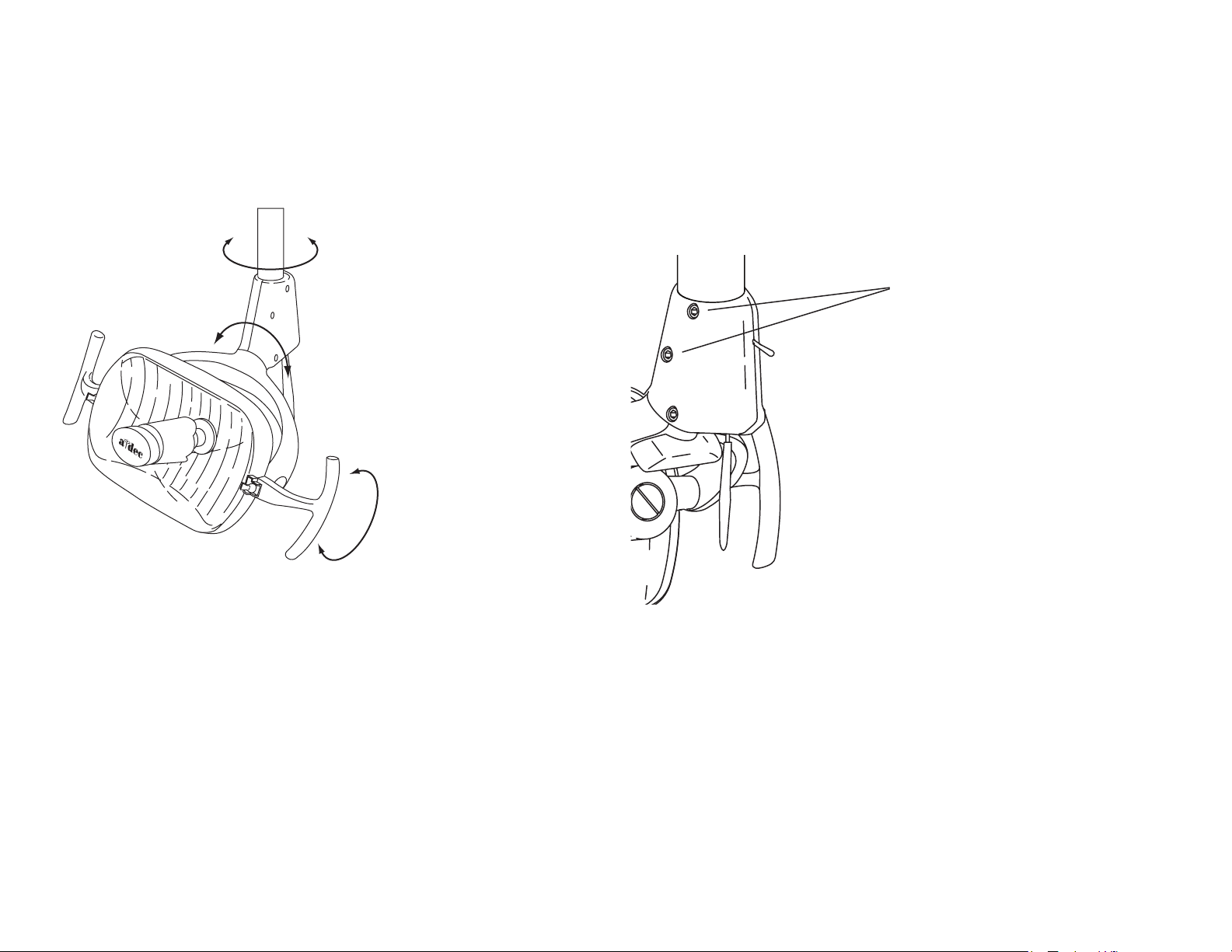
A-dec 571/572 and 6300 Dental Light (Halogen 3-Axis) Rotation Adjustments
571/572/6300 Light Head Rotation
The light head needs adjusting if it is difficult to position, moves too easily, or
drifts out of position.
Horizontal Rotation
Diagonal Rotation
Vertical Rotation
571/572/6300 Horizontal Rotation
Use a hex key to make horizontal rotation adjustments, beginning with the top
screw on both sides of the switch housing.
• Increase the tension by turning the screws clockwise.
• Loosen the tension by turning the screws counterclockwise.
Horizontal Rotation
Tension Screws
Page 19
571/572/6300 Diagonal Axis Rotation
Adjust the screw at the bottom of the switch housing.
• Increase the tension by turning the screw clockwise.
• Loosen the tension by turning the screw counterclockwise
• To eliminate all movement in the diagonal axis, tighten the adjustment
screw until it is tight.
Diagonal Axis
Tension Screw
571/572/6300 Vertical Rotation
1. On one side of the light head, loosen the setscrew.
2. Remove the light yoke plug.
3. Use a large at-blade screwdriver to turn the adjustment screw under the
light yoke plug.
• Increase the tension by turning the screw clockwise.
• Loosen the tension by turning the screw counterclockwise
4. Retighten the setscrew, and reinstall the light yoke plug.
571/572/6300 Focus
1. Place a white towel over the chair headrest to represent the oral cavity.
2. Position the light head at the distance normally used when working in the
oral cavity (select a distance representative of most procedures).
3. Turn the light on.
4. Use a large screwdriver to turn the focus adjusting screw until the light is
most uniform.
Focus Adjustment Screw
Light Yoke Plug
Setscrew
86.0326.00 Rev C A-dec Dental Lights 17
Page 20
A-dec Dental Lights and Monitor Mounts A-dec Dental Lights 18
A-dec 371/372 Dental Light (Halogen 2-Axis) Rotation Adjustments
371/372 Horizontal Rotation
To adjust the horizontal rotation, use a 5/32” hex key to tighten or loosen the
adjustment screw at the top of the light housing.
Horizontal
Tension
371/372 Vertical Rotation
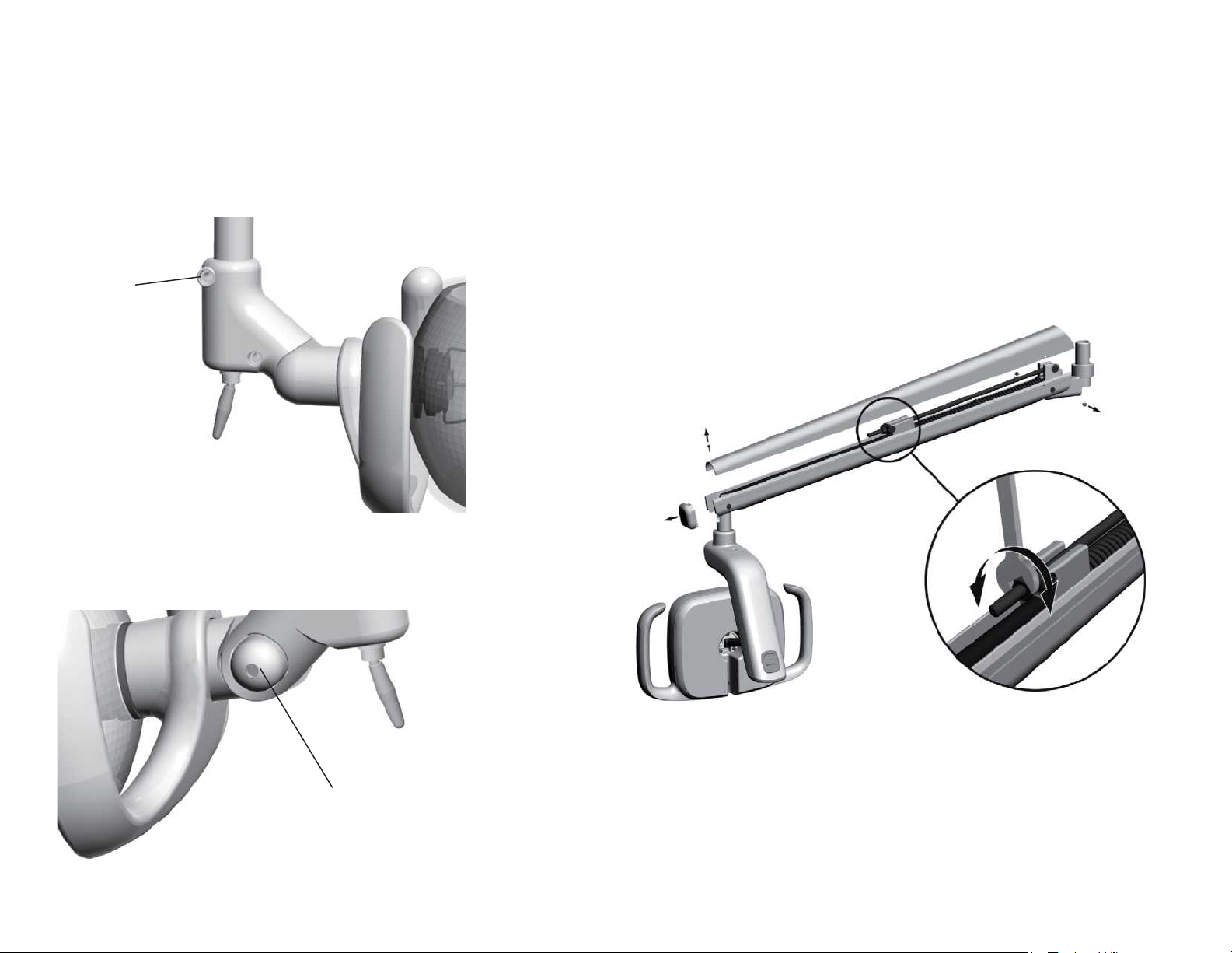
Dental Light Flexarm Counterbalance Adjustment
To adjust the flexarm counterbalance:
1. Use a Phillips head screwdriver to remove the end caps.
2. Use a hex key to remove the two screws that secure the cover.
3. Remove the cover.
4. Use a 1/2” combination wrench to adjust the nut on the end of the spring.
• If the dental light drifts down, turn the nut clockwise.
• If the dental light drifts up, turn the nut counterclockwise.
5. Set the cover back onto the exarm (but do not reattach) and check for drift.
To adjust the vertical rotation, use a 3/16” hex key to tighten or loosen the
vertical tension screw.
Vertical Tension Screw
Page 21

Dental Light Wiring and Power Connections
This section outlines the connections from the power source through switches and boards to the light head interior.
A-dec LED Dental Light
570L - 577L
A-dec 571/572 and 6300 Dental
Light (Halogen 3-Axis)
A-dec 371/372 Dental Light
(Halogen 2-Axis)
• A-dec LED Dental Light Circuit Board Components, page 20
• A-dec LED Dental Light (570L — 577L) Wiring, page 24
• A-dec 571/572 and 6300 Dental Light (Halogen 3-Axis) Circuit Board Components, page 32
• A-dec 571/572 and 6300 Dental Light (Halogen 3-Axis) Wiring, page 36
• A-dec 371/372 Dental Light (Halogen 2-Axis) Circuit Board Components, page 42
• A-dec 371/372 Dental Light (Halogen 2-Axis) Wiring, page 49
86.0326.00 Rev C A-dec Dental Lights 19
Page 22

A-dec Dental Lights and Monitor Mounts A-dec Dental Lights 20
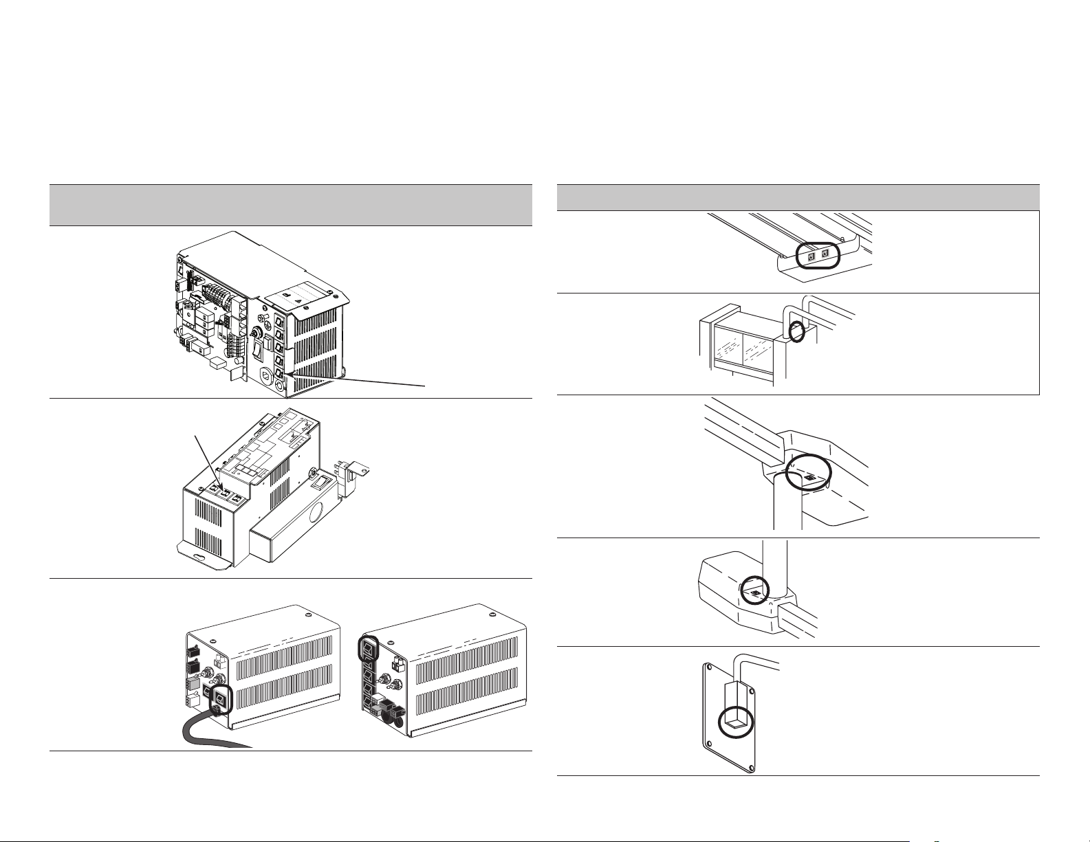
3
A-dec LED Dental Light Circuit Board Components
LED Driver Circuit Board Identification
Part Number: 43.0200.00
2
4
5
Item Description
1 J1 - 0~ terminal strip input
2 J1- 24~ terminal strip input
3 P1 - Data port
4 P4 - LED indicator board output connector
5 DS1 - Power LED
6 DS2 - Status LED
7 DS3 - Data LED
8 J2 - LED source board terminal strip
9 P2 - Down intensity switch connector
10 P3 - Up intensity switch connector
11 P5 - On/Off switch connector
CAUTION Circuit boards are sensitive to static electricity.
Electrostatic Discharge (ESD) precautions are required when
touching a circuit board or making connections to or from the
circuit board. Circuit boards should be installed only by an
electrician or qualied service person.
LED Dental Light Circuit Board Indicators
1
6
7
LED Status Description
Power LED Off No power, tripped circuit breaker, power supply
turned off, no line voltage
Green, steady
Status LED Off System is not functioning, no power or circuit
Green, steady
Data LED Off No DCS communication, not connected to the
Green, steady
Green, blinking
Power at terminal strip
board has failed
Normal operation
DCS, DCS has failed
Detects active DCS
Valid DCS message
11
10
8
9
Page 23

LED Array Board Indictors
Light Mode LED Array Board Status Description
Off All Array board LEDs off: device is
Off
Cure-safe
High
Medium
Low
Off
Yellow steady
Location
Off
White steady
Location
Off
White steady
Location
Off
White steady
Location
disconnected, no power, or circuit board has
failed
Cure-safe mode is off
Cure-safe mode is on
Four outer corners LEDs of array board
High mode is off
High mode is on
Eight inner LEDs of array board
Medium mode is off
Medium mode is on
Eight inner LEDs of LED array board
Low mode is off
Low mode is on
Eight inner LEDs of array board
LED Array
Board
86.0326.00 Rev C A-dec Dental Lights 21
Page 24

A-dec Dental Lights and Monitor Mounts A-dec Dental Lights 22
LED Dental Light Indicator Light Circuit Board Identification
Part Number: 43.0217.00
Item Description
1 P1 - Indicator board input connector
2 DS1 and DS2 - Cure-safe mode
3 DS3 and DS4 - High mode LEDs
4 DS5 and DS6 - Medium mode LEDs
5 DS7 and DS8 - Low mode LEDs
CAUTION Circuit boards are sensitive to static electricity.
Electrostatic Discharge (ESD) precautions are required when
touching a circuit board or making connections to or from the
circuit board. Circuit boards should be installed only by an
electrician or qualied service person.
LED Indicator Light Board Indictors
Light Mode Indicator Board Status Description
Off All indicator board LEDs off: device is
Off
Cure-safe
High
Medium
Low
Off
Yellow steady
Location
Off
Blue steady
Location
Off
Blue steady
Location
Off
Blue steady
Location
disconnected, no power, or circuit board has
failed
Cure-safe mode is off
Cure-safe mode is on
Top of indicator board
High mode is off
High mode is on
Top blue indicator
Medium mode is off
Medium mode is on
Middle blue indicator
Low mode is off
Low mode is on
bottom blue indicator
(Front)
1
2
(Back)
3
4
3
4
5
Page 25

LED Dental Light Terminal to CAN Adapter Board Identification
Part Number: 43.0236.00
Item Description
1 P1 - Data port
2 J1 - Data terminal strip
1
CAN Adaptor Board
Part Number: 43.0132.00
2
86.0326.00 Rev C A-dec Dental Lights 23
Page 26

A-dec Dental Lights and Monitor Mounts A-dec Dental Lights 24
A-dec LED Dental Light (570L — 577L) Wiring
571L on an A-dec 511 Chair
LED Indicator Light Circuit
Board
Page 27

571L on an A-dec 411 Chair
LED Indicator Light Circuit
Board
43.0363.00
86.0326.00 Rev C A-dec Dental Lights 25
Page 28

A-dec Dental Lights and Monitor Mounts A-dec Dental Lights 26
571L on an A-dec 311 Chair
Light Head
LED
Indicator
Light Circuit
Board
Support Center
Page 29

572L on an A-dec 511 Chair, Radius Arm Mounted
LED Indicator Light
Circuit Board
86.0326.00 Rev C A-dec Dental Lights 27
Page 30

A-dec Dental Lights and Monitor Mounts A-dec Dental Lights 28
574L Cabinet Mounted
LED Indicator Light
Circuit Board
Page 31

575L Wall Mounted
LED
Indicator
Light
Circuit
Board
86.0326.00 Rev C A-dec Dental Lights 29
Page 32

A-dec Dental Lights and Monitor Mounts A-dec Dental Lights 30
576L Ceiling Mounted
LED
Indicator
Light
Circuit
Board
Page 33

577L Track Mounted
LED Indicator Light Circuit Board
86.0326.00 Rev C A-dec Dental Lights 31
Page 34

A-dec Dental Lights and Monitor Mounts A-dec Dental Lights 32
15
A-dec 571/572 and 6300 Dental Light (Halogen 3-Axis) Circuit Board Components
A-dec 511 Chair Circuit Board
Part Number: 90.1072.00
16
1
14
17
20
11
12
13
18
21
2
4
3
5
6
571/572/6300 Dental Light Output Functions
Function K1 (DS8) K6 (DS7) Output
Off Off Off 0 VAC
High intensity On Off 17 VAC
Composite intensity Off On 12 VAC
Medium Intensity On On 16 VAC
10
19
9
8
7
Page 35

511 Chair Circuit Board Indicators
511 Chair Circuit Board Identification
LED Status Description
DS1 - AC power LED Off No 24 VAC power, tripped circuit breaker, power supply
turned off, no line voltage
Green,
steady
DS2 - Status LED Off System is not functioning, no power or circuit board has
Green,
steady
DS3 - Data LED Off No DCS communication, not connected to the DCS, or DCS
Green,
steady
Green,
blinking
DS4 - Chair limit switch Off Closed, (normal)
Red
DS13 - Chair lockout Off Open, (normal)
Red
DS5 + DS6 - Chair
potentiometers
DS9, DS10, DS11, DS12
- Chair relay LEDs
DS7, DS8 - Dental light
relay LEDs
DS14 - Vacuum relay LED Off Relay is off
Off Potentiometer: Not connected or bad connection; moving in
Yellow,
steady
Yellow, fast
blink
Off Relay is off
On Relay is on
Off Relay is off
On Relay is on
On Relay is on
24 VAC at the terminal strip
failed
Normal operation
has failed
Detects active DCS
Valid DCS message
Open, (activated)
Closed, (activated)
wrong direction; limited range of motion; or cable is not on
wheel.
Normal operation
Upper end of travel
Item Description
1 P7, P8, P9 - Data line ports
2 DS4 - Stop switch LED (limit switch) and P10 connector
3 DS5 - Back potentiometer LED and P1 connector
4 DS6 - Base potentiometer LED and P2 connector
5 P5 - Footswitch connector
6 P3 - Test points
7 DS12 - Base down LED and relay K5
8 DS11 - Base up LED and relay K4
9 DS10 - Back down LED and relay K3
10 DS9 - Back up LED and relay K2
11 DS1 - AC power LED
12 DS2 - Status LED
13 DS3 - Data LED
14 DS13 - Chair lockout LED and terminal strip J1
15 J2 - Ø VAC terminal strip (output)
16 J2 - 24 VAC terminal strip (output)
17 P4 - Input power and dental light connector
18 J3 - Vacuum relay K7 output terminal strip
19 P11 - Pump motor and solenoid connector
20 DS8 - Dental light LED relay and K1
21 DS7 - Dental light LED relay and K6
CAUTION Circuit boards are sensitive to static electricity.
Electrostatic Discharge (ESD) precautions are required when
touching a circuit board or making connections to or from the
circuit board. Circuit boards should be installed only by an
electrician or qualied service person.
86.0326.00 Rev C A-dec Dental Lights 33
Page 36

A-dec Dental Lights and Monitor Mounts A-dec Dental Lights 34
1
A-dec 6300 Dental Light Relay Circuit Board
Part Number: 28.1577.00
2
3
7
8
6
9
4 5
6300 Dental Light Output Functions
Function K1 (DS4) K2 (DS5) Output
Off Off Off 0 VAC
High intensity On Off 17 VAC
Composite intensity Off On 12 VAC
Medium Intensity On On 16 VAC
Page 37

6300 Dental Light Relay Circuit Board LED Indicators
6300 Dental Light Relay Circuit Board Identification
LED Status Description
DS1 - AC power
LED
DS2 - Status LED Off System is not functioning, no power or
DS3 - Data LED Off No DCS communication, not connected to
DS4, DS5 - Dental
light relay LEDs
Off No 24 VAC power, tripped circuit breaker,
power supply turned off, no line voltage
Green, steady 24 VAC at P1 input power connector
circuit board has failed
Green, steady Normal operation
the DCS, or DCS has failed
Green, steady Detects active DCS
Green, blinking Valid DCS message
DS4, DS5
Off, Off Dental light off
On, Off High intensity
Off, On Composite intensity
On, On Medium intensity
Item Description
1 DS1 - AC power LED
2 DS2 - Status LED
3 DS3 - Data LED
4 DS4 - Dental light relay
5 DS5 - Dental light relay
6 P1 - Input power
7 P2 - Data line port
8 J1 - Toggle switch inputs
9 J2 - Dental light output power
CAUTION Circuit boards are sensitive to static electricity.
Electrostatic Discharge (ESD) precautions are required when
touching a circuit board or making connections to or from the
circuit board. Circuit boards should be installed only by an
electrician or qualied service person.
86.0326.00 Rev C A-dec Dental Lights 35
Page 38

A-dec Dental Lights and Monitor Mounts A-dec Dental Lights 36
A-dec 571/572 and 6300 Dental Light (Halogen 3-Axis) Wiring
6300 Ceiling, Wall, and Preference Mount Switch and Data Line Connections
Switch and Bulb
Connections
6300 Dental Light Circuit Board
Page 39

6300 Track Light Switch Connections and Data Line (2004 and Later)
6300 Light Circuit Board
Switch and Bulb
To Chair Circuit Board
86.0326.00 Rev C A-dec Dental Lights 37
Connections
Page 40

A-dec Dental Lights and Monitor Mounts A-dec Dental Lights 38
6300 Track Light Switch Connections and Data Line (2003 and Earlier)
To Chair
Circuit Board
6300 Light
Circuit Board
Page 41

86.0326.00 Rev C A-dec Dental Lights 39
Page 42

A-dec Dental Lights and Monitor Mounts A-dec Dental Lights 40
A-dec 571/572 and 6300 Dental Light (Halogen 3-Axis) Transformer
Part Number: p/n 28.1588.00
The transformer is wired three different ways to create 100 VAC, 110-120 VAC, and 220-240 VAC voltages.
100 VAC Transformer Wiring 110-120 VAC Transformer Wiring
Page 43

220-240 VAC Transformer Wiring
86.0326.00 Rev C A-dec Dental Lights 41
Page 44

A-dec Dental Lights and Monitor Mounts A-dec Dental Lights 42
43.0363.00
16
14
26
A-dec 371/372 Dental Light (Halogen 2-Axis) Circuit Board Components
A-dec 311/411 Dental Chair Circuit Board for 371/372 Dental Light on an A-dec 311 and 411 Chair
NOTE Beginning July 2013: Jumpers are required on P10 and P13 for the 311 chair.
31 & 32
30
3
20
4
1
5
18
24
25
13
27
19
2
21
11
23
22
8
12
9
15
17
28
29
6
10
7
Page 45

311/411 Chair Circuit Board LED Indicators
311/411 Chair Circuit Board Identification
LED Status Description
DS1, DS14, and
DS15 - AC power
LED
DS2 and DS16Status LED
DS3 - Data LED Off No DCS communication, not connected to
DS13 - Chair lockout Off Open, (normal)
DS5, DS6 - Chair
position sensors
DS9, DS10, DS11,
DS12, DS17- Chair
relay LEDs
DS7, DS8 - Dental
light relay LEDs
Off No 24 VAC power, tripped circuit breaker,
power supply turned off
Green, steady 24 VAC at P1 input power connector
Off System is not functioning, no power, or
circuit board has failed
Blue, steady
Blue, single blink
Blue, double blink
Green, steady
Green, blinking
Red, on
Off Position Sensor: not connected or bad
Yellow, steady
Yellow, fast blink
Yellow, slow blink
Off Relay is off
On Relay is on
Off Relay is off
On Relay is on
Normal operation
Duty cycle limit of chair back has been
exceeded
Jumper is in factory mode
the DCS, or DCS has failed
Detects active DCS
Valid DCS Message
Closed, (activated)
connection; moving in wrong direction;
limited range of motion
Normal operation
Upper end of travel
Lower end of travel
Item Description Item Description
1 DS1 - AC power LED (CB1) 17 P4 - input power connector
2 DS2, DS16 - status LEDs 18 P5 - touchpad or footswitch connector
3 DS3 - data LED 19 P6/P7 - data ports
4 DS5 - back position sensor, LED/
P1 Connector
5 DS6 - base position sensor LED/
P2 connector
6 DS7 - dental light LED/Relay K6 22 P11 - base motor connector
7 DS8 - dental light LED/Relay K1 23 P12 - input power connector
8 DS9 - back up LED/Relay K2 24 J1 - Ø VAC terminal strip (output) for
9 DS10 - back down LED/relay K3 25 J2 - 24 VAC terminal strip (output) for
10 DS11 - base up LED/relay K4 26 J3 - 0 VAC terminal strip (output) for
11 DS12 - base down LED/relay K5 27 J3 - 24 VAC terminal strip (output) for
12 DS13 - chair lockout LED/terminal
strip J4
13 DS14 - AC power LED (CB4) 29 J6 - dental light input terminal strip
14 DS15 - AC power LED (CB5) 30 J7 - base solenoid terminal strip
15 DS17 - back on LED/Relay K7 31 P10 - Jumper - 311 chair only
16 P3 - testpoints header 32 P13 - Jumper - 311 chair only
20 P8 - back motor connector
21 P9 - input power connector
assistant’s, doctor’s, oor box
assistant’s, doctor’s and oor box
support center
support center
28 J5 - dental light output terminal strip
CAUTION Circuit boards are sensitive to static electricity.
Electrostatic Discharge (ESD) precautions are required when
touching a circuit board or making connections to or from the
circuit board. Circuit boards should be installed only by an
electrician or qualied service person.
86.0326.00 Rev C A-dec Dental Lights 43
Page 46

A-dec Dental Lights and Monitor Mounts A-dec Dental Lights 44
20
A-dec 511 Chair Board Components for 371/372 Dental Light on an A-dec 511 Chair
16
14
17
15
1
11
12
13
18
21
10
2
4
3
5
371/372 Dental Light Output Functions
Function K1 (DS8) K6 (DS7) Output
Off Off Off 0 VAC
High intensity On Off 17 VAC
Composite intensity Off On 12 VAC
6
7
19
9
8
Page 47

511 Chair Circuit Board LED Indicators
511 Chair Circuit Board Identification
LED Status Description
DS1 - AC power
LED
DS2 - Status LED Off System is not functioning, no power or circuit
DS3 - Data LED Off No DCS communication, not connected to the
DS4 - Chair limit
switch
DS13 - Chair
lockout
DS5 + DS6 Chair
potentiometers
DS9, DS10,
DS11, DS12 Chair relay LEDs
DS7, DS8 Dental light relay
LEDs
DS14 - Vacuum
relay LED
Off No 24 VAC power, tripped circuit breaker, power
supply turned off, no line voltage
Green, steady
Green, steady
Green, steady
Green, blinking
Off Closed, (normal)
Red
Off Open, (normal)
Red
Off Potentiometer: Not connected or bad connection;
Yellow, steady
Yellow, fast blink
Off Relay is off
On Relay is on
Off Relay is off
On Relay is on
Off Relay is off
On Relay is on
24 VAC at the terminal strip
board has failed
Normal operation
DCS, or DCS has failed
Detects active DCS
Valid DCS message
Open, (activated)
Closed, (activated)
moving in wrong direction; limited range of motion;
or cable is not on wheel
Normal operation
Upper end of travel
Item Description Item Description
1 P7, P8, P9 - data ports 11 DS1 - AC power LED
2 DS4 - stop switch LED (limit
switch)/P10 connector
3 DS5 - back potentiometer LED/P1
connector
4 DS6 - base potentiometer LED/P2
connector
5 P5 - footswitch connector 15 J2 - 0 VAC terminal strip (output)
6 P3 - testpoints header 16 J2 - 24 VAC terminal strip (output)
7 DS12 - base down LED/relay K5 17 P4 - Input power/dental light
8 DS11 - base up LED/relay K4 18 J3 - vacuum relay K7 output terminal
9 DS10 - back down LED/relay K3 19 P11 - pump motor/solenoid
10 DS9 - back up LED/relay K2 20 DS8 - dental light LED relay/K1
12 DS2 - status LED
13 DS3 - data LED
14 DS13 - chair lockout LED/terminal
strip J1
connector
strip
connector
21 DS7 - dental light LED relay/K6
CAUTION Circuit boards are sensitive to static electricity.
Electrostatic Discharge (ESD) precautions are required when
touching a circuit board or making connections to or from the
circuit board. Circuit boards should be installed only by an
electrician or qualied service person.
86.0326.00 Rev C A-dec Dental Lights 45
Page 48

A-dec Dental Lights and Monitor Mounts A-dec Dental Lights 46
A-dec 371/372 Dental Light Relay Circuit Board
2
1
3
7 8 6
4
5
371/372 Dental Output Functions
9
Function K1 (DS4) K2 (DS5) Output
Off Off Off 0 VAC
High intensity On Off 17 VAC
Composite intensity Off On 12 VAC
Page 49

371/372 Dental Light Relay Board LED Indicators
371/372 Dental Light Relay Circuit Board Identification
LED Status Description
DS1 - AC power
LED
DS2 - Status LED Off System is not functioning, no power or circuit
DS3 - Data LED Off No DCS communication, not connected to the
DS4, DS5 Dental light
relay LEDs
Off No 24 VAC power, tripped circuit breaker,
power supply turned off, no line voltage
Green, steady 24 VAC at the terminal strip
board has failed
Green, steady Normal operation
DCS, or DCS has failed
Green, steady Detects active DCS
Green, blinking Valid DCS message
DS4, DS5
Off, Off Dental light off
On, Off High intensity
Off, On Composite intensity
On, On Medium intensity
Item Description
1 DS1 - AC power LED
2 DS2 - Status LED
3 DS3 - Data LED
4 DS4 - Dental light relay
5 DS5 - Dental light relay
6 P1 - Input power
7 P2 - Data port
8 J1 - Toggle switch inputs
9 J2 - Dental light output power
CAUTION Circuit boards are sensitive to static electricity.
Electrostatic Discharge (ESD) precautions are required when
touching a circuit board or making connections to or from the
circuit board. Circuit boards should be installed only by an
electrician or qualied service person.
86.0326.00 Rev C A-dec Dental Lights 47
Page 50

A-dec Dental Lights and Monitor Mounts A-dec Dental Lights 48
371/372 and 571L/572L Wiring on the 311 and 411 Chair Board
571L & 572L LED Light
Jumpers Required
On 311 Only In
P10 And P13
(371 Dental Light)
(571 - 300 Dental Light)
Page 51

A-dec 371/372 Dental Light (Halogen 2-Axis) Wiring
371/372 Dental Light Connections
TIP Any DCS enabled touchpad connected to a light’s DCS system
will activate the dental light function.
On/Off Switch
The on/off switch is used to manually turn on or off the dental light from the
light head. The replacement kit is p/n 90.1039.00.
Position Voltage Wire
Open 5 VDC White
Closed 0 VDC White
371/372 Dental Light Switch Connections
371/372 Light (Before September 2011)
NOTE All DC voltage measurements are taken with the black
multimeter lead on the black/white wire.
86.0326.00 Rev C A-dec Dental Lights 49
371/372 Lights (Effective September 2011)
Page 52

A-dec Dental Lights and Monitor Mounts A-dec Dental Lights 50
43.0363.00
A-dec 371/372 Dental Light Wire Connections on an A-dec 311 Chair
Terminal Voltage Terminal Label Wire
J5 17/12.1 VAC VIO Violet
J5 0 VDC BLK Black
J5 Dental Light Output
(Violet)
(Black)
(Black/White)
(White)
Light Cable
Page 53

A-dec 371/372 Dental Light Wire Connections on an A-dec 511 Chair
PIN Voltage Terminal Label Wire
5 17/12.1 VAC VIO Violet
2 0 VAC BLK Black
6 0/5 VAC WHT White
1 0 VAC BLK/WHT Black with white stripe
Light Cable
86.0326.00 Rev C A-dec Dental Lights 51
Page 54

A-dec Dental Lights and Monitor Mounts A-dec Dental Lights 52
A-dec 371/372 Dental LIght Wire Connections on Cascade, Decade, Performer, Priority Chairs
Terminal Voltage Terminal Label Wire
J2 17/12.1 VAC VIO Violet
J2 0 VAC BLK Black
372 Dental LIght
J1 0 VDC (circuit ground) BLK/WHT Black/White
J1 5 VDC = on/off toggle = open
0 VDC = on/off toggle = closed
J1 5 VDC = medium or composite
0 VDC = high out
J1 5 VDC = high or medium
0 VDC = composite
J2 17/16/12.1 VAC VIO Violet
J2 0 VAC BLK Black
WHT White (On/Off)
BlU Blue
YEL Yellow (composite)
300W Power Supply
Power Supply LED
Indicator Connection
NOTE The LED indicator must be connected to the power supply for the dental light circuit board to function correctly.
LED Indicator
Light
372
Dental Light
PCB
Support Center
Data Line
Light Cable
Page 55

86.0326.00 Rev C A-dec Dental Lights 53
Page 56

A-dec Dental Lights and Monitor Mounts A-dec Dental Lights 54
Dental Light Troubleshooting
This table contains tips and troubleshooting information to assist you in diagnosing dental light problems. This table is not intended to cover every situation, but
includes the most common problems that you may encounter.
LED (570L - 577L), 371, 372, 571, 572, 6300 Troubleshooting
Problem Possible Cause Description
Light does not work (light
connected to 311 chair circuit
board).
The bulb has failed (non-LED
dental lights).
The dental light circuit
breaker, CB6, has been
tripped or the power supply
has failed.
Check for voltage at the bulb socket, if voltage is present, replace the bulb.
Check the color of the bulb, replace if discolored.
• Check the circuit breaker and reset it. If the circuit breaker trips again, disconnect P4, J5, and J6 on the 311 chair board. If
the circuit breaker trips again, replace the power supply.
• If the circuit breaker does not trip, reconnect P4. If the circuit breaker now trips, replace the 311 chair circuit board.
• If the circuit breaker does not trip, reconnect the connections to J6 (if any). If the circuit breaker now trips, replace the
switch wiring to the 571-300 dental light.
• If the circuit breaker does not trip, reconnect the connections to J5. If the circuit breaker trips, replace the dental light.
371 or 372 Dental Lights on a 511 chair:
• If CB5 on the 300 W power supply is tripped, disconnect the dental light connector at the power supply and reset the
circuit breaker. If CB5 trips again, replace the power supply. Connect the dental light to the power supply, if CB5 trips,
replace the dental wiring harness or the adapter cable wiring.
371 or 372 Dental Lights NOT on a 511 or 311 chair:
• If the dental light circuit breaker on the 300 W power supply is tripped:
• Disconnect the dental light connector at the power supply and reset the circuit breaker.
• If the circuit breaker trips again, replace the power supply. (Connect the dental light to the power supply.) If the circuit
breaker trips, either the dental light wiring harness, switch wiring, dental light circuit board, or dental light circuit
board power cable has failed. Connect one at a time to determine the location of the failure.
571 Dental Lights:
• If CB5 on the 300 W power supply is tripped, disconnect the dental light and reset the circuit breaker. If CB5 trips gain,
replace the power supply. Connect the dental light to the power supply and if CB5 trips, the dental light wiring harness or a
switch is faulty.
572 Dental Lights:
• The dental light circuit breaker is near the power transformer. If the breaker is tripped, disconnect the dental light wiring
harness from the transformer and reset the breaker. If the breaker trips again, reset the circuit breaker. If the breaker
does not trip, the dental wiring harness or a switch is faulty.
The bulb socket is faulty
(non-LED dental lights).
Replace the socket.
Page 57

Problem Possible Cause Description
Light works from the
touchpad(s) but not from the
dental light switches.
Light works from the dental
light switches.
Loose connection in the
dental light wiring harness.
Faulty data line from the
touchpad to the circuit board.
Verify that the wiring is connected properly.
Check the connections at the dental light switches and terminals H5 and H6 on the circuit board.
Temporarily substitute a known good data line from the touchpad to the circuit board, if the light works from the touchpad,
determine and replace any bad bypassed data lines.
Light head is loose or difcult
to position.
Flexarm drifts. Tension adjustment nut inside
Track light trolley drifts. Track is not level. Use wedges to level the track light ceiling pallet (p/n 017.017.00).
Track trolley light bounces
back when pushed to the end
of the track.
Light intensity is dim,
inconsistent, or the color is
distorted.
Unsatisfactory light pattern. Light is out of focus, reector
Rotation tension screws are
too loose or tight.
the exarm is too loose or
tight.
Power cable is hanging up
inside the track.
Reector or light shield may be
damaged (non-LED dental
light).
For the 372 Dental Light, the
intensity switch is in the
medium or composite
position.
The mains voltage is low. Verify the mains voltage is within specications: 100/110-120/220-240 VAC
Adjust the appropriate axis tension.
Adjust the exarm counterbalance.
Check power cable in track for proper routing. If you cannot correct the routing of the cable, replace the cable assembly.
Inspect the dental light shield and reector for damage or contamination. Replace or clean as necessary.
CAUTION: Abrasives, disinfectants or chlorine damage the shield and reector. Refer to the Instructions for Use for cleaning
instructions.
Check the intensity switch position.
NOTE: Turning the light on when the intensity switch is in the composite position results in medium intensity.
1. Focus the light.
or light shield may be
damaged (non-LED dental
lights).
2. Check the light shield for severe abrasions, and replace if necessary.
3. Clean the reector and light shield.
86.0326.00 Rev C A-dec Dental Lights 55
Page 58

A-dec Dental Lights and Monitor Mounts A-dec Dental Lights 56
Page 59

A-dec Monitor Mounts
581 Side Mounted
(fomerly 561 Monitor Mount)
584 Cabinet Mounted
382 Radius Mounted
585 Wall Mounted
482 Radius Mounted
587 Cabinet Track Mounted
586 Ceiling Mounted
86.0326.00 Rev C A-dec Monitor Mounts 57
Page 60

A-dec Dental Lights and Monitor Mounts A-dec Monitor Mounts 58
Monitor Mount Specifications and Adjustments
Monitor Mount Specifications
Maximum Monitor Weight:
31 lb (14.1 kg) for models 382, 584, 585 586,
20 lb (9.1 kg) for models 381, 482 , 581, 587
Recommended Maximum Monitor Size:
19” (482 mm) diagonal
NOTE A-dec monitor mounts are VESA (Video Electronics
Standards Association) compliant, so they support most monitor
brands and sizes.
NOTE A-dec monitor mounts are intended to support and position
a medical grade or equivalent flat-panel monitor.
NOTE Specifications are subject to change without notice. Some
requirements may vary from country to country. For more
information, contact your authorized A-dec dealer..
Monitor Mount Adjustments
A-dec monitor mounts use one of the following positioning mechanisms:
Floating
These mounts provide continuous tension which holds the monitor in place
after it is positioned.
Locking
These mounts include a handle that allows you to manually lock the tilt
position of the monitor.
Page 61

Style 1, Floating
Style 2, Floating
Upward
Tension
Turn the hex key clockwise to increase the tension.
Style 3, Floating
Use a 1/8"
Hex Key
3/16"
Hex Key
5/32"
Hex Key
Downward
Tension
5/32"
Hex Key
Turn the hex key clockwise to increase the tension. This adjustment may be necessary for
both the upward and downward tension.
Style 4, Locking
Turn the handle clockwise to lock the monitor position.
Use a 1/8" hex key to remove the back cover screws. Use a 5/32" hex key to increase or
decrease the mount's vertical tension.
(Note: The handles may be repositioned after the cover is removed. Use a 1/8" hex key to remove and
replace the handle screws.)
86.0326.00 Rev C A-dec Monitor Mounts 59
Page 62

A-dec Dental Lights and Monitor Mounts A-dec Monitor Mounts 60
Tray Holder Tension Adjustment (581)
The tension adjustment screw for the tray holder is located in the hub of the
tray holder arm.
1. Locate the small hole in the tray holder hub, and insert a 5/32” hex key
through the hole.
2. Rotate the tray support arm to adjust the tension (right to increase tension,
left to decrease tension).
Tray Holder
Hub
Hole
5/32” Hex Key
Panning Friction Adjustment (587)
Use a 3/16” hex key to tighten or loosen the panning friction adjustment
screw on the track mount until it freely rotates.
Screw Adjusts
Horizontal Rotation
Page 63

Page 64

A-dec Headquarters
2601 Crestview Drive
Newberg, Oregon 97132
United States
Tel: 1.800.547.1883 within USA/CAN
Tel: +1.503.538.7478 outside USA/CAN
Fax: 1.503.538.0276
www.a-dec.com
A-dec Australia
Unit 8
5-9 Ricketty Street
Mascot, NSW 2020
Australia
Tel: 1.800.225.010 within AUS
Tel: +61.(0).2.8332.4000 outside AUS
A-dec China
A-dec (Hangzhou) Dental Equipment Co., Ltd.
528 Shunfeng Road
Qianjiang Economic Development Zone
Hangzhou 311106
Zheijiang, China
Tel: +1.503.538.7478
A-dec United Kingdom
EU Authorized Representative
Austin House, 11 Liberty Way
Nuneaton, Warwickshire CV11 6RZ
England
Tel: 0800.ADEC.UK (2332.85) within UK
Tel: +44.(0).24.7635.0901 outside UK
ÍvÈ.Ç#:È.00XÎ
86.0326.00 Rev C
Copyright 2014 A-dec Inc.
All rights reserved.
 Loading...