

Page 1

85.0812.00, 2003 LI-1
Dental Lights Overview
This section presents the Pre-Cascade and Cascade dental lights and their specifications.
Detail on how to service and adjust lights and troubleshoot specific problems is presented.
For more information on service parts, see the Genuine A-dec Service Parts Catalog or contact
customer service.
If you are looking for information about the Performer dental light, please see Performer (PR).
Page 2
85.0812.00, 2003
Dental Lights Serial/Model Number Label
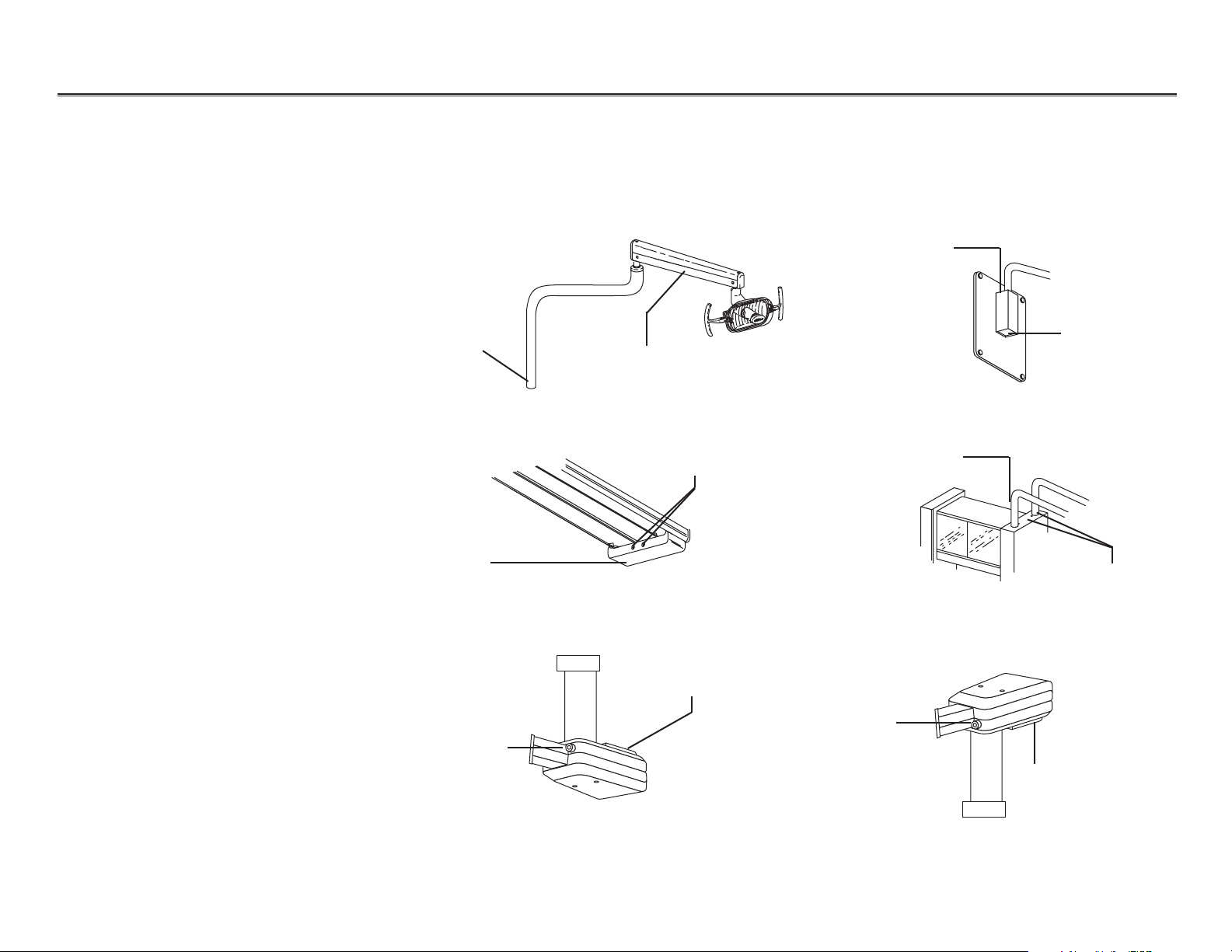
Locating Model/
Serial Number and
Circuit Breakers
Unit Mount and Radius Lights
Model/serial number
tag (bottom of post
after June 1998)
Model/serial number tag
(under cover before June 1998)
Track Light
Model/serial number tag
(on back of cover)
Circuit breakers
Ceiling Light
Wall Mount
Model/serial number
tag (on top of cover)
Model/serial number
tag (on top of cover)
Circuit breaker
Circuit breaker
(hidden)
Preference
Post Mount
Model/serial number
tag (at base of arm)
Circuit breaker(s)
Model/serial number tag
(on bottom of cover)
Circuit breaker
The model/serial number tags identify the light model and manufacture date. If you have
difficulty locating the model/serial number or circuit breaker locations on the lights,
the following examples may be helpful. The circuit breakers automatically interrupt the flow of
electricity to the light if an over-current condition occurs.
NOTE:Circuit breakers (post June
1998) and fuses (before
June 1998) are located in
the power supply.
LI-2
®
Page 3
85.0812.00, 2003 LI-3
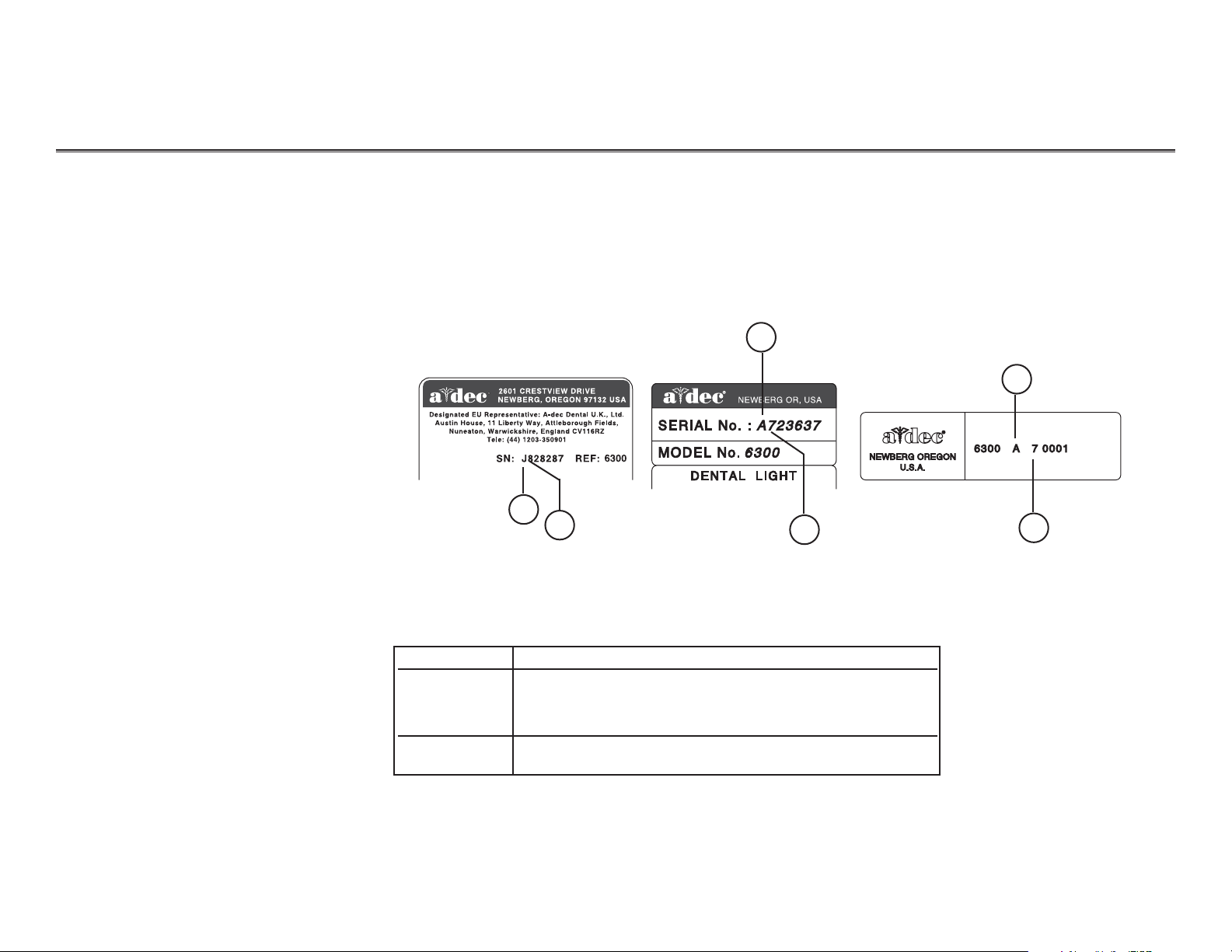
Dental Lights Manufacture Dates
Serial/Model Number Label
Reading
Manufacture Dates
1
1
1
2
2
2
Item # Description
1 Month of manufacture
The first letter of the serial number indicates the month
the product was manufactured; e.g., A is January.
2 Last digit of the year manufactured, e.g., 7 is 1997
Different versions of the light can be distinguished by month and year manufactured. This
information is included in the serial number of each dental light.
The following examples show how to identify the month and year in which a light was manufactured.
Page 4
85.0812.00, 2003 LI-4
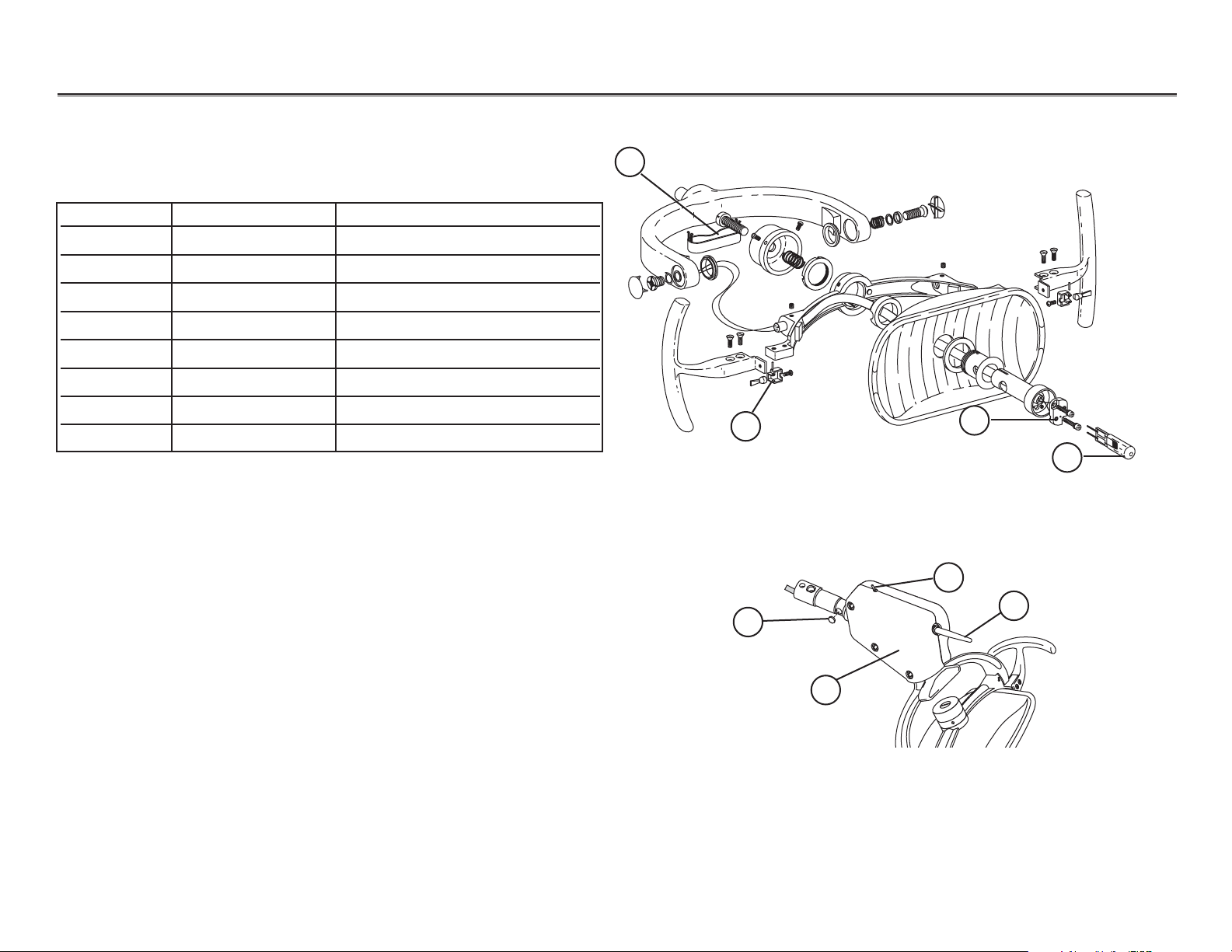
Dental Lights Cascade Light Head
Item # Part Number Description
1 28.1004.00 Bulb and holder
2 041.179.01 Bulb
3 90.0463.01 Lamp socket kit
4 28.1012.00 Bracket assembly (2 required)
5 28.0679.01 Pivot stop
6 90.1043.00 Intensity switch kit
7 90.1039.00 On/Off switch kit
8 28.1464.01 Switch housing kit
Cascade Light Head
6
A
1
2
5
V
A
C
3
A
2
50
V
A
C
O
N
O
N
O
N
Cascade Light Head
1
5
2
3
Cascade Light Head
4
6
7
8
6
A
1
2
5
V
A
C
3
A
2
5
0
V
A
C
O
N
O
N
O
N
Page 5
85.0812.00, 2003 LI-5
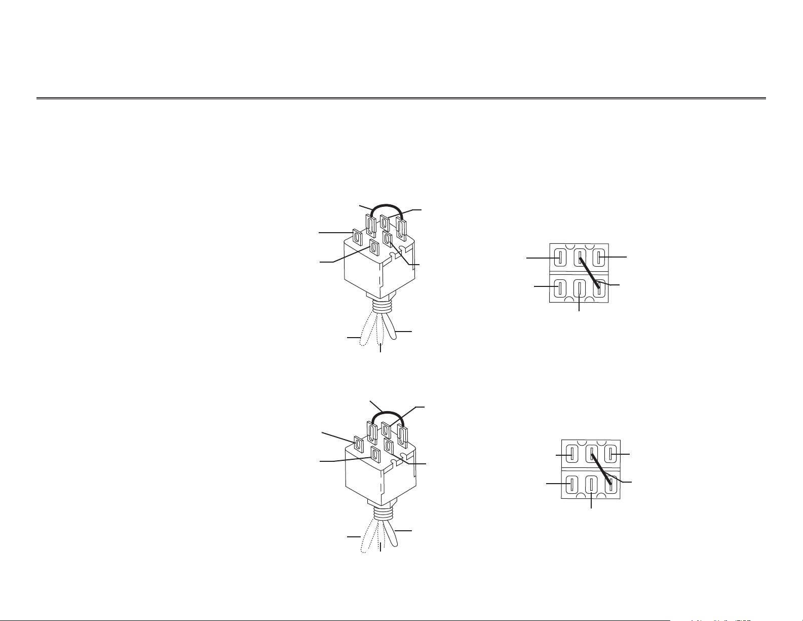
Dental Lights Cascade
After September 1998
Before September 1998
Identifying Intensity
Switch Connections
(Cascade)
Blue
Violet
White
Low
High
Medium
Green
Blue
(15-16vac)
Violet
(16-17vac)
Green
(14-15vac)
White
Jumper wire
Red
Wht
Blk
Low
High
Medium
Brn
Red
(15-16vac)
White
(16-17vac)
Brown
(14-15vac)
Black
Jumper
wire
The three-position intensity switch is used to set light intensity at one of three settings: low,
medium, or high. The replacement kit for the intensity switch is P/N 90.1043.00.
The following illustrations identify the connections for attaching appropriate wires from the
intensity switch to the dental light.
Jumper
wire
Jumper
wire
Page 6
85.0812.00, 2003
LI-6
Dental Lights Cascade Wiring Diagrams
After September 1998
Wiring Transformer,
(110-120 VAC, 240 VAC)
Transformer
Before September 1998
Transformer
NOTE: The power transformer had lower output voltages and no “1 VAC” tap before January 1989.
The transformer converts incoming source power to the correct voltage to power the dental light
head. The wiring diagram shows the wiring changes for the transformers.
17 VAC
16 VAC
15 VAC
1 VAC
0 VAC
17 VAC
16 VAC
15 VAC
1 VAC
0 VAC
Page 7
85.0812.00, 2003 LI-7
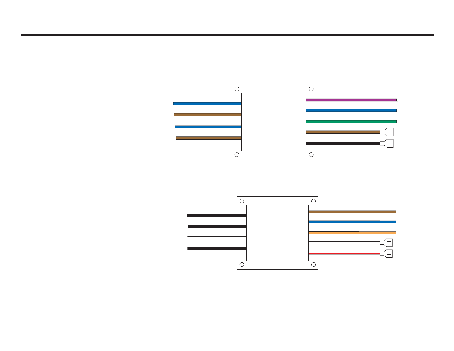
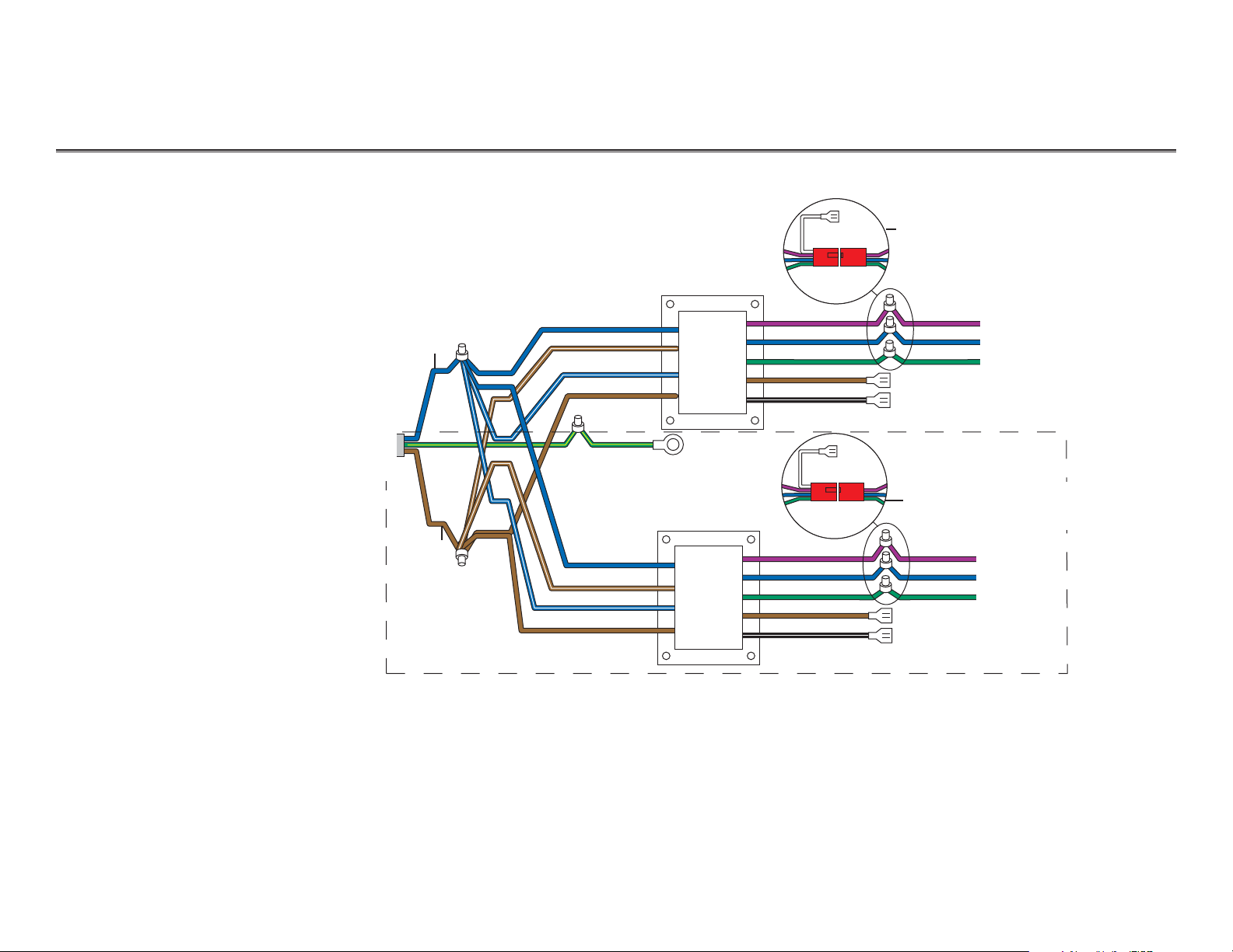
Dental Lights Cascade Wiring Diagram
Wall-Mount, Single/Dual
Track, Preference, and
Ceiling-Mounted Lights
NOTE:Voltages shown are assuming 120/240 VAC. Secondary voltages
measured without the lamp inserted will register 1.2 VAC higher.
After September 1998
(Wht in Pref)
(Blk in
Pref)
(Grn in
Pref)
Transformer
Transformer
To
power
source
To circuit breaker
To light head
To circuit
breaker
To light head
Wall-mounted and
Preference-mounted lights
Wall-mounted and
Preference-mounted lights
Dual track light (optional)
17 VAC
16 VAC
15 VAC
1 VAC (not used)
0 VAC
17 VAC
16 VAC
15 VAC
0 VAC
1 VAC (not used)
Page 8

85.0812.00, 2003 LI-8
Dental Lights Cascade Wiring Diagram
Wall-Mount, Single/Dual
Track and Preference
Mounted Lights
NOTE:Voltages shown are assuming 120/240 VAC. Secondary voltages
measured without the lamp inserted will register 1.2 VAC higher.
January 1989 to September 1998
Transformer
Transformer
To
power
source
To circuit
breaker
Wall-mounted and
Preference-mounted lights
Wall-mounted and
Preference-mounted lights
17 VAC
16 VAC
15 VAC
1 VAC (not used)
0 VAC
(Wht in Pref)
(Blk in Pref)
(Grn in
Pref)
17 VAC
16 VAC
15 VAC
1 VAC (not used)
0 VAC To circuit breaker
To light head
To light head
Page 9

85.0812.00, 2003 LI-9
Dental Lights Cascade Wiring Diagram
Cascade Unit and
Radius-Mounted Lights
NOTE:Voltages shown are assuming 120/240 VAC. Secondary voltages
measured without the lamp inserted will register 1.2 VAC higher.
After May 1998
300-watt
power supply
Lower cable
assembly
Upper cable
assembly
Lamp
(17VAC)
(16VAC)
(15VAC)
Red 6-pin
connector
Intensity
switch
On/Off
switch
Page 10

85.0812.00, 2003 LI-10
Dental Lights Cascade Wiring Diagram
F10
DENTAL LIGHT
10A TIME DELAY
F8
BLK
BRN
RED
ORA
YEL
15V
17V
RETURN
16V
T4
DENTAL
LIGHT
BLK/
RETURN
CONTROL
HEAD
AUXILIARY
H5
300W before May 1998
BRN REDORA YELBLUWHI WHI/RD
BRN
ORA
0 VOLT
F3
F2
MADE IN USA
T1 DENTAL
LIGHT
BLK
BRN
RED
WHI
0 V
15 V
16 V
17 V
6V FUSE
5A 250V SB
A-DEC 41-1224-00
REV B
TO DECREASE LIGHT
BRIGHTNESS, PLACE
FUSE IN 1 VOLT SLOT
F1 10A 32V SB
150W before May 1998
Cascade Unit and
Radius-Mounted Lights
NOTE:Voltages shown are assuming 120/240 VAC. Secondary voltages
measured without the lamp inserted will register 1.2 VAC higher.
Grn/Yel
0 Volts
15 Volts
16 Volts
17 Volts
Ground
0 Volts
15 Volts
16 Volts
17 Volts
Ground
Grn/Yel
1 VOLT
Page 11

85.0812.00, 2003 LI-11
Dental Lights Pre-Cascade
March 1985 to October 1987
2
3
4
5
October 1987 to February 1994
1
3
4
5
Item # Part Number Description
1 28.0704.00 Bulb with holder
2 041.179.01 Bulb
3 90.0463.01 Lamp socket kit
4 28.0545.01 Pivot stop
5 90.0372.00 Light switch service kit
6 28.1012.00 Lens bracket assembly
(2 required)
Pre-Cascade Lights
Page 12

85.0812.00, 2003
Dental Lights Pre-Cascade
LI-12
Blue
Brown
Black
Low
High
Medium
Orange
Blue
(15-16vac)
Violet
(16-17vac)
Green
(14-15vac)
White
Jumper
Jumper
Identifying Intensity
Switch Connections
(Pre-Cascade)
The illustration identifies the intensity switch connections for Pre-Cascade units.
Page 13

85.0812.00, 2003
Dental Lights Pre-Cascade Wiring Diagram
LI-13
Wall-Mount, Single/Dual
Track and PreferenceMounted Lights
NOTE:Voltages shown are assuming 120/240 VAC. Secondary voltages measured
without the lamp inserted will register 1.2 VAC higher.
Before January 1989
Transformer
Transformer
To
power
source
To circuit breaker
To light head
To circuit breaker
To light head
(Grn in Pref)
17 VAC
15 VAC
17 VAC
16 VAC
15 VAC
1 VAC (not used)
0 VAC
1 VAC (not used)
0 VAC
16 VAC
Page 14

85.0812.00, 2003
Dental Lights Pre-Cascade Wiring Diagram
LI-14
Post, Ceiling, and
Excellence-Mounted Lights
Before January 1989
To power source
Transformer
To light
head
To circuit
breaker
(not
used)
Page 15

85.0812.00, 2003
Dental Lights Adjustments
LI-15
Adjusting
Diagonal and
Horizontal Tension
Adjusting Vertical
Tension
Focusing the
Light
To adjust diagonal movement, use a 5/32" hex key to turn the
adjustment screw at the bottom of the switch housing. Eliminate
all movement in the diagonal axis by tightening the screw until
it stops.
To adjust horizontal movement, use a 5/32" hex key to turn the
adjustment screw at the top of the switch housing.
To adjust vertical movement, use a 5/64" hex key to loosen the
setscrew on the right side of the light head. Remove the end cap.
Use a large flat-blade screwdriver to turn the adjustment screw
under the end cap. If the light head moves too easily, or tends to
drift out of position, increase the tension by turning the screw
clockwise. When the desired tension is achieved, reinstall the end
cap and retighten the setscrew.
The focus of the light is adjusted at the factory for proper
illumination at 27" from the oral cavity. If the light requires
focusing to suit the user’s style of practice, place a white towel
over the chair headrest and position the light at the distance from
the towel required by the user. Using a large screwdriver or coin,
turn the focus adjusting screw until the light pattern is uniform
in brightness without shadowing. The range of adjustment is
18" to 31".
Diagonal
adjustment
screw
Diagonal adjustment screw
Horizontal
adjustment
screw
End cap
5/64" hex key
Focus
adjustment
screw
Standard
screwdriver
Page 16

85.0812.00, 2003
Dental Lights Adjustments
LI-16
Adjusting the
Flexarm
Adjusting Flexarm
Travel (Limit Up)
Adjusting Flexarm
Travel
(Limit Down)
Remove the screw from the rear end cap, then remove the front
end cap and cover from the arm. Using a 1/2" open end
wrench, turn the tension adjustment nut inside the arm. If the
arm moves too easily, or tends to drift up or down by itself,
tighten the nut by turning it clockwise. If the arm tension is
too stiff, loosen the nut by turning it counterclockwise.
The upward motion of the flexarm can be adjusted by adding a
Travel Stop Limit Kit (P/N 90.1044.00). To order this kit, contact
A-dec customer service at 1-800-547-1883.
The downward motion of the flexarm can be adjusted by
adding a Travel Stop Limit Kit (P/N 90.1044.00). To order this
kit, contact A-dec customer service at 1-800-547-1883.
Page 17

85.0812.00, 2003 LI-19
Dental Lights Troubleshooting
Tips and troubleshooting information are listed in the following charts to assist in diagnosing
dental light problems. These charts are not intended to cover every situation, but do include the
most common problems you may encounter.
Troubleshooting
Dental Lights
Problem
Action
Light head is sloppy or
difficult to position
Flexarm drifts
Track light trolley drifts
Track trolley light bounces back
when pushed to the end of
the track
Light intensity is too dim,
inconsistent, or the color
is distorted
Adjust the appropriate axis tension.
Adjust the flexarm counterbalance.
Using shims, level the track light ceiling pallet.
Check power cable in track for proper routing.
Follow these steps.
Task Description
1 Clean the reflector and shield.
2Check the shield for abrasions and replace, if necessary.
3 Replace the lamp if discolored.
Page 18

85.0812.00, 2003
Dental Lights Troubleshooting
LI-20
Problem
Action
Unsatisfactory light pattern
Light does not function
Follow these steps to determine the problem.
Task Description
1 Focus the light
2 Clean the reflector and shield.
3Check the shield for abrasions and replace if necessary.
Use these points to determine why the light doesn’t work.
If . . .
Then . . .
No power to the light
Defective socket
Lamp has failed
Measure the voltage at the socket.
Replace the lamp.
Blown fuse or tripped circuit breaker
Check to see if fuse has blown or circuit
breaker has tripped.
No power to the transformer
Check for loose connections at
the transformer.
Measure the transformer output voltages.
Check to make sure the dental light is
connected to a working source of power.
Check to make sure all electrical switches
are in the ON position and the input
voltage selector switch is set properly.
Make sure the power supply air-electric
switch has sufficient air pressure to close.
Page 19

85.0812.00, 2003 LI-21
Dental Lights Troubleshooting
Problem
Action
One or more intensity
positions do not function
Use these points to identify and correct intensity.
If . . .
Then . . .
Transformer not supplying one or
more voltages
No power to the intensity switch
No power to the On/Off switch to
the lamp, and no voltage measured
at the On/Off switch to the lamp
Check for loose connections at
the transformer.
Measure the transformer output voltages.
Measure the voltages at the
intensity switch.
Replace intensity and On/Off switch.
Measure the transformer output voltages.
No power to the On/Off switch to
the lamp, and a voltage is measured
at the On/Off switch to the lamp
Replace the socket.
Page 20

85.0812.00, 2003 LI-22
Dental Lights Notes
Page 21

85.0812.00, 2003 LI-23
Dental Lights Notes
Page 22

85.0812.00, 2003 LI-24
Dental Lights Notes
 Loading...