

Page 1

Owner’s Guide
®
Decade
1011/1021
Chair
85.2635.00
Page 2
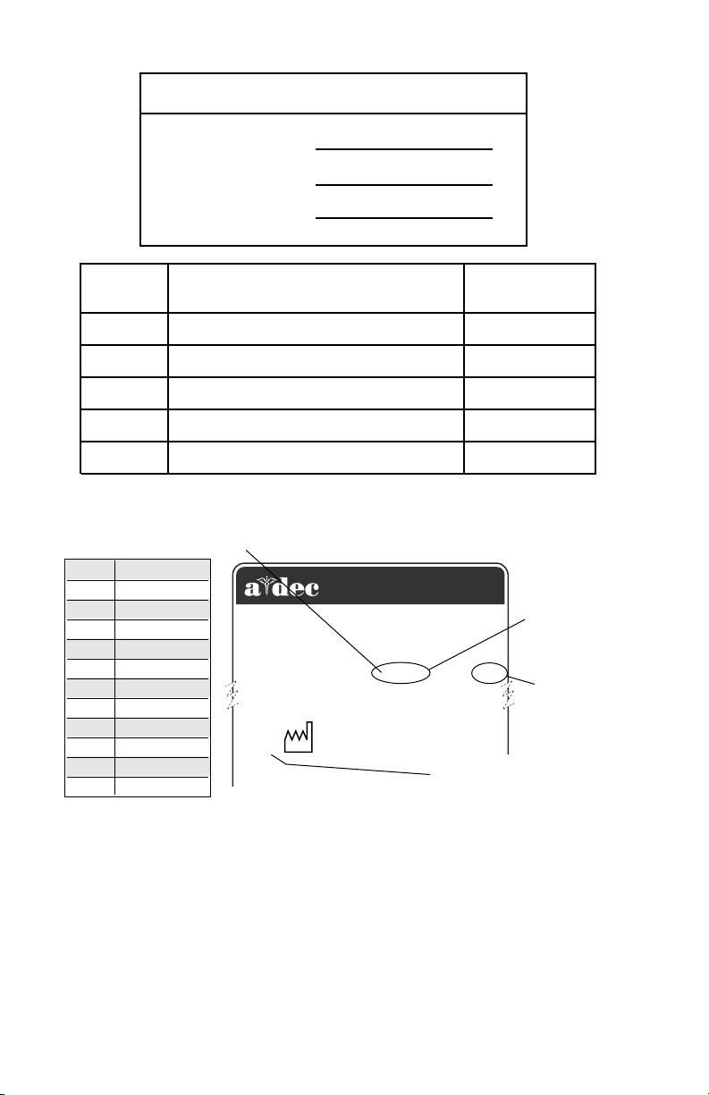
Warranty Information
Serial Number
Model Number
Date Purchased
Date of
Service
ALPHABETICAL EQUIVALENT
TO THE NUMERAL OF THE
MONTH MANUFACTURED
A January
B February
C March
D April
E May
F June
G July
H August
I September
J October
K November
L December
Model/Description of Service
Designated EU Representative: A-dec Dental U.K., Ltd.
Austin House, 11 Liberty Way, Attleborough Fields,
1999
Technician's
2601 CRESTVIEW DRIVE
NEWBERG, OREGON 97132 USA
Nuneaton, Warwickshire, England CV116RZ
Tele: (44) 24 7635 0901
MADE
IN USA
SN: J828287
REF: 2122
YEAR MANUFACTURED
Initials
SERIAL
NUMBER
MODEL
NUMBER
Serial Number Identification
Decade 1011/1021 Chair Serial Number Location:
• Under the seat/toeboard
For service information contact your local authorized A-dec dealer.
Check with local codes and A.D.A. (Americans with Disabilities
Act) Requirements for Installation of this product.
Page 3

A-dec warrants its products and A-dec/W&H Synea
handpieces against defects in material or workmanship for one year from time of delivery. All other
handpiece instrumentation has a warranty period of
six months. A-dec’s sole obligation under the warranty
is to provide parts for the repair, or at its option, to
provide the replacement product (excluding labor). The
buyer shall have no other remedy. (All special,
incidental, and coincidental damages are excluded.)
Written notice of breach of warranty must be given to
A-dec within the warranty period. The warranty does
not cover damage resulting from improper installation
or maintenance, accident or misuse.The warranty does
not cover damage resulting from the use of cleaning,
disinfecting or sterilization chemicals and processes.
The warranty also does not cover light bulbs. Failure to
follow instructions provided in A-dec’s Operation and
Maintenance Instructions (Owner’s Guide) may void
the warranty.
Warranty
NO OTHER WARRANTIES AS TO
MERCHANTABILITY OR OTHERWISE ARE MADE.
All product names used in this document are trademarks or
registered trademarks of their respective holders.
Printed in U.S.A. • Copyright © 2000 • All Rights Reserved
Page 4
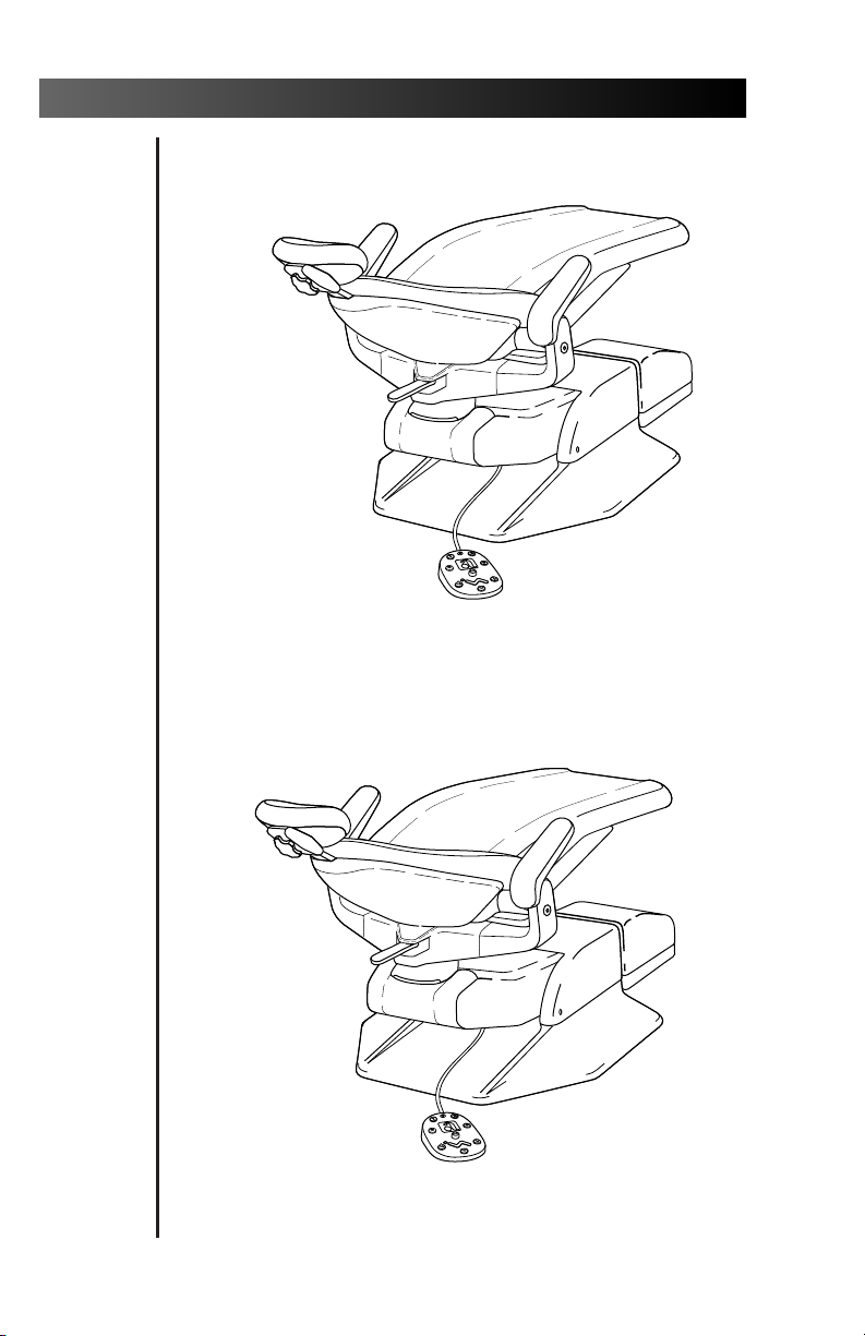
Decade 1011/1021 Chair
Decade 1021 Chair
Decade 1011 Chair
Page 5

Decade 1011/1021 Chair
CONTENTS
Serial number location, service information,
and warranty information are located on the
inside front cover and front page.
About Your Decade Chair ............................... 2
Chair LED .......................................................... 2
Chair Stop Plate ................................................ 2
8-Function Footswitch ..................................... 3
Touch Pad ........................................................ 3
Programming the Chair .....................................5
Folding Armrest .............................................. 7
Swivel Brake .................................................... 8
Double-Articulating Headrest ........................ 9
Positioning For Wheel Chair .................. 10
Headrest Drift Adjustment ..................... 11
Left/Right Conversion ................................... 12
Care Instructions ........................................... 14
Upholstery Replacement .............................. 15
Backrest Upholstery ................................ 15
Seat Upholstery ....................................... 16
Armrest Upholstery ................................. 17
Double-Articulating
Headrest Upholstery ......................... 18
Maintenance ................................................. 19
Adjustments and Specifications ................... 19
Transport the Decade dental unit .................. 20
Identification of Symbols .............................. 21
Classification of Equipment (EN 60601-1) ... 21
1
Page 6
Decade 1011/1021 Chair
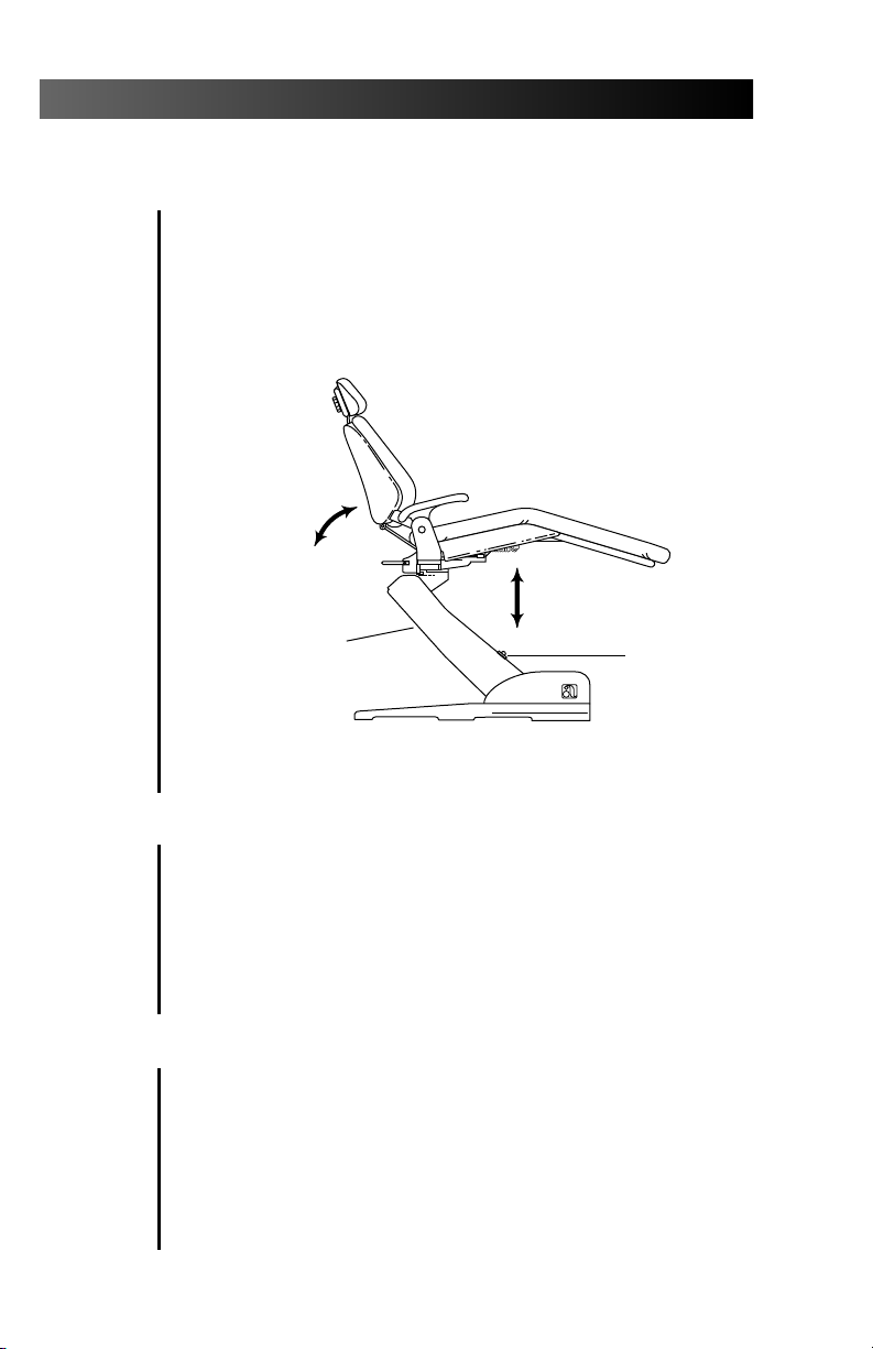
About Your Decade Chair
Your Decade chair is an electronically controlled,
hydraulically powered dental chair.
Chair functions are controlled by the 8-function
footswitch or touch pad (see Figure 2 or 2a on
page 3).
CHAIR BACK /
TOEBOARD TILT
BASE LIFT
CHAIR
STOP
PLATE
Figure 1. Lift, Tilt, and Stop Plate
Chair LED
The chair LED indicates the status of the chair:
ON: Normal operation.
SLOW BLINK: The cuspidor or stop plate limit
switches have been activated. Remove any
obstructing object.
Chair Stop Plate
The chair stop plate (see Figure 1) stops the chair
immediately when any part of it is pressed. Should
anything inadvertently become lodged under the
chair, press Base UP on the footswitch or touch pad
to raise the chair so the object can be removed. As
long as pressure is applied to the stop plate, the
chair base will not go down any further.
LED
2
Page 7
Decade 1011/1021 Chair
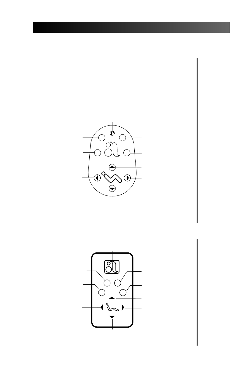
8-Function Footswitch
The 8-function footswitch (see Figure 2) or the
chair touch pad (see Figure 2a) gives you both
manual and programmed control of chair
positioning. The arrows on the footswitch and
touch pad manually control chair back/toeboard
tilt and chair lift. The numbered buttons are for
Entry/ Exit and programmed chair positions.
PROGRAM BUTTON
PROGRAMMABLE
POSITION (1)
PROGRAMMABLE
ENTRY/EXIT (0)
BACK DOWN
Figure 2. 8-Function Footswitch
PROGRAMMABLE
POSITION (1)
PROGRAMMABLE
ENTRY/EXIT (0)
BACK DOWN
1
0
BASE DOWN
PROGRAM BUTTON
0
2
3
21
3
PROGRAMMABLE
POSITION (2)
CUSPIDOR/
RETURN (3)
BASE UP
BACK UP
Touch Pad
PROGRAMMABLE
POSITION (2)
CUSPIDOR/
RETURN (3)
BASE UP
BACK UP
BASE DOWN
Figure 2a. Chair Touch Pad
3
Page 8

Decade 1011/1021 Chair
Manual Control
The Base Up/Down (lift) function controls the
chair’s lift, or vertical movement. To raise the chair,
push the up arrow on the footswitch or touch pad.
To lower the chair, push the down arrow on the
footswitch or touch pad. Push the button until the
chair reaches the desired height, then release it.
The Back Up/Down (tilt) function controls the
chair back/toeboard tilt. To raise the chair back,
push the right arrow on the footswitch or touch
pad. To lower the chair back, push the left arrow
on the footswitch or touch pad. Push the button
until the chair back reaches the desired position,
then release it.
Program Button
The program button (located on the top middle
of the footswitch, or in between the arrows on
the touch pad) is used to save the settings for
Entry/ Exit (0), programmable positions (1 and 2),
and Cuspidor/Return (3).
4
Page 9

Decade 1011/1021 Chair
Programming the Chair
NOTE
When 1 or 2 are pressed on the footswitch or
touch pad, the chair base and back go to the
programmed position.
To stop the chair at any point, press any button
on the footswitch (or press any button on the
touch pad).
Programmable Positions 1 and 2
To send the chair to a programmed operating
position, push either 1 or 2 on the footswitch (press
1 or 2 on the touch pad). Positions 1 and 2 are programmed at the factory to move the chair to the
same position.
To change a programmable position, find the
program button on the footswitch or touch pad
(see Figures 2 or 2a on page 3).
1. Using the manual arrows on the footswitch or
touch pad, set the chair to the operating position
that you prefer.
2. Press and release the program button. An
audible tone will be emitted. Then, within
four seconds, push the button for 1 or 2 to
store that position. You will hear an audible
tone confirming that the programmable
position function has been reprogrammed.
Check the programmed position by manually
3.
moving the chair to another position. Then
push and release the button
Step 2. The chair should move automatically
to the position set in Step 1.
programmed in
5
Page 10

Decade 1011/1021 Chair
Optional Program Functions
Position 3 is
mode. In this
pre-programmed
patient access to the cuspidor. Pressing position
3 a second time lowers the chair back to its
previous operating position.
Position3 may also be used as a third Pre-Position
or as a last position recall.
Contact an authorized A-dec Dealer to have
Position 3 reconfigured to a third Pre-Postion or as
a last position recall.
factory set in the Cuspidor/Return
mode, the chair back will rise to a
upright position provid
ing the
6
Page 11

Decade 1011/1021 Chair
Entry/ Exit (0)
To send the chair to a preset entry/exit position,
push the position 0 button (see Figure 2 or 2a on
page 3).
NOTE
When pushed, Entry/ Exit (0) will cause the
chair base and back to go to the preset
entry/exit position.
To stop the chair at any point, push any button
on the footswitch or touch pad.
If you want to change the preset entry/exit position,
first locate the program button on the footswitch or
touch pad (see Figure 2 or 2a on page 3).
1. Using the manual arrows, set the chair to the
desired patient entry/exit position.
2. Press and release the program button. An audible
tone will be emitted. Within four seconds, press
the Entry/ Exit (0) button on the footswitch or
touch pad. An audible tone will confirm that the
chair has been reprogrammed.
3. Check the Entry/ Exit (0) function by manually
moving the chair to another position. Push the
Entry/ Exit (0) button. The chair will move to the
position you set in Step 1.
Folding Armrest
The armrests fold down and out of the way to
facilitate patient entry/exit. When lifted, the
armrests lock securely in place for patient comfort
during procedures. To lower an armrest, press the
button on the side of the arm. Lock the armrest by
lifting it until it locks in place.
7
Page 12

Decade 1011/1021 Chair
BUTTON
Swivel Brake
LOCK
SWIVEL
BRAKE
LEVER
Figure 4. Folding Armrest
RELEASE
Figure 5. Swivel Brake
When engaged, the chair swivel brake restricts
rotation of the chair. With the brake released, you
can rotate the chair to any position within approx
imately 30° either side of center. To release the
swivel brake, push the brake lever to the right. To
engage the swivel brake, push the brake lever to
the left.
If the chair swivels left or right with the brake
engaged, or if it is difficult to move with the
brake disengaged, the swivel brake tension must
be adjusted.
Using a 3⁄16-inch hex key, adjust the swivel
brake tension. Turn the adjusting screw clockwise
to increase brake friction. Turn the screw counterclockwise to decrease brake friction.
8
Page 13

Decade 1011/1021 Chair
Double-Articulating Headrest
Figure 6. Double-Articulating Headrest
The double-articulating headrest offers the
widest range of headrest positions possible. A
convenient locking knob allows you to easily
accommodate most patients and procedures.
To position the headrest, release the locking
knob by turning the knob out (counterclockwise),
then adjust the headrest as necessary to fit the
head and neck. Lock the headrest in the desired
position by turning the knob in (clockwise).
To move the headrest higher or lower, simply pull
up or push down on the headrest until it is at the
desired height. (Refer to for Headrest Drift Adjustment
on page 12.)
9
Page 14

Decade 1011/1021 Chair
Positioning For Wheel Chair
Figure 7. Positioning For Wheel Chair Usage
The headrest can be used to accommodate
wheelchair patients. Slide the headrest up until it
is free from the chair, turn it 180°, then slide it
back into the backrest and push it all the way
down. Run the chair to its full Back Up position.
Adjust headrest height by moving the chair up or
down (using the Base Up function on the footswitch), then position the headrest as desired.
10
Page 15

Headrest Drift Adjustment
HEADREST
GLIDE BAR
Decade 1011/1021 Chair
Figure 8. Headrest Drift Adjustment
NOTE
The back cover does not have to be removed to
adjust glide bar tension.
If the headrest drifts downward, or if you find the
headrest difficult to move up or down, the glide bar
tension must be adjusted (see Figure 8). Remove the
headrest glide bar to access the adjusting screw.
Using a Phillips screwdriver, adjust the glide bar
tension. Turn the adjusting screw clockwise three
to four revolutions to increase friction and hold the
headrest more securely. Turn the screw counterclockwise three to four revolutions to decrease
friction and allow the headrest to move up and
down more freely. Reinstall the headrest and
recheck glide bar tension.
11
Page 16

Decade 1011/1021 Chair
Left/Right Conversion
When combined with a conversion-compatible
A-dec chair-mounted handpiece control system,
your Decade chair allows you to convert for either
left- or right-hand delivery. If you have a Radius
Delivery System, go to page 15.
1. Raise the chair back, then disconnect the chair
from the power source to prevent injury caused
by accidental lowering of the chair.
2. Remove the chair swivel brake cover.
3. Remove the upholstery pin on both sides
of the chair casting to remove the seat
upholstery (see Figure 9).
®
12
UPHOLSTERY
PIN
REMOVE
SCREWS
Figure 9. Seat Upholstery Removal
4. Place the armrests in their full down position.
5. Move the master on/off toggle to the OFF
position. If the unit is equipped with a selfcontained water system, use the syringe to
bleed the system of air and water pressure,
then remove the bottle.
6. Position the control head over the post box
and the assistant’s arm in front of the chair.
Page 17

Decade 1011/1021 Chair
7. Unscrew and remove the hex-head bolt from
the chair adapter (see Figure 10). Pivot the chair
adapter post and the post box to the other side
of the chair. Align the hole in the chair casting
with the hole in the adapter post.
HEX
BOLT
Figure 10. Left/Right Chair-Mount Conversion
POST
BOX
CHAIR
ADAPTER
8. Reinstall the hex-head bolt in the chair
adapter and tighten it firmly.
9. Position the post box:
NOTE
Avoid rotating the post box in a complete circle.
Doing so will twist the lines inside the floor box.
Cascade Delivery System
Remove the post box covers. Use a 15⁄16-inch
wrench to loosen the bolt located in the center
of the post box frame. Rotate the post box to
the desired position. Then tighten the bolt and
replace the covers.
13
Page 18

Decade 1011/1021 Chair
10. Replace the self-contained water bottle.
11. Plug in the chair, and turn the system on.
Check the post box connections for leakage or
pinched tubing.
12. Return the chair to the entry position and move
the foot control to the other side of the chair.
Radius Delivery System
Simply rotate the handpiece control and light
arms to the desired position.
Care Instructions
The unique Radius bearing mount allows the
delivery system to rotate around the toeboard
in one continuous motion, eliminating the
need for tools or fine adjustments.
For surface cleaning and disinfection instructions,
refer to your Equipment Asepsis Owner’s Guide,
A-dec Publication No. 85.0696.00.
14
Page 19

Decade 1011/1021 Chair
Upholstery Replacement
The upholstery on your chair is installed in four
sections: back, seat, headrest, and armrests. Each
section is easily removed and replaced.
Backrest Upholstery
Remove the four screws securing the backrest
cover and set the cover and screws aside. Using a
5⁄64" hex key, remove the four mounting screws
that hold the upholstery to the backrest, then
remove the existing upholstery. Reverse this procedure to replace the upholstery.
BACKREST
UPHOLSTERY
MOUNTING
SCREWS
BACKREST
UPHOLSTERY
MOUNTING
SCREWS
BACK
FRAME
BACKREST
UPHOLSTERY
Figure 11. Backrest Upholstery
15
Page 20

Decade 1011/1021 Chair
Seat Upholstery
Figure 12. Replacing Seat Upholstery
1. Raise the chair back, then disconnect the chair
from the power source to prevent injury caused
by accidental lowering of the chair.
16
2. Remove the chair swivel brake cover.
3. Remove the existing seat upholstery.
4. Align the new upholstery to the holes in the chair
casting (see Figure 12).
5. Insert the pins through the upholstery and chair
casting (see Figure 12).
6. Reinstall the chair swivel brake cover.
7. Plug in chair.
Page 21

Decade 1011/1021 Chair
Armrest Upholstery
1. Using a 1/8" hex key, first loosen the rearmost mounting screw a 1/2 turn, then
remove the front and middle mounting
screws from the underside of each armrest.
2. Remove the armrest upholstery by sliding it
off the armrest.
3. Install the 3/4" mounting screw and spacer
into the rearmost position on the new armrest
upholstery but do not tighten.
4. Slide the armrest upholstery onto the armrest.
5. Install and tighten all mounting screws (5/8")
into the armrest upholstery.
6. Tighten the rearmost mounting screw.
ARMREST
UPHOLSTERY
MOUNTING
SCREWS (5/8")
SPACER AND
MOUNTING
CHAIR ARMREST
Figure 13. Replacing Armrest Upholstery
SCREW (3/4")
17
Page 22

Decade 1011/1021 Chair
Double-Articulating Headrest Upholstery
Use the following procedure to replace the
double-articulating headrest upholstery.
MOUNTING
SCREWS
(one hidden)
HEADREST
BACK
Figure 14. Replacing Headrest Upholstery
1. Loosen the headrest knob and rotate the headrest
to a full upright position.
TOP MOUNTING
SCREW (hidden)
18
2. Remove the top Phillips mounting screw
located just above the knob assembly.
3. Rotate the headrest back 45° to expose the two
Phillips mounting screws on the headrest back
(see Figure 14). Remove the two screw and the
headrest cushion.
4. To attach the replacement upholstery, reverse
this procedure. DO NOT tighten the screws until
all three screws have been started.
Page 23

Decade 1011/1021 Chair
Maintenance
Upholstery Replacement..................................page 15
Care Instructions .............................................page 14
Equipment Asepsis
Owner’s Guide ....................................85.0696.00
Parts
Maintenance Parts
Owner’s Guide .....................................85.2634.00
Adjustments and Specifications
Programming the Chair ....................................page 5
Swivel Brake.......................................................page 8
Headrest Drift Adjustment...............................page 11
Left/Right Conversion......................................page 12
Chair Capacity:
Patient Load: 300 lbs. (135 kg) maximum.
Accessory Load: 150 lbs. (67.5 kg) maximum.
Maximum Load from Accessories:
Chair Adapter: 200 lbs. (90 kg) weight combined
with a moment of 250 ft. lbs. (339 N·m)
Radius Front Mount: 180 lbs. (81 kg)
weight combined with a moment of
525 ft. lbs. (711.8 N·m)
Radius Rear Mount: 70 lbs. (31.5 kg)
weight combined with a moment of
160 ft. lbs. (216.9 N·m)
Specifications are subject to change without notice.
19
Page 24

Decade 1011/1021 Chair
Safety Considerations for
Accessory Equipment
The use of accessory equipment not complying with
the equivalent safety requirements of this equipment
may lead to a reduced level of safety of the resulting
system.
Consideration relating to the use of accessory equipment shall include:
Evidence that Safety Certification of the accessory
equipment has been performed in accordance to the
appropriate IEC 601 and IEC 601-1 Harmonized
National Standards.
Transporting the Decade Unit
When transporting the dental unit the chair base
should be fully down, and the chair back should be
fully up. The chair body should be secured to the
chair baseplate. Do not lift the chair by the chair
body.
20
The delivery system should be over the seat
upholstery and the light should be centered above
the chair.
The delivery system and light should be secured to
prevent movement. The entire Dental Unit should be
secured to the transporting vehicle.
Page 25

¤
Decade 1011/1021 Chair
Identification of Symbols
Recognized by Underwriters Laboratories Inc. ® with respect to
electric shock, fire and mechanical hazards only in accordance
with UL 2601-1. Recognized with respect to electric shock, fire,
mechanical and other specified hazards only in accordance with
CAN/CSA C22.2, No. 601.1.
UL listed to US (UL 544) and Canadian (CAN/CSA C22.2, No.
125) safety standards.
LISTED
Classified by Underwriters Laboratories Inc. ® with respect to
electric shock, fire and mechanical hazards only in accordance
with UL 2601-1. Classified with respect to electric shock, fire,
mechanical and other specified hazards only in accordance with
CAN/CSA C22.2, No. 601.1.
Conforms to European Directives
Protective earth (ground).
Functional earth (ground).
Attention, consult accompanying documents.
!
TYPE B APPLIED PART.
CLASS II EQUIPMENT.
(refer to Declaration Statement)
Classification of Equipment (EN 60601-1)
Type of shock protection:
CLASS I EQUIPMENT
(Dental Chairs, Dental Lights, & Power Supplies)
CLASS II EQUIPMENT
(Chair, Wall, & Cart Mounted Delivery Systems)
Degree of shock protection:
TYPE B APPLIED PART (All products)
Degree of protection against water ingress:
ORDINARY EQUIPMENT (All products)
Mode of operation
CONTINUOUS OPERATION
(All models except Dental Chairs)
Mode of operation
CONTINUOUS OPERATION
WITH INTERMITTENT LOADING (Dental Chairs)
21
Page 26

Decade 1011/1021 Chair
Notes
22
Page 27

2601 Crestview Drive
Newberg, Oregon 97132 U.S.A.
Telephone 1-800-547-1883
(503) 538-7478
Fax (503) 538-0276
Designated Representative’s Address:
A-dec Dental U.K., Ltd.
Austin House
11 Liberty Way
Attleborough Fields Industrial Estate,
Nuneaton, Warwickshire,
England CV11 6RZ
Telephone: 0800-ADECUK (233285) Within UK
00 44 24 7635 0901 Outside UK
Fax: 00 44 24 7634 5106
Designated Representative’s Address:
A-dec Australia
41-43 Bowden Street
Alexandria, N.S.W. 2015, Australia
Telephone: (61) 1.800.225010 within Australia
00612-9699-4600 outside Australia
Fax: 00612-9699-4700
85.2635.00
2000-03 Rev C
(1968.07)
Made with 50% waste paper
Printed in USA.
Copyright © 2000,
All Rights Reserved.
 Loading...