

Page 1

Owner's Guide
CASCADE
®
POST B
OX
85.2615.00
Page 2
N/A
N/A
For service information contact your local authorized A-dec dealer.
Check with local codes and A.D.A. (Americans with Disabilities Act)
requirements for installation of this product.
Page 3
A-dec warrants its products and A-dec/W&H Synea
handpieces against defects in material or workmanship
for one year from time of delivery. All other handpiece
instrumentation has a warranty period of six months.
A-dec’s sole obligation under the warranty is to provide
parts for the repair, or at its option, to provide the
replacement product (excluding labor). The buyer shall
have no other remedy. (All special, incidental, and
coincidental damages are excluded.) Written notice of
breach of warranty must be given to A-dec within the
warranty period. The warranty does not cover damage
resulting from improper installation or maintenance,
accident or misuse.The warranty does not cover damage resulting from the use of cleaning, disinfecting or
sterilization chemicals and processes. The warranty also
does not cover light bulbs. Failure to follow instructions
provided in A-dec’s Operation and Maintenance
Instructions (Owner’s Guide) may void the warranty.
Warranty
NO OTHER WARRANTIES AS TO
MERCHANTABILITY OR OTHERWISE ARE MADE.
All product names used in this document are trademarks or
registered trademarks of their respective holders.
Printed in U.S.A. • Copyright © 1999 • All Rights Reserved
Page 4
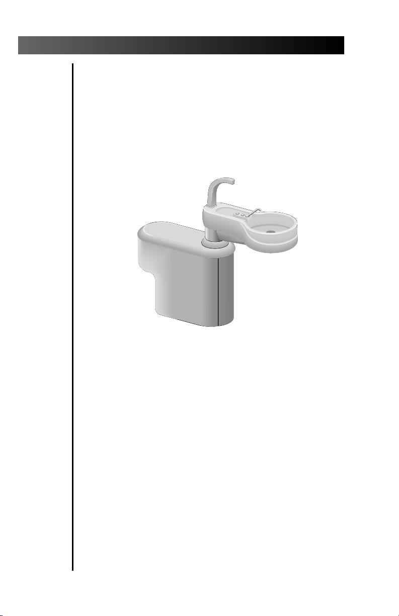
Cascade Post Box
Cascade Post Box
(with optional Cuspidor)
Page 5

Cascade Post Box
CONTENTS
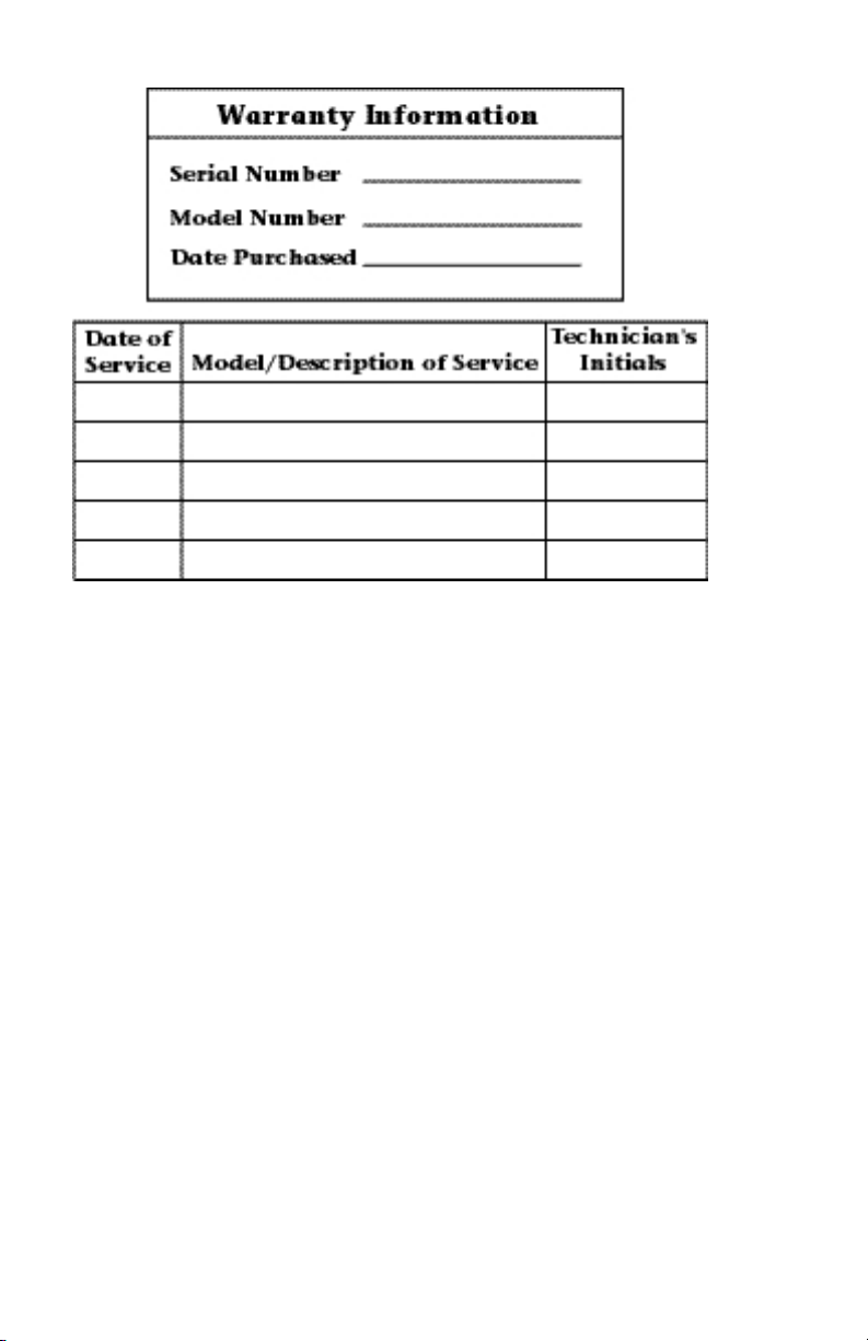
Service information and warranty information
are located on the inside front cover and
front page.
About Your Cascade Post Box .......................... 2
Removing Side Covers ................................ 3
Air/Water Connections .................................... 4
Inline Tubing Connections ........................ 5
Bowl Rinse and Cup Fill Water
Flow Adjustment Controls ..................... 6
Electrical ........................................................... 7
Leveling Adjustment ........................................ 8
Side Cover Adjustment ................................... 10
Care Instructions ............................................ 11
Maintenance ................................................. 12
Adjustments and Specifications ................... 12
Identification of Symbols .............................. 13
Classification of Equipment (EN 60601-1) ... 13
1
Page 6
Cascade Post Box
275
136
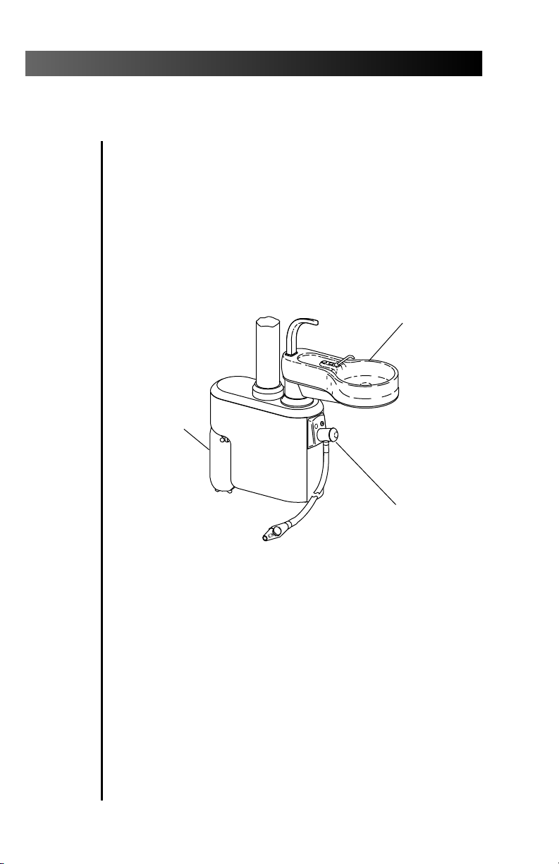
About Your Cascade Post Box
The Cascade Post Box (see Figure 1) contains utility
connections between the floor box and other A-dec
products such as the control head, foot control, light,
cuspidor, or assistant's instrumentation. The leveling
mechanism is also housed within the post box.
Depending on the options chosen, the post box may
also contain a solids separator, a recessed location for
a self-contained water system and quick disconnect
(QD) outlets for the hydrocolloid, air, or scaler.
SELFCONTAINED
WATER
SYSTEM
(Optional)
CUSPIDOR
(Optional)
SOLIDS
C
°
6
°F
3
5
1
7
2
COLLECTOR
(Optional)
Figure 1. Post Box
The post box is made from materials which resist
chipping, stains and chemicals commonly used in
the operatory.
Enclosed on the air and water side of the post box
are the inline tubing connections for air and water
supply lines (see Figure 4 on page 5). If your unit
has the optional cuspidor, you will find the flow
adjustment controls for the cuspidor bowl rinse
and cup fill on this side.
2
Page 7
Cascade Post Box
275
136
The electrical side of the post box (see Figure 6 on
page 7) contains a variety of electrical connections.
The type and number of connections depend on the
options you have selected. Connections may
include those from the floor box to a dental light,
the cuspidor safety switch, an intra-oral light source
handpiece, a low voltage water heater/heated
syringe tubing, a curing light, or a scaler. If your
unit has the touch control, the connection from the
chair to the touch control on the control head will
be located on this side.
Some international units have a larger size post
box to enclose a dry vacuum separator.
Removing Side Covers
SIDE COVERS
°C
6
°F
3
5
1
7
2
Figure 2. Removing Side Covers
To remove a side cover, insert your fingers under
the lower edge of the cover and pull out and down
on the cover (see Figure 2).
To replace the cover, insert the upper edge of the
cover into the groove, align the studs on the inside
of the cover with the spring clips on the post box
and snap the cover into place.
3
Page 8

Cascade Post Box
Air/Water Connections
Air and water connections (see Figure 3) are
located on one side of the post box. On a right-hand
delivery system, these air and water connections
will be on the left.
TYPICAL AIR
OR WATER
CONNECTIONS
Figure 3. Air/Water Connections
4
Page 9

Cascade Post Box
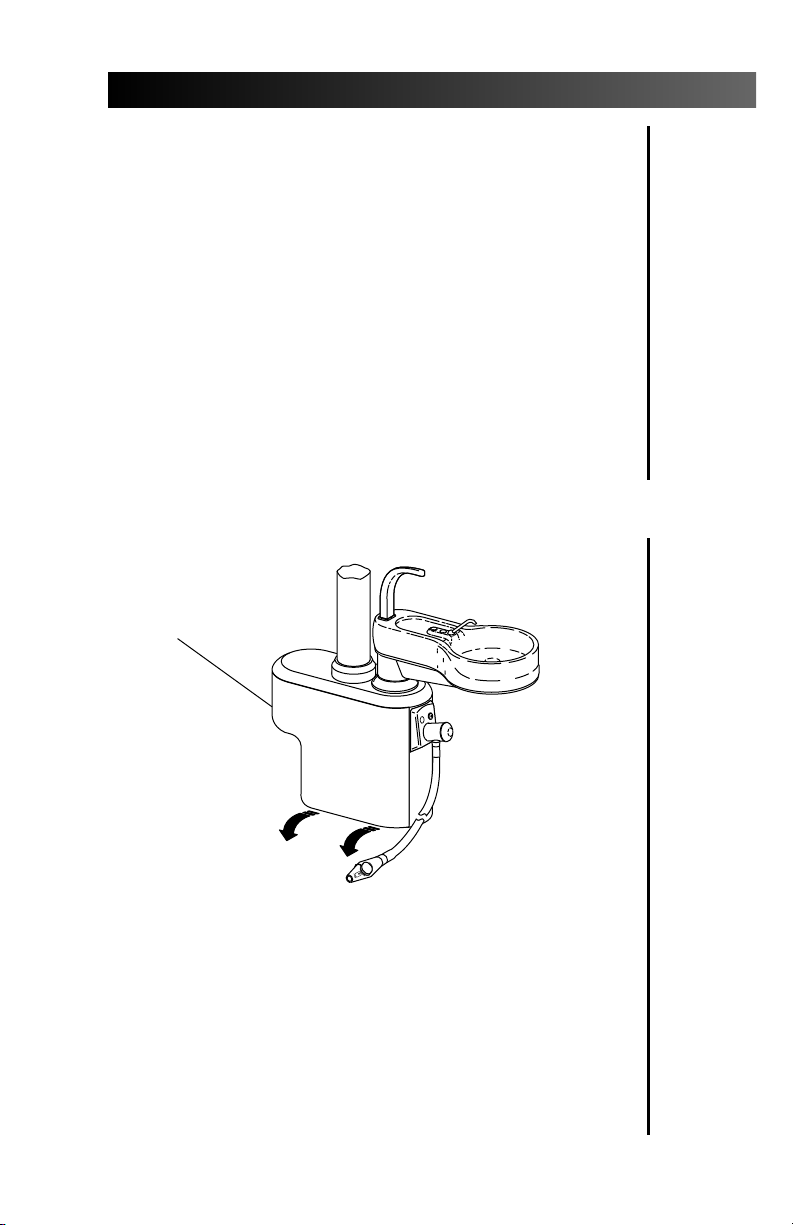
Inline Tubing Connections
Tubing from the floor box is channeled through
the umbilical to the post box where this tubing is
attached using inline connectors to the tubing
coming from the control head, foot control, cuspidor,
or assistant’s instrumentation.
Figure 4. Inline Connections
5
Page 10

Cascade Post Box
Bowl Rinse and Cup Fill Water Flow Adjustment Controls
If you have chosen the cuspidor option, the
controls to adjust the flow of water to the bowl
rinse and cup fill will be located on the air/water
side of your post box (see Figure 5). Complete
instructions for making water flow adjustments
are included in Cascade 7284 and Radius
Cuspidor Owner’s guide, A-dec Publication No.
85.2609.00.
®
7285
Figure 5. Flow Adjustment Controls
6
Page 11
Cascade Post Box
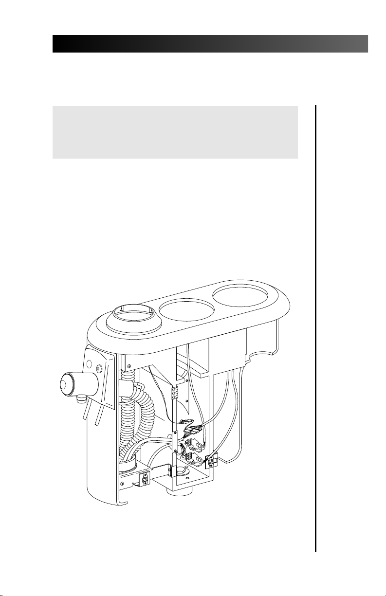
Warning
Only an authorized A-dec dealer should service, make
repairs or adjustments to electrical components on
this side of the post box.
The electrical side of the post box (see Figure 6)
contains a variety of electrical connections.
Depending on the options selected, the electrical
connections may include those from the chair to
the touch control on the control head or from the
floor box to the dental light, intra-oral light source,
low voltage water heater/heated syringe tubing,
curing light, scaler, or cuspidor safety switch.
Electrical
Figure 6. Electrical Side of Housing
7
Page 12

Cascade Post Box
Leveling Adjustment
Your post box should be leveled during installation.
However, if adjustment becomes necessary, remove
the side cover (refer to page 3). Then proceed as follows:
1. Using a 15⁄16-inch open end or socket
wrench, loosen the center bolt (see Figure 7)
approximately three turns so the post box
will wobble.
2. Place a magnetic bubble level on the post.
Move the level so that you check the level
parallel and perpendicular to the chair.
Figure 7. Leveling Mechanism
8
Page 13

SPRING
WASHER
Cascade Post Box
ADJUSTMENT
SET SCREWS
CENTER
BOLT
THRUST
WASHER
Figure 8. Leveling Adjustment
3. Using a 3⁄16-inch hex key, adjust the three
setscrews (see Figure 8) until the unit is level.
Make sure the setscrews are adjusted so all
three contact the thrust washer located
between the bottom of the post box and the
unit mount.
4. Tighten the center bolt so it is snug and the
spring washer (see Figure 8) is flattened. When
properly adjusted, the post box will be level
and will not wobble.
9
Page 14

Cascade Post Box
Side Cover Adjustment
The side covers on your post box should be
adjusted at the time of installation. If the covers
become too loose or too tight, you may adjust
them. To make the adjustment, remove the side
cover (refer to page 3) and locate the adjustment
brackets (see Figure 9).
10
Figure 9. Side Cover Adjustment
Visually determine how much of an adjustment
is needed. Use a 1⁄8-inch hex key to loosen the
screws on the side adjustment (see Figure 9), slide
the bracket to the proper position and retighten
the screw.
Use a Phillips screw driver to loosen the screws on
the bottom of the front bracket (see Figure 9), slide
the bracket to the proper position and retighten
the screws.
Page 15

Cascade Post Box
Care Instructions
For recommended asepsis instructions,
refer to Equipment Asepsis (A-dec Publication
No. 85.0696.00).
11
Page 16

Cascade Post Box
Maintenance
Care Instructions
Equipment Asepsis
Owner’s Guide ....................................85.0696.00
Parts
Maintenance Parts
Owner’s Guide .....................................85.2634.00
Power Supplies
Floor Boxes
Owner’s Guide .....................................85.2611.00
Adjustments and Specifications
Water Flow Adjustments (for optional cuspidor)
Cascade 7284 and Radius 7285 Cuspidor
Owner’s Guide ....................................85.2609.00
Leveling Adjustment..........................................page 8
Side Cover Adjustment ....................................page 10
12
Minimum air, water and vacuum service
requirements for proper unit operation:
Air: 2.50 cfm (70.80 l/min) at 80 psi (551 kPa).
Water: 1.50 gpm (5.68 l/min) at 40 psi (276 kPa).
Vacuum: 12 cfm (339.84 l/min) at 8 inches of
mercury (27 kPa).
If mounting a non-A-dec light, nominal acceptable
weight is 12 lbs (5.44 kg).
Maximum unit weight: 160 lbs (72.58 kg).
Maximum moment at the unit mount arm created
by the freestanding unit is 250 ft-lbs (339 N·m)
along the axis of the post box.
Specifications are subject to change without notice.
Page 17
¤
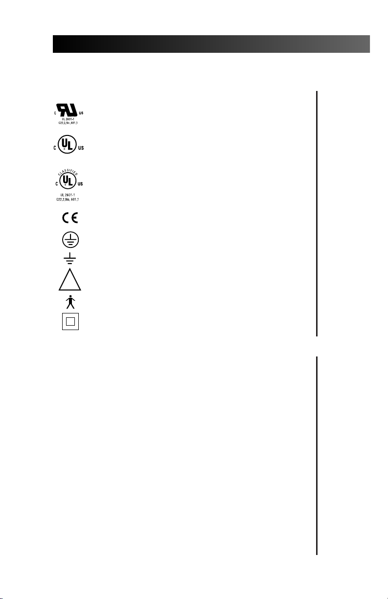
Identification of Symbols
Recognized by Underwriters Laboratories Inc. ® with respect to
electric shock, fire and mechanical hazards only in accordance
with UL 2601-1. Recognized with respect to electric shock, fire,
mechanical and other specified hazards only in accordance with
CAN/CSA C22.2, No. 601.1.
UL listed to US (UL 544) and Canadian (CAN/CSA C22.2, No.
LISTED
125) safety standards.
Classified by Underwriters Laboratories Inc. ® with respect to
electric shock, fire and mechanical hazards only in accordance
with UL 2601-1. Classified with respect to electric shock, fire,
mechanical and other specified hazards only in accordance with
CAN/CSA C22.2, No. 601.1.
Cascade Post Box
Conforms to European Directives
Protective earth (ground).
Functional earth (ground).
Attention, consult accompanying documents.
!
TYPE B APPLIED PART.
CLASS II EQUIPMENT.
(refer to Declaration Statement)
Classification of Equipment (EN 60601-1)
Type of shock protection:
CLASS I EQUIPMENT
(Dental Chairs, Dental Lights, & Power Supplies)
CLASS II EQUIPMENT
(Chair, Wall, & Cart Mounted Delivery Systems)
Degree of shock protection:
TYPE B APPLIED PART (All products)
Degree of protection against water ingress:
ORDINARY EQUIPMENT (All products)
Mode of operation
CONTINUOUS OPERATION
(All models except Dental Chairs)
Mode of operation
CONTINUOUS OPERATION
WITH INTERMITTENT LOADING (Dental Chairs)
13
Page 18

Cascade Post Box
Notes
14
Page 19

2601 Crestview Drive
Newberg, Oregon 97132 U.S.A.
Telephone 1-800-547-1883
(503) 538-7478
Fax (503) 538-0276
Designated Representative’s Address:
A-dec Dental U.K., Ltd.
Austin House
11 Liberty Way
Attleborough Fields Industrial Estate,
Nuneaton, Warwickshire,
England CV11 6RZ
Telephone: 0800-ADECUK (233285) Within UK
00 44 24 7635 0901 Outside UK
Fax: 00 44 24 7634 5106
Designated Representative’s Address:
A-dec Australia
41-43 Bowden Street
Alexandria, N.S.W. 2015, Australia
Telephone: (61) 1.800.225010 within Australia
00612-9699-4600 outside Australia
Fax: 00612-9699-4700
85.2615.00
1999-09 Rev G
(01781)
Made with 50% waste paper
Printed in USA.
Copyright © 1999,
All Rights Reserved.
 Loading...