

Page 1

85.0812.00, 2003 CM-1
Cascade Master Series Overview
The Cascade Master Series option consists of five components, which control standard chair
and delivery system functions. These components include: master touchpad, master 17-watt
power supply, master circuit board, solenoid valve manifolds, and master dental light air-electric
switches. This section presents details on how to service the components and troubleshoot
specific problems.
Page 2
85.0812.00, 2003 CM-2
Cascade Master Series Components
Identifying the
Components
Master Touchpads
Master 17-Watt Power
Supply
Master Circuit Board
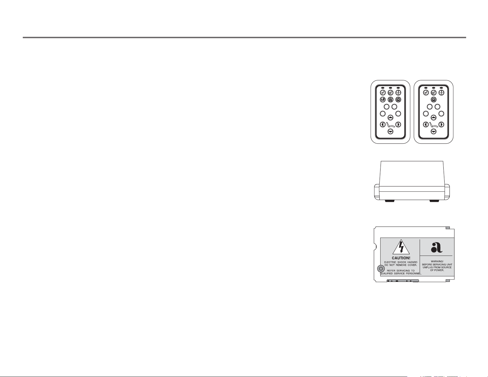
This overview provides a brief description of each of the five
master series components.
The master touchpad controls low voltage electrical signals that
activate chair functions in the same manner as the standard chair
touchpad. It also sends low voltage electrical signals to a bank of
solenoid valves, which control the air pilot signals used to
activate various delivery system functions, the dental light, and,
optionally cuspidor functions.
The master 17-watt power supply connects directly to the power
mains and provides power to the master circuit board.
The master circuit board receives electrical signals from the
master touchpad to activate or deactivate a desired function. It
then sends a low voltage electronic signal to the appropriate
solenoid valve, opening or closing it to control air flow to the
balance of the delivery system.
Master Touchpads
Master 17-Watt
Power Supply
Master Circuit Boards
1 2
0
3 0
2
1
3
Page 3
85.0812.00, 2003 CM-3
Cascade Master Series Components
Solenoid Valve Manifolds
Master Dental Light Air
Electric Switches
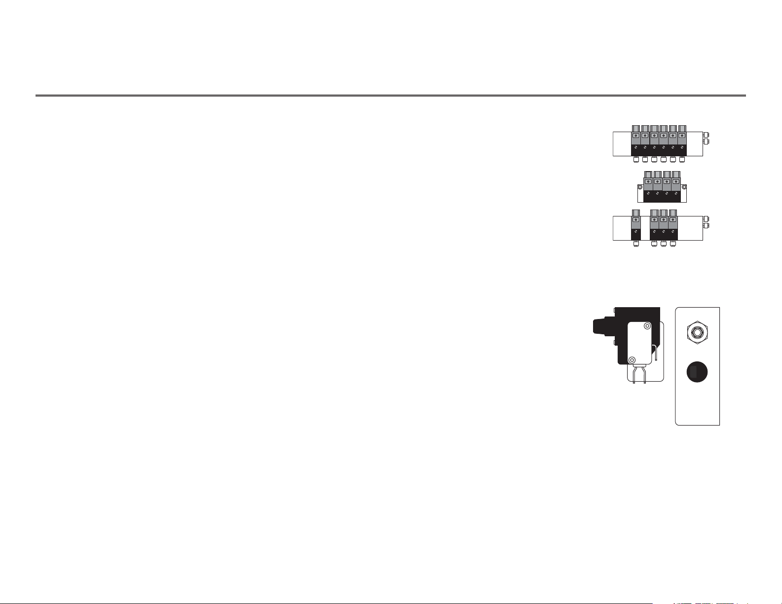
The solenoid valve manifolds can contain a maximum of six
normally closed solenoids, which control the pilot air signals used
to activate standard Cascade unit and cuspidor functions. Each
solenoid valve receives an electrical signal from the master circuit
board, which causes it to open (no signal causes the solenoid to
close). Each of the solenoid valves have an indicator that lights
when the valve receives an electrical signal from the master circuit
board. This signal causes the valve to open or close thereby
controlling the flow of the pilot air signal through the valve.
The master dental light air-electric switch is connected in the
common return for the light. It receives a pilot air signal from the
solenoid valve manifold. This signal closes the normally open
switch, which completes the electrical circuit, allowing the dental
lamp to light.
Solenoid Valve Manifolds
Master Dental Light Air-
Electric Switches
Page 4
85.0812.00, 2003 CM-4
Cascade Master Series Master Touchpad
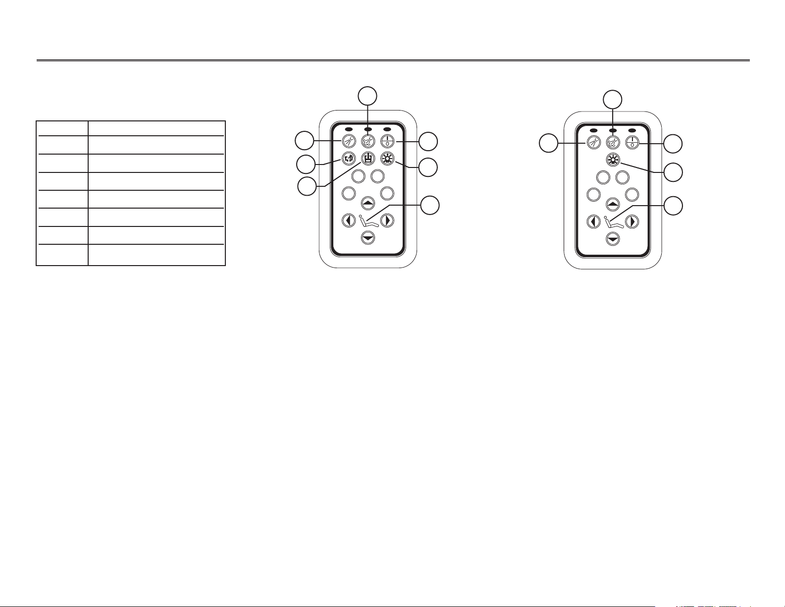
Master Touchpad with
Cuspidor Functions
Master Touchpad without
Cuspidor Functions
Master Touchpad
Item # Description
1 Coolant air On/Off
2 Coolant water On/Off
3Master On/Off
4 Cuspidor bowl rinse
5 Cuspidor cup fill
6 Dental light On/Off
7Program button
1
2
2
1
3
3
4
5
6
6
7
7
0
1 2
3
1 2
0
3
Page 5
85.0812.00, 2003 CM-5
Cascade Master Series Master Touchpad Functions
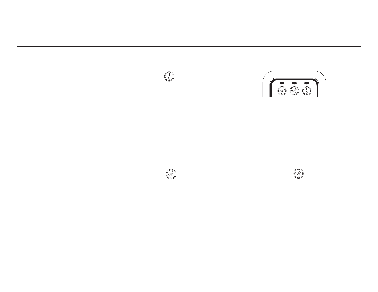
Air, water and electrical power to the
handpiece control system, and dental
light are turned ON or OFF when this
button is pressed. An electrical signal is
sent from the touchpad to the circuit
board, which opens the master air
solenoid valve, allowing the pilot air to
activate the system.
Water coolant to the handpieces is turned
ON or OFF when this button is pressed. An
electrical signal is sent from the touchpad
to the circuit board, which opens the water
coolant signal solenoid, allowing the water
coolant signal air to flow to the handpiece
control block. This opens the water valve
when the foot control is pressed. Handpiece
coolant water can then be adjusted in the
normal manner.
When the master On/Off, Air Coolant
On/Off, and Water Coolant On/Off
buttons are pressed, the indicator above
the individual function switch (on the
master touchpad) illuminates to indicate
the function is ON.
Air coolant to the handpieces is turned
ON or OFF when the button is pressed. An
electrical signal is sent from the touchpad
to the circuit board which, opens the air
coolant signal solenoid, allowing the air
coolant to flow to the handpiece control
block. Handpiece air coolant can then be
adjusted. Refer to Handpiece Controls (HC)
for adjustment instructions.
Master On/Off
Coolant Air On/Off
Indicators
Coolant Water On/Off
Using the Master
Touchpad
Page 6

85.0812.00, 2003 CM-6
Cascade Master Series Master Touchpad Functions
The Cascade master touchpad chair
controls are identical to the standard A-dec
chair touchpad. Refer to the Chairs (CH)
section for chair programming instructions.
The cuspidor cup fill function may be
accomplished by pressing the manual
button on the top of the cuspidor or by
pressing the touchpad button. An electrical
signal is sent from the touchpad to the
circuit board, which opens the cup fill
signal valve, allowing the pilot air signal to
flow to the cup fill circuit in the cuspidor.
Cup fill functions may then be adjusted.
Refer to Post Boxes & Cuspidors (PB) for
adjustment instructions.
The cuspidor bowl rinse function may be
accomplished by pressing the manual
button on the top of the cuspidor or by
pressing the touchpad button. An electrical
signal is sent from the touchpad to the
circuit board, which opens the bowl rinse
signal valve, allowing the pilot air signal
to flow to the bowl rinse circuit in the
cuspidor. Bowl rinse functions may then be
adjusted in the normal manner.
Dental Light On/Off
Cuspidor Bowl Rinse
Cuspidor Cup Fill
Chair Controls
The dental light is turned ON or OFF when
this button is pressed. An electrical signal is
sent from the touchpad to the circuit board,
which opens the dental light solenoid. Air
from the solenoid closes the dental light
air-electric switch, turning the light ON.
Light intensity and other adjustments are the
same as A-dec dental lights. Refer to Dental
Lights (LI) for adjustment instructions.
1 2
0
3
Page 7

85.0812.00, 2003 CM-7
Cascade Master Series Cascade Delivery System Flow Diagram
Refer to Handpiece
Controls (HC) for details
Cascade Master Series touchpad
(with cuspidor functions)
Control head
Refer to Dental Lights (LI) for details
Master dental light air actuated switch
Master
circuit
board
Dental light
Shuttle valves
Cuspidor
Refer to Post Boxes &
Cuspidors (PB) for details
Refer to Floor Boxes &
Power Supplies (FB) for details
Refer to Foot Controls (FC)
for details
Post box
Foot control
Air signal valve manifold
To 24 VAC, 17-watt power
supply, and chair circuit board
From 300-watt
power supply
Power mains
Floor box
17-watt master
power supply
After November 1999
VOLTS AC
00617 24 24 24 24
1 2
0
3
CAUTION!
WARNING!
ELECTRIC SHOCK HAZARD
BEFORE SERVICING UNIT
DO NOT REMOVE COVER.
UNPLUG FROM SOURCE
OF POWER.
REFER SERVICING TO
QUALIFIED SERVICE PERSONNEL.
BLK
RED
WAMA L B C
CONTROL
CHAIR
34
50
40
60
5
2
30
70
20
80
1
6
90
10
100
0
psi
2
7
0
kg/cm
MA
0 1
B L W A C
0 1
0 1 0 1 0 1
0 1
34
50
40
60
5
2
30
70
20
80
1
6
90
10
100
0
psi
2
7
0
kg/cm
Page 8

85.0812.00, 2003 CM-8
Cascade Master Series Cascade Delivery System Flow Diagram
Refer to Handpiece
Controls (HC) for details
Cascade master Series touchpad
(with cuspidor functions)
Control head
Refer to Dental Lights (LI) for details
Master dental light air actuated switch
Master
circuit
board
Dental light
Shuttle valves
Cuspidor
Refer to Post Boxes &
Cuspidors (PB) for details
Refer to Floor Boxes &
Power Supplies (FB) for details
Refer to Foot Controls
(FC) for details
Post box
Foot control
Air signal valve manifold
To chair circuit board
To 300-watt
power supply
Power mains
Floor box
17-watt master power supply
Before November 1999
2
1
20
34
40
30
10
0
0
12345678
1 2
0
3
50
60
5
70
80
6
90
100
psi
2
7
kg/cm
MA
B L W A C
0 1
0 1
0 1 0 1 0 1
CAUTION!
WARNING!
ELECTRIC SHOCK HAZARD
BEFORE SERVICING UNIT
DO NOT REMOVE COVER.
UNPLUG FROM SOURCE
OF POWER.
REFER SERVICING TO
QUALIFIED SERVICE PERSONNEL.
BLK
RED
WAMA L B C
CONTROL
CHAIR
0 1
34
50
40
60
5
2
30
70
20
80
1
6
90
10
100
0
psi
2
7
0
kg/cm
Page 9

CHAIR
BLK
RED
WARNING!
MA
To floor box
To foot control
To control head
85.0812.00, 2003 CM-9
Cascade Master Series Radius Delivery System Flow Diagram
1
3
2
Chair-Mount Adapter
Item # Part # Description
1 75.0957.00 Master circuit board
2 044.170.00 Radius master dental light
air-actuated switch
3 046.147.00 Solenoid
From foot control
To circuit board
To
dental
light
MA
LA C
0 10 10 10 1
CAUTION!
ELECTRIC SHOCK HAZARD
DO NOT REMOVE COVER.
REFER SERVICING TO
QUALIFIED SERVICE PERSONNEL.
BLK
RED
WAMAMAL B C
WARNING!
BEFORE SERVICING UNIT
UNPLUG FROM SOURCE
OF POWER.
CONTROL
CHAIR
Page 10

85.0812.00, 2003 CM-10
Cascade Master Series Solenoid
Installing a Solenoid
The solenoid valves control the air pilot signals that activate standard Cascade unit and cuspidor
functions. The following steps will guide you through the procedure for installing a solenoid.
Removing a Solenoid
Replacing a Solenoid
Task Description
To remove a solenoid:
1Turn OFF the unit.
2Press down on the wire connector lever and gently
pull the connector out of the solenoid.
3 Remove the two screws which secure the
solenoid to the manifold.
4Remove the solenoid from the manifold.
To replace a solenoid:
1 Install the new solenoid on the manifold.
2 Screw in the two screws to secure the solenoid.
3 Replace the wire connector to the solenoid.
Screws
Solenoid
046.147.00
Wire connector lever
Manifold
Removing or Replacing a Solenoid
Page 11

85.0812.00, 2003
CM-11
Cascade Master Series Service
Servicing the Unit
Opening a Solenoid
Before servicing the unit:
• Ensure that a minimum of 60 psi of air is being supplied to the unit. The indicators on
the individual solenoid valves will light when air pressure is above 30 psi. The unit will
not function unless the air pressure is above 60 psi.
• Ensure that the unit is ON. The indicator above the button should be illuminated when
the unit is ON. If the indicator is not illuminated, press the master On/Off button.
To manually open a solenoid, carefully turn the solenoid valve's manual override
selector (orange) a quarter turn clockwise, to the ON (1) position. Do not force the override
On/Off selector beyond the ON (1) position.
When a solenoid is manually opened, the indicator will not illuminate. The function will remain ON
until the unit is turned OFF or the manual override selector has been returned to the OFF (0) position.
CAUTION
Use minimal force when manually opening a
solenoid. Excessive force, or turning the
override selector too far, will permanently
damage the solenoid.
Indicator
Manual override
0
1
0
1
0
1
0
1
0
1
0
1
Page 12

85.0812.00, 2003 CM-12
Cascade Master Series Troubleshooting
Tips and troubleshooting information are listed in the following charts to assist in diagnosing
Cascade Master Series problems. The charts are not intended to cover every situation, but include
the most common problems you may encounter.
Troubleshooting
Cascade Master Series
Problem
Action
The Master On/Off, coolant air,
or coolant water touchpad
function do not work
Cup fill and bowl rinse functions
do not work from the touchpad
Manually open the function’s solenoid. Refer to Opening a Solenoid.
Activate the cup fill and bowl rinse functions by pressing the control buttons on the top of the
cuspidor. Refer to Post Boxes and Cuspidors.
If . . . Then . . .
Function doesn't work when the
solenoid valve is manually opened
Function operates properly when the
solenoid valve is overridden
Refer to the specific function in
this section.
If . . .
Then . . .
Control buttons on top of the cuspidor
do not work
Control buttons on top of the cuspidor
do work
Refer to Post Boxes & Cuspidors (PB) for
troubleshooting information.
Refer to specific function in this section.
CAUTION
Do not override the cup fill or bowl rinse solenoids. This
will cause water to continually flow at the cuspidor.
Refer to Handpiece Controls (HC) for
troubleshooting information.
Page 13

85.0812.00, 2003
Cascade Master Series Troubleshooting
Problem
Action
Dental light On/Off touchpad
functions do not work
Follow these steps to determine the problem with the touchpad functions.
Task Description
1Disconnect the dental light from its power supply.
2Disconnect the two black wires from the master dental light air-actuated switch, and connect the
wire from the wiring connector to the black wire going to the light.
3Re-connect the dental light to its power source.
If . . .
Then . . .
Light does not illuminate
Light does illuminate
Refer to Dental Lights (LI) for
troubleshooting information.
Refer to the Touchpad
Troubleshooting section.
To dental light
Master dental light
air-actuated switch
From dental
light solenoid
CM-13
Page 14

85.0812.00, 2003 CM-14
Cascade Master Series Troubleshooting
Problem
Action
Chair touchpad functions
do not work
Unit does not work when the
master On/Off control is pressed
The Cascade Master Series touchpad chair functions are identical to the standard chair touchpad
functions. Refer to Chairs (CH) for troubleshooting information.
Check the Master circuit board. The LED should be ON.
If the LED is OFF:
Check the mains input voltage to the 17-watt power supply:
• 120 VAC should be +10% 50-60 Hz, .14 Amps
• 230 VAC should be +10% 50-60 Hz, .07 Amps
Check the 17-watt power supply output voltage:
• It should be 22 VAC, 65 Amps.
If . . .
Then . . .
Main input voltage does not meet
the above specification or is absent
Main input voltage does meet the
above specification
Contact a local electrical contractor to
correct the power condition.
Check the 17-watt power supply
output voltage.
If . . .
Then . . .
Power supply output is 22 VAC
Master 17-watt power supply output
is not 22 VAC
Master circuit board has malfunctioned
and must be replaced.
17-watt power supply must be replaced.
Page 15

85.0812.00, 2003 CM-15
Cascade Master Series Troubleshooting
Problem
Action
Unit does not work when the
master On/Off control is pressed
Master dental light does not
illuminate when the solenoid
valve is manually opened
If LED is ON:
Check air pressure being supplied to the unit. It should be 60 psi (minimum) at the floor box utilities.
Check to see if the Master circuit board and the 17-watt power supply both function.
Check the indicator on the Master dental light solenoid valve.
If . . .
Then . . .
Air pressure meets specifications,
and the selected function operates
when solenoid is opened manually
Air pressure does not meet the
above specification
Replace the solenoid. Refer to Replacing
a Solenoid.
Refer to Floor Boxes & Power Supplies
(FB) for utility information.
If . . .
Then . . .
Indicator lights when the function is
activated at the touchpad
Indicator does not light when the
dental light button is pressed on
the touchpad
Master dental light air-actuated switch
has failed and must be replaced.
Dental light solenoid has malfunctioned
and must be replaced.
Page 16

85.0812.00, 2003 CM-16
Cascade Master Series Notes
 Loading...