

Page 1

Owner's Guide
®
®
CASCADE
3072
HANDPIECE CONTROL SYSTEM
85.2620.00
Page 2
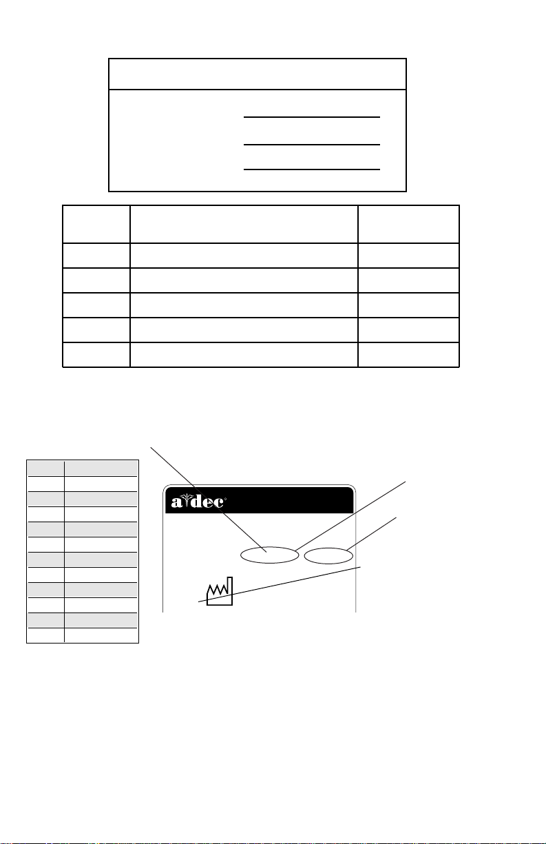
Warranty Information
Serial Number
Model Number
Date Purchased
Date of
Service
Model/Description of Service
Technician's
Initials
R
NEWBERG, OREGON 97132 USA
2601 CRESTVIEW DRIVE
Designated EU Representative: A-dec Dental U.K., Ltd.
Austin House, 11 Liberty Way, Attleborough Fields,
Nuneaton, Warwickshire, England CV116RZ
Tele: (44) 1203-350901
SN: J828287 REF: 2122
1993
ALPHABETICAL
EQUIVALENT TO THE
NUMERAL OF THE MONTH
MANUFACTURED
A January
B February
C March
D April
E May
F June
G July
H August
I September
J October
K November
L December
SERIAL
NUMBER
MODEL
NUMBER
YEAR
MANUFACTURED
1993
SERIAL NUMBER
IDENTIFICATION
Serial Number Location:
• Located on the underside of the control head.
For service information contact your local authorized A-dec dealer.
Check with local codes and A.D.A. (Americans with Disabilities
Act) Requirements for Installation of this product.
Page 3
A-dec warrants its products against defects in material or
®
workmanship for one year from time of delivery (except
for handpieces which have a warranty period of six
months). A-dec’s sole obligation under the warranty is to
provide parts for the repair, or at its option, to provide the
replacement product (excluding labor). The buyer shall
have no other remedy. (All special, incidental, and
coincidental damages are excluded.) Written notice of
breach of warranty must be given to A-dec within the
warranty period. The warranty does not cover damage
resulting from improper installation or maintenance,
accident or misuse. The warranty does not cover damage
resulting from the use of cleaning, disinfecting or
sterilization chemicals and processes. The warranty also
does not cover light bulbs. Failure to follow instructions
provided in A-dec’s Operation and Maintenance
Instructions (Owner’s Guide) may void the warranty.
NO OTHER WARRANTIES AS TO
MERCHANTABILITY OR OTHERWISE ARE MADE
Warranty
All product names used in this document are trademarks or
registered trademarks of their respective holders.
Printed in U.S.A .• Copyright © 1999• All Rights Reserved
Page 4
Cascade 3072 Handpiece Control System
1 2 3 4 5 6 7 8
Cascade 3072
Handpiece Control System
Page 5

Cascade 3072 Handpiece Control System
Serial Number Location, Service Information,
and Warranty Information are located on the
inside front cover and front page.
CONTENTS
Your Cascade Handpiece Control System .... 2
Handpiece Controls ...................................... 3
Master On/Off Toggle.............................. 3
Drive Air Pressure Gauge ........................ 4
Foot Control............................................. 5
Drive Air Pressure Controls ..................... 6
Coolant Air Flow Control........................ 7
Coolant Water Flow Controls.................. 8
Handpiece Tubing Flush ......................... 9
Handpiece Holder Positioning .............. 10
Handpiece Dry Block Conversion ......... 11
Oil Collector .......................................... 12
Autoclavable Syringe.................................. 13
System Air And Water
Pressure Adjustment.............................. 13
Care Instructions......................................... 13
Flexible Arm................................................ 14
Counterbalance Spring Adjustment ..... 14
Maintenance................................................... 16
Adjustments and Specifications ..................... 17
Identification of Symbols................................ 18
Classification of Equipment (EN 60601-1)..... 19
1
Page 6
Cascade 3072 Handpiece Control System
Your Cascade Handpiece Control System
Your Cascade 3072 Handpiece Control System
is built around A-dec’s Century Plus
system for three handpieces. The system also
includes the A-dec autoclavable syringe.
Handpiece activation is automatic. When you
lift a handpiece from its holder the handpiece
becomes active and will run when you press on
the foot control disc (refer to page 5).
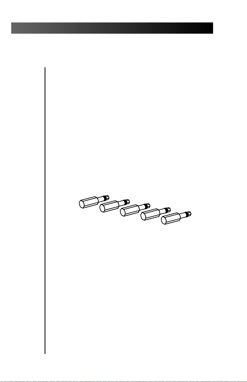
Adjustment keys (see Figure 1) are provided for
your use when making adjustments to the recessed
controls, including; coolant air, coolant water, and
handpiece flush. If the adjustment keys are ever
misplaced, you can use a 1⁄8" hex key. You may
order additional or replacement keys from your
authorized A-dec dealer.
Figure 1. Autoclavable Control Keys
®
control
2
Page 7
Cascade 3072 Handpiece Control System
1234
I MASTER O
PUSH
®
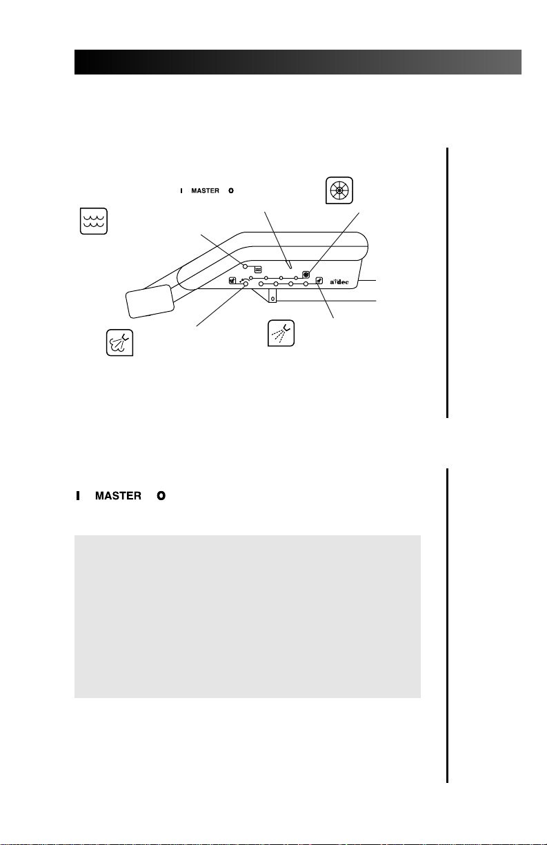
Handpiece Controls
HANDPIECE
FLUSH CONTROL
(see page 9)
COOLANT AIR
FLOW CONTROL
(see page 7)
MASTER
ON/OFF
TOGGLE
COOLANT WATER
FLOW CONTROLS
(see page 8)
DRIVE AIR
PRESSURE
CONTROLS
(see page 6)
Figure 2. Handpiece Controls
Master On/Off Toggle
The master on/off toggle
(see Figure 2) turns air, water, and
electricity on or off to the system.
CAUTION
The MASTER ON/OFF TOGGLE should be in the
OFF (0) position whenever the unit is not in use.
This will prevent the possibility of water damage
should a leak occur while the unit is unattended.
Making sure the unit is off will also prevent the
possibility of self-activation and the resulting burnout of your electrical accessories.
3
Page 8
Cascade 3072 Handpiece Control System
Drive Air Pressure Gauge
The drive air pressure gauge (see Figure 3) indicates,
in psi and kg/cm2, the drive air pressure to the
active handpiece (refer to page 6).
Figure 3. Drive Air Pressure Gauge
DRIVE AIR
PRESSURE
GAUGE
4
Page 9
Cascade 3072 Handpiece Control System
The foot control modulates drive air to the active
handpiece and provides an air signal that activates
the coolant air and coolant water flow. The foot
control is operated by light foot pressure applied to
any part of the foot control disc.
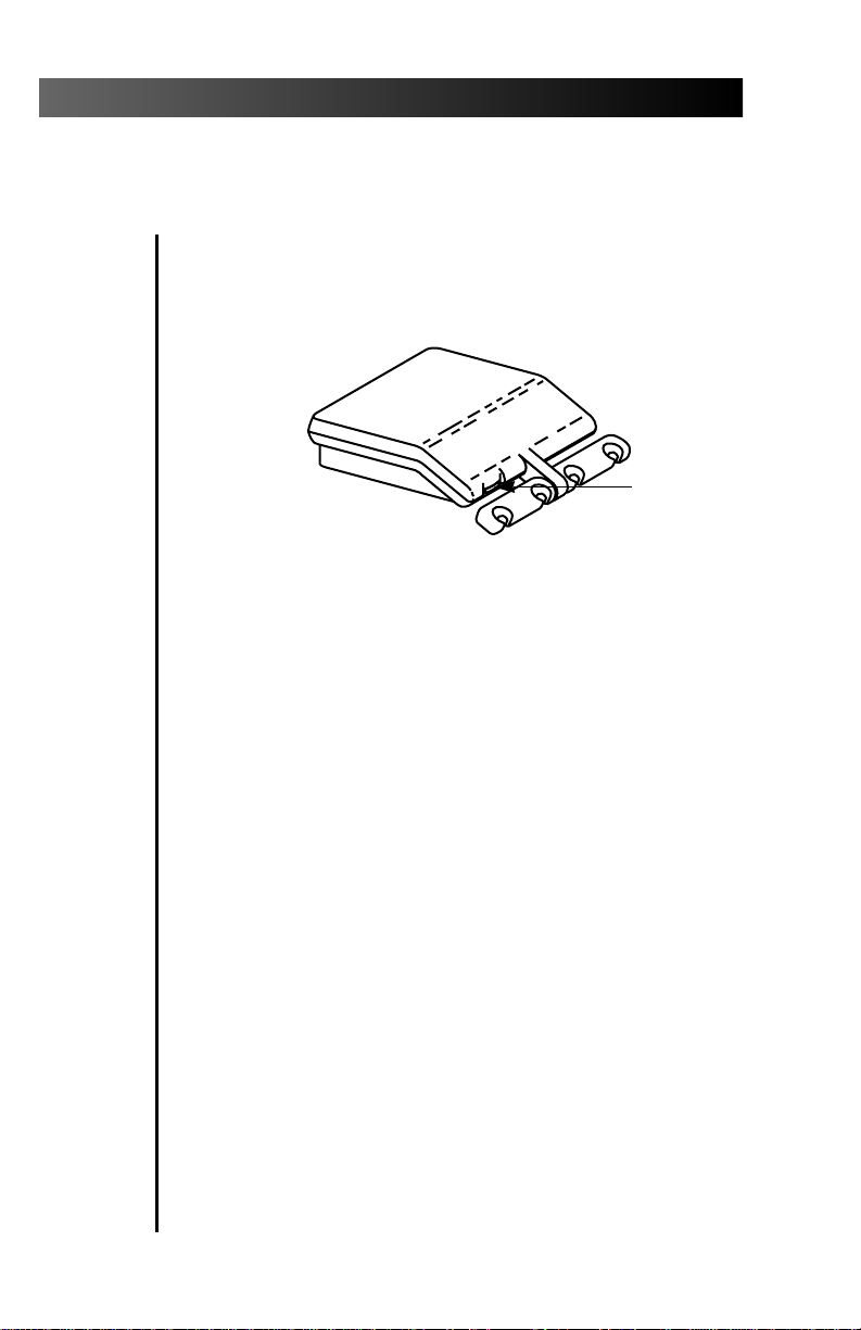
The foot control is equipped with a wet/dry toggle
and can be equipped with an optional chip blower
button (see Figure 4).
Foot Control
CHIP BLOWER
BUTTON
(Optional)
BLUE DOT
Figure 4. Foot Control
FOOT CONTROL DISC
WET/DRY TOGGLE
Wet/Dry Toggle. Allows you to shut off the
coolant water to the handpiece without moving
your hands from the oral cavity. Using your foot,
move the toggle away from the blue dot to turn
the coolant water OFF. Move the toggle toward the
blue dot to turn the coolant water ON.
Chip Blower Button. Sends a jet of air through
the handpiece when it is not running.
5
Page 10

Cascade 3072 Handpiece Control System
Drive Air Pressure Controls
The drive air pressure controls
on page 3)
are u
sed to adjust the drive air
(see Figure 2
pressure to each handpiece.
Adjust the drive air pressure to meet the
handpiece manufacturer’s dynamic drive air
pressure specification. Refer to the documentation
that came with your handpiece for the dynamic
drive air pressure specification.
You will need a 3⁄32" hex key to complete this adjustment.
1. Install a bur in the handpiece.
2. Locate the drive air gauge on the front of the
control head (see Figure 3 on page 4).
3. Move the wet/dry toggle on the foot control
(see Figure 4 on page 5) to the OFF position,
away from the blue dot).
4. Turn the drive air control clockwise until the
valve seats.
5. Fully depress the foot control disc.
6. While running the handpiece, watch the
drive air gauge and adjust the handpiece
dynamic drive air pressure to meet
manufacturer’s specifications.
• Turn the drive air control counterclockwise to
increase drive air pressure flow.
• Turn the control clockwise to decrease flow.
NOTE
Do not turn the control counterclockwise
beyond the point where the drive air pressure
no longer increases. The control adjustment
screw may come completely out of the unit.
7. Repeat steps 1 through 6 for EACH handpiece.
6
Page 11

Cascade 3072 Handpiece Control System
Coolant Air Flow Control
The coolant air flow control
(see Figure 2 on page 3) is used to adjust
the coolant air flow to all handpieces.
You will need an adjustment key (see Figure 1 on page 2)
or a 1⁄8" hex key to complete this adjustment.
1. Install a bur in the handpiece.
2. Locate the coolant air control (see Figure 2).
3. Move the wet/dry toggle on the foot control
(see Figure 4 on page 5) to the OFF position,
away from the blue dot.
4. Insert an adjustment key, or a 1⁄8" hex key,
into the coolant air flow control.
5. Fully depress the foot control disc to activate
the handpiece.
6. Adjust the coolant air flow to fit your needs.
A strong flow of air is recommended.
• Turn the control clockwise to decrease the flow.
• Turn counterclockwise to increase the flow.
7. The coolant air has been set for ALL handpieces.
7
Page 12

Cascade 3072 Handpiece Control System
Coolant Water Flow Controls
The coolant water flow controls are used
to adjust the flow of coolant water to
each handpiece
You will need an adjustment key (see Figure 1 on page 2)
or a 1⁄8" hex key to complete this adjustment.
1. Install a bur in the handpiece.
2. Locate the coolant water flow controls
(see Figure 2 on page 3).
3. Move the wet/dry toggle on the foot control
(see Figure 4 on page 5) to the ON position,
toward from the blue dot.
4. Insert an adjustment key, or a 1⁄8" hex key,
into the coolant water flow control for the
handpiece being adjusted.
5. Fully depress the foot control disc to activate
the handpiece.
6. Adjust the coolant water flow to fit your needs.
• Turn the control clockwise to decrease the flow.
• Turn counterclockwise to increase the flow.
(see Figure 2 on page 3)
.
7. Repeat steps 1 through 6 for EACH handpiece.
8
Page 13

Cascade 3072 Handpiece Control System
1
2
3
4
I MASTER O
PUSH
®
1
PUSH
Handpiece Tubing Flush
The handpiece tubing flush system
flushes more water through the tubings
in less time than is normally possible
when operating the foot control only.
The handpieces should not be connected
when flushing the tubings.
How Often Should the Handpiece Tubings be Flushed?
After Each Patient:
Flush the tubings for about 20-30 seconds.
At the Beginning of Each Day:
Flush the tubings for 2-3 minutes.
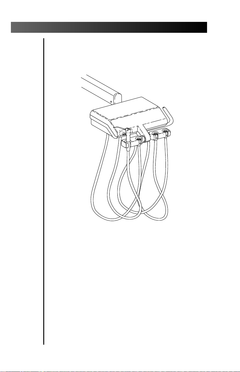
Flushing the Handpiece Tubings
Gather up all the handpiece tubings that use
coolant water and hold them over a sink, cuspidor
bowl or basin. Be sure you hold the tubings so that
the water will be directed away from you and into
the receptacle (see Figure 5).
Insert an adjustment key or 1⁄8" hex key into the
handpiece tubing flush control on the side of the
control head. Push in and hold the key for the
appropriate time required, either for flushing
between patients or flushing at the beginning of
each day, depending on the situation. Remove the
key and replace the tubings in their holders.
ADJUSTMENT
KEY
Figure 5. Handpiece Tubing Flush
9
Page 14

Cascade 3072 Handpiece Control System
PUSH
Handpiece Holder Tension Adjustment & Positioning
The holder tension was set at the factory. However; if
a holder is difficult to reposition or repositions too
easily, the holder tension can be adjusted.
To adjust the holder tension:
• Loosening or tightening the tension adjustment
screw shown in Figures 6A and 6B.
To reposition a holder:
• Rotate the holder to the desired angle.
1/8" HEX KEY
10
ROTATE THE HOLDER
FULL DOWN TO ACCESS
THE ADJUSTMENT SCREW
Figure 6A. Unitized Handpiece Holder
Figure 6B. Individual Handpiece Holder
Page 15
Cascade 3072 Handpiece Control System
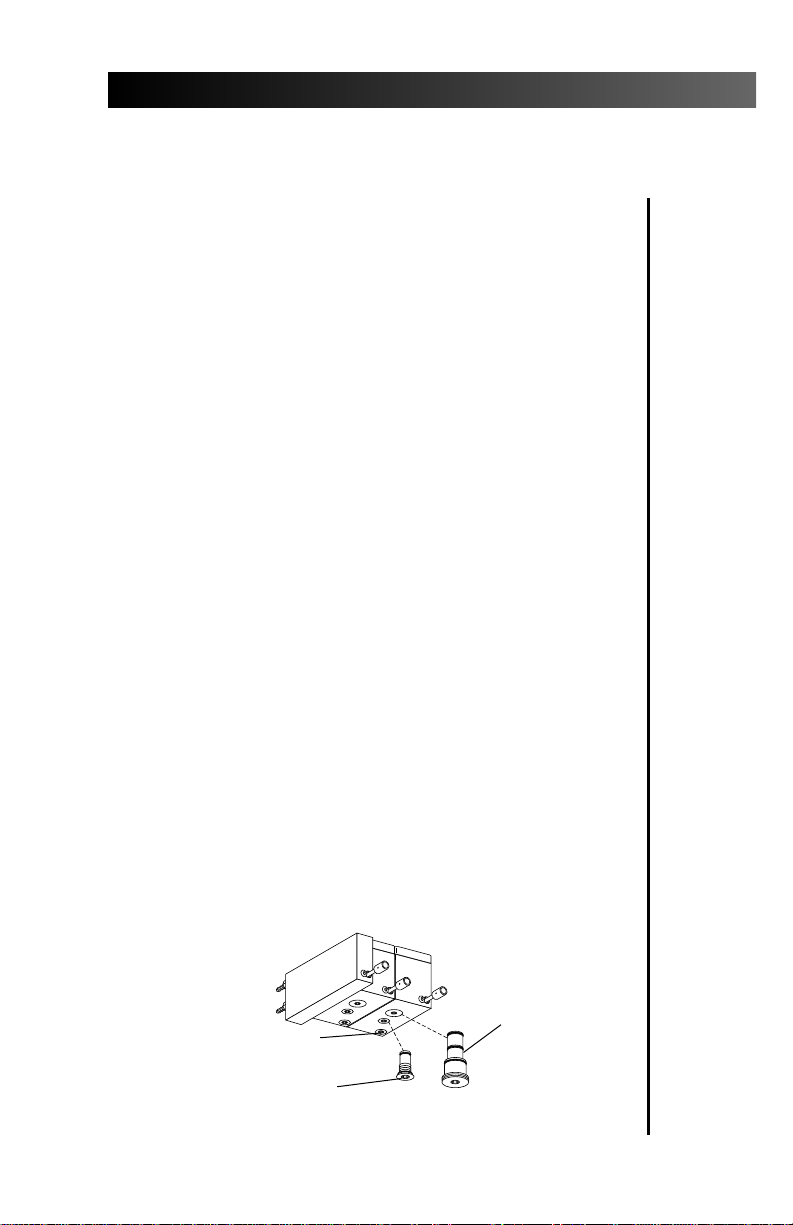
Handpiece Dry Block Conversion
Your Cascade handpiece control system has one to
four handpiece control blocks with coolant water to
the handpiece. In some cases a control block without
coolant water, a dry block, is required. If you require
a dry block (offering no water to the handpiece) on
your handpiece control system, a dry block
conversion kit has been included with your system.
Installing the Dry Block Conversion Kit
1.
Move the master on/off toggle to the OFF
position. Bleed the system water by operating
the syringe and flushing the handpiece tubings.
2. Locate the handpiece control block position
that will be the dry block. Access the control
blocks underneath the control head.
3.
Use a 3/32" hex key to remove the large red
cartridge from the control block. Install the large
black cartridge from the dry block conversion kit
into the control block (see Figure 7).
4.
Use a 3/32" hex key to remove the small blue
cartridge from the same control block. Install the
small black cartridge from the dry block
conversion kit into the control block (see Figure 7).
5. Turn your handpiece control system on, then
check the function of the dry block handpiece
conversion. A small amount of residual water
may be discharged from the handpiece tubing
but should dry after a few seconds.
REMOVE THE RED
CARTRIDGE AND
REPLACE WITH
THE LARGE BLACK
DO NOT REMOVE
THE YELLOW CARTRIDGE
REMOVE THE BLUE CARTRIDGE
AND REPLACE WITH THE
SMALL BLACK CARTRIDGE
Figure 7. Handpiece Dry Block Conversion
CARTRIDGE
11
Page 16

Cascade 3072 Handpiece Control System
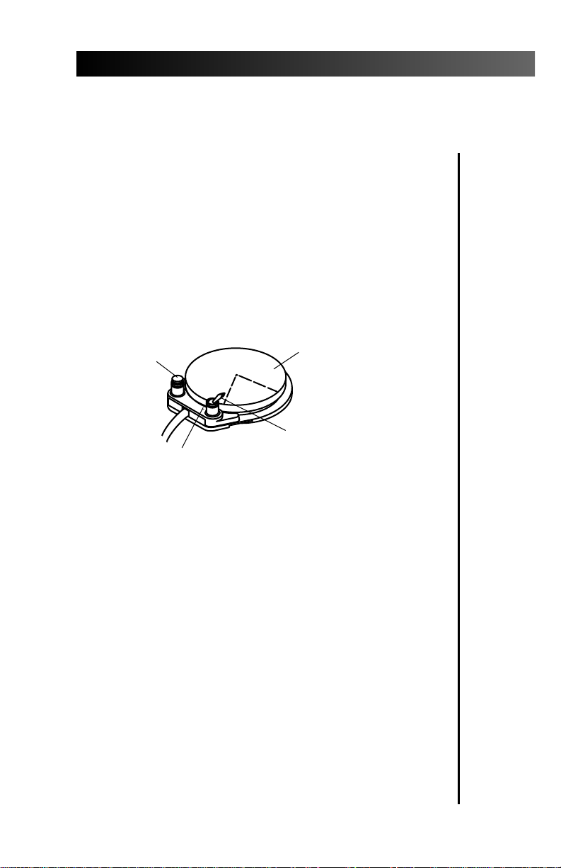
Oil Collector
The oil collector on your unit needs to be changed
once a week for normal usage. Change more often
for heavier use.
1. Remove the oil collector jar from the unit and
discard the old gauze (see Figure 8).
2. Fold in quarters a new two inch square gauze
pad and place against the spring inside the jar.
3. Screw the oil collector jar onto the unit. Do not
over tighten.
12
CONTROL HEAD
Figure 8. Oil Collector
Page 17

Cascade 3072 Handpiece Control System
Autoclavable Syringe
To operate the syringe (see Figure 9):
• Move the on/off toggle to the ON position.
• Air — Press the right button down.
• Water – Press the left button down.
• Spray – Press both buttons down.
AIR
Figure 9. Autoclavable Syringe
Refer to your Autoclavable Syringe Owner’s Guide
(A-dec Publication No. 85.0680.00) for complete
syringe operation and maintenance instructions.
WATER
SPRAY
System Air and Water
Pressure Adjustment
For system air and water pressure adjustments, refer
to your Floor Boxes Owner’s Guide(A-dec Publication
No. 85.2611.00).
Care Instructions
For recommended asepsis instructions, refer
to your Equipment Asepsis Owner’s Guide
(A-dec Publication No. 85.0696.00) .
For recommended self-contained water system
care, refer to A-dec Self-contained Water System
Owner’s Guide (A-dec Publication No. 85.0675.00).
13
Page 18

Cascade 3072 Handpiece Control System
Flexible Arm
Cascade 3072 Handpiece Control Systems are
available on A-dec’s flexible arm system. The
flexible arm allows vertical and horizontal
positioning of the control head to suit your
practice.
Counterbalance Spring Adjustment
The flexible arm contains a spring that
counterbalances the weight of the control
head. The arm also contains a friction
mechanism to stabilize the arm at the
upper and lower extremes of its vertical arc.
If the arm tends to rise or drop when the arm
brake is released, the counterbalance spring
needs adjustment.
1. Remove the flexible vinyl cover from the
underside of the arm (see Figure 10). Gently
pull the tubing and wiring in the arm
slightly aside.
14
PULL DOWN ON ONE END
Figure 10. Flex Arm Cover
Page 19
Cascade 3072 Handpiece Control System
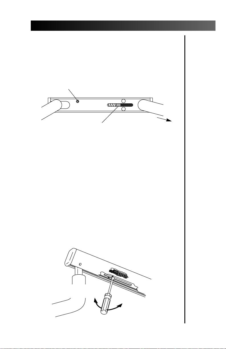
2. Raise the control head end of the flex arm until
the friction adjustment socket head screw is
accessible through the access hole in the arm (see
Figure 11). Using a 5⁄32" hex key loosen, but do
not remove, the friction adjustment.
FRICTION ADJUSTMENT ACCESS
CONTROL
SPRING TENSION
ADJUSTMENT NUT
HEAD
Figure 11. Tension Adjustment Locations
3. If the arm tends to drop, use a flat-blade
screwdriver to turn the spring tension
adjustment nut clockwise (as viewed from the
control end of the arm, see Figure 12). If the
arm tends to rise, turn the adjustment nut
counterclockwise. Lift the control end of the
flex arm as high as possible while turning the
adjustment nut, this relieves the spring tension
allowing the nut to turn more easily.
4. While adjusting the spring tension, frequently
move the arm through its vertical arc to see if it
is adjusted properly.
TO TURN THE ADJUSTMENT
NUT COUNTERCLOCKWISE
TO TURN THE
ADJUSTMENT
NUT CLOCKWISE
Figure 12. Spring Tension Adjustment
15
Page 20

Cascade 3072 Handpiece Control System
Counterbalance Spring Adjustment (continued)
5. When you are satisfied with the spring tension
adjustment, move the arm alternately full up
and then full down positions releasing the
control head at each position. If the arm drops
or rises when you let go of it in either position,
tighten the friction adjustment. Be careful not
to overtighten the adjustment as you may
damage the friction mechanism.
6. Reinstall the flex vinyl cover (see Figure 13).
The cover is easily snapped back into place.
Start by inserting one end of the cover into
the arm and press it into place along the
bottom of the arm.
Maintenance
Handpiece Flush ..............................................page 9
Oil Collector .....................................................page 12
Also refer to the following A-dec documentation
for more maintenance information:
Autoclavable Syringe
Care Instructions
Power Supplies
16
Figure 13. Install the Flex Arm Cover
Autoclavable Syringe
Owner’s Guide......................................85.0680.00
Equipment Asepsis
Owner’s Guide......................................85.0696.00
Self-contained Water
Owner’s Guide......................................85.0675.00
Floor Boxes
Owner’s Guide......................................85.2611.00
Page 21

Cascade 3072 Handpiece Control System
Adjustments and Specifications
Handpiece Controls
Drive Air Pressure ......................................page 6
(Refer also to your handpiece documentation for the
manufacturer’s maximum dynamic drive air pressure
specification.)
Coolant Air Flow .......................................page 7
Coolant Water Flow ..................................page 8
Handpiece Holder .....................................page 10
Flex Arm Adjustments
Counterbalance Springe ...........................page 14
Service Requirements for Unit Operation:
Minimum Air:
2.50 cfm (70.80 l/min) at 80 psi (551 kPa)
Minimum Water:
1.50 gpm (5.68 l/min) at 40 psi (276 kPa)
Minimum Vacuum:
12 cfm (339.84 l/min)
at 8 inches of mercury (27 kPa)
Wall Mount Specifications:
100 lb (45.36 kg) maximum unit weight.
100 ft-lb (136 N·m) maximum moment
created at the wall by the freestanding unit.
Weights of optional attachments:
Touch Pad: .5 lb (.23 kg)
Tooth Dryer: 1 lb (.45 kg)
Intra-Oral Light Sources: 1 lb (.45 kg)
Scaler: 2 lb (.91 kg)
Curing Light: 3 lb (1.36 kg)
Any optional non-A-dec attachments and/or accessories
must comply with EN 60601-1 and EN 60601-1-2.
Also refer to the following A-dec documentation for
more adjustment and specification information:
System Air and Water Pressure Adjustments
Floor Box
Owner’s Guide......................................85.2611.00
Specifications are subject to change without notice.
17
Page 22
Cascade 3072 Handpiece Control System
LISTED
®
!
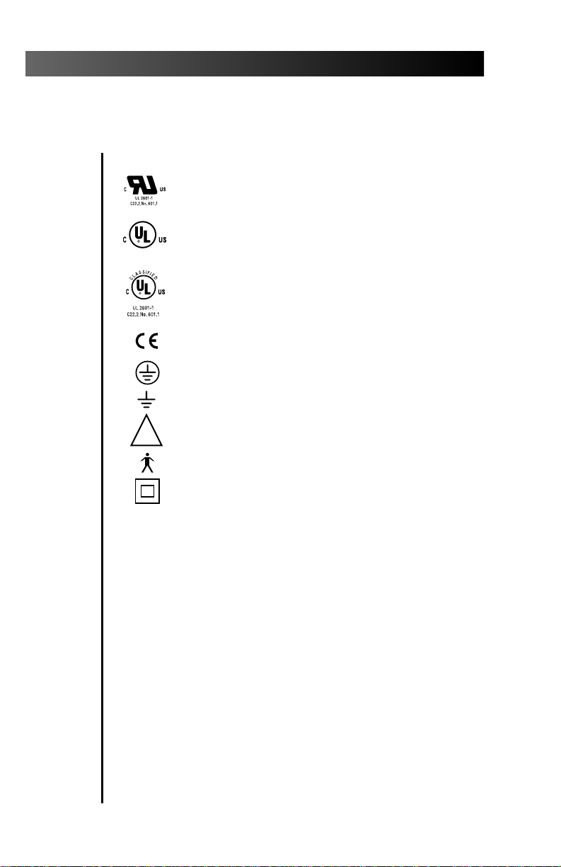
Identification of Symbols
Recognized by Underwriters Laboratories Inc. ® with respect to
electric shock, fire and mechanical hazards only in accordance
with UL 2601-1. Recognized with respect to electric shock, fire,
mechanical and other specified hazards only in accordance with
CAN/CSA C22.2, No. 601.1.
UL listed to US (UL 544) and Canadian (CAN/CSA C22.2, No.
125) safety standards.
Classified by Underwriters Laboratories Inc. ® with respect to
electric shock, fire and mechanical hazards only in accordance
with UL 2601-1. Classified with respect to electric shock, fire,
mechanical and other specified hazards only in accordance with
CAN/CSA C22.2, No. 601.1.
Conforms to European Directives
Protective earth (ground).
Functional earth (ground).
Attention, consult accompanying documents.
TYPE B APPLIED PART.
CLASS II EQUIPMENT.
(refer to Declaration Statement)
18
Page 23

Cascade 3072 Handpiece Control System
Classification of Equipment (EN 60601-1)
Type of shock protection:
CLASS I EQUIPMENT
(Dental Chairs, Dental Lights, & Power Supplies)
CLASS II EQUIPMENT
(Chair, Wall, & Cart Mounted Delivery Systems)
Degree of shock protection:
TYPE B APPLIED PART (All products)
Degree of protection against water ingress:
ORDINARY EQUIPMENT (All products)
Mode of operation
CONTINUOUS OPERATION
(All models except Dental Chairs)
Mode of operation
CONTINUOUS OPERATION WITH
INTERMITTENT LOADING (Dental Chairs)
19
Page 24
2601 Crestview Drive
®
Newberg, Oregon 97132 U.S.A.
Telephone 1-800-547-1883
(503) 538-7478
Fax (503) 538-0276
Designated Representative’s Address:
A-dec Dental U.K., Ltd.
Austin House
11 Liberty Way
Attleborough Fields,
Nuneaton, Warwickshire.
England. CV11 6RZ.
Telephone: 00 44 24 7635 0901
Fax: 00 44 24 7634 5106
Designated Representative’s Address:
A-dec Australia
41-43 Bowden Street
Alexandria, N.S.W. 2015, Australia
Telephone: (61) 1.800.225010
85.2620.00
1999-03
Rev F (00480)
Made with 50% waste paper
Printed in USA.
Copyright © 1999,
All Rights Reserved.
 Loading...