

Page 1
Owner's Guide
AUTOCLAVABLE
SYRINGE
85.0680.00
®
Page 2
Warranty Information
N/A
N/A
For service information contact your local authorized A-dec dealer.
Check with local codes and A.D.A. (Americans with Disabilities Act)
Requirements for Installation of this product.
Serial Number
Model Number
Date Purchased
Date of
Service
Model/Description of Service
Technician's
Initials
Page 3
Warranty
Printed in U.S.A. • Copyright © 1999 • All Rights Reserved
A-dec warrants its products and A-dec/W&H Synea
handpieces against defects in material or workmanship
for one year from time of delivery. All other handpiece
instrumentation has a warranty period of six months.
A-dec’s sole obligation under the warranty is to provide
parts for the repair, or at its option, to provide the
replacement product (excluding labor). The buyer shall
have no other remedy. (All special, incidental, and
coincidental damages are excluded.) Written notice of
breach of warranty must be given to A-dec within the
warranty period. The warranty does not cover damage
resulting from improper installation or maintenance,
accident or misuse.The warranty does not cover damage resulting from the use of cleaning, disinfecting or
sterilization chemicals and processes. The warranty also
does not cover light bulbs. Failure to follow instructions
provided in A-dec’s Operation and Maintenance
Instructions (Owner’s Guide) may void the warranty.
NO OTHER WARRANTIES AS TO
MERCHANTABILITY OR OTHERWISE ARE MADE.
All product names used in this document are trademarks or
registered trademarks of their respective holders.
®
Page 4
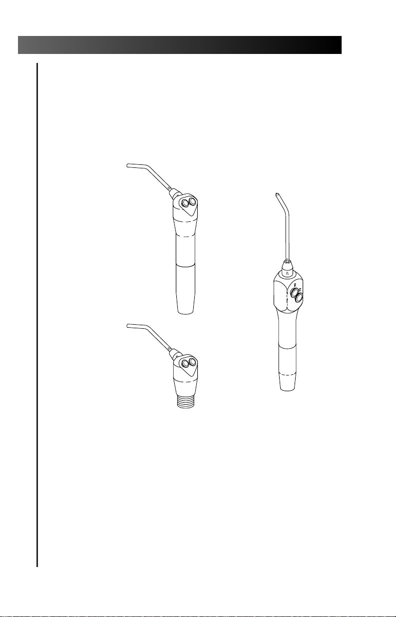
Autoclavable Syringe
Autoclavable
Syringe
Autoclavable
Continental
Autoclavable
Easy-Clean
Syringe Head
Page 5

Serial number location, service information, and
warranty information are located on the inside
front cover and front page.
About Your Autoclavable Syringe............................ 2
Installation ......................................................... 2
Button Functions ................................................ 3
Syringe Tip Retainer Assembly
(Non-locking) ................................................. 3
Optional Configurations ................................... 4
A-dec Syringe Tips..................................................... 5
Installing an A-dec Syringe Tip ......................... 6
Removing an A-dec Syringe Tip ........................ 7
Syringe Air and Water Flow Control ........................ 8
Doctor’s Syringe.................................................. 8
Assistant’s Syringe............................................ 10
Disconnecting the Syringe Head ............................ 11
Locking Syringe Tip Retainer Assembly................. 12
Installing an A-dec Syringe Tip ....................... 12
Restricting Tip Rotation.................................... 14
Removing an A-dec Syringe Tip ...................... 15
Heated Syringe Tubing with
In-line Low Voltage Water Heater............... 16
Quick Disconnect Syringe Terminal ...................... 17
Syringe and Tip Asepsis .......................................... 18
Pre-Cleaning...................................................... 18
Sterilization....................................................... 19
General Information............................................... 20
Using A-dec Silicone Lubricant ......................... 20
Using A-dec Replacement Parts....................... 20
Maintaining Syringe Tip
Retainer Assemblies ..................................... 21
Troubleshooting...................................................... 21
Adjustments and Specifications ............................. 25
Maintenance........................................................... 25
Identification of Symbols........................................ 26
Classification of Equipment (EN 60601-1)............. 26
1
Autoclavable Syringe
CONTENTS
Page 6

Your Autoclavable Continental or
Autoclavable Easy-Clean Syringe is a threeway air and water syringe featuring a patented
quick disconnect autoclavable tip system.
1. Turn off the unit’s master switch.
2. Purge the water and air lines by holding the
syringe over a sink or basin and pressing the
water and air buttons.
3. Disconnect the old syringe by turning the tubing
connector nut counterclockwise.
4. Separate the syringe and tubing.
5. Connect the A-dec syringe to the tubing and
turn the nut clockwise until it is finger tight.
6. Depress separately the air and water buttons to
verify air and water flow.
7. Depress both the air and water buttons
simultaneously to verify desired spray pattern.
If a change of flow is desired, see Syringe Air
and Water Flow Control on page 8.
2
Autoclavable Syringe
OPERATION
About Your New Autoclavable Syringe
Installation
Page 7
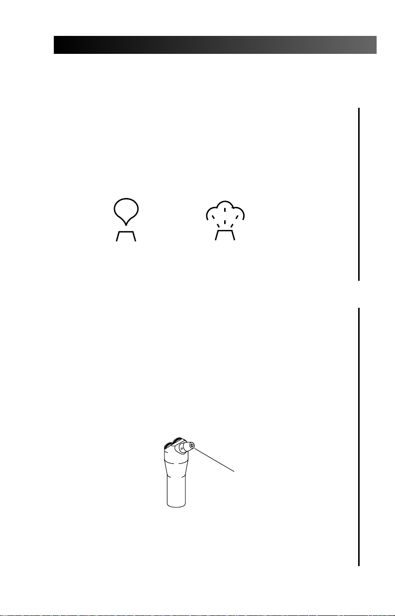
All three syringes feature two buttons that provide
three-way, modulated control of syringe water, air,
and spray functions.
The button functions are indicated with
internationally recognized icons for air and water
(see Figure 1).
All three syringe heads are factory equipped
with a non-locking syringe tip retainer assembly.
This style of syringe tip retainer (identified by a
smooth exterior surface, see Figure 2) allows the
syringe tip to be easily removed and installed.
The non-locking syringe tip retainer assembly is
not appropriate for use as cheek retractor
because it allows the syringe tip to rotate.
3
Autoclavable Syringe
Button Functions
Water Air
Figure 1. Water and Air Icons
Syringe Tip Retainer Assembly (Non-Locking)
Figure 2. Syringe Tip Retainer Assembly
(Non-Locking)
SMOOTH
EXTERIOR
SURFACE
Page 8

Locking Syringe Tip Retainer Assembly
The syringe tip may be locked in place, allowing
it to be used for cheek retraction, when the locking
syringe tip retainer assembly option has been
ordered. Refer to page 12 for further information.
Heated Syringe Water
Warm water may be delivered through the
syringe, eliminating the discomfort that can be
caused by spraying cold water on sensitive tissues,
when either the circulating warm water or heated
syringe tubing option has been ordered. Refer to
pages 15 through 17 for further information.
Quick Disconnect Syringe Terminal
The syringe head may be removed from the
syringe tubing without shutting the delivery
system unit off when the quick disconnect syringe
terminal option has been ordered. Refer to page 17
for further information.
4
Autoclavable Syringe
Optional Configurations
Page 9
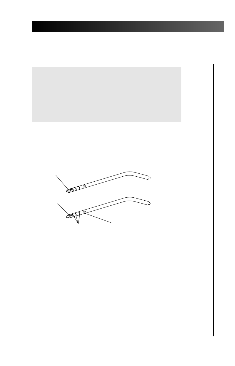
Your syringe is packaged with two specially
designed A-dec syringe tips. These tips have three
grooves and a distinguishing “O” or “I” and an
A-dec “a” marking (see Figure 3).
5
Autoclavable Syringe
A-dec Syringe Tips
Figure 3. Specially Designed A-dec Syringe Tip
THREE GROOVES
DISTINGUISHING “O” MARK
DISTINGUISHING “I” MARK
DISTINGUISHING A-DEC
“a” MARK
Warning
USE ONLY A-DEC SYRINGE TIPS.
A-dec syringe tips have been engineered and manufactured for use with A-dec syringes. Using syringe
tips manufactured by a company other than
A-dec can result in syringe tip ejection.
Page 10
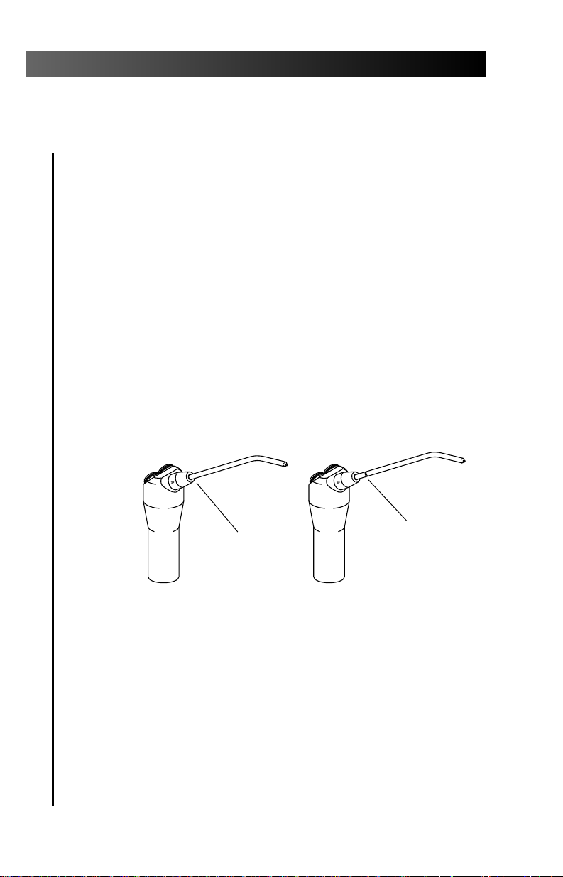
To ensure that the syringe will perform properly, it
is important that you install the tip correctly.
Push the syringe tip into the syringe tip retainer
assembly. As you push the tip in you will feel two
“clicks” as O-rings inside the syringe tip retainer
assembly slide into the grooves. If you do not feel
two “clicks” when installing the syringe tip, do not use
the syringe. The O-rings inside the syringe tip
retainer assembly are damaged and may allow
the syringe tip to be ejected. The syringe tip
retainer assembly must be repaired prior to using
the syringe.
When properly installed none of the grooves on
the A-dec syringe tip are visible (see Figure 4).
After installing a tip, point the syringe at the
floor and press the air button several times to be
sure the tip is properly installed.
An improperly installed A-dec syringe tip allows
water to enter the air tubing in the syringe tip.
6
Autoclavable Syringe
Installing an A-dec Syringe Tip
Figure 4. Installing the A-dec syringe tip
NO GROOVES
ARE SHOWING.
THIS TIP IS
PROPERLY
INSTALLED.
A GROOVE IS
SHOWING. THIS TIP
IS IMPROPERLY
INSTALLED.
CORRECT INCORRECT
Page 11

To remove the A-dec syringe tip, pull it straight out
of the syringe tip retainer assembly (see Figure 5).
7
Autoclavable Syringe
Removing an A-dec Syringe Tip
Figure 5. Removing an A-dec syringe tip
Page 12

Cascade®Delivery Systems.
Syringe air and water flow is controlled by flow
control valves inside the handpiece control unit
(see Figure 6). To adjust the flow, turn the hex body of
the flow control valve clockwise to reduce flow or
counterclockwise to increase flow. Press both syringe
buttons to test the spray.
8
Autoclavable Syringe
Syringe Air and Water Flow Control
Doctor’s Syringe
Figure 6. Flow Control Valves
AIR FLOW CONTROL VALVE
WATER FLOW CONTROL VALVE
Caution
Flow adjustment valves and screws are not
intended to completely stop the air and water.
Forcing the screws to turn beyond their limit will
damage the flow adjustment valves.
A
L
W
L
D
A
D
W
Page 13

Excellence®, Decade®, Mini-Trol®, and
Auto-Trol
®
Delivery Systems.
Syringe air and water flow is controlled by flow
adjusting screws in the faceplate or side of the
handpiece control unit (see Figure 7). To adjust
the flow (with a 3/32-inch hex key), turn the
adjustment screw clockwise to reduce flow or
counterclockwise to increase flow. Press both
syringe buttons to test the spray.
Solo and Older A-dec Delivery Systems
Syringe air and water flow is controlled by pinch
valves (see Figure 8) inside the chair back or inside the
handpiece control unit. To adjust the flow, turn the
adjustment screw clockwise to reduce flow or counterclockwise to increase flow. Press both syringe buttons
to test the spray.
9
Autoclavable Syringe
Figure 8. Pinch Valves
Figure 7. Flow Adjusting Screws
DECREASE
AIR ADJUSTMENT
SCREW
WATER ADJUSTMENT
SCREW
INCREASE
WATER
TUBING
ADJUSTMENT
SCREWS
AIR
TUBING
(ribbed)
Page 14

Syringe air and water flow is controlled either by
pinch valves (see Figure 9) or a syringe block (see
Figure 10). These controls are located inside the
post box, floor box, chair back, or inside a cabinet
(depending upon the application). To adjust the
flow through a pinch valve, turn the adjustment
screw clockwise to reduce flow or counterclockwise
to increase flow. To adjust the flow through a
syringe block use a 3/32-inch hex key to turn the
adjustment screw clockwise to reduce flow or
counterclockwise to increase flow. Press both
syringe buttons to test the spray.
10
Autoclavable Syringe
Assistant’s Syringe
Figure 10. Syringe Block
ADJUSTMENT
SCREWS
AIR TUBING
(ribbed)
WATER TUBING OMITTED FOR CLARITY
Caution
Flow adjustment valves and screws are not
intended to completely stop the air and water.
Forcing the screws to turn beyond their limit will
damage the flow adjustment valves.
Figure 9. Pinch Valves
WATER
TUBING
ADJUSTMENT
SCREWS
AIR
TUBING
(ribbed)
Page 15

To disconnect your syringe head from the syringe
tubing, move the master on/off toggle to the OFF
position. Use the syringe to bleed the system of air
and water pressure.
Turn the syringe handle counterclockwise until
the syringe separates from the handle then pull
the syringe head away from the terminal.
When the syringe head is disconnected, a little
water, which is left inside of the syringe head and
tubing, will drip out.
11
Autoclavable Syringe
Disconnecting the Syringe Head
Page 16

The syringe heads may be optionally equipped
with a locking syringe tip retainer assembly . This
style of syringe tip retainer assembly (identified by a
hex shaped exterior, see Figure 11) functions like the
standard syringe tip retainer assembly (smooth
shaped exterior) but allows the retaining nut to be
tightened, preventing the tip from easily
rotating.
The tip can then be used for cheek retraction.
Your syringe is packaged with two specially
designed A-dec syringe tips. These tips have three
grooves and a distinguishing “O” or “I” and an
A-dec “a”marking (see Figure 3 on Page 5).
12
Autoclavable Syringe
OPTIONAL CONFIGURATIONS
Locking Syringe Tip Retainer Assembly
Installing an A-dec Syringe Tip
Warning
USE ONLY A-DEC SYRINGE TIPS.
A-dec syringe tips have been engineered and manufactured for use with A-dec syringes. Using syringe
tips manufactured by a company other than A-dec
can result in syringe tip ejection.
Figure 11. Locking Syringe Tip Retainer Nut
HEX-SHAPED
EXTERIOR
SURFACE
Page 17

To ensure that the syringe will perform properly,
it is important that you install an A-dec syringe
tip correctly.
Push the syringe tip into the syringe tip retainer
assembly. As you push the tip in, you will feel two
“clicks” as O-rings inside the syringe tip retainer
assembly slide into the grooves. When properly
installed, none of the grooves on the A-dec syringe
tip are visible (see Figure 12).
After installing a tip, point the syringe at the
floor and press the air button several times to be
sure the tip is properly installed.
An improperly installed A-dec syringe tip allows
water to enter the air tubing in the syringe tip.
13
Autoclavable Syringe
Caution
Be sure the hex portion of the syringe tip retainer
assembly is loose before installing an A-dec
syringe tip.
If you attempt to force the tip into the syringe tip
retainer assembly, you will damage the internal
collet of the retainer and make it difficult or
impossible to properly install a tip, remove a tip,
or use your syringe.
Figure 12. Installing an A-dec syringe tip
NO GROOVES
ARE SHOWING.
THIS TIP IS
PROPERLY
INSTALLED.
A GROOVE IS
SHOWING. THIS TIP
IS IMPROPERLY
INSTALLED.
CORRECT INCORRECT
Page 18

Your syringe tip rotates to spray in different
directions. However, if you use your syringe tip for
cheek retraction and you have the hex-shaped
syringe tip retainer nut, you may prefer to adjust
the tip so that it does not rotate easily.
To adjust the installed syringe tip so that it does
not rotate easily, simply tighten the hex portion of
the syringe tip retainer assembly (see Figure 13).
Tighten only until you cannot easily rotate the tip.
14
Autoclavable Syringe
Restricting Tip Rotation
Caution
Tighten the syringe tip retainer assembly nut by
hand or with the plastic wrench provided.
Overtightening the nut will make it more
difficult to remove the syringe tip later—use
only as much force as needed to keep the
syringe tip from rotating easily.
Never tighten the syringe tip retainer assembly nut
when a syringe tip is improperly installed. The
internal collet will be crushed making removal of
the tip difficult and proper installation of a new
tip impossible.
Figure 13. Eliminating Tip Rotation
BE SURE THE TIP IS
PROPERLY INSTALLED.
ROTATE THE NUT
COUNTERCLOCKWISE
TO ADJUST THE TIP SO
THAT IT DOES NOT
ROTATE FREELY.
SEE CAUTION ABOVE.
Page 19

To remove the A-dec syringe tip, turn the tip
retainer nut counterclockwise until it turns easily,
no more than a 1/4 turn. Then pull the A-dec tip
straight out of the syringe tip retainer (see Figure 14).
15
Autoclavable Syringe
Removing an A-dec Syringe Tip
Figure 14. Removing the A-dec Tip
RETAINER
NUT
Page 20

Water temperature at the syringe is controlled by
the use of an in-line water heater (see Figure 15)
and resistance wiring in the syringe tubing.
To determine if you have this type of warm water
syringe, look for the in-line water heater (see Figure 15
on page 15) in the control head or in the post box.
Additionally, the syringe tubing will be warm to
the touch after the unit has been turned on for a
few minutes.
The water temperature is not adjustable. The
water should feel lukewarm on the back of your
hand. If the water temperature is too warm or
cold, contact your factory authorized A-dec dealer.
16
Autoclavable Syringe
Heated Syringe Tubing with
In-line Low Voltage Water Heater
Figure 15. In-line Low Voltage Water Heater
Made in USA
85-0966-00
INLINE WATER HEATER
Part # 40-1060-00
24 VAC 4 AMPS
5/93
Page 21

Your A-dec syringe tubing may be optionally
equipped with a quick disconnect syringe
terminal (see Figure 16). This terminal allows you
to remove the syringe head without shutting the
delivery system off.
To remove the syringe head, turn the syringe
handle counterclockwise until the syringe separates
from the handle then pull the syringe head away
from the terminal.
17
Autoclavable Syringe
Quick Disconnect Syringe Terminal
Figure 16. Quick Disconnect Syringe Terminal
STANDARD
QUICK
DISCONNECT
TERMINAL
CIRCULATING
SYRINGE
QUICK
DISCONNECT
TERMINAL
Page 22

All syringe tips are considered critical items and
must be heat sterilized between patients. The
syringe and syringe tips have been designed to be
heat sterilized.
1. Remove the syringe head and tip from the
syringe terminal.
2. If the threads on the syringe head appear dirty,
gently brush the threads free of debris using a
nylon or brass bristle brush.
3. Remove the syringe tip for sterilization.
18
Autoclavable Syringe
Syringe and Tip Asepsis
ASEPSIS
Pre-Cleaning
Warning
When cleaning syringe tips, do not use cleaning
solutions which contain ammonia or amines.
These chemicals are harmful to the brass
syringe tips and can cause possible damage and
tip ejection.
Note
To ease the removal and assembly of the
syringe head and the syringe nut, periodically
check the threads on the syringe head for
accumulated debris.
Page 23

4. Immerse the tip in an appropriate holding
solution until ready for ultrasonic cleaning.
5. Clean the syringe tips ultrasonically. Follow
the instructions provided by the manufacturer
of your ultrasonic cleaning equipment.
6. Purge all cleaning agents from the syringe
and syringe tips by vertically holding under
running water.
1. Rinse the syringe and syringe tips in clear water.
2. Use a dispensing bottle to flush isopropyl alcohol
or Harvey’s Vapo-Steril
®
through the tips.
3. Sterilize the syringe tips and/or syringe:
Sterilize SYRINGE TIPS using the methods of
steam autoclave, dry heat, or chemical vapor
(275°F [135°C] maximum temperature).
Sterilize the SYRINGE using the methods of
steam autoclave or chemical vapor
(275°F [135°C] maximum temperature).
19
Autoclavable Syringe
Sterilization
Caution
Sterilizing equipment at higher temperatures
will reduce the seal life of the O-rings.
Page 24

Your syringe is designed to be easily serviced in the
operatory. The syringe parts subject to wear under
normal use are provided in a syringe repair kit which
can be ordered from your authorized A-dec dealer.
Proper care and maintenance of your A-dec Syringe
is critical in ensuring the safety of your patients
and the reliability of this precision instrument.
Use only A-dec Silicone Lubricant when
performing maintenance on your A-dec syringe.
The O-rings used in the syringe head and
syringe tip retainer assembly are a compound
(Ethylene Propylene) which best resists the
autoclave process.
The use of petroleum based lubricants (jellies,
creams, or lotions) will cause the O-rings in the
syringe to swell and/or deteriorate, resulting in
syringe malfunction or failure.
Use only A-dec replacement parts when
performing maintenance on your A-dec syringe.
A-dec replacement parts have been precisely
designed for your A-dec syringe and ensure that
the syringe will function properly.
20
Autoclavable Syringe
MAINTENANCE
General Information
Using A-dec Silicone Lubricant
Using A-dec Replacement Parts
Page 25

As a means of preventive maintenance, A-dec
recommends replacing the two internal O-rings
and the small O-rings in the syringe tip retainer
assembly at least once a year (see Figure 17). Please
lubricate the O-rings with A-dec silicone lubricant
at the time of replacement.
The syringe is leaking from a button.
Replace the valve assembly.
The syringe is leaking from the end of the tip
while the syringe is not in use.
The valve assembly is damaged and must
be replaced.
21
Autoclavable Syringe
Troubleshooting
Maintaining Syringe Tip Retainer Assemblies
INTERNAL
O-RINGS
SMALL O-RING
BRASS
ADAPTER
BRASS
ADAPTER
SMALL O-RING
INTERNAL
O-RINGS
Figure 17. Syringe Nut Retainer Assemblies
NON-LOCKING
RETAINER ASSEMBLY
LOCKING
RETAINER ASSEMBLY
Page 26

There is a spray of water from the tip when the air
button is pressed.
1. Is the A-dec syringe tip properly installed?
YES: Install a different syringe tip and test the
syringe. If this solves the problem, discard
the damaged syringe tip. If there is still a
momentary spray of water from the tip
when the air button is pressed, replace the
small O-ring in the brass adapter section
of the syringe nut retainer assembly (see
Figure 17 on page 21) or replace the
syringe nut retainer assembly.
NO: Ensure that the syringe tip is properly
installed, then retest the syringe.
There is leakage from the syringe handle.
1. Is the syringe tightly connected to the
syringe tubing?
YES: The O-rings on the terminal connector tubes
(inside the syringe handle) are damaged
and must be replaced (see Figure 18).
NO: Ensure that the syringe and the syringe
tubing connector are tightly screwed
together and retest the syringe.
22
Autoclavable Syringe
Figure 18. Syringe Terminal Assemblies
O-RINGS
O-RINGS
Page 27

Air is leaking around the syringe tip at the top of
the syringe tip retainer assembly.
1. Is the A-dec syringe tip damaged?
YES: Install a different syringe tip and test the
syringe. If this solves the problem, discard
the damaged syringe tip.
NO: The two syringe tip retainer assembly
internal O-rings are damaged (see Figure
17 on page 21). Replace the O-rings or the
syringe tip retainer assembly.
Water is leaking around the base of the syringe
tip retainer assembly.
1. Is the syringe tip retainer assembly tightly
installed in the syringe head?
YES: The small O-ring in the brass adapter
section of the syringe tip retainer
assembly has failed (see Figure 17 on
page 21). Replace the O-ring or replace
the syringe tip retainer assembly.
NO: Tighten the syringe tip retainer assembly
and retest the syringe.
The syringe tip is difficult to install.
1. Has a petroleum based lubricant been used
to lubricate the syringe tip retainer assembly
internal O-rings (see Figure 17 on page 21)?
YES: The two syringe tip retainer assembly
internal O-rings are damaged. Replace
the O-rings or the syringe tip retainer
assembly.
NO: The syringe tip retainer assembly has
been damaged and must be replaced.
Do not use the syringe until the syringe
tip retainer assembly has been replaced.
23
Autoclavable Syringe
Page 28

The syringe tip is too easily removed from the
syringe nut retainer assembly.
1. Are you using an A-dec syringe tip? Ensure
that syringe tip being used is an A-dec syringe
tip (see Figure 3 on page 5).
YES: The two syringe tip retainer assembly
internal O-rings have been damaged or
worn (see Figure 17 on page 21). Replace
the O-rings or the syringe tip retainer
assembly.
NO: Properly install an A-dec syringe tip and
retest the syringe.
24
Autoclavable Syringe
Page 29

Installing an A-dec Syringe Tip .......................page 6 and 12
Syringe Air and Water
Flow Control .............................................................page 8
Restricting Tip Rotation .............................................page 14
Heated Syringe Tubing with
Inline Low Voltage Water Heater ..........................page 16
Syringe Tip Asepsis ....................................................page 18
Sterilization ................................................................page 19
Troubleshooting...........................................................page 21
Specifications are subject to change without notice.
25
Autoclavable Syringe
Adjustments and Specifications
Maintenance
Page 30

26
Autoclavable Syringe
Recognized by Underwriters Laboratories Inc. ® with respect to
electric shock, fire and mechanical hazards only in accordance
with UL 2601-1. Recognized with respect to electric shock, fire,
mechanical and other specified hazards only in accordance with
CAN/CSA C22.2, No. 601.1.
UL listed to US (UL 544) and Canadian (CAN/CSA C22.2, No.
125) safety standards.
Classified by Underwriters Laboratories Inc. ® with respect to
electric shock, fire and mechanical hazards only in accordance
with UL 2601-1. Classified with respect to electric shock, fire,
mechanical and other specified hazards only in accordance with
CAN/CSA C22.2, No. 601.1.
Conforms to European Directives
(refer to Declaration Statement)
Protective earth (ground).
Functional earth (ground).
Attention, consult accompanying documents.
TYPE B APPLIED PART.
CLASS II EQUIPMENT.
Type of shock protection:
CLASS I EQUIPMENT
(Dental Chairs, Dental Lights, & Power Supplies)
CLASS II EQUIPMENT
(Chair, Wall, & Cart Mounted Delivery Systems)
Degree of shock protection:
TYPE B APPLIED PART (All products)
Degree of protection against water ingress:
ORDINARY EQUIPMENT (All products)
Mode of operation
CONTINUOUS OPERATION
(All models except Dental Chairs)
Mode of operation
CONTINUOUS OPERATION
WITH INTERMITTENT LOADING (Dental Chairs)
Identification of Symbols
Classification of Equipment (EN 60601-1)
®
LISTED
!
Page 31

Page 32

85.0680.00
1999-11 Rev T
(01649)
Printed in USA.
Copyright © 1999,
All Rights Reserved.
Made with 50% waste paper
2601 Crestview Drive
Newberg, Oregon 97132 U.S.A.
Telephone 1-800-547-1883
(503) 538-7478
Fax (503) 538-0276
®
Designated Representative’s Address:
A-dec Dental U.K., Ltd.
Austin House
11 Liberty Way
Attleborough Fields,
Nuneaton, Warwickshire,
England CV11 6RZ
Telephone: 00 44 24 7635 0901
Fax: 00 44 24 7634 5106
Designated Representative’s Address:
A-dec Australia
41-43 Bowden Street
Alexandria, N.S.W. 2015, Australia
Telephone: (61) 1.800.225010
 Loading...