

Page 1

Owner's Guide
ASSISTANT’S
INSTRUMENTATION
85.2610.00
®
Page 2
Warranty Information
N/A
N/A
For service information contact your local authorized A-dec dealer.
Check with local codes and A.D.A. (Americans with Disabilities Act)
requirements for installation of this product.
Serial Number
Model Number
Date Purchased
Date of
Service
Model/Description of Service
Technician's
Initials
Page 3
Printed in U.S.A. • Copyright © 1999 • All Rights Reserved
Warranty
A-dec warrants its products and A-dec/W&H Synea
handpieces against defects in material or workmanship
for one year from time of delivery. All other handpiece
instrumentation has a warranty period of six months.
A-dec’s sole obligation under the warranty is to provide
parts for the repair, or at its option, to provide the
replacement product (excluding labor). The buyer shall
have no other remedy. (All special, incidental, and
coincidental damages are excluded.) Written notice of
breach of warranty must be given to A-dec within the
warranty period. The warranty does not cover damage
resulting from improper installation or maintenance,
accident or misuse.The warranty does not cover damage resulting from the use of cleaning, disinfecting or
sterilization chemicals and processes. The warranty also
does not cover light bulbs. Failure to follow instructions
provided in A-dec’s Operation and Maintenance
Instructions (Owner’s Guide) may void the warranty.
NO OTHER WARRANTIES AS TO
MERCHANTABILITY OR OTHERWISE ARE MADE.
All product names used in this document are trademarks or
registered trademarks of their respective holders.
®
Page 4
Assistant’s Instrumentation
Assistant’s Instrumentation
Page 5

Service information and warranty information
are located on the inside front cover and
front page.
About Your Assistant’s Instrumentation ......... 2
Controls ............................................................ 3
Instruments ...................................................... 4
Autoclavable HVE and
Saliva Ejector............................................... 4
Right- to Left-Hand Conversion
of the Autoclavable HVE
and Saliva Ejector ......................................... 4
Autoclavable HVE and
Saliva Ejector Asepsis ................................. 5
Autoclavable Syringe ................................. 6
Solids Collector ................................................. 7
Solids Collector Asepsis .............................. 8
Adjustments ................................................... 10
Instrument Holder Positioning ................ 10
Leveling Adjustment ................................ 11
Touch Pad ........................................................ 12
Maintenance................................................... 13
Adjustments and Specifications ..................... 13
Identification of Symbols................................ 14
Classification of Equipment ........................... 14
1
CONTENTS
Assistant’s Instrumentation
Page 6
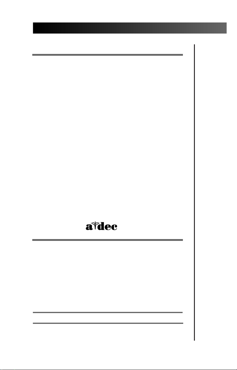
Assistant’s instrumentation typically includes
A-dec’s Autoclavable Syringe, Autoclavable HVE,
and Autoclavable Saliva Ejector as standard
equipment. On some units and carts, optional
instruments may include an additional HVE. The
Solids Collector (see Figures 3 and 4 on page 7) is also
a part of the Assistant’s Instrumentation, but its
location varies depending on your system.
2
Assistant’s Instrumentation
About Your Assistant’s Instrumentation
Figure 1. Assistant’s Instrumentation
(Shown with optional four position unitized holder
and additional Autoclavable HVE)
ADDITIONAL
AUTOCLAVABLE
QD HVE (optional)
AUTOCLAVABLE
SYRINGE
AUTOCLAVABLE
SALIVA EJECTOR
AUTOCLAVABLE
QD HVE
275¡F
136¡C
Page 7

The location of the master on/off toggle for
assistant’s instrumentation will vary but the
function is the same. Moving the toggle to the
ON position provides air and water to the system.
Move the toggle to the OFF position while the
unit is unattended to prevent water damage in
case of a leak.
Where assistant’s instrumentation is installed as
part of a delivery system (such as a chair mount
system, duo cart, duo Preference unit, or duo wall
mount unit), the master on/off toggle is located
on the control head. Other types of assistant’s
instrumentation may have the master on/off
toggle located on the post box .
When the instrumentation is installed on an
assistant’s cart or assistant’s wall mount unit, the
master on/off toggle is located on the side of the
cart or wall mount unit.
The master on/off toggle for chair-mounted
assistant’s instrumentation is located on the side
of the floor box .
3
Assistant’s Instrumentation
Controls
Page 8

Assistant’s instrumentation includes an A-dec
Autoclavable HVE and an Autoclavable Saliva
Ejector. It may also include a second HVE as an
option. The autoclavable HVE and Saliva Ejector
are equipped with a quick disconnect to remove
the valve body from the tubing for cleaning and
autoclaving.
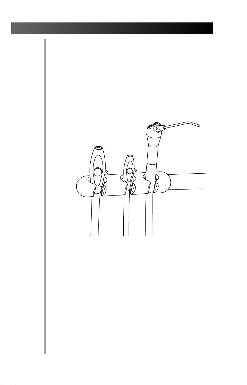
The HVE and Saliva Ejector can be easily converted
for opposite-hand operation (see Figure 2).
To convert the HVE or Saliva Ejector for oppositehand use, press the control valve out of the HVE
body (see Figure 2). Rotate the control valve 180°,
then press it back into place.
4
Assistant’s Instrumentation
Instruments
Autoclavable HVE and Saliva Ejector
Right- to Left-Hand Conversion of the Autoclavable HVE
and Saliva Ejector
Figure 2.
CONTROL
VALVE
VALVE
BODY
TO REMOVE THE
CONTROL VALVE,
PRESS ON SMALL
DIAMETER SIDE
HVE
SALIVA
EJECTOR
Page 9

1. Remove the tip from the valve body. (For
recommended HVE tip asepsis, see Sterilizing the
HVE Tip on page 6).
2. Although it is not necessary to do so, you may
want to turn off the central vacuum before
disconnecting the HVE or Saliva Ejector.
3. To remove the HVE or saliva ejector body, simply
separate the body from the tubing by pulling it
apart at the tailpiece (see Figure 2).
4. Remove the control valve by pressing it out of
the HVE or saliva ejector valve body.
5. Clean and rinse the valve body and control
valve using a mild detergent, water, the
brushes that have been provided, and allow
to dry completely.
6. Heat sterilize the valve body and control valve
using any of the following methods:
steam autoclave, dry heat, or chemical vapor.
7. Apply a light coat of A-dec Silicone Lubricant
(Part No. 98.0090.01, package of six) on the
O-ring seals of the control valve.
8. Reinstall the control valve in the valve body.
(see Figure 2).
9. Reinstall the body on the tubing tailpiece.
10. Operate the HVE and the saliva ejector valves
several times to verify that it rotates smoothly.
5
Assistant’s Instrumentation
Autoclavable HVE and Saliva Ejector Asepsis
Caution
Use only silicone lubricant when lubricating
instrumentation O-rings. Petroleum products will
cause permanent damage to the O-rings.
Page 10

Sterilizing the HVE Tip
It is recommended that the A-dec stainless steel
tips used on the A-dec HVE be heat sterilized
between patients by any of the following methods:
steam autoclave, dry heat, or chemical vapor.
1. Remove the HVE tip from the HVE valve body.
2. Clean and rinse the HVE tips using a mild detergent
and water, then allow the tips to completely dry.
3. Sterilize the HVE tips using one of the methods
listed above.
If you are using disposable HVE tips, be sure to
replace them with new tips between patients.
For information on the operation, care, and
maintenance of A-dec’s Autoclavable Syringe, refer to
your Autoclavable Syringe Owner’s Guide(A-dec
Publication No. 85.0680.00).
6
Assistant’s Instrumentation
Autoclavable Syringe
Note
The standard A-dec HVE is designed with a
cannula connection opening of 0.435 ± 0.006 inch
(11.05 ± 0.15 mm). Please select tips compatible
with this if not using A-dec tips.
Note
The A-dec 15 mm HVE has a cannula connection
opening of .592 inch (14.8 mm) + 1 1/2˚ per side per
DIN-13-938 section 3.1. Please select tips compatible
with this.
Note
The A-dec Saliva Ejector is designed with a cannula
connection opening of 0.265 ± 0.006 inch (6.73 ±
0.15 mm). Please select tips compatible with this.
Page 11

The solids collector prevents solids from entering
the central vacuum system (see Figures 3 and 4).
7
Assistant’s Instrumentation
Solids Collector
Figure 3. Cascade and Radius Solids Collector
Figure 4. Decade Cart Solids Collector
DECADE
CART SOLIDS
COLLECTOR
CANISTER
ASSEMBLY
SOLIDS
COLLECTOR
4
4
3
3
50
50
60
60
5
5
40
40
2
2
70
70
30
30
80
80
20
20
6
6
1
1
90
90
10
10
100
100
0
0
psi
psi
7
7
0
0
2
2
kg/cm
kg/cm
AW
Page 12

At least once per week, remove and clean (with a
mild detergent and water) or discard and replace the
solids collector screen for the Cascade products (see
Figure 5) or for the Decade products (see Figure 6). This
is necessary to ensure proper suction from the central
vacuum, and to maintain proper treatment room
asepsis.
Solids Collector for Cascade
Turn OFF vacuum or, if vacuum is ON, open the
HVE control valve to facilitate removal of the solids
collector cap.
Remove the solids collector screen and cap from the
connector. Pull out on the cap: the screen is
attached to the cap.
Remove the screen from the cap. Place your thumb
on the large hole and forefinger on the key directly
opposite the large hole (see Figure 5). Squeeze, then
slide the cap out of the screen. Clean the screen. If
you have a disposable HVE screen, discard following
the manufacturer’s instructions.
8
Assistant’s Instrumentation
Solids Collector Asepsis
Caution
Do not empty the screen into your cuspidor.
Doing so could plug the drain.
Page 13

Reinstall the solids collector. Insert the cap back
into the screen until the two circular buttons on
the cap snap into place. Make sure they are
properly aligned with the tongue on the cap
directly opposite to the large hole in the screen
(see Figure 5). Slide the screen and cap into the
vacuum connector, making sure the key faces up
and the hole faces down.
Solids Collector for Decade
Turn OFF the vacuum in order to remove the solids
collector cap. However, if vacuum is ON, open the
HVE to facilitate removal of the solids collector cap
(see Figure 6). Clean the screen. DO NOT lubricate
the O-rings on the vacuum canister cap.
9
Assistant’s Instrumentation
Figure 5. Solids Collector for Cascade
HVE
HANDPIECE
TUBING
SOLIDS
COLLECTOR
CAP
SOLIDS
COLLECTOR
SCREEN
VACUUM
CONNECTOR
KEY
(align for
reinstallation)
LARGE HOLE
(underneath, align
for reinstallation)
Figure 6. Solids Collector for Decade
CAP
SCREEN
CANISTER
Page 14

The multi-position style instrument holder is
designed to pivot or twist to provide flexibility in
positioning the instruments to suit your style of
practice. Pivot and twist tension are set at the
factory and should not need to be adjusted. If the
pivot or twist movement is too tight or too loose,
you may want to adjust the friction.
Pivot Friction
To adjust the pivot friction, locate the adjustment
setscrew (see Figure 7). Use a 5/32-inch hex key and
turn the key clockwise to increase friction which
will make the holder pivot less freely. Turn the key
counterclockwise to decrease friction and allow the
holder to pivot more freely.
Twist Friction
To adjust the twist friction, locate the adjustment
setscrew (see Figure 7). Use a 3/32-inch hex key and
turn the key clockwise to increase friction which
will make the holder twist less freely. Turn the key
counterclockwise to decrease friction and allow the
holder to twist more freely.
10
Assistant’s Instrumentation
Adjustments
Instrument Holder Positioning
Figure 7. Pivot and Twist Adjustments
TWIST ADJUSTMENT
SCREW (Underneath)
PIVOT ADJUSTMENT
SCREW (Underneath)
Page 15

If you have a telescoping assistant’s instrumentation
arm, it has been leveled at the factory and should not
require further adjustment. However, if the arm needs
to be leveled, locate the adjustment setscrew
underneath the telescoping arm (see Figure 8).
To tilt the arm up, use a 1/8-inch hex key and
turn the key clockwise.
To tilt the arm down, use a 1/8-inch hex key and
turn the key counterclockwise.
11
Assistant’s Instrumentation
Leveling Adjustment
Figure 8. Leveling Adjustment
LEVELING
ADJUSTMENT
SETSCREW
(underneath)
PIVOT ARM
TELESCOPING
ARM
Page 16

For chair touch pad instructions, refer to the
Cascade 1040 Chair Owner's Guide, A-dec
Publication No. 85.2605.00 or Decade 1011/1021
Chair Owner's Guide, A-dec Publication No.
85.2635.00 depending on your model of chair.
For Master touch pad instruction, refer to your
Master Series Touch Pad Owner’s Guide, A-dec
Publication No, 85.2627.00.
12
Assistant’s Instrumentation
Touch Pad Programming (optional)
Page 17

Autoclavable HVE and
Saliva Ejector .................................................. page 5
Sterilizing the HVE tip ...................................... page 6
Autoclavable Syringe
Owner’s Guide ..................................... 85.0680.00
Solids Collector Asepsis .................................... page 8
Floor Boxes
Owner’s Guide ..................................... 85.2611.00
Maintenance Parts
Owner’s Guide ..................................... 85.2634.00
Instrument Holder Positioning ....................... page 10
Pivot Friction ................................................... page 10
Twist Friction .................................................. page 10
Leveling Adjustment ...................................... page 11
Touch Pad Programming
Cascade 1040 Chair
Owner’s Guide ........................................85.2605.00
Decade 1011/1021 Chair
Owner’s Guide ........................................85.2635.00
Master Touch Pad
Owner’s Guide ........................................85.2627.00
Minimum air, water, and vacuum service
requirements for proper unit operation:
Air: 2.50 cfm (70.80 l/min) at 80 psi (551 kPa).
Water: 1.50 gpm (5.68 l/min) at 40 psi (276 kPa).
Vacuum: 12 cfm (339.84 l/min) at 8 inches (27 kPa)
of mercury.
Weight of optional touch pad: .50 lbs. (.23 kg).
Specifications are subject to change without notice.
13
Assistant’s Instrumentation
Maintenance
Adjustments and Specifications
Page 18

14
Assistant’s Instrumentation
Recognized by Underwriters Laboratories Inc. ® with respect to
electric shock, fire and mechanical hazards only in accordance
with UL 2601-1. Recognized with respect to electric shock, fire,
mechanical and other specified hazards only in accordance with
CAN/CSA C22.2, No. 601.1.
UL listed to US (UL 544) and Canadian (CAN/CSA C22.2, No.
125) safety standards.
Classified by Underwriters Laboratories Inc. ® with respect to
electric shock, fire and mechanical hazards only in accordance
with UL 2601-1. Classified with respect to electric shock, fire,
mechanical and other specified hazards only in accordance with
CAN/CSA C22.2, No. 601.1.
Conforms to European Directives
(refer to Declaration Statement)
Protective earth (ground).
Functional earth (ground).
Attention, consult accompanying documents.
TYPE B APPLIED PART.
CLASS II EQUIPMENT.
Type of shock protection:
CLASS I EQUIPMENT
(Dental Chairs, Dental Lights, & Power Supplies)
CLASS II EQUIPMENT
(Chair, Wall, & Cart Mounted Delivery Systems)
Degree of shock protection:
TYPE B APPLIED PART (All products)
Degree of protection against water ingress:
ORDINARY EQUIPMENT (All products)
Mode of operation
CONTINUOUS OPERATION
(All models except Dental Chairs)
Mode of operation
CONTINUOUS OPERATION
WITH INTERMITTENT LOADING (Dental Chairs)
Identification of Symbols
Classification of Equipment (EN 60601-1)
®
LISTED
!
Page 19

Page 20

Printed in USA.
Copyright © 1999,
All Rights Reserved.
Made with 50% waste paper
85.2610.00
1999-11 Rev L
(01649)
2601 Crestview Drive
Newberg, Oregon 97132 U.S.A.
Telephone 1-800-547-1883
(503) 538-7478
Fax (503) 538-0276
®
Designated Representative’s Address:
A-dec Dental U.K., Ltd.
Austin House
11 Liberty Way
Attleborough Fields,
Nuneaton, Warwickshire,
England CV11 6RZ
Telephone: 00 44 24 7635 0901
Fax: 00 44 24 7634 5106
Designated Representative’s Address:
A-dec Australia
41-43 Bowden Street
Alexandria, N.S.W. 2015, Australia
Telephone: (61) 1.800.225010
 Loading...