

Page 1

A-dec 311, 411, and 511 Dental Chairs Service Guide
Contents
Overview ......................................................................................................... 3
Copyright and Regulatory Information ................................................................. 3
Trademarks and Additional Intellectual Property Rights ....................................... 3
Product Service ........................................................................................................ 3
Regulatory Information ............................................................................................3
Product Models and Versions Covered in This Document .................................... 3
Customer Service Information............................................................................... 4
A-dec Headquarters ................................................................................................. 4
A-dec Australia ......................................................................................................... 4
A-dec China .............................................................................................................. 4
A-dec United Kingdom ............................................................................................. 4
Other Sources of Information ................................................................................ 4
A-dec 311, 411, and 511 Dental Chairs Service Reference ................................. 4
Other A-dec Service Documents ............................................................................. 4
Electronic Documentation ...................................................................................... 4
A-dec Dental Chairs ................................................................................................ 5
Chair Comparison Chart ......................................................................................... 6
Flow Diagrams ............................................................................................... 8
311 (A) Chair Flow Diagram (Before March 2013) .............................................. 8
311 (A) [Effective March 2013]/311 (B)/411 Chair Flow Diagram ................... 9
511 Chair Flow Diagram ...................................................................................... 10
Circuit Board Components ......................................................................... 12
311 (A and B)/411 Chair Circuit Board .............................................................. 12
311 (A and B)/411 Chair Circuit Board LED Identication .................................13
311 (A and B)/411 Chair Circuit Board Identication .........................................13
511 Chair Circuit Board ....................................................................................... 14
511 Chair Circuit Board LED Identication ..........................................................15
511 Chair Circuit Board Identication ..................................................................15
311 (A) Chair Service, Adjustments, and Maintenance ...........................16
Chair Covers [311 (A)] ..........................................................................................16
Integrated Floor Box Cover Removal ....................................................................16
Contoured Floor Box Cover Set Removal ............................................................. 17
Lift Arm Covers Removal ....................................................................................... 17
Upholstery [311 (A)] .............................................................................................18
Back Upholstery Removal/Attachment ................................................................18
Headrest Upholstery Removal/Attachment .........................................................18
Seat Upholstery Removal/Attachment .................................................................18
Factory Default Routine [311 (A and B) and 411] .............................................19
Chair Drive System [311 (A)]................................................................................20
Chair Manifold Adjustment System [311 (A)] ......................................................20
Hydraulic Fluid Replenishment [311 (A)] ............................................................. 21
Capacitor Replacement [311 (A and B)/411] ....................................................22
Chair Input Voltages ..............................................................................................22
Motor Driven Electro-Mechanical Actuator [311 (A and B)/411] ....................23
Position Sensor [311 (A and B)/411] .................................................................23
Factory Default Routine ........................................................................................23
Limp Along Feature................................................................................................23
Solenoid [311 (A)] ................................................................................................. 24
Solenoid Testing ....................................................................................................24
Magnetic Pull Test for Coil Resistance ................................................................. 24
Volt/Ohm Meter Test for Coil Resistance ............................................................. 24
Solenoid Assembly Replacement [311 (A)] .........................................................25
Headrest Adjustments [311 (A)] ..........................................................................26
Patient-Adjustable Neck Support Removal/Attachment ....................................26
Reposition Neck Support ......................................................................................26
Dual-Articulating Headrest [311 (A and B)/411] .............................................. 26
Headrest Adjustment ............................................................................................26
Glide Bar Tension Adjustment ..............................................................................26
Two-Position Armrest Adjustments [311 (A)] ..................................................... 27
Armrests Repositioning ......................................................................................... 27
Armrests Locking ................................................................................................... 27
86.0380.00 Rev B Contents 1
Page 2

A-dec 311, 411, and 511 Dental Chairs Service Guide Contents 2
311 (B) and 411 Chairs Service, Adjustments, and Maintenance ........ 28
Chair Covers ......................................................................................................... 28
Upholstery [311 (B) and 411] .............................................................................. 29
Back Upholstery Removal/Attachment ................................................................29
Headrest Upholstery Removal/Attachment .........................................................29
Seat Upholstery Removal/Attachment .................................................................29
Chair Drive System [311 (B) and 411] ................................................................30
Hydraulic System [311 (B) and 411] .................................................................... 31
Hydraulic Fluid Reservoir Replenishment [311 (B) and 411] ............................. 31
Factory Default Routine [311 (A and B) and 411] .............................................32
Capacitor Replacement [311 (B)/411] ..............................................................33
Chair Input Voltages ..............................................................................................33
Motor Driven Electro-Mechanical Actuator [311 (B) and 411] .........................34
Position Sensor [311 (A and B)/411] .................................................................35
Factory Default Routine ........................................................................................35
Limp Along Feature................................................................................................35
Solenoid [311 (B) and 411] .................................................................................36
Solenoid Testing ....................................................................................................36
Magnetic Pull Test for Coil Resistance .................................................................36
Volt/Ohm Meter Test for Coil Resistance .............................................................36
Solenoid Assembly Replacement [311 (B) and 411] .......................................... 37
Chair Stop Plate [311 (B) and 411] .....................................................................38
Stop Switch ............................................................................................................38
Chair Bump-Up Feature [311 (B) and 411] ..........................................................38
Dual-Articulating Headrest [311 (A)/311 (B)/411] ........................................... 39
Headrest Adjustment ............................................................................................39
Glide Bar Tension Adjustment ..............................................................................39
Armrest Adjustments [311 (B) and 411] ............................................................40
Two-Position Armrests Adjustment .......................................................................40
Arm Rest Rotation Tension Adjustment ................................................................40
Swivel Brake Adjustment [311 (B) and 411] ...................................................... 41
Swivel Brake........................................................................................................... 41
Swivel Brake Tension Adjustment ........................................................................ 41
Factory Default Routine (511) .............................................................................44
Chair Drive System (511) ..................................................................................... 45
Hydraulic Cylinders ............................................................................................... 45
Motor Driven Hydraulic Pump ..............................................................................45
Hydraulic System (511) .........................................................................................46
Hydraulic Fluid Reservoir Replenishment (511) ..................................................46
Capacitor (511) ..................................................................................................... 47
Solenoid (511) ......................................................................................................48
Solenoid Testing ...................................................................................................48
Magnetic Pull Test for Coil Resistance .................................................................48
Volt/Ohm Meter Test for Coil Resistance .............................................................48
Solenoid Assembly Replacement (511) ...............................................................49
Position Sensors (511) .........................................................................................50
Chair Stop Plate (511) .......................................................................................... 51
Stop Switch ............................................................................................................ 51
Chair Bump-Up Feature (511) ............................................................................... 51
Headrest Adjustment (511) ................................................................................. 52
Swivel Brake Adjustment (511) ...........................................................................53
Swivel Brake Operation .........................................................................................53
Swivel Brake Tension Adjustment ........................................................................53
Chair Programming .................................................................................... 54
Overview ................................................................................................................ 54
Chair Positioning ..................................................................................................55
Chair Direction Buttons .........................................................................................55
Programmable Chair Buttons/Factory Presets ....................................................55
Customize the X-Ray/Rinse Button ......................................................................55
Troubleshooting .......................................................................................... 56
Overview ................................................................................................................ 56
A-dec 311 (A and B) and 411 Dental Chairs Troubleshooting ..........................56
A-dec 511 Dental Chairs Troubleshooting .......................................................... 59
Chair Circuit Board Diagnostics .......................................................................... 63
511 Chair Service, Adjustments, and Maintenance ............................... 42
Chair Covers (511) ................................................................................................ 42
Upholstery (511) ................................................................................................... 43
Back Upholstery Removal/Attachment ................................................................43
Headrest Upholstery Removal/Attachment .........................................................43
Seat Upholstery Removal/Attachment .................................................................43
Page 3

Overview
Copyright and Regulatory Information
Copyright
© 2015 A-dec Inc. All rights reserved.
A-dec Inc. makes no warranty of any kind with regard to this material,
including, but not limited to, the implied warranties of merchantability
and fitness for a particular purpose. A-dec Inc. shall not be held liable
for any errors contained herein or any consequential or other damages
concerning the furnishing, performance or use of this material. The
information in this document is subject to change without notice. If you
find any problems in the documentation, please report them to us in
writing. A-dec Inc. does not warrant that this document is error-free.
No part of this document may be copied, reproduced, altered, or
transmitted in any form or by any means, electronic or mechanical,
including photocopying, recording, or by any information storage and
retrieval system, without prior written permission from A-dec Inc.
Trademarks and Additional Intellectual Property Rights
A-dec, the A-dec logo, A-dec 500, A-dec 300, Cascade, Cascade Master
Series, Century Plus, Continental, Decade, ICX, ICV, Performer,
Preference, Preference Collection, Preference ICC, and Radius are
trademarks of A-dec Inc. and are registered in the United States and
other countries. A-dec 400, A-dec 200, Inspire, Preference Slimline, and
reliablecreativesolutions are also trademarks of A-dec Inc. None of
the trademarks or trade names in this document may be reproduced,
copied, or manipulated in any manner without the express, written
approval of the trademark owner.
Product Service
For product service information, please contact your local authorized
A-dec dealer. To find your local dealer, visit www.a-dec.com.
Regulatory Information
Warranty information is provided in the Regulatory Information,
Specifications, and Warranty document (p/n 86.0221.00), which is
available in the Document Library at www.a-dec.com. This document
includes:
• Serial number identification
• Software revisions
• Deluxe touchpad help messages
• Intended application and use statements
• Identification of symbols
• Environmental specifications
• Classification of equipment
• Electrical rating and electromagnetic information
• Chair load capacity
Product Models and Versions Covered in This Document
A-dec uses product versions to indicate significant changes to a product
model. Modifications identified by a change to the product version
include, but are not limited to, significant changes to features and
options, and product compatibility.
Certain touchpad symbols are proprietary to A-dec Inc. Any use of
these symbols, in whole or in part, without the express written consent
of A-dec Inc., is strictly prohibited.
86.0380.00 Rev B Overview 3
Models Versions Description
311 A, B Dental Chairs
411 A Dental Chairs
511 A Dental Chairs
Page 4

A-dec 311, 411, and 511 Dental Chairs Service Guide Overview 4
Customer Service Information
For questions not addressed in this document, contact A-dec Customer
Service using contact information for your region.
A-dec Headquarters
2601 Crestview Drive
Newberg, Oregon 97132
United States
Tel: 1.800.547.1883 within USA/CAN
Tel: +1.503.538.7478 outside USA/CAN
Fax: 1.503.538.0276
www.a-dec.com
A-dec Australia
Unit 8
5-9 Ricketty Street
Mascot, NSW 2020
Australia
Tel: 1.800.225.010 within AUS
Tel: +61.(0).2.8332.4000 outside AUS
A-dec China
A-dec (Hangzhou) Dental Equipment Co., Ltd.
528 Shunfeng Road
Qianjiang Economic Development Zone
Hangzhou 311106
Zheijiang, China
Tel: +1.503.538.7478
A-dec United Kingdom
EU Authorized Representative
Austin House, 11 Liberty Way
Nuneaton, Warwickshire CV11 6RZ
England
Tel: 0800.ADEC.UK (2332.85) within UK
Tel: +44.(0).24.7635.0901 outside UK
Tel: +44 (0) 24 7635 0901 outside UK
www.a-dec.co.uk
Web Contact
Partner Resources websites: www.a-dec.biz.
Other Sources of Information
A-dec 311, 411, and 511 Dental Chairs Service Reference
The A-dec 311, 411, and 511 Dental Chairs Service Guide is a companion
to the A-dec 311, 411, and 511 Dental Chairs Service Reference (p/n
86.0381.00). The service reference contains illustrated parts breakdown
content. Circuit board components and flow diagrams are in both
documents.
Other A-dec Service Documents
The A-dec 300, 400, and 500 Delivery Systems Service Guide (p/n
86.0382.00) contains service, maintenance, and troubleshooting
content. The A-dec 300, 400, and 500 Delivery Systems Service Reference
(p/n 86.0383.00) contains illustrated parts breakdown content. Circuit
board components and flow diagrams are in both documents. These
documents include cuspidors, floor boxes, and support centers.
The A-dec Dental Lights and Monitor Mounts Service Guide (p/n
86.0326.00) contains service, maintenance, and troubleshooting content
for A-dec dental lights and monitor mounts. The A-dec Dental Lights and
Monitor Mounts Service Reference (p/n 86.0328.00) contains illustrated
parts breakdown content. Circuit board components and flow diagrams
are in both documents.
Genuine A-dec Parts Catalog
The Genuine A-dec Service Parts Catalog, p/n 85.5000.00, provides part
number and ordering information for A-dec serviceable parts. This
catalog details service parts for current products and products which
are no longer manufactured but are still supported. Refer to this catalog
for additional details on parts found in the service guide.
Electronic Documentation
The latest versions of A-dec documents are available as electronic
documents on the A-dec website (www.a-dec.com). On the website,
select Document Library in the upper-right corner of the page. Check
this location for the most current technical information about A-dec
products.
Page 5
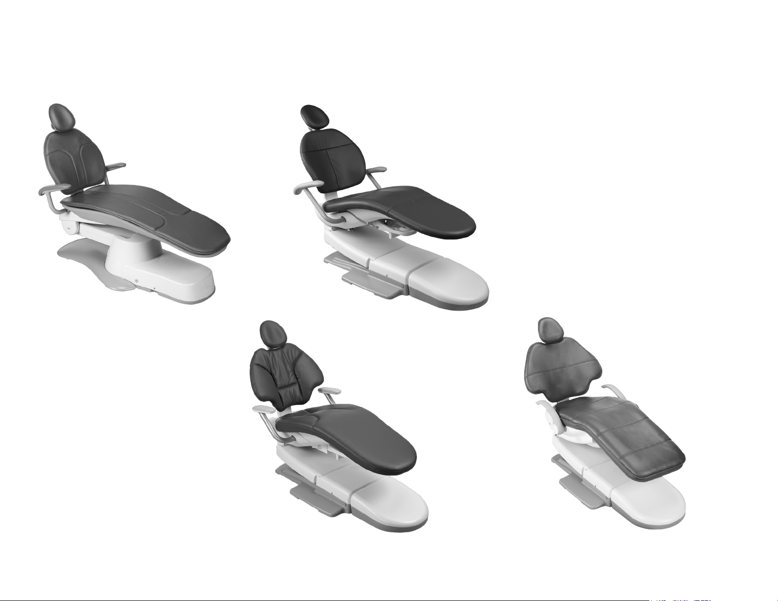
A-dec Dental Chairs
A-dec 311 (Version A) Dental Chair
An optional contoured floor box is also available.
A-dec 311 (Version B) Dental Chair
A-dec 411 Dental Chair
A-dec 511 Dental Chair
86.0380.00 Rev B Overview 5
Page 6
A-dec 311, 411, and 511 Dental Chairs Service Guide Overview 6
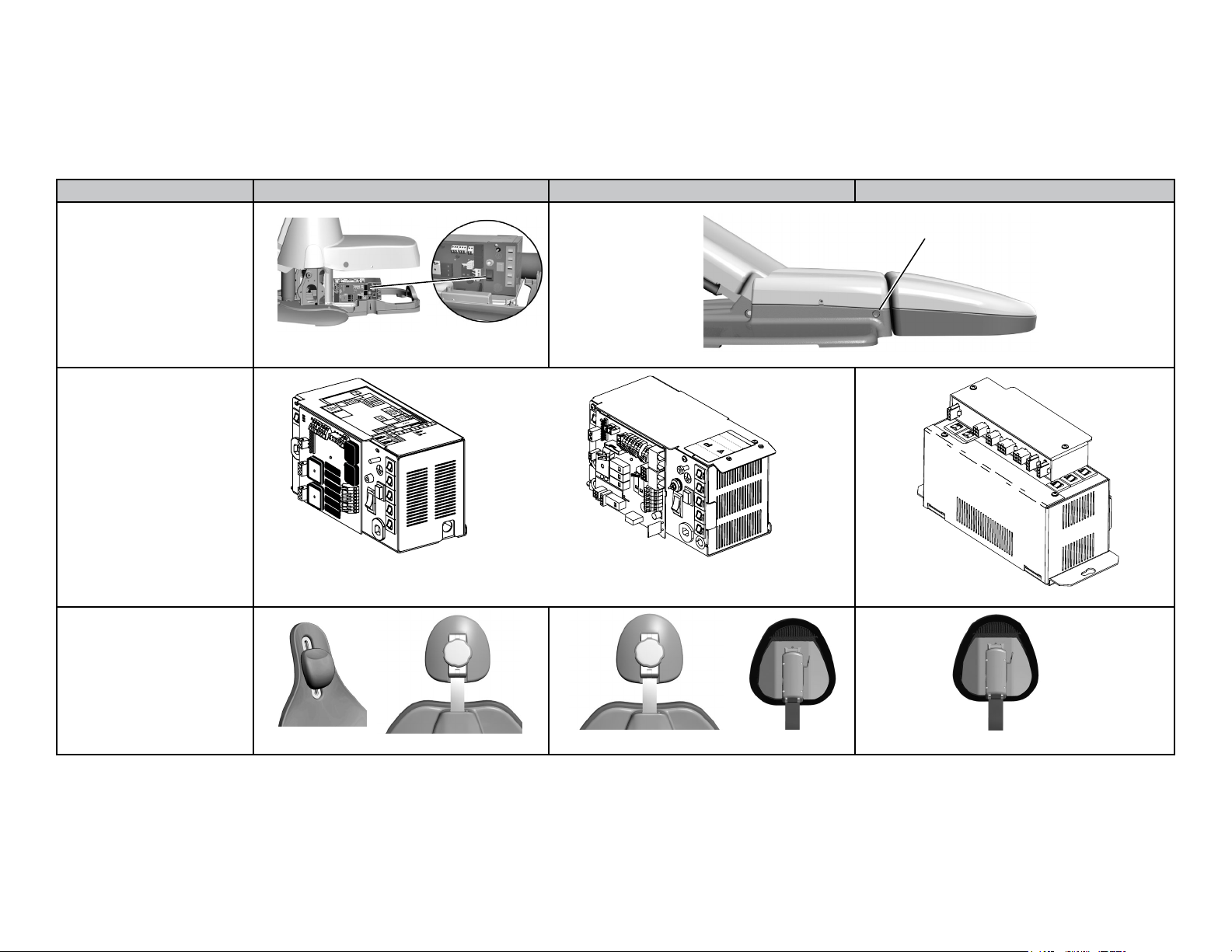
Chair Comparison Chart
A-dec 311 (Version A) Chair A-dec 411/311 (Version B) Chair A-dec 511 Chair
On/Off Button Location
Power On/Off
Power Supplies
Dual Articulating Headrests/
Neck Support
311 Power Supply
(Before March 2013)
Neck Support
Locking Knob
311 (A and B) /411 Power Supply
(Effective March 2013)
Locking Knob
Lever Release
Lever Release
Page 7
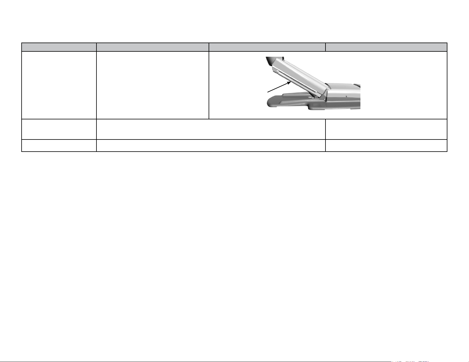
A-dec 311 (Version A) Chair A-dec 411/311 (Version B) Chair A-dec 511 Chair
Stop Switch Location (not applicable)
Stop Switch
Chair Drive System Hydraulic Base
Electrical Back
Armrests Two-Position Armrest Multi-Position Armrest
Hydraulic Base
Hydraulic Back
86.0380.00 Rev B Overview 7
Page 8
A-dec 311, 411, and 511 Dental Chairs Service Guide Flow Diagrams 8
Flow Diagrams
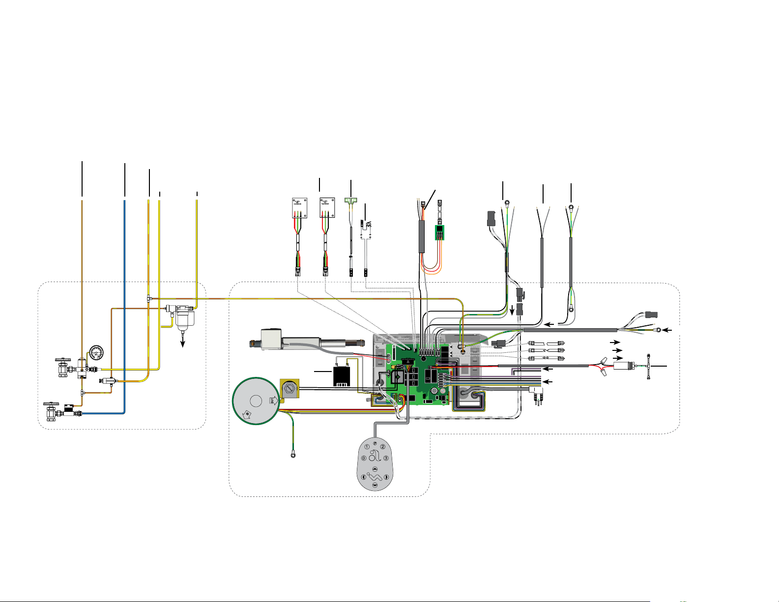
311 (A) Chair Flow Diagram (Before March 2013)
Utilities
To Control Head
Master Toggle
To Water Manifold/
Cuspidor
From Control Head
To Control Head and
Foot Control
(Optional
Moisture
Separator)
To Drain
Chair
Hydraulic
Pump
Base Position Sensor
Back Position Sensor
Solenoid
Linear
Actuator
Power Supply
Capacitor
To Support Center
Power Supply (Top
View)
From 371 Dental
Light or 571-300
Dental Light
Footswitch
Page 9
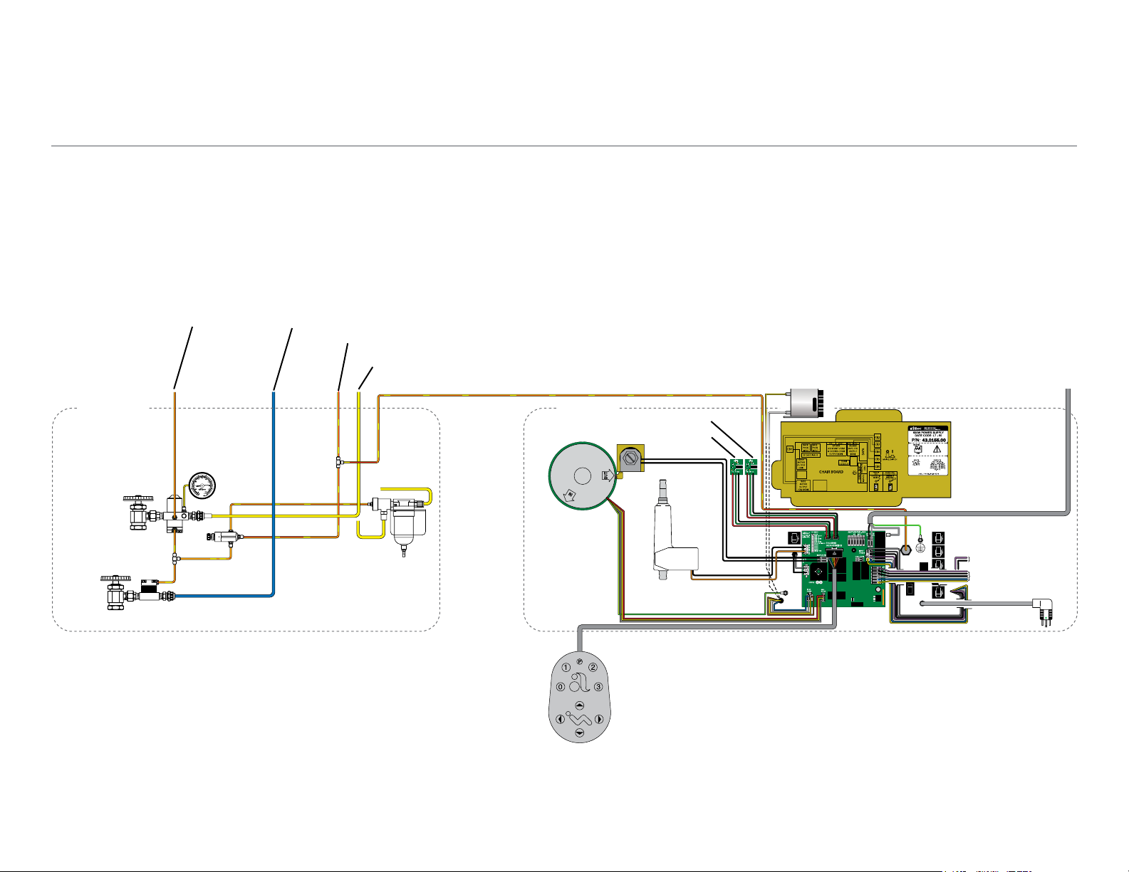
311 (A) [Effective March 2013]/311 (B)/411 Chair Flow Diagram
To Control Head
Master Toggle
To Water Manifold/
Cuspidor
From Control Head
To Control Head and
Foot Control
To Drain
(Optional Moisture
Separator)
Utilities
From Control Head (optional
moisture separator)
Back Tilt Motor
Power Supply
Capacitor
Solenoid
Hydraulic
Pump
Position Sensors
(Back) (Base)
Back Limit Switch (411 Only)
From LED Light
Base Limit Switch (311 (B) and 411 Only)
43.0363.00
Power Supply (Front View)
From Radius Delivery
From 551 Assistant’s Arm
To Chair Power Supply
371 Light
571-300 Light
Chair
From 461 Post Box
300 Delivery
551 Assistant’s
461 Post Box
To Chair Power Supply
361, 362, 363 Post Box
Chair Lockout Kit
Footswitch
86.0380.00 Rev B Flow Diagrams 9
Page 10
A-dec 311, 411, and 511 Dental Chairs Service Guide Flow Diagrams 10
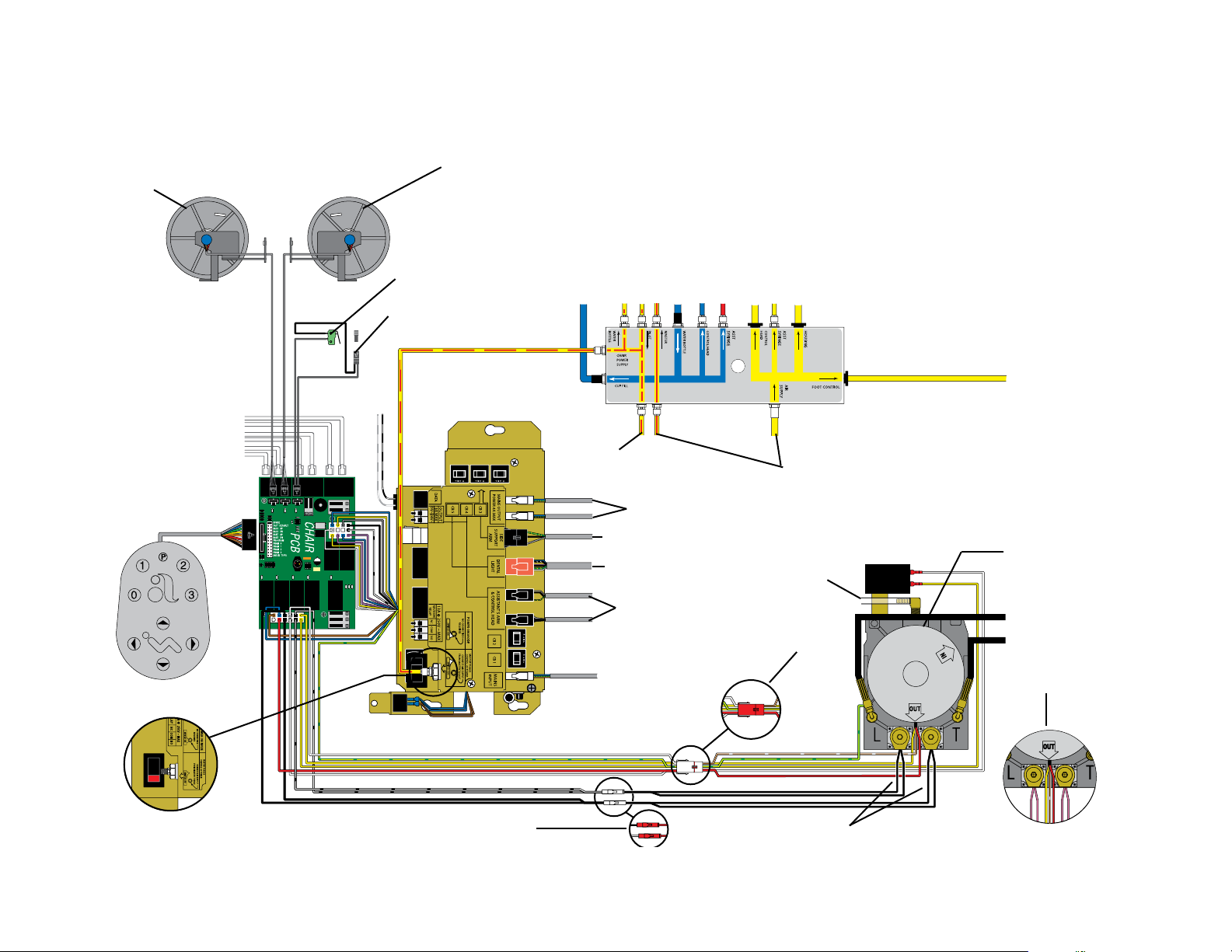
511 Chair Flow Diagram
Base Position
Sensor
Base Stop Switch
Lower Support Arm and
Link Limit Switch
Back Position
Sensor
To Water Bottle
To Cuspidor Cupfill
From Master Toggle
From Water bottle
To Master Toggle
To Control Block
To Flush Valve and Doctor's Syringe
To Assistant’s Syringe
To Assistant’s Syringe
To Amalgam Separator
To Data as Required
Footswitch
(Switch without Tubing)
To Delivery
System
Power Supply
240 V Connector
To Pre-Regulator
To Line volt Accessory
To Support Center
To Dental Light
To Control Head
or Assistant’s
Touchpad
From Mains
Manifolds
From Regulator
From
Reservoir
240 V Connector
Capacitor
To Foot Control
120 V - Hydraulic Pump
To Lift Cylinder
To Tilt Cylinder
240 V - Hydraulic Pump
(Pink Wires)Black and White Wires
Page 11

86.0380.00 Rev B Flow Diagrams 11
Page 12
A-dec 311, 411, and 511 Dental Chairs Service Guide Circuit Board Components 12
BACK
BASE
43.0363.00
16
5
25
26
27
Circuit Board Components
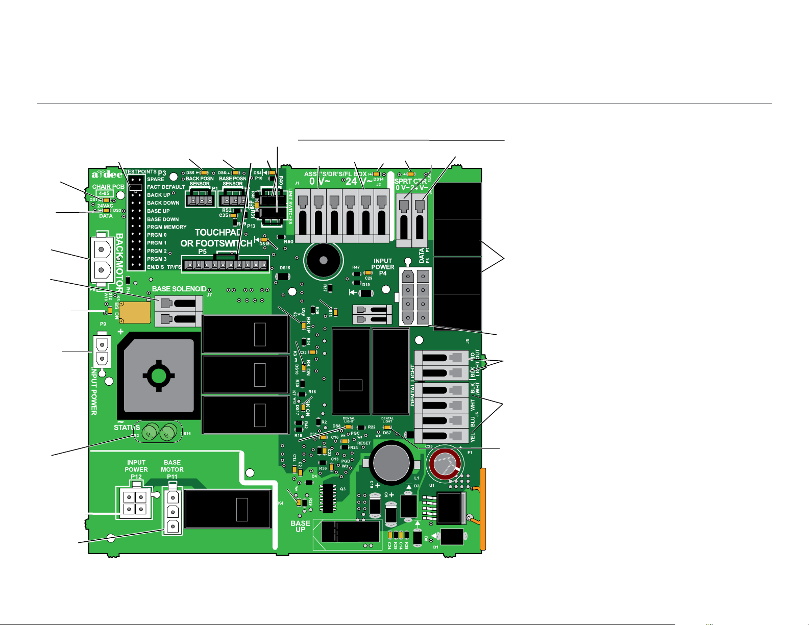
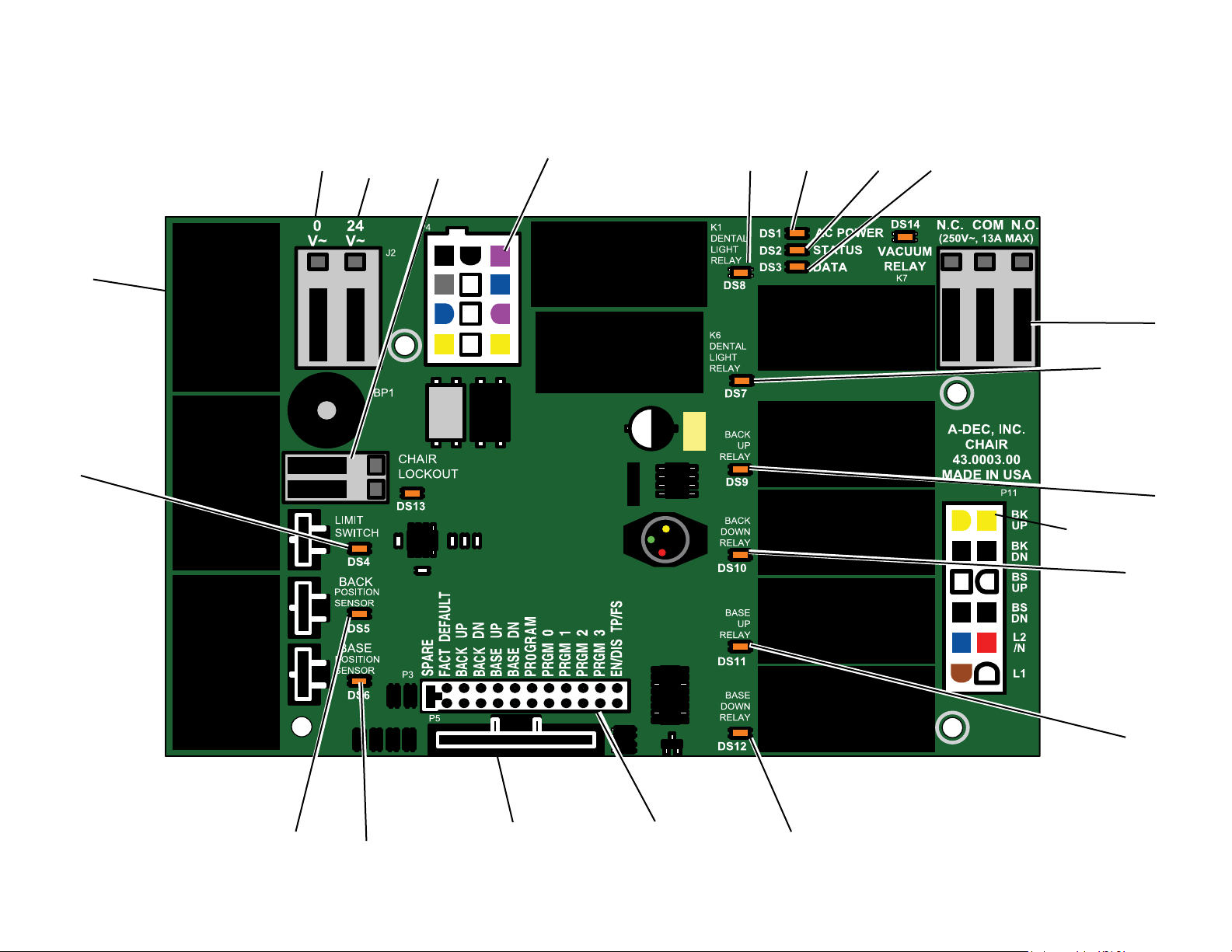
311 (A and B)/411 Chair Circuit Board
20
30
21
31 32
4
1
3
11
18
33
24
34
8
12
9
15
13
14
P13 and DS4:
• 311 (A): Effective July 2013: Jumpers are required on P10 and
P13 for the 311 (A) chair.
• 311 (B): Jumpers are required on P13 only.
• 411: No jumpers required. 411 has a base and a back limit switch.
19
17
28
29
7
2
10
23
22
6
Page 13
311 (A and B)/411 Chair Circuit Board LED Identification
311 (A and B)/411 Chair Circuit Board Identification
LED Status Description
DS1, DS14, and
DS15 - AC power
LED
DS2 and DS16Status LED
DS3 - Data LED Off No DCS communication, not connected to
DS13 - Chair lockout Off Open, (normal)
DS5, DS6 - Chair
position sensors
DS9, DS10, DS11,
DS12, DS17- Chair
relay LEDs
DS7, DS8 - Dental
light relay LEDs
Off No 24 VAC power, tripped circuit breaker,
power supply turned off
Green, steady
Off System is not functioning, no power, or
Blue, steady
Blue, single blink
Blue, double blink
Green, steady
Green, blinking
Red, on
Off Position Sensor: not connected or bad
Yellow, steady
Yellow, fast blink
Yellow, slow blink
Off Relay is off
On Relay is on
Off Relay is off
On Relay is on
24 VAC present
circuit board has failed
Normal operation
Duty cycle limit of chair back has been
exceeded
Jumper is in factory mode
the DCS, or DCS has failed
Detects active DCS
Valid DCS Message
Closed, (activated)
connection; moving in wrong direction;
limited range of motion
Normal operation
Upper end of travel
Lower end of travel
CAUTION: Circuit boards are sensitive to static electricity.
Electrostatic Discharge (ESD) precautions are required when
touching a circuit board or making connections to or from the
circuit board. Circuit boards should be installed only by an
electrician or qualified service person.
Item Description Item Description
1 DS1 - AC power LED (CB1) 18 P5 - touchpad or footswitch connector
2 DS2, DS16 - status LEDs 19 P6/P7 - data ports
3 DS3 - data LED 20 P8 - back motor connector
4 DS5 - back position sensor, LED/
P1 Connector
5 DS6 - base position sensor LED/
P2 connector
6 DS7 - dental light LED/Relay K6 23 P12 - input power connector
7 DS8 - dental light LED/Relay K1 24 J1 - 0 VAC terminal strip (output) for
8 DS9 - back up LED/Relay K2 25 J2 - 24 VAC terminal strip (output) for
9 DS10 - back down LED/relay K3 26 J3 - 0 VAC terminal strip (output) for
10 DS11 - base up LED/relay K4 27 J3 - 24 VAC terminal strip (output) for
11 DS12 - base down LED/relay K5 28 J5 - dental light output terminal strip
12 DS13 - chair lockout LED/terminal
strip J4
13 DS14 - AC power LED (CB4) 30 J7 - base solenoid terminal strip
14 DS15 - AC power LED (CB5) 31 P10 - Jumper - 311 (A) chair only
15 DS17 - back on LED/Relay K7 32 P13 - Jumper - 311 (A and B) chairs
16 P3 - testpoints header 33 DS4 - Base stop switch
17 P4 - input power connector 34 DS 18 - Back stop switch
21 P9 - input power connector
22 P11 - base motor connector
Assistant’s, doctor’s, oor box
assistant’s, doctor’s and oor box
support center
support center
29 J6 - dental light input terminal strip
86.0380.00 Rev B Circuit Board Components 13
Page 14
A-dec 311, 411, and 511 Dental Chairs Service Guide Circuit Board Components 14
511 Chair Circuit Board
15
1
2
16
14
17
20
11
12
13
18
21
10
19
9
8
3
4
5
6
7
Page 15
511 Chair Circuit Board LED Identification
511 Chair Circuit Board Identification
LED Status Description
DS1 - AC power
LED
DS2 - Status LED Off System is not functioning, no power or circuit
DS3 - Data LED Off No DCS communication, not connected to the
DS4 - Chair limit
switch
DS13 - Chair
lockout
DS5 + DS6 Chair position
sensors
DS9, DS10,
DS11, DS12 Chair relay LEDs
DS7, DS8 Dental light relay
LEDs
DS14 - Vacuum
relay LED
Off No 24 VAC power, tripped circuit breaker, power
supply turned off, no line voltage
Green, steady
Green, steady
Green, steady
Green, blinking
Off Closed, (normal)
Red
Off Open, (normal)
Red
Off Position Sensor: Not connected or bad connection;
Yellow, steady
Yellow, fast blink
Yellow, slow blink
Off Relay is off
On Relay is on
Off Relay is off
On Relay is on
Off Relay is off
On Relay is on
24 VAC at the terminal strip
board has failed
Normal operation
DCS, or DCS has failed
Detects active DCS
Valid DCS message
Open, (activated)
Closed, (activated)
moving in wrong direction; limited range of motion;
or cable is not on the pully
Normal operation
Upper end of travel
Lower end of travel
Item Description Item Description
1 P7, P8, P9 - data ports 11 DS1 - AC power LED
2 DS4 - stop switch LED (limit
switch)/P10 connector
3 DS5 - back position sensor LED/
P1 connector
4 DS6 - base position sensor LED/
P2 connector
5 P5 - footswitch connector 15 J2 - 0 VAC terminal strip (output)
6 P3 - testpoints header 16 J2 - 24 VAC terminal strip (output)
7 DS12 - base down LED/relay K5 17 P4 - Input power/dental light
8 DS11 - base up LED/relay K4 18 J3 - vacuum relay K7 output terminal
9 DS10 - back down LED/relay K3 19 P11 - pump motor/solenoid
10 DS9 - back up LED/relay K2 20 DS8 - dental light LED relay/K1
12 DS2 - status LED
13 DS3 - data LED
14 DS13 - chair lockout LED/terminal
strip J1
connector
strip
connector
21 DS7 - dental light LED relay/K6
CAUTION: Circuit boards are sensitive to static electricity.
Electrostatic Discharge (ESD) precautions are required when
touching a circuit board or making connections to or from the
circuit board. Circuit boards should be installed only by an
electrician or qualified service person.
86.0380.00 Rev B Circuit Board Components 15
Page 16
A-dec 311, 411, and 511 Dental Chairs Service Guide 311 (A) Chair Service, Adjustments, and Maintenance 16
311 (A) Chair Service, Adjustments, and Maintenance
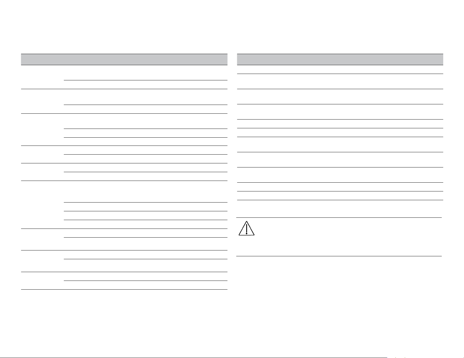
Chair Covers [311 (A)]
DANGER Failure to turn off the power before you begin this
procedure can lead to electrical shock.
WARNING Failure to turn off the power before you begin this
procedure can lead to product damage and result in serious
injury or death.
CAUTION When removing or replacing covers, take care not
to damage any wiring or tubing. Verify that the covers are
secure after replacing them.
Integrated Floor Box Cover Removal
To access the on/off button and power supply on chairs with an
integrated floor box cover, pull the utility cover out at the cover posts
and lift the cover off .
Cover
Post
Page 17
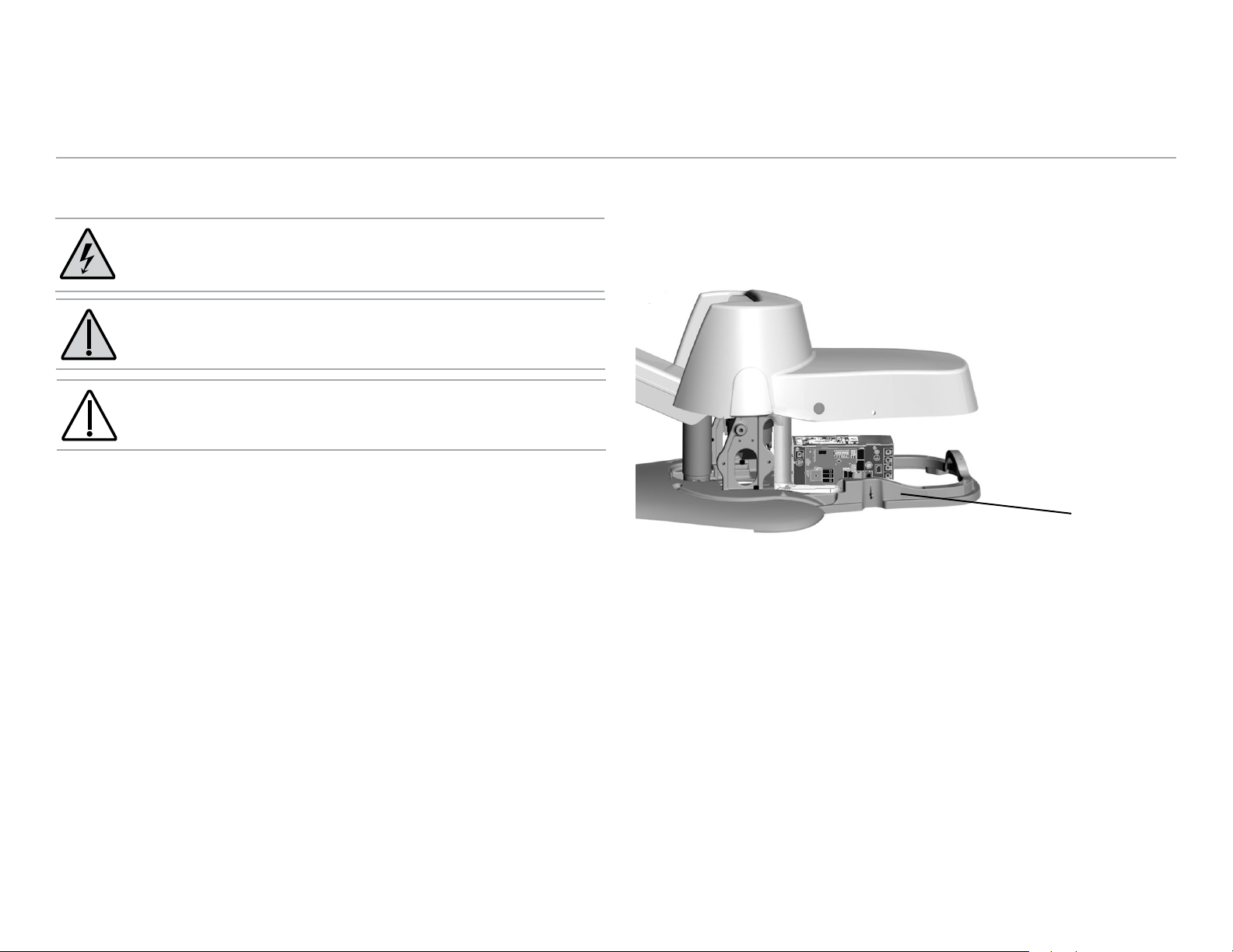
Contoured Floor Box Cover Set Removal
To access the on/off button and power supply on chairs with a
contoured floor box cover set, first remove the front floor box cover.
Grasp the cover on both sides and pull up. If needed, use a large coin in
the integrated coin slot to gently separate the contoured floor box cover
from the frame. Then remove the power supply cover.
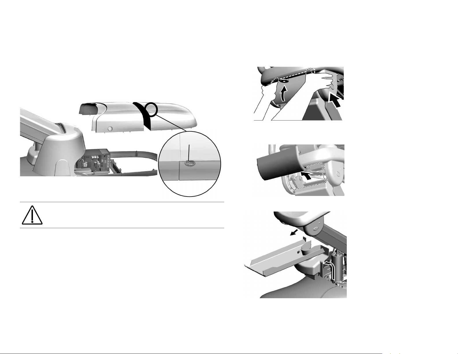
2. With your thumbs on the top of the upper lift arm cover, grasp
from the bottom and pull up and push in to disengage tabs from
slots.
3. Lift out the upper lift arm cover.
Coin Slot
CAUTION Take care not to damage the cover when using the
coin slot.
Lift Arm Covers Removal
If the utility cover is installed, remove it before beginning this
procedure.
1. Raise the chair base all the way up.
4. Remove the lift arm and lower lift arm cover.
86.0380.00 Rev B 311 (A) Chair Service, Adjustments, and Maintenance 17
Page 18
A-dec 311, 411, and 511 Dental Chairs Service Guide 311 (A) Chair Service, Adjustments, and Maintenance 18
Upholstery [311 (A)]
Back Upholstery Removal/Attachment
To remove the upholstery, firmly grasp the bottom edge of the armature
and lift up, then lift the upholstery away from the chair back support.
To reattach, place the key holes in the armature over the large fastener
heads, then push down until the upholstery inserts into position.
Remove
Headrest
Lift up, then
pull out
Fastener
Heads
Fastener
Heads
Headrest Upholstery Removal/Attachment
To remove the headrest upholstery, position the headrest to access the
two screws on the back, loosen the screws and remove the upholstery.
To reattach, position the headrest to access the screws, place the
upholstery on the headrest, insert and tighten the screws.
Lift up, then
pull out
Seat Upholstery Removal/Attachment
To remove the seat upholstery, pull the pins out on both sides of the
seat armature, then lift the seat and move it away.
CAUTION When replacing the upholstery, ensure the pins are
completely in place. The pin ring should be flush with the
seat armature.
Armature
Pin Ring
Mounting
Screws
Page 19
BACK
BASE
43.0363.00
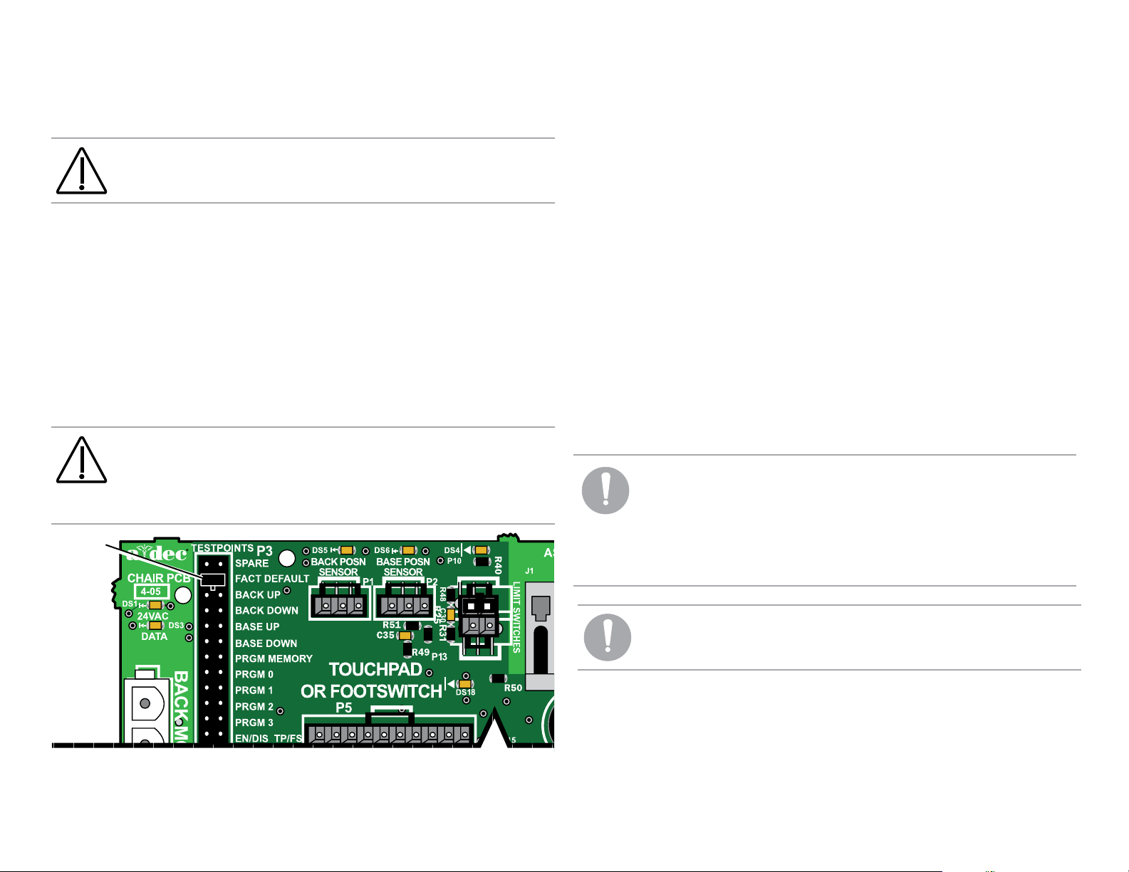
Factory Default Routine [311 (A and B) and 411]
CAUTION The position sensors can be inadvertently installed
upside down. Improper installation will limit the chair’s
functionality.
After installing a new chair, circuit board, or position sensor, run the
factory default routine. The routine:
• Sets the chair base and back upper limits
• Calculates new preset positions based on actual range of motion
of the chair
• Verifies that the position sensors work correctly
To start the factory default routine, place the spare jumper in the factory
default position on the P3 test points of the chair circuit board.
CAUTION Circuit boards are sensitive to static electricity.
Electrostatic Discharge (ESD) precautions are required when
touching a circuit board or making connections to or from
the circuit board. Circuit boards should be installed only by
an electrician or qualified service person.
Jumper in
Factory
Default
Position
When running the factory default routine, the chair:
1. Moves base down.
2. Moves base up.
3. Moves back down.
4. Moves back up.
5. Moves base and back to mid position.
6. Moves back and base down.
7. Moves base and back to mid position.
8. Moves base and back to Entry/Exit.
9. Three beeps confirm the routine completed successfully.
Once the routine completes, place the jumper into the Spare position
on P3.
NOTE The jumper must remain in the factory default
position to complete the factory default routine. The status
LEDs on the standard and deluxe touchpads and the chair
circuit board double blink while the factory default routine
is running and after the routine is complete. When the
routine is complete, three beeps sound. If the routine stops
prematurely, one beep sounds.
NOTE One beep indicates the routine failed to complete. See
page 56 for troubleshooting.
86.0380.00 Rev B 311 (A) Chair Service, Adjustments, and Maintenance 19
Page 20

A-dec 311, 411, and 511 Dental Chairs Service Guide 311 (A) Chair Service, Adjustments, and Maintenance 20
Chair Drive System [311 (A)]
The hydraulic chair system controls the base movement of the chair. An
electro-mechanical tilt actuator controls the back movement.
The chair seat has a vertical range of 13.75" (349 mm) to 29.5" (749 mm)
above the floor.
Chair Manifold Adjustment System [311 (A)]
Use a 3/32" hex key, to move the base down adjustment screw to
change the base down [chair] speed. Turning the screw clockwise
(tightening) decreases the base down speed. Turning the screw counterclockwise increases the base down speed.
Base Down
Hydraulic Motor
Pump Assembly
Adjustment Screw
Chair Manifold
Assembly
NOTE Do not over tighten the adjustment screw. If the screw
is too tight, the chair may not move.
Page 21
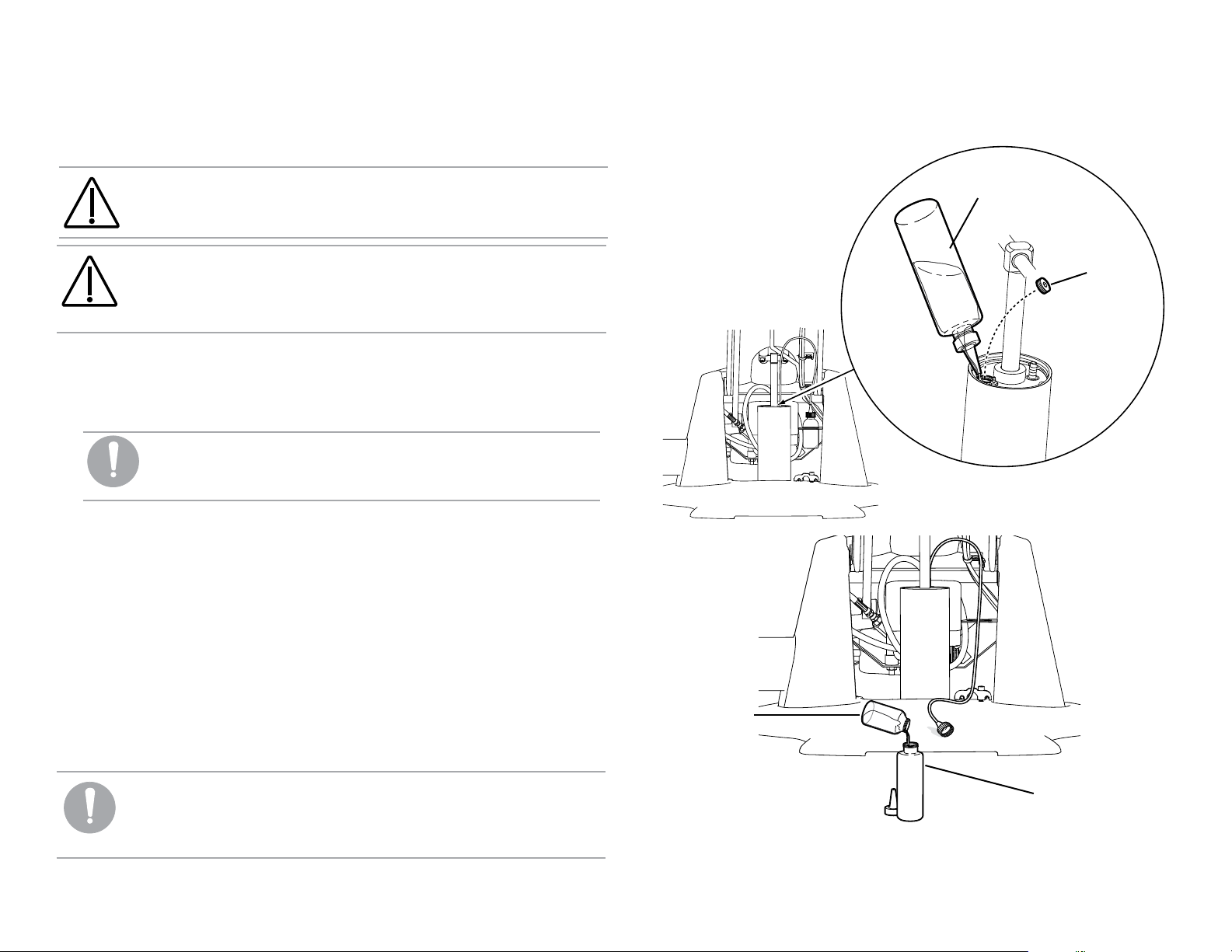
Hydraulic Fluid Replenishment [311 (A)]
Follow the steps below to add hydraulic fluid.
CAUTION Use only A-dec hydraulic fluid, p/n 61.0197.00.
Hydraulic Fluid
Bottle
CAUTION If the hydraulic cylinder needs to be replaced, or
if there has been a significant loss of hydraulic fluid, contact
A-dec Customer Service. The steps to replace the hydraulic
cylinder are complicated and specific.
1. Raise the chair to its highest level.
2. Use a 3/16" hex key to remove the fill plug from the top of the
hydraulic cylinder.
NOTE It may be difficult to measure exactly to the thread
level. You may want an absorbent towel available to
soak up some of the fluid if it seems too full.
3. Fill the hydraulic fluid to the plug thread level.
4. Replace the fill plug.
5. Lower the chair fully. The overflow bottle will capture any excess
fluid.
6. Raise the chair.
7. Remove the overflow bottle from the bracket.
8. Empty the overflow bottle.
9. Return the overflow bottle to the bracket.
Plug
Overflow Bottle
10. Run the factory default routine. (See page 19.)
NOTE Allow the chair to settle before operating. This allows
the air bubbles to separate from the oil. If you use the chair
Hydraulic Fluid
Bottle
and it makes noises, repeat steps 1 through 10 above.
86.0380.00 Rev B 311 (A) Chair Service, Adjustments, and Maintenance 21
Page 22

A-dec 311, 411, and 511 Dental Chairs Service Guide 311 (A) Chair Service, Adjustments, and Maintenance 22
Capacitor Replacement [311 (A and B)/411]
The hydraulic system used for the chair’s base movement is operated
using a motor capacitor, located in the power supply of the chair. There
are three specific capacitors for different line voltage ranges. The chair
motor capacitor can be replaced within the power supply.
DANGER Turn off the power to the system before you
continue with this procedure. Failure to do so can result in
electrical shock.
WARNING Turn off the power to the system before you
continue with this procedure. Failure to do so can result in
product damage, serious injury, and/or death.
Chair Input Voltages
Mains Chair Input Voltage A-dec Capacitor Part Number
100 VAC 90.1198.00
110 - 120 VAC 90.1199.00
220 - 240 VAC 90.1200.00
Before March 2013
Capacitor
Effective March 2013
Capacitor
Page 23

Motor Driven Electro-Mechanical Actuator [311 (A and B)/411]
The back-up and back-down movements are controlled with an electromechanical tilt actuator, which is located under the seat of the chair.
Back Position Sensor
Actuator
Base Position Sensor
A diagnostic LED is provided on the chair board for each position
sensor. Refer to Chair Circuit Board LED Identification, see page 12
for information. An additional LED, indicating power, is present on
each position sensor circuit board.
LED
Red
Green
Black
Black
Factory Default Routine
If a position sensor or chair board is replaced, run the factory default.
For instructions on running the factory default, see page 19.
Position Sensor [311 (A and B)/411]
The position sensor circuit boards provide positioning data to the chair
board. There is a position sensor for the back and a position sensor for
the base.
CAUTION The position sensors can be inadvertently installed
upside down. Improper installation will limit the chair’s
functionality.
Limp Along Feature
There are two position sensors, one for the base of the chair and one for
the back of the chair. If there is a problem or malfunction with a position
sensor, the limp along feature allows the operator to move the chair in
the up direction for one to three second intervals by pushing the manual
control buttons on the touchpad or footswitch. Refer to Chair Circuit
Board LED Identification on page 12 for further information. When in
limp along mode, presets will not function.
86.0380.00 Rev B 311 (A) Chair Service, Adjustments, and Maintenance 23
Page 24

A-dec 311, 411, and 511 Dental Chairs Service Guide 311 (A) Chair Service, Adjustments, and Maintenance 24
Solenoid [311 (A)]
p/n: 62.0317.00 21.6 VDC
Solenoid Testing
A solenoid is energized during base down function. To determine if
a solenoid has failed, check for coil resistance using magnetic pull or
volt/ohm meter test.
Magnetic Pull Test for Coil Resistance
1. Hold a paper clip loosely in your hand.
2. Activate the solenoid by pressing base down on the footswitch or
touchpad.
3. If there is a pull on the paper clip, the solenoid is being energized.
Volt/Ohm Meter Test for Coil Resistance
DANGER Turn off the power to the system before you
continue with this procedure. Failure to do so can result in
electrical shock.
WARNING Turn off the power to the system before you
continue with this procedure. Failure to do so can result in
product damage, serious injury, and/or death.
1. Disconnect the solenoid power at the chair board’s base solenoid
terminal strip (J7).
2. Place one Ohm meter probe on each of the solenoid wires.
Solenoid=38Ohms(Ω)±4Ohms(Ω)
J7
Solenoid
Paper Clip
Page 25

Solenoid Assembly Replacement [311 (A)]
CAUTION Circuit boards are sensitive to static electricity.
Electrostatic Discharge (ESD) precautions are required when
touching a circuit board or making connections to or from
the circuit board. Circuit boards should be installed only by
an electrician or qualified service person.
WARNING Lower the chair base to the mechanical limit
before removing the solenoid.
DANGER Turn off the power to the system before you
continue with this procedure. Failure to do so can result in
electrical shock.
5. Wipe up any fluid and replace existing O-rings on the solenoid base.
WARNING Turn off the power to the system before you
continue with this procedure. Failure to do so can result in
product damage, serious injury, and/or death.
Remove the Solenoid Assembly:
When replacing a solenoid wipe up any fluid and replace existing
O-rings on the solenoid base.
1. Remove the utility cover(s).
2. To minimize pressure in the hydraulic system, lower the chair base
to the mechanical limit
3. Disconnect the solenoid from the chair circuit board terminal
strip J7.
4. Loosen the nut on the solenoid and use a screw driver to remove
the solenoid assembly.
86.0380.00 Rev B 311 (A) Chair Service, Adjustments, and Maintenance 25
Install the New Solenoid Assembly:
1. Install the new solenoid.
2. Reconnect the solenoid to the chair circuit board, terminal strip J7. It
does not matter which solenoid wire goes into which terminal. The
solenoid will work either way.
3. Turn on the power.
4. Move the chair up and down to ensure there are no leaks.
5. Reinstall the utility cover.
Page 26

A-dec 311, 411, and 511 Dental Chairs Service Guide 311 (A) Chair Service, Adjustments, and Maintenance 26
Headrest Adjustments [311 (A)]
The chair features one of two choices of backrest: a thin-line back
with patient-adjustable neck support or a thin-line back with dualarticulating headrest.
Patient-Adjustable Neck Support Removal/Attachment
Neck support cushions manufactured prior to October 2013 can be
repositioned in the track. To reposition, place your thumb against the
neck support armature and pull the cushion out from the track. Flip the
cushion around and insert it back into the track. The cushion includes a
graphic on the back that depicts proper orientation for shorter or taller
patients.
Reposition Neck Support
Neck Support Track
Before October 2013
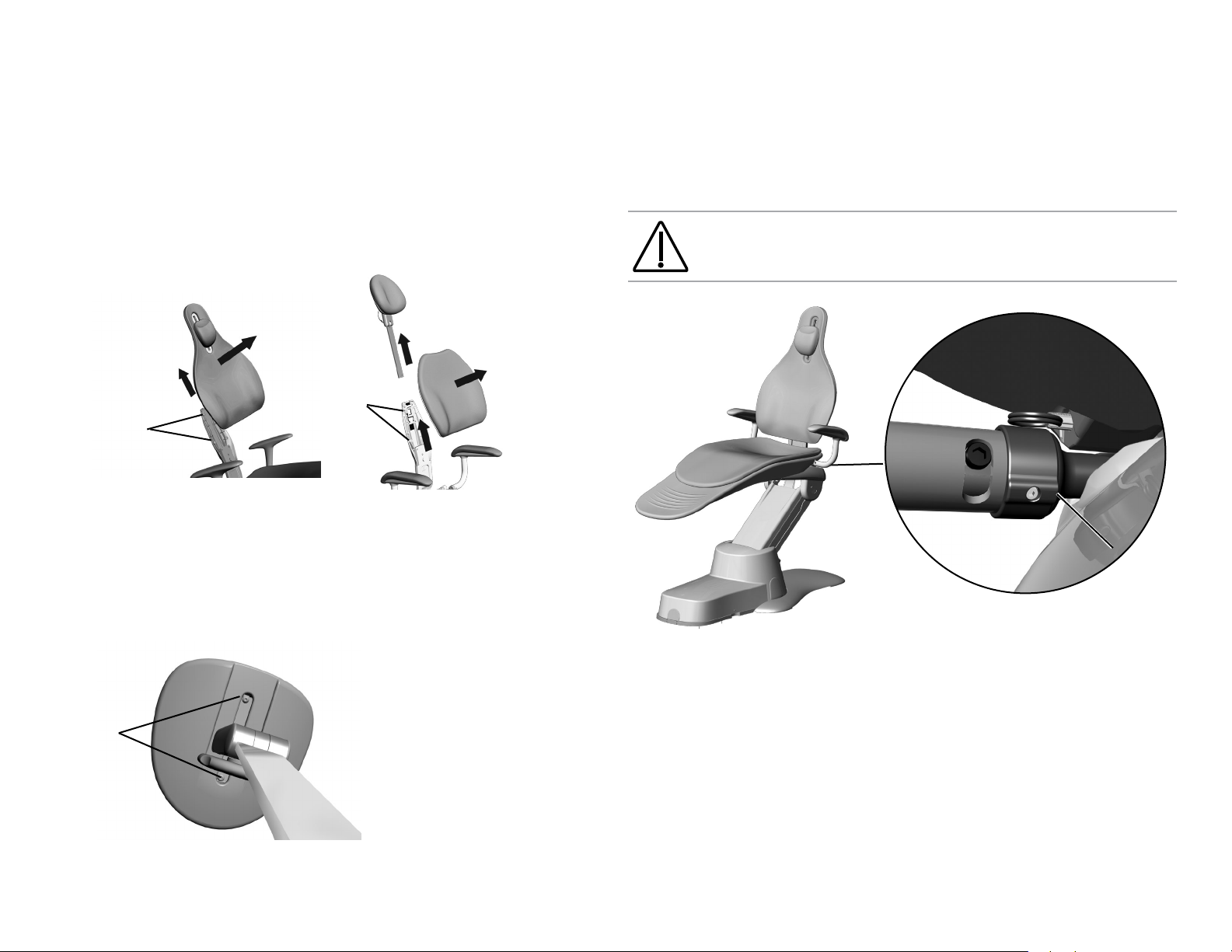
Dual-Articulating Headrest [311 (A and B)/411]
Headrest Adjustment
The dual-articulating headrest offers a “glide” feature, as well as
manual articulation. The locking knob allows you to adjust the headrest
for a full range of positions.
Release the headrest by turning the locking knob to the left, then adjust
the headrest for a proper fit. Lock the headrest in the desired position
by turning the knob to the right. For minor height adjustment, slide
the headrest cushion up and down. For additional height adjustment,
reposition the glide bar.
Glide Bar Tension Adjustment
A dual-articulating headrest may be difficult to move or may drift
downward because of the amount of tension on its glide bar. To adjust
the tension, use a 1/8" hex key and turn the tension adjustment screw to
the right to increase friction or to the left to decrease friction.
Headrest
Note: This neckrest can
rotate/mount two ways.
Neck Support Track
Note: This neckrest can
only mount one way.
Effective October 2013
Locking
Knob
Glide Bar
1/8” Hex Key
Note: the lever headrest is
an option for the 411 chair..
Page 27

Two-Position Armrest Adjustments [311 (A)]
Armrests Repositioning
Pull or push the armrests to reposition them in the forward or backward
position. The armrests can also be locked into the upright position.
Armrests Locking
The armrests can be unlocked from the upright position. Using a 3/16''
hex key, remove the rotational stop screw from the back of the armrest
and install it in the front of the armrest.
Effective October 2012
Effective October 2012
Stop Screw in Front for
Positional Armrest
Stop Screw in Back
for Locked Armrest
Before October 2012
Before October 2012
86.0380.00 Rev B 311 (A) Chair Service, Adjustments, and Maintenance 27
Page 28

A-dec 311, 411, and 511 Dental Chairs Service Guide 311 (B) and 411 Chairs Service, Adjustments, and Maintenance 28
311 (B) and 411 Chairs Service, Adjustments, and Maintenance
Chair Covers
Remove the chair motor pump, lift arm and stop
plate covers in the following order:
CAUTION When removing or
replacing covers, take care not to
damage any wiring or tubing. Verify
that the covers are secure after
replacing them.
1. Motor Pump Cover: Remove the screw from
each side of the cover and lift up.
2. Lift Arm Cover: Position the chair so it is
raised half way up. Pull one side of the cover
until it releases from the lift arm. To replace,
align one side of the cover with the lift arm
and insert it into place. Ensure both sides are
firmly attached.
3. Stop Plate: Pull one side of the cover until it
releases from the lift arm. To replace, slide
one side of the cover over the post on the lift
arm and attach.
Side Cover [311 (B) and 411 only]
Rear Cover
Assembly
Lift Arm Cover
Rear Cover
or
Swivel Cover
Stop Plate Cover
Side Cover [311 (B) and 411 only]
Motor Pump Cover
A-dec 311 B Shown
Page 29

Upholstery [311 (B) and 411]
Back Upholstery Removal/Attachment
NOTE The 311 (B) and 411 upholstery backs are not
interchangeable.
To remove the back, firmly grasp the bottom edge of the cushion and lift
up, then lift the upholstery out and away from the chair back support.
To reattach the back upholstery, place the key holes on the cushion over
the large fastener heads, then push down until it inserts into position.
Headrest Upholstery Removal/Attachment
Seat Upholstery Removal/Attachment
To remove the seat upholstery, move the armrests forward and pull out
the side covers. Remove the pins that are under the chair frame, then
lift upholstery off of the frame. To reattach, move the armrests forward,
line up the holes in the seat upholstery with the holes in the chair frame.
Push the pins through the seat upholstery and chair frame until the
rings touch the seat, then reinstall the covers.
Locking knob and lever release headrests are used with the
A-dec 311 (B) and 411. The headrest upholstery installs the same way for
both styles. The locking knob headrest is shown.
To remove the headrest upholstery, position the headrest to access the
two screws on the back, loosen the screws, and remove the upholstery.
To reattach, position the headrest to access the screws, place the
upholstery on the headrest, then insert and tighten the screws.
Screws
86.0380.00 Rev B 311 (B) and 411 Chairs Service, Adjustments, and Maintenance 29
A-dec 411 Shown
Page 30

A-dec 311, 411, and 511 Dental Chairs Service Guide 311 (B) and 411 Chairs Service, Adjustments, and Maintenance 30
Chair Drive System [311 (B) and 411]
The hydraulic chair system controls the base movement of the chair. An
electro-mechanical tilt actuator controls the back movements.
The chair seat has a vertical range of 13.75" (349 mm) to 31.5" (800 mm)
above the floor.
311 (B) and 411 (effective January 2015) include an adjustable BASE
DOWN speed adjustment: To adjust the BASE DOWN: Use a 3/32" hex
key to adjust the speed.
To slow the base down, turn the set screw clockwise.
To speed up the base down, turn the screw counterclockwise.
Page 31

Hydraulic System [311 (B) and 411]
The hydraulic system deactivates automatically at the upper and
lower extremes of travel. The system is leak-free during transportation,
storage, and operation. The hydraulic system consists of hydraulic fluid
reservoir, hydraulic cylinders, and motor-driven hydraulic pump with
solenoids.
CAUTION Use only A-dec hydraulic fluid, p/n 61.0197.00.
Hydraulic Fluid Reservoir Replenishment [311 (B) and 411]
The hydraulic fluid reservoir is located in the lift arm of the chair under
the stop plate cover. You can see through the translucent material to
determine the fluid level in the reservoir.
Add hydraulic fluid to the reservoir:
1. Raise the chair to the full base up position.
2. Fill the reservoir with hydraulic fluid to the top of the fluid level
indicator.
CAUTION Do not overfill.
Fluid Level
Indicator
3. Move the chair down and up after fluid has been added.
86.0380.00 Rev B 311 (B) and 411 Chairs Service, Adjustments, and Maintenance 31
Page 32

A-dec 311, 411, and 511 Dental Chairs Service Guide 311 (B) and 411 Chairs Service, Adjustments, and Maintenance 32
BACK
BASE
43.0363.00
Factory Default Routine [311 (A and B) and 411]
CAUTION The position sensors can be inadvertently installed
upside down. Improper installation will limit the chair’s
functionality.
After installing a new chair, circuit board, or position sensor, run the
factory default routine. The routine:
• Sets the chair base and back upper limits
• Calculates new preset positions based on actual range of motion
of the chair
• Verifies that the position sensors work correctly
To start the factory default routine, place the spare jumper in the factory
default position on the P3 test points of the chair circuit board.
CAUTION Circuit boards are sensitive to static electricity.
Electrostatic Discharge (ESD) precautions are required when
touching a circuit board or making connections to or from
the circuit board. Circuit boards should be installed only by
an electrician or qualified service person.
Jumper in
Factory
Default
Position
When running the factory default routine, the chair:
1. Moves base down.
2. Moves base up.
3. Moves back down.
4. Moves back up.
5. Moves base and back to mid position.
6. Moves back and base down.
7. Moves base and back to mid position.
8. Moves base and back to Entry/Exit.
9. Three beeps confirm the routine completed successfully.
Once the routine completes, place the jumper into the Spare position
on P3.
NOTE The jumper must remain in the factory default
position to complete the factory default routine. The status
LEDs on the standard and deluxe touchpads and the chair
circuit board double blink while the factory default routine
is running and after the routine is complete. When the
routine is complete, three beeps sound. If the routine stops
prematurely, one beep sounds.
NOTE One beep indicates the routine failed to complete. See
page 56 for troubleshooting.
Page 33

Capacitor Replacement [311 (B)/411]
The hydraulic system used for the chair’s base movement is operated
using a motor capacitor, located in the power supply of the chair. There
are three specific capacitors for different line voltage ranges. The chair
motor capacitor can be replaced within the power supply.
DANGER Turn off the power to the system before you
continue with this procedure. Failure to do so can result in
electrical shock.
WARNING Turn off the power to the system before you
continue with this procedure. Failure to do so can result in
product damage, serious injury, and/or death.
Chair Input Voltages
Mains Chair Input Voltage A-dec Capacitor Part Number
100 VAC 90.1198.00
110 - 120 VAC 90.1199.00
220 - 240 VAC 90.1200.00
86.0380.00 Rev B 311 (B) and 411 Chairs Service, Adjustments, and Maintenance 33
Capacitor
Page 34

A-dec 311, 411, and 511 Dental Chairs Service Guide 311 (B) and 411 Chairs Service, Adjustments, and Maintenance 34
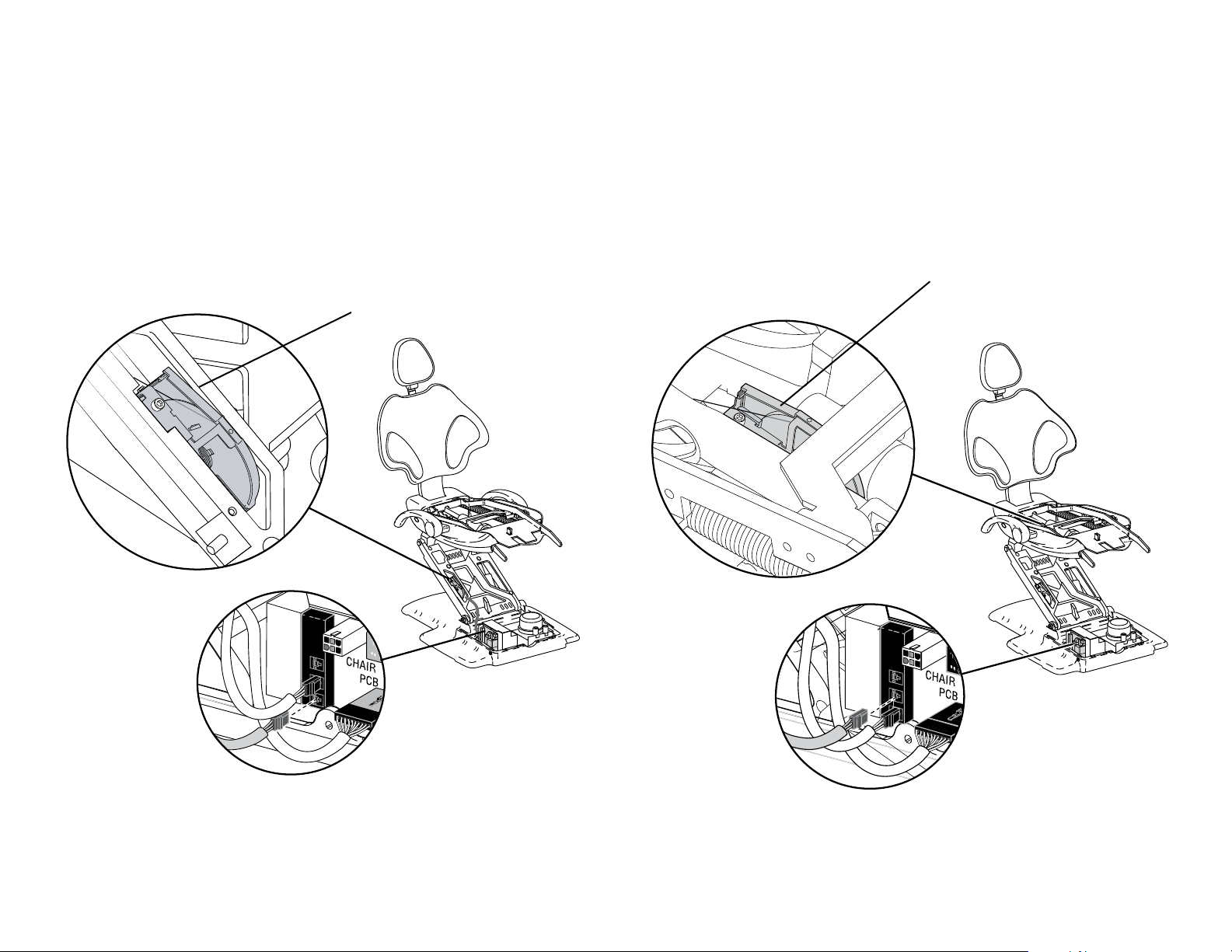
Motor Driven Electro-Mechanical Actuator [311 (B) and 411]
The back-up and back-down movements are controlled with an electro-mechanical tilt actuator, which is located under the seat of the chair.
Reference the chart below to identify the location of actuators and switches.
Tilt Actuator
Tilt Actuator Switch (411 only)
Back Position Sensor
A-dec 411 shown
Stop Switch
Base Position Sensor
Page 35

Position Sensor [311 (A and B)/411]
The position sensor circuit boards provide positioning data to the chair
board. There is a position sensor for the back and a position sensor for
the base.
CAUTION The position sensors can be inadvertently installed
upside down. Improper installation will limit the chair’s
functionality.
A diagnostic LED is provided on the chair board for each position
sensor. Refer to Chair Circuit Board LED Identification, see page 12
for information. An additional LED, indicating power, is present on
each position sensor circuit board.
LED
Factory Default Routine
If a position sensor or chair board are replaced, run the factory default.
For instructions on running the factory default, see page 32.
Limp Along Feature
There are two position sensors, one for the base of the chair and one for
the back of the chair. If there is a problem or malfunction with a position
sensor, the limp along feature allows the operator to move the chair in
the up direction for one to three second intervals by pushing the manual
control buttons on the touchpad or footswitch. Refer to Chair Circuit
Board LED Identification, page 12 for further information. When in
limp along mode, presets will not function.
Red
Green
Black
86.0380.00 Rev B 311 (B) and 411 Chairs Service, Adjustments, and Maintenance 35
Black
Page 36

A-dec 311, 411, and 511 Dental Chairs Service Guide 311 (B) and 411 Chairs Service, Adjustments, and Maintenance 36
Solenoid [311 (B) and 411]
p/n: 62.0317.00 21.6 VDC
Solenoid Testing
A solenoid is energized during base down function. To determine if
a solenoid has failed, check for coil resistance using magnetic pull or
volt/ohm meter test.
Magnetic Pull Test for Coil Resistance
1. Hold a paper clip loosely in your hand.
2. Activate the solenoid by pressing base down on the footswitch or
touchpad.
3. If there is a pull on the paper clip, the solenoid is being energized.
Paper
Clip
Volt/Ohm Meter Test for Coil Resistance
DANGER Turn off the power to the system before you
continue with this procedure. Failure to do so can result in
electrical shock.
WARNING Turn off the power to the system before you
continue with this procedure. Failure to do so can result in
product damage, serious injury, and/or death.
1. Disconnect the solenoid power at the chair board’s base solenoid
terminal strip (J7).
2. Place one Ohm meter probe on each of the solenoid wires.
Solenoid=38Ohms(Ω)±4Ohms(Ω)
J7
Solenoid
Page 37

Solenoid Assembly Replacement [311 (B) and 411]
4. Loosen the nut on the solenoid and use a screw driver to remove
the failed solenoid assembly.
CAUTION The circuit board is static sensitive. ESD
precautions are required. The circuit board should be
installed by an electrician or qualified service personnel.
WARNING Lower the chair base to the mechanical limit
before removing the solenoid.
Remove the Solenoid Assembly:
When replacing a solenoid wipe up any fluid and replace existing
O-rings on the solenoid base.
1. Remove the utility cover(s).
2. To minimize pressure in the hydraulic system, lower the chair base
to the mechanical limit.
DANGER Turn off the power to the system before you
continue with this procedure. Failure to do so can result
in electrical shock.
WARNING Turn off the power to the system before you
continue with this procedure. Failure to do so can result
in product damage, serious injury, and/or death.
3. Disconnect the solenoid from the chair circuit board, terminal
strip J7.
NOTE Cover the solenoid with a rag. Fluid is still under
pressure when removing the solenoid.
5. Wipe up any fluid and replace existing O-rings on the solenoid base.
Install the New Solenoid Assembly:
1. Install the new solenoid.
2. Reconnect the solenoid to the chair circuit board, terminal strip J7. It
does not matter which solenoid wire goes into which terminal. The
solenoid will work either way.
3. Turn on the power.
4. Move the chair up and down to ensure there are no leaks.
5. Reinstall the utility cover.
86.0380.00 Rev B 311 (B) and 411 Chairs Service, Adjustments, and Maintenance 37
Page 38

A-dec 311, 411, and 511 Dental Chairs Service Guide 311 (B) and 411 Chairs Service, Adjustments, and Maintenance 38
BACK
BASE
Chair Stop Plate [311 (B) and 411]
Stop Switch
If an object presses against the chair stop plate as the chair is lowered,
a stop switch will interrupt and reverse the chair motion. If the
object becomes lodged, press the base up button on the footswitch or
touchpad. Remove the object and resume normal chair operation.
WARNING Be sure to turn off power to the chair and
disconnect it from its power source before replacing the stop
switch.
CAUTION Use cable ties to secure wires to the lift arm to
prevent kinking and pinching.
Chair Bump-Up Feature [311 (B) and 411]
The chair stop plate triggers the chair to move upwards if it was moving
down when the stop plate switch was activated.
Chair Stop Plate
Stop Switch
Assembly
A-dec 411 Shown
Page 39

Dual-Articulating Headrest [311 (A)/311 (B)/411]
Headrest Adjustment
The dual-articulating headrest offers a “glide” feature, as well as
manual articulation. The locking knob allows you to adjust the headrest
for a full range of positions.
Headrest
Locking
Knob
Release the headrest by turning the locking knob to the left, then adjust
the headrest for a proper fit. Lock the headrest in the desired position
by turning the knob to the right. For minor height adjustment, slide
the headrest cushion up and down. For additional height adjustment,
reposition the glide bar.
Glide Bar Tension Adjustment
A dual-articulating headrest may be difficult to move or may drift
downward because of the amount of tension on its glide bar. To adjust
the tension, use a 1/8" hex key and turn the tension adjustment screw to
the right to increase friction or to the left to decrease friction.
Glide Bar
1/8” Hex Key
Headrest
Lever (411 only)
Glide Bar
1/8” Hex Key
86.0380.00 Rev B 311 (B) and 411 Chairs Service, Adjustments, and Maintenance 39
Page 40

A-dec 311, 411, and 511 Dental Chairs Service Guide 311 (B) and 411 Chairs Service, Adjustments, and Maintenance 40
Armrest Adjustments [311 (B) and 411]
Two-Position Armrests Adjustment
Push or pull the armrests to reposition them in the forward or back
position
Arm Rest Rotation Tension Adjustment
If the armrests become loose or are difficult to move, you can adjust the
rotation tension. To adjust each armrest:
1. Remove the chair side cover by pulling on the left and lower right
sides of the cover. Pull the cover out of the way to access the adjustment screw.
2. Use a 5/32" hex key and turn clockwise to tighten or counterclockwise to loosen the armrest tension. Only a small adjustment is
needed to significantly increase or decrease tension.
5/32"
Hex Key
2
1
1
2
A-dec 411 Shown
Page 41

Swivel Brake Adjustment [311 (B) and 411]
Swivel Brake Tension Adjustment
Swivel Brake
The chair can rotate to any position within 30° either side of center. The
chair swivel brake locks the chair in the selected position. To engage the
brake, push the brake lever firmly to the left. To release the swivel brake,
push the brake lever to the right.
NOTE The 311 (Version B) Dental Chair may not have the
swivel break feature.
If the chair swivels left or right with the brake engaged, or is difficult
to move with the brake disengaged, adjust the swivel brake tension.
Properly tensioned, the brake handle should be in the middle when it is
fully engaged. To make the adjustment:
1. Move the brake handle to the right.
2. If the chair includes a back mount module, swivel the chair to
access the adjustment screw.
3. Use a 7/64" hex key with a long shaft to turn the tension adjustment screw clockwise to increase brake friction or counterclockwise
to decrease brake friction. Only a small adjustment is needed to
significantly increase or decrease tension.
NOTE To disable the swivel feature, reinstall the shipping
pin.
Hex Key
A-dec 411 Shown
86.0380.00 Rev B 311 (B) and 411 Chairs Service, Adjustments, and Maintenance 41
Page 42

A-dec 311, 411, and 511 Dental Chairs Service Guide 511 Chair Service, Adjustments, and Maintenance 42
511 Chair Service, Adjustments, and Maintenance
Chair Covers (511)
Remove the chair motor pump, lift arm and stop plate
covers in the following order:
CAUTION When removing or replacing
covers, take care not to damage any wiring
or tubing. Verify that the covers are secure
after replacing them.
1. Motor Pump Cover: Remove the screws from each
side and lift up.
2. Lift Arm Cover: Position the chair so that it is
raised half way up. Pull one side of the cover
until it releases from the lift arm. To replace, align
one side of the cover with the lift arm and insert it
into place. Ensure both sides are firmly attached.
3. Stop Plate: Pull one side of the cover until it
releases from the lift arm. To replace, slide one
side of the cover over the post on the lift arm and
attach.
Rear Cover Assembly
Left Side Cover
Lift Arm Cover
Right Side Cover
Stop Plate Cover
Motor Pump Cover
Page 43

Upholstery (511)
Back Upholstery Removal/Attachment
To remove the back, firmly grasp the bottom edge of the cushion and lift
up, then lift the upholstery out and away from the chair back support.
To reattach the back upholstery, place the key holes on the cushion over
the large fastener heads, then push down until it inserts into position.
Headrest Upholstery Removal/Attachment
To remove the headrest upholstery, position the headrest to access the
two screws on the back, loosen the screws, and remove the upholstery.
To reattach the headrest upholstery, position the headrest to access the
screws, place the upholstery on the headrest, then insert and tighten the
screws.
CAUTION Do not remove the positioning mechanism screws
or plate. The brake assembly will fall out.
Upholstery Screws
Seat Upholstery Removal/Attachment
To remove the seat, first remove the plastic clip under the seat frame,
then lift the toe of the seat to unhook it from the chair carriage, and
move it away. To reattach, place the two seat upholstery hooks under
the chair carriage, then push the toeboard back and down until the lock
is through the seat frame. Insert the clip into the lock.
86.0380.00 Rev B 511 Chair Service, Adjustments, and Maintenance 43
Page 44

A-dec 311, 411, and 511 Dental Chairs Service Guide 511 Chair Service, Adjustments, and Maintenance 44
Factory Default Routine (511)
After installing a new chair, circuit board, or position sensor, run the
factory default routine. The routine:
• Sets the chair base and back upper limits
• Calculates new preset positions based on actual range of motion
of the chair
• Verifies that the position sensor work correctly
To start the factory default routine, place the spare jumper in the factory
default position on the P3 test points of the chair circuit board.
CAUTION Circuit boards are sensitive to static electricity.
Electrostatic Discharge (ESD) precautions are required when
touching a circuit board or making connections to or from
the circuit board. Circuit boards should be installed only by
an electrician or qualified service person.
NOTE The jumper must remain in the factory default
position to complete the factory default routine. The status
LEDs on the standard and deluxe touchpads and the chair
circuit board double blink while the factory default routine
is running and after the routine is complete. When the
routine is complete, three beeps sound. If the routine stops
prematurely, one beep sounds.
When running the factory default routine the chair:
1. Moves base down
2. Moves base up
3. Moves back down
4. Moves back up
5. Moves base and back to Position 0
6. Beeps three times
NOTE One beep indicates the routine failed to complete. See
page 56 for troubleshooting.
Jumper in Factory
Default Position
Page 45

Chair Drive System (511)
Hydraulic Cylinders
The hydraulic cylinders operate during the base up and back up
functions. Springs and gravity retract the piston during base down and
back down functions.
The chair seat has a vertical range of 13.5" (343 mm) to 31.5" (800 mm)
above the floor.
Motor Driven Hydraulic Pump
During base and back up functions, the hydraulic pump transfers
hydraulic fluid from the reservoir to the base and back hydraulic
cylinders. Solenoids, mounted to the pump assembly, control the flow
of hydraulic fluid back to the reservoir during base and back down
functions.
NOTE You cannot adjust the speed of the chair.
86.0380.00 Rev B 511 Chair Service, Adjustments, and Maintenance 45
Page 46

A-dec 311, 411, and 511 Dental Chairs Service Guide 511 Chair Service, Adjustments, and Maintenance 46
Hydraulic System (511)
The hydraulic system deactivates automatically at the upper and
lower extremes of travel. The system is leak-free during transportation,
storage, and operation. The hydraulic system consists of hydraulic fluid
reservoir, hydraulic cylinders, and motor-driven hydraulic pump with
solenoids.
CAUTION Use only A-dec hydraulic fluid, p/n 61.0197.00.
Hydraulic Fluid Reservoir Replenishment (511)
The hydraulic fluid reservoir is located in the lift arm of the chair under
the stop plate cover. You can see the fluid level in the reservoir through
the sides of the reservoir. Add hydraulic fluid to the reservoir:
1. Raise the chair to the full base up and back up position.
2. Fill the reservoir with hydraulic fluid to the top of the fluid level
indicator.
CAUTION Do not overfill.
3. Move the chair down and up after fluid has been added.
Fluid Level
Indicator
Page 47

Capacitor (511)
p/n: 041.642.00, 100 VAC, 041.643.00, 110 - 120 VAC, 041.644.00, 220 - 240 VAC
The capacitor is energized during chair base up or back up functions.
Capacitor
86.0380.00 Rev B 511 Chair Service, Adjustments, and Maintenance 47
Page 48

A-dec 311, 411, and 511 Dental Chairs Service Guide 511 Chair Service, Adjustments, and Maintenance 48
Solenoid (511)
p/n: 90.1070.00, 110 - 120 VAC, 90.1071.00, 220 - 240 VAC
Solenoid Testing
A solenoid is energized during base down and back down functions.
To determine if a solenoid has failed, check for coil resistance using
magnetic pull or volt/ohm meter test.
Magnetic Pull Test for Coil Resistance
1. Hold a paper clip loosely in your hand.
2. Activate the solenoid by pressing base down or back down on the
footswitch or touchpad.
3. If there is a pull on the paper clip, the solenoid is being energized.
Volt/Ohm Meter Test for Coil Resistance
DANGER Turn off the power to the system before you
continue with this procedure. Failure to do so can result in
electrical shock.
WARNING Turn off the power to the system before you
continue with this procedure. Failure to do so can result in
product damage, serious injury, and/or death.
1. Disconnect the solenoid power at the 2-position connector.
2. Place on Ohm meter probe on each solenoid connector terminals.
• 100-120VAC=177Ohms±18Ohms
• 220-240VAC=845Ohms±85Ohms
Page 49

Solenoid Assembly Replacement (511)
CAUTION Circuit boards are sensitive to static electricity.
Electrostatic Discharge (ESD) precautions are required when
touching a circuit board or making connections to or from
the circuit board. Circuit boards should be installed only by
an electrician or qualified service person.
WARNING Lower the chair base to the mechanical limit
before removing the solenoid.
Remove the Solenoid Assembly:
When replacing a solenoid wipe up any fluid and replace existing
O-rings on the solenoid base.
1. Remove the utility cover(s).
2. To minimize pressure in the hydraulic system, lower the chair base
and back to the mechanical stops.
Four Screws
DANGER Turn off the power to the system before you
continue with this procedure. Failure to do so can result
Solenoid
Connector
in electrical shock.
WARNING Turn off the power to the system before you
Install the New Solenoid Assembly:
continue with this procedure. Failure to do so can result
in product damage, serious injury, and/or death.
1. Insert the new solenoid and fasten it with the four screws.
2. Reconnect the solenoid connector.
3. Disconnect the solenoid connector.
4. Use a 9/64" hex key to remove the four screws that fasten the
solenoid assembly.
5. Wipe up any fluid and replace three O-rings on the solenoid base.
86.0380.00 Rev B 511 Chair Service, Adjustments, and Maintenance 49
3. Turn on the power.
4. Run the chair through its full range of motion to check for leaks.
5. Reinstall the utility cover.
Page 50
A-dec 311, 411, and 511 Dental Chairs Service Guide 511 Chair Service, Adjustments, and Maintenance 50
Position Sensors (511)
The position sensor and cable assembly eliminates position float (a slight change or variation in the pre-programmed positions). The chair uses the
same position sensor assembly for both lift and tilt requirements. If a position sensor fails, the limp-along feature allows the operator to position the
chair for one second intervals by pushing the manual control buttons on the touchpad or footswitch.
Back Position Sensor
Base Position Sensor
Page 51

Chair Stop Plate (511)
Stop Switch
If an object presses against the chair stop plate as the chair is lowered,
a stop switch will interrupt and reverse the chair motion. If the object
becomes lodged, press base up on the footswitch or touchpad. Remove
the object and resume normal chair operation.
WARNING Be sure to turn off power to chair and disconnect
it from its power source before replacing the stop switch.
CAUTION Use cable ties to secure the wires to the lift arm to
prevent kinking and pinching.
Chair Bump-Up Feature (511)
The chair stop plate and the assistant’s arm trigger the chair to move
upwards if it was moving down when the stop plate switch was
activated.
Stop Switch
Assembly
Chair Stop Plate
86.0380.00 Rev B 511 Chair Service, Adjustments, and Maintenance 51
Page 52

A-dec 311, 411, and 511 Dental Chairs Service Guide 511 Chair Service, Adjustments, and Maintenance 52
Headrest Adjustment (511)
The headrest adjustment lever allows you to use one hand to adjust the
headrest. When the lever is released, the headrest holds its position.
If the headrest drifts downward, or if it is difficult to move up or down,
adjust the glide bar tension. To adjust the tension, use a 1/8" hex key
and turn the tension adjustment screw clockwise to increase friction or
counterclockwise to decrease friction.
Glide
Bar
Headrest
Adjustment Lever
1/8” Hex Key
Glide Bar Tension Adjustment
Page 53

Swivel Brake Adjustment (511)
Swivel Brake Tension Adjustment
Swivel Brake Operation
The chair can rotate to any position within 30° either side of center. The
chair swivel brake keeps the chair from moving. To engage the brake,
push the brake lever firmly to the left. To release the swivel brake, push
the brake lever to the right.
NOTE To disable the swivel feature, reinstall the shipping
pin.
If the chair swivels left or right with the brake engaged, or is difficult
to move with the brake disengaged, adjust the swivel brake tension.
Properly tensioned, the brake handle should be in the middle when it is
fully engaged. To make the adjustment:
1. Move the brake handle to the right.
2. Use a 7/64" hex key to turn the tension adjustment screw clockwise
to increase brake friction or counterclockwise to decrease brake friction. Only a small adjustment is needed to significantly increase or
decrease tension.
Tension
Adjustment Screw
Engaged
86.0380.00 Rev B 511 Chair Service, Adjustments, and Maintenance 53
Released
Page 54

A-dec 311, 411, and 511 Dental Chairs Service Guide Chair Programming 54
Chair Programming
Overview
A-dec dental chairs can be operated by the A-dec touchpads (Standard, 300 Deluxe, or 500 Deluxe) or the footswitch. Chair functions are similar
whether used with an A-dec touchpad or footswitch.
A-dec Standard Touchpad
(Current Model)
A-dec Standard Touchpad
(Original Model)
A-dec 500 Deluxe Touchpad
(Current Model)
A-dec 500 Deluxe Touchpad
(Original Model)
A-dec 300 Deluxe Touchpad
A-dec Footswitch
System Status Light
On chairs with an A-dec delivery system, the A-dec logo on the touchpad indicates
the system status. A solid blue status light indicates that power is on.
A blinking blue status light could indicate that something is lodged under the chair,
activating the stop plate or limit switch. Once the object is removed, the status light
returns to solid blue.
A double blinking blue status light could also indicate that a jumper is in the factory
default position on the chair circuit board. See page 56 for troubleshooting.
A-dec Logo/
Status Light
Page 55

Chair Positioning
Program Chair Preset Buttons
Chair Direction Buttons
The touchpad or footswitch provide manual and programmed controls
for A-dec chair positioning. The direction arrows allow you to manually
move the chair base and back up and down.
Footswitch
Standard and 500
Deluxe Touchpad
300 Deluxe
Touchpad
Action
Back Down
Base Down
Back Up
Base Up
Programmable Chair Buttons/Factory Presets
Chair position buttons are factory preset to automatically move the chair.
Footswitch
Buttons
Touchpad
Buttons
Description
Entry/Exit: Automatically positions chair for entry/exit and turns
off dental light.
Treatment 1: Automatically positions the chair base and back
down and turns on the dental light.
NOTE To stop the chair at any point, push any chair
positioning button on the footswitch or touchpad.
To program the chair presets Entry/Exit, Treatment 1, and Treatment 2:
1. Move the chair to its desired position.
2. Press and release the Program button. One beep indicates
programming mode.
3. Press the button you want to program and you hear three beeps
confirming the button has been set.
Customize the X-Ray/Rinse Button
The X-ray/Rinse button functions either as x-ray/rinse or as another
preset position (Treatment 3). To change the function of the X-ray/Rinse
button:
1. Press and hold the Program and X-ray/Rinse buttons
simultaneously for three seconds.
• One beep indicates the button has been configured as
Treatment 3.
• Three beeps indicate that the X-ray/Rinse button has been
configured as the x-ray/rinse function (toggles between the
x-ray/rinse and the previous position.)
2. Program the preset position as instructed under “Program Chair
Preset Buttons” above.
Treatment 2 (not available on 300 Deluxe touchpad):
Automatically positions the chair base and back and turns on
the dental light.
X-ray/Rinse: Automatically toggles between the X-ray/Rinse and
the current chair position. The dental light turns off when the
chair is positioned for X-ray/Rinse and turns on when it returns
to its last position.
86.0380.00 Rev B Chair Programming 55
Page 56

A-dec 311, 411, and 511 Dental Chairs Service Guide Troubleshooting 56
Troubleshooting
Overview
This section contains troubleshooting information to assist in diagnosing the problems that are most likely to occur. This information is not
intended to be all inclusive. Contact A-dec Customer Service if troubleshooting assistance is required. See page 4 for contact information.
A-dec 311 (A and B) and 411 Dental Chairs Troubleshooting
A-dec 311 (A and B) and 411 Dental Chairs
Symptom Check Possible Solution
No power . Check the circuit breakers on the integrated 300 watt power supply. If circuit breakers are tripped, reset them. If they still trip after resetting, disconnect
all cables from the chair circuit board and:
1. Reset the circuit breaker.
2. Reconnect the cables one at a time, observing which one causes the circuit to
trip.
Replace the faulty cable or power supply.
No power, circuit breakers
are not tripped.
Chair “limps along.” The
base or back moves only
about one inch (a few
centimeters) at a time, and
then stops.
Chair “loses memory.”
Manual functions or preset
functions randomly stop.
Check that the master toggle is on and the power switch at the base
of the chair is on.
Check for air pressure at the air electric switch or that the air
electric pressure is functional.
Check the position sensor. 1. Check the power LED on the position sensor circuit board. It should be on. If it is
Check to see if there is a DCS compatible light connected to the
system.
Press the power button at the base of the chair. If the symptoms are unchanged, follow
the steps below.
If there is a yellow tubing going to the air electric switch on the power supply:
1. Turn the master toggle off and bleed the air from the system.
2. Remove the yellow tubing from the air electric switch on the power supply.
3. Turn the master toggle on and check for air.
• If there is no air, troubleshoot the air supply.
• If there is air, bypass the air electric switch by ipping the rocker switch
below the tubing connection. If power is present with the switch bypassed,
replace the air electric switch.
off, the position sensor may be unplugged, not receiving power from the circuit
board, or may have a faulty cable.
2. Check the diagnostic LED on the chair circuit board for the position sensor.
3. Check the position sensor circuit board for signs of moisture or damage.
4. Contact Customer Service.
1. Unplug the data cable from the chair circuit board to the light and test the system.
2. If the system functions, run an external data cable from the circuit board to the
chair and test the system again.
• If the system functions, replace the data cable.
• If the system doesn't function, contact Customer Service.
Page 57

A-dec 311 (A and B) and 411 Dental Chairs
Symptom Check Possible Solution
Base doesn't move to the full
range of motion.
Check that the position sensor wires are connected and not
damaged.
Check to see if an optional height limit has been set. Optional height limits can be set to prevent the base from travelling the full range of
Reconnect or replace the position sensor. If the base still doesn't move to the full
range of motion, follow the steps below.
motion. Running factory default will not remove optional height limits. To remove:
Move the jumper on the testpoints from the SPARE position to EN/DS/TP/FS.
1. Press and hold the button on the touchpad or footswitch that is not functioning
correctly. For example, if the base is not travelling the full range of motion, press
and hold the base up button.
• One beep conrms a height limit is removed, three beeps conrms a new
height limit has been set.
2. Remove the jumper from EN/DS/TP/FS and test the system function again.
Limited or no movement
from the footswitch.
No back up or down
movement.
No base up movement. Check the chair movement with testpoints. Remove the touchpad or footswitch cable and move the chair with the testpoints on
Check for a broken or disconnected footswitch cable. Reconnect or replace the footswitch cable.
Check if the chair back motor is disconnected. Plug in the chair back motor and test the chair movement again.
With the motor plugged in, check the voltage output from the chair
circuit board to the motor.
1. Set meter leads in the back side of the white Molex connector attached to the
motor.
2. The reading should be 20-22 VDC.
If voltage is not present, check the incoming power to the circuit board and replace
the chair circuit board if needed.
the chair circuit board.
If the chair moves from the testpoints on the circuit board, see “Limited or no
movement from footswitch.”
If the chair doesn't move from the testpoints, check the circuit board for loose or
broken wire connections going from the circuit board to the pump.
Reconnect the cables. If wire connections are functioning correctly, replace the
capacitor.
86.0380.00 Rev B Troubleshooting 57
Page 58

A-dec 311, 411, and 511 Dental Chairs Service Guide Troubleshooting 58
A-dec 311 (A and B) and 411 Dental Chairs
Symptom Check Possible Solution
No base down movement. Check the A-dec logo on the touchpad or the status LED on the chair
circuit board to see if the status light is blinking.
If the status LED is blinking, see "No base or back down function, up functions work
normally."
If the status LED is not blinking, check the touchpad and/or footswitch cables and
move the chair from the testpoints on the circuit board to see if the chair moves.
If the chair moves, see "limited or no movement from the footswitch."
Is DS12 illuminated when the base down is pressed?
• No -- replace the chair circuit board
• Yes -- look for kinked hydraulic hoses. If hoses are not kinked, replace the
solenoid.
No base or back down
movement, up moves
normally.
Check the A-dec logo on the touchpad or the status LED on the chair
circuit board to see if it is ashing.
If the LED is ashing, a safety switch has been activated. Remove any obstructions
from the chair path and test the system.
If the chair works, no further repairs are needed.
If the chair doesn't function, check the limit switch connections on the chair circuit
board (DS4 and DS18). Is DS4 illuminated?
311 (A) chair:
If DS4 or DS18 is illuminated, make sure jumpers are installed in P10 and P13.
Replace jumpers if they are not installed on the chair circuit board.
If the problem persists, replace the chair circuit board.
311 (B) chair:
If DS4 is illuminated, check the wire harness and connection for the base limit switch.
Remove the wire harness, and place a jumper in P10. Does the DS4 go off?
• Yes -- remove the jumper and replace the base limit switch.
• No -- replace the chair circuit board.
If DS18 is illuminated, check to see that there is a jumper installed in P13. Replace
the jumper if needed. If DS18 still doesn’t turn off, replace the chair circuit board.
411 chair:
If DS4 or DS18 is illuminated, remove wire harness and place a jumper in P10 or P13.
Does DS4 or DS18 turn off?
• Yes -- replace the base limit switch.
• No -- replace the chair circuit board.
Page 59

A-dec 511 Dental Chairs Troubleshooting
A-dec 511 Dental Chair
Symptom Check Possible Solution
No power. Check the circuit breakers on the integrated 300 watt power supply. If the circuit breakers are tripped, reset them. If they still trip after resetting,
disconnect all cables from the chair circuit board and:
1. Reset the circuit breaker.
2. Reconnect the cables one at a time, observing which one causes the circuit to
trip.
3. Replace faulty cable or power supply.
No power, circuit breakers
are not tripped.
Chair “limps along.” The
base or back moves only
about one inch at a time
then stops.
Chair “loses memory.”
Manual functions or preset
functions randomly stop.
Check the master toggle is on and the power switch at the base on
the chair is on.
Check for air pressure at the air electric switch or that the air electric
pressure is functional.
Check the base or back position sensor cable. Replace the position sensor as needed. Contact customer service for possible
Check to see if there is a DCS compatible light connected to the
system.
Press power button at the base of the chair. If symptoms persist, follow the steps
below.
If there is a yellow tubing going to the air electric switch on the power supply:
1. Turn the master toggle off and bleed the air from the system.
2. Remove the yellow tubing from the air electric switch on the power supply.
3. Turn the master toggle on and check for air.
• If there is no air, troubleshoot the air source.
• If there is air, bypass the air electric switch by ipping the rocker switch
below the tubing connection. If power is present with the switch bypassed,
replace the air electric switch.
warranty replacement.
1. Unplug the data cable from the chair circuit board to the light and test the system.
2. If it the system functions, run an external data cable from the chair circuit board
to the chair and test the system again.
• If the system functions, replace the data cable.
• If the system doesn't function, contact Customer Service.
86.0380.00 Rev B Troubleshooting 59
Page 60

A-dec 311, 411, and 511 Dental Chairs Service Guide Troubleshooting 60
A-dec 511 Dental Chair
Symptom Check Possible Solution
Base or back does not move
to the full range of motion.
Check that the position sensor wires are connected and not
damaged.
Reconnect or replace the position sensor.
Base only does not move to
the full range of motion.
Limited or no chair functions
from the footswitch.
No base or back up
movement. Base down
moves normally.
Check that the position sensor cables are connected to the right
position on the chair circuit board and are not swapped.
Check to see if an optional height limit has been set. Optional height limits can be set to prevent the base from travelling the full range of
Check for a broken or disconnected footswitch cable. Reconnect or replace the footswitch cable.
Check the footswitch functions. Unplug the footswitch cable from the chair circuit board and test chair functions from
Check the motor and capacitor connections at the chair circuit board. High voltage warning: If the relay clicks and DS9 (for back) or DS11 (for base)
The back position sensor should be connected at P1 and the base position sensor
should be connected at P2.
motion. Running factory default will not remove optional height limits. To remove:
1. Move the jumper on the testpoints from the SPARE position to EN/DS/TP/FS.
2. Press and hold the base up or base down button on the touchpad or footswitch.
For example, if the base is not going up all the way, press and hold the base up
button.
• One beep conrms a height limit is removed, three beeps conrms a new
height limit has been set.
3. Remove the jumper from EN/DS/TP/FS and test the system again.
the testpoints on the chair.
If the chair works from the testpoints and there is no damage to the footswitch cable,
replace the footswitch membrane.
illuminates, check the voltage going to the pump as follows:
1. Turn off power to the chair.
2. Place meter leads in the back of the white Molex connector going to the pump.
• Red wire = neutral
• Yellow wire = back up
• White wire with red stripe = base up
3. Turn the chair on and activate either base up or back up. The reading should be
around 120 VAC.
4. If the voltage is correct, replace the capacitor.
Page 61

A-dec 511 Dental Chair
Symptom Check Possible Solution
No base or back down
movements. Base up moves
normally.
Check the A-dec logo on the touchpad or the status LED on the chair
circuit board to see if it is ashing.
If the status LED is ashing:
A safety switch has been activated. Remove any obstructions from the chair path and
test the system.
If the chair functions, no further repairs are needed.
If the chair does not function, check the limit switch connection on the circuit board
(DS4). Is DS4 illuminated?
Yes -- Remove the limit switch wire harness from P10. Install a jumper into the limit
switch position P10.
Does the LED turn off?
• No- replace the chair circuit board.
• Yes- remove the jumper and plug in the limit switch connector. Replace the limit
switch.
Note: If there is equipment mounted on the back of the chair, there are two different
limit switches.
• Safety plate limit switch- under the safety plate
• Lower support arm switch- mounted on a plate underneath the brake handle.
To determine which switch has failed, disconnect the two switches and place the
jumper in the safety plate switch wire harness. Does DS4 on the chair circuit board
turn off?
• Yes -- replace the lower support arm limit switch.
• No -- replace the safety plate limit switch.
If the staut LED is not ashing:
Remove touchpad or footswitch and operate the chair from the testpoints on the chair
circuit board. If the chair functions, see “Limited or no functions from the footswitch.”
If the chair does not function, check DS10 (for back) or DS12 (for base) to see if they
turn on and you hear an audible "click" when the relay activates. If so, check the
following:
1. Check for kinks or pinches in the hydraulic hose.
2. Check for a defective solenoid by swapping the solenoid electrical connections.
For example, if the base won’t go down, swap the base and back solenoid cables,
and then press back down.
Does the base go down?
• Yes -- replace the chair circuit board.
• No -- replace the solenoid.
86.0380.00 Rev B Troubleshooting 61
Page 62

A-dec 311, 411, and 511 Dental Chairs Service Guide Troubleshooting 62
A-dec 511 Dental Chair
Symptom Check Possible Solution
No chair functions at all Check that the two screws on the bottom of the foot control are
secure.
Check DS3 on the chair circuit board If DS3 is illuminated, disconnect the data cable from the chair circuit board. Does DS3
If they are loose, tighten the screws and test the chair functions again.
turn off?
• Yes- the chair lockout signal is being generated from the delivery system. Call
Customer Service.
• No- the chair lockout signal is being generated at the chair circuit board. Replace
the chair circuit board.
Page 63

Chair Circuit Board Diagnostics
If you suspect that a circuit board may need replacing, use this circuit board replacement flowchart. Refer to one of the LED Identification tables for
help with diagnostics:
• 311/411 Chair Circuit Board LED Identification table, see page 13
• 511 Chair Circuit Board LED Identification table, see page 15
Disconnect P1, P2
and P5 on the
Chair circuit board.
Cycle power to
the board.
Is LED DS2 on
or blinking?
YES
NO
DO NOT replace
the circuit board.
Refer to the LED
tables for help in
determining the
source of the issue.
Is LED DS1 on
or blinking?
YES
NO
Replace the
circuit board.
DO NOT replace
the circuit board.
Refer to the LED
tables for help in
determining the
source of the issue.
86.0380.00 Rev B Troubleshooting 63
 Loading...