

Page 1
A-dec 500® Service Guide
Including ICV® and Clinical Products
Page 2

Copyright
Regulatory Information
©2012 A-dec Inc. All rights reserved.
A-dec Inc. makes no warranty of any kind with regard to this material,
including, but not limited to, the implied warranties of merchantability and
fitness for a particular purpose. A-dec Inc. shall not be held liable for any
errors contained herein or any consequential or other damages concerning the
furnishing, performance or use of this material. The information in this
document is subject to change without notice. If you find any problems in the
documentation, please report them to us in writing. A-dec Inc. does not
warrant that this document is error-free.
No part of this document may be copied, reproduced, altered, or transmitted in
any form or by any means, electronic or mechanical, including photocopying,
recording, or by any information storage and retrieval system, without prior
written permission from A-dec Inc.
Trademarks and Additional Intellectual Property Rights
A-dec, the A-dec logo, A-dec 500, A-dec 300, Cascade, Cascade Master Series,
Century Plus, Continental, Decade, ICX, ICV, Performer, Preference, Preference
Collection, Preference ICC, and Radius are trademarks of A-dec Inc. and are
registered in the U.S. and other countries. A-dec 200, Preference Slimline, and
reliablecreativesolutions are also trademarks of A-dec Inc. None of the
trademarks or trade names in this document may be reproduced, copied, or
manipulated in any manner without the express, written approval of the
trademarkowner.
Regulatory information is provided with A-dec equipment as mandated by
agency requirements. This information is delivered in the equipment’s
Instructions for Use or the separate Regulatory Information and Specifications
document. If you need this information, please go to the Document Library at
www.a-dec.com
.
Product Service
For service information, contact your local authorized A-dec dealer. To find
your local dealer, go to www.a-dec.com
.
Service Reference
This document is a companion to the A-dec 500 Service Reference
(p/n 86.0329.00). The Service Reference contains tubing, flow diagrams, and
illustrated parts breakdown content. Circuit board component information is
available in both this document and the Service Reference.
Certain touchpad symbols are proprietary to A-dec Inc. Any use of these
symbols, in whole or in part, without the express written consent of A-dec Inc.
is strictly prohibited.
Page 3

A-DEC 500
S
ERVICE GUIDE
Page 4

Page 5

CONTENTS
1 INTRODUCTION........................................................1
Inside This Guide....................................................................1
Document Conventions.............................................................1
Get Support .....................................................................2
Customer Service....................................................................2
Other Sources of Information ...............................................2
Genuine A-dec Parts Catalog......................................................2
A-dec Dental Furniture Technical Packet........................................2
A-dec Illustrated Parts Breakdown ...............................................2
Electronic Documentation .........................................................2
Serial, Model Numbers, Color Identification .............................3
Serial and Model Numbers .........................................................3
Service Tools ....................................................................4
2 DENTAL CHAIR ........................................................7
Product Overview..............................................................8
A-dec 511 Chair......................................................................8
A-dec 511 Chair Specifications....................................................8
Load Capacity ........................................................................... 8
Power On/Off Button .................................................................. 8
Limp-Along Feature .................................................................... 8
Chair Power Supply .................................................................... 9
Service, Usage, and Adjustments ......................................... 10
Chair Covers ....................................................................... 10
Factory Default Routine..................... ....... ........ ....... ........ ....... 11
Chair Circuit Board Components................................................ 12
LED Identification .....................................................................14
The Hydraulic System ............................................................ 15
Hydraulic Fluid Reservoir ............................................................15
Hydraulic Cylinders ...................................................................16
Motor Driven Hydraulic Pump .......................................................16
Capacitor ..............................................................................17
Solenoids ...............................................................................18
Test Solenoids .........................................................................18
Magnetic pull ...........................................................................18
Coil resistance .........................................................................18
Potentiometer......................................................................19
Chair Stop Plate ...................................................................20
Chair Bump-Up Feature ..............................................................20
Swivel Brake Adjustment.........................................................21
Tension Adjustment ...............................................................21
Headrest Adjustment .............................................................22
3 PROGRAMMING ...................................................... 23
Status Icon .....................................................................24
Chair Positioning..............................................................24
Position Buttons....................................................................24
Program Chair Preset Positions ......................................................25
Customize the X-Ray/Rinse Button .................................................25
Cuspidor Functions...........................................................26
Cupfill ...............................................................................26
Customize Cupfill and Bowl Rinse...............................................26
Dental Light....................................................................27
Dental Light Auto Feature........................................................27
A and B Buttons....................................................................27
Electric Handpiece Settings (Deluxe Touchpad Only) .................28
Standard Mode Programming ....................................................28
Standard Mode Display Settings .................................................29
Forward/Reverse Button .............................................................29
Endodontics Mode .................................................................30
Endodontics Mode Settings.......................................................31
Technician Setup Options...................................................32
Using Touchpad Buttons for Navigation ........................................32
Holder Setup .......................................................................32
Technician Help Messages........................................................36
Touchpad Circuit Board Components.....................................37
Standard Touchpad................................................................37
86.0348.00 Rev A i
Page 6

A-dec 500 and Clinical Products Service Guide Table of Contents ii
Deluxe Touchpad .................................................................. 38
4 DELIVERY SYSTEMS ................................................. 39
Delivery Systems Overview ...................................................... 39
Chair-Mounted Delivery Systems (532/533) ............................ 40
Product Overview (532/533) .............................................. 41
Service, Usage, and Adjustments (532/533) ........................... 42
Covers............................................................................... 42
Delivery System Cover ................................................................42
Delivery System Front Cover — Continental .......................................42
Whip Assembly..................................................................... 43
Continental Tray Holder (533 only)............................................. 43
Adjustments (532/533)........................................................... 44
Level Adjustment .....................................................................44
Tension Adjustment ...................................................................44
Front-to-Back Leveling ........................................................... 45
Side-to-Side Leveling ............................................................. 45
Side-Mounted Delivery Systems (542) ................................... 46
Product Overview (532/533/542 Common Feature)......................... 47
Service, Usage, and Adjustments (542) ................................. 48
Flexarm Counterbalance......................................................... 48
Remove covers..................................................................... 49
Rotational Tension Adjustment ................................................. 49
12 O’Clock Delivery Systems (541 and 545)............................ 50
Product Overview (541 and 545) ......................................... 51
A-dec 541 12 O’Clock Duo Delivery System ................................... 51
A-dec 541 Internal Components .....................................................51
Flex-Holder......................................................................... 52
Control Center Covers............................................................ 52
Doctor’s Holder.................................................................... 53
A-dec 500 Delivery Systems Common Features ........................57
Product Overview (All Delivery Systems)................................58
A-dec Tubing ...........................................................................58
Quick Connect Fittings ...............................................................58
Connect Tubing ........................................................................58
Disconnect Tubing .....................................................................58
Data Communication System ....................................................59
Circuit Board Components .......................................................60
Brake Handle.......................................................................61
Accessory Holder ..................................................................61
Master On/Off Toggle .............................................................62
Flush Toggle ........................................................................62
Traditional Tray Holder .............................................. ........ .....63
Foot Control........................................................................63
Self-Contained Water Bottle.....................................................64
Standard Syringe...................................................................65
Warm Water Syringe...............................................................65
Syringe Temperature Selection Input ...............................................65
Warm Water Syringe Specifications ................................................. 66
Tooth Dryer.........................................................................67
Service, Usage, and Adjustments (Common Features) ...............68
Control Block...................... ....... ....... ........ ....... ....... ........ .....68
Air Coolant .............................................................................68
Water Coolant ..........................................................................69
Drive Air ................................................................................69
Remove the Control Block........................................................70
532/533/542 Delivery Systems ......................................................70
541 Delivery System ...................................................................70
Tray Holder .........................................................................71
Adjust Tray Holder Tension ..........................................................71
Level Delivery System Tray ..........................................................71
Intraoral Light Source Voltage...................................................72
Intraoral Light Source Length and Voltage ........................................72
Service, Usage, and Adjustments (541 and 545) ...................... 54
Level the Arm Assembly and Worksurface..................................... 5 4
Level the Arm Assembly Front To Back ............................................54
Level the Arm Assembly Side To Side ..............................................54
Level Round Worksurface ............................................................55
Worksurface Height............................................................... 55
Instrumentation Arm Positioning................................................ 56
Position Holders .......................................................................56
5 ASSISTANT’S INSTRUMENTATION (551 AND 545) ............. 73
Product Overview (551).....................................................74
Holders..............................................................................75
Standard Holder .......................................................................75
Electric Holder .........................................................................76
Assistant’s Touchpad ..............................................................77
Solids Collector ......................................... ....... ....... ........ .....78
Page 7

Tip-Up Feature .................................................................... 78
Adjustments (551) ........................................................... 79
Left or Right Conversion ......................................................... 79
Product Overview (545) .................................................... 80
Solids Collector.................................................................... 81
Remove Solids Collector and Replace Screen .....................................81
Leveling (545)....................................................... ........ ....... 82
Arm Assembly...................................................................... 82
Front-To-Back .......................................................................... 82
Side To Side ............................................................................82
Worksurface........................................................................ 83
Level Round Worksurface ............................................................83
Adjustments (545) ........................................................... 84
Worksurface Height............................................................... 84
Worksurface and Instrumentation Arm Height ....................................84
Instrumentation Arm Positioning................................................ 85
Assistant’s Arm ........................................................................85
Bump-Up Feature ......................................................................94
Adjustments/Maintenance ..................................................95
Leveling.......................................... ...................................95
Support Link and Lower Support Arm Leveling ...............................96
9 CLINICAL PRODUCTS ............................................... 97
EA-50LT and EA-51LT Electric Micromotor.....................................98
O-ring Replacement...............................................................98
Micromotor Tubing Terminal O-ring Replacement ................................98
Micromotor O-ring Replacement ....................................................98
Bushing Replacement .............................................................98
Micromotor Tubing Insert Bushing Replacement ..................................98
EA-50LT Bulb Replacement.......................................................99
Replace Bulb ...........................................................................99
EA-51LT Bulb Replacement ..... ....... ....... ........ ....... ....... ........ ... 100
Remove Bulb ......................................................................... 100
Replace Bulb ......................................................................... 100
6 CUSPIDOR ............................................................ 87
Product Overview............................................................ 88
Cuspidor Circuit Board Components............................................ 88
Service, Usage, and Adjustments ......................................... 89
Cupfill Functions .................................................................. 89
Bowl Rinse Functions ............................................................. 89
Cupfill and Bowl Rinse Timing................................................... 89
7 FLOOR BOX .......................................................... 91
Product Overview............................................................ 91
Air and Water Manual Shutoff Valves........................................... 91
Gauge and Pre-Regulator......................................................... 91
Service, Usage, and Adjustments ......................................... 92
Filter Element .................................................................... 92
8 SUPPORT SIDE FEATURES ......................................... 93
Product Overview............................................................ 94
Components........................................................................ 94
Limit Switch Operation........................................................... 94
10 ICV ................................................................. 101
Product Overview (ICV) ................................................... 102
Vacuum Requirements .......................................................... 102
ICV Display Pane................................................................. 103
Service, Usage, and Adjustments (ICV) ................................ 104
ICV Control Circuit Board....................................................... 104
ICV Display Circuit Board....................................................... 105
Adjustments...................................................................... 106
Cycle Time Test.................................................................. 106
Cycle Time Adjustment......................................................... 106
11 TROUBLESHOOTING............................................. 107
Dental Chair ................................................................. 108
Delivery Systems ........................................................... 114
Circuit Board Troubleshooting and LED Diagnostics ................. 122
Circuit Board Replacement..................................................... 122
Circuit Board Troubleshooting ..................................................... 122
Touchpad Diagnostics ...................................................... 123
500 Deluxe Touchpad Help Messages................................... 126
86.0348.00 Rev A Table of Contents iii
Page 8

A-dec 500 and Clinical Products Service Guide Table of Contents iv
Cuspidor ..................................................................... 139
Floor Box .................................................................... 145
Clinical Products ........................................................... 146
Warm Water Syringes ...........................................................146
Tooth Dryer........................................................................148
A-dec Intraoral Camera .........................................................149
Sopro Intraoral Cameras (717 and 595).......................................150
SP Newtron........................................................................152
MiniLED ............................................................................154
EA-50/51LT Electric Micromotor ...............................................155
ICV ............................................................................ 156
Page 9
INTRODUCTION
1
Inside This Guide
This guide is intended for newly trained and seasoned service technicians
responsible for installing and maintaining A-dec products. The technician
should understand dental equipment operation, how to use flow diagrams,
and how to perform basic maintenance on dental or medical equipment.
Inside this guide you will find the tools, maintenance, adjustments, and
troubleshooting information for A-dec 500 products.
Document Conventions
NOTE Notes indicate additional information, and when it is
important that instructions are followed.
CAUTION Caution indicates when failure to follow instructions could
result in damage to product or minor injury.
TIP Tips indicate tips or tricks to make installation, use, or
maintenance easier.
IMPORTANT Important indicates areas in which to refer to or use
specific instructions.
BIOHAZARD Biohazard indicates potential infection if instructions are
not properly followed.
DANGER Danger indicates warnings of dangerous voltage and of
certain electrical shock.
WARNING Warning indicates potential severe injury or death if
instructions are not followed properly.
86.0348.00 Rev A 1
Page 10

A-dec 500 and Clinical Products Service Guide Introduction 2
Get Support
Customer Service
For questions not addressed in this document, contact A-dec Customer Service
using contact information for your region.
U.S. and Canada
A-dec Inc.
2601 Crestview Drive
Newberg, OR 97132 USA
Tel: 1.800.547.1883 within US and Canada
Tel: 1.503.538.7478 outside US and Canada
www.a-dec.com
www.a-dec.biz
United Kingdom
A-dec United Kingdom
Austin House, 11 Liberty Way
Nuneaton, Warwickshire CV11 6RZ
England
Tel: 0800 ADECUK (233285) within UK
Tel: 44 24 7635 0901 outside UK
www.a-dec.co.uk
Australia
Other Sources of Information
Genuine A-dec Parts Catalog
The Genuine A-dec Service Parts Catalog (p/n 85.5000.00), provides part number
and ordering information for A-dec serviceable parts. This catalog details
service parts for current products and products which are no longer
manufactured, but still supported. Refer to this catalog for additional details on
parts found in the service guide addendum.
A-dec Dental Furniture Technical Packet
The A-dec Dental Furniture Technical Packet, P/N 86.0142.00, contains
information specifically related to dental furniture. The content is intended to
assist you in specifying plumbing, utilities, framing and construction
requirements for installation of dental furniture.
A-dec Illustrated Parts Breakdown
The A-dec Illustrated Parts Breakdown (IPB), P/N 85.0851.00, contains illustrated,
exploded views of assemblies with part numbers and descriptions for
associated parts for products produced before A-dec 500.
Electronic Documentation
Electronic versions (PDF files) of our documentation (installation instructions,
service guides, technical information) can be viewed or downloaded from the
A-dec website (www.a-dec.com). Check this location for current detail on
products and technical information.
A-dec Australia
Unit 8, 5-9 Ricketty St.
Mascot, NSW 2020
Australia
Tel: (02) 8332 4000
1.800.225.010
www.a-dec.com.au
Web Contact
Partner Resources websites: www.a-dec.biz
Page 11
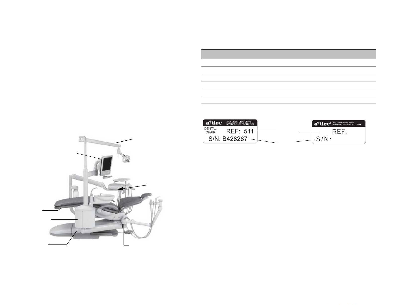
Serial, Model Numbers, Color Identification
Light Location
Chair (Under
Toeboard)
Cuspidor (Inside
Support Center)
Power supply
(inside motor pump area)
Assistant’s
Instrumentation Location
Delivery System
Location
Monitor Mount
Location
Products Manufactured
before June 2011
Serial
Number
Model
Number
Products Manufactured
June 2011 and after
511
11F28293
DENTAL
CHAIR
Serial and Model Numbers
Product serial and model number information can be found on the serial/
model number labels. When contacting customer service, the serial number
helps identify the product and when it was manufactured.
The first letter of the serial number indicates the month the product was
manufactured. For products manufactured before June 2011, the first digit of
the serial number indicates the year of manufacture (for example, L0 =
December 2010). For products manufactured June 2011 and after, the first two
digits indicate the year of manufacture (for example, 11F = June 2011).
Use Table 1 and Figure 2 to reference how to identify serial/model number
information.
Figure 1. Serial/Model Number Locations on A-dec 500
Tab l e 1 . M ont h Ide n tif i c at i o n Tab l e
Letter Month Letter Month
A January G July
B February H August
C March I September
DApril JOctober
EMay KNovember
F June L December
Figure 2. Serial Number Label Examples
86.0348.00 Rev A Introduction 3
Page 12
A-dec 500 and Clinical Products Service Guide Introduction 4
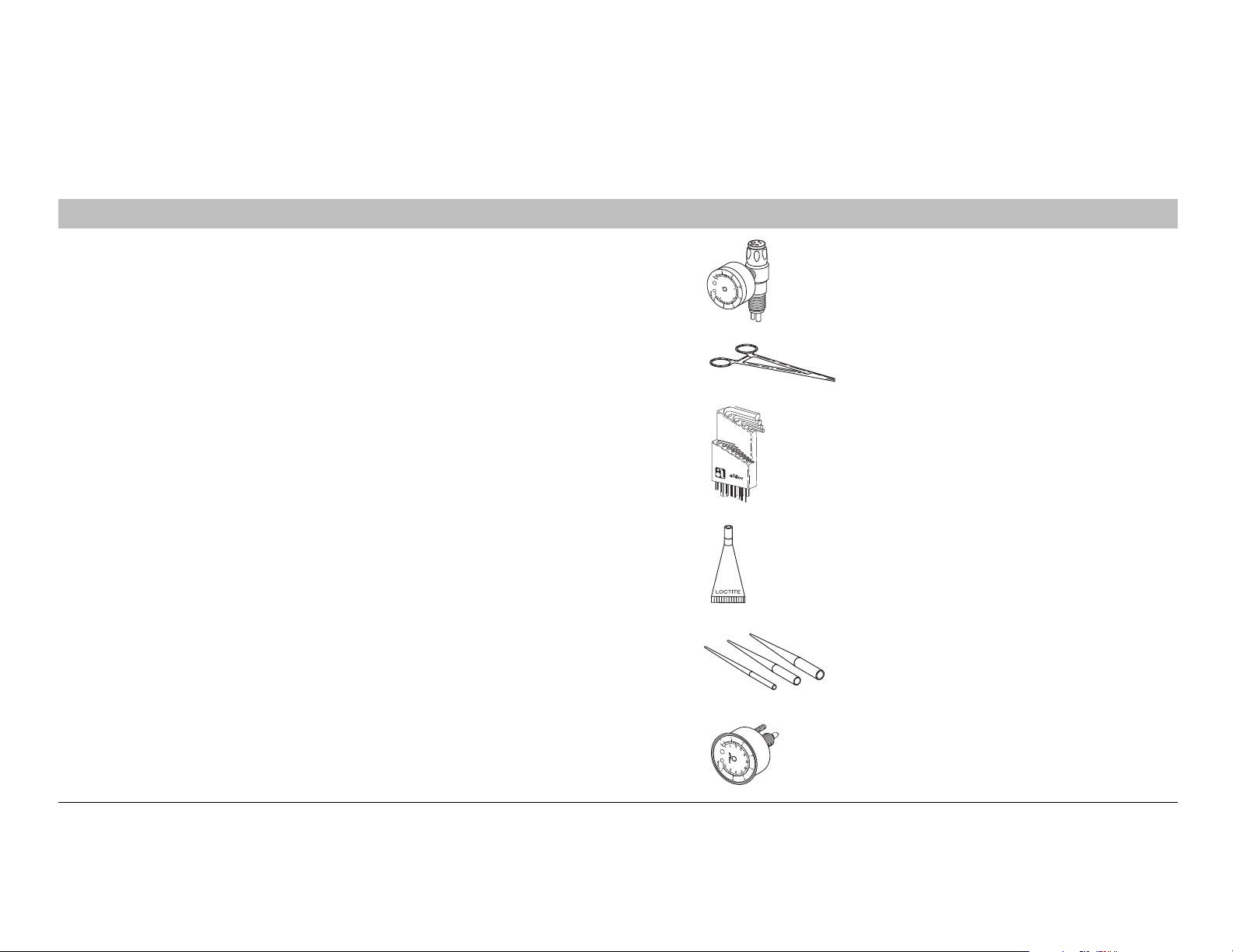
Service Tools
Table 3 lists the types of tools available from A-dec for servicing A-dec equipment and their recommended use:
Figure 3. Recommended Tools
Tool Tas k Part Illustration Part Number
Drive air pressure gauge Adjusting handpiece drive air pressure, 0-60 psi (4 .13 b ar). This
gauge does not fit the Borden 3-hole coupler
Hemostat Troubleshooting or repairing a unit to stop air or water flow
through tubing
Hex wrench or key set Servicing or installing A-dec equipment (plastic case included) 009.018.00
®
Loctite
O-ring tools Replacing O-rings during quick field repairs (fits the four
Installing threaded fasteners to prevent loosening 060.001.00 (Red 271)
smallest O-ring sizes)
50.0271.00
009.008.00
060.002.00 (Blue 242)
009.013.00
Panel mount gauge Checking air/water pressure
Can also be used as an inline pressure gauge for testing
purposes
026.118.00
Page 13
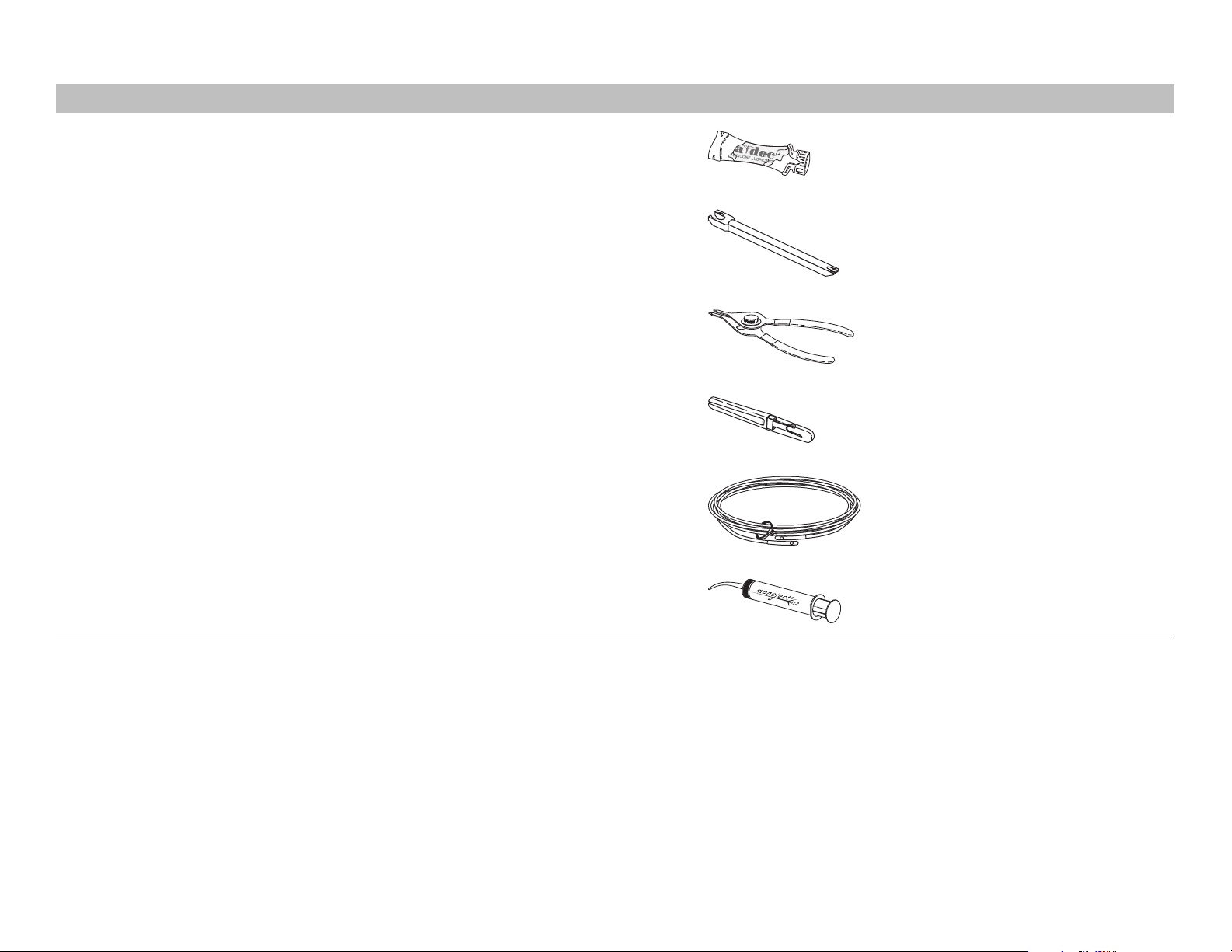
Tool Tas k Part Illustration Part Number
Silicone lubricant Lubrication of internal moving parts such as O-rings, oral
evacuator valves, and bushings
Sleeve tool Aid in securing 1/4" tubing sleeves and 1/8" uni-clamps 98.0072.00
98.0090.01
Snap ring tool Installation and removal of internal and external snap rings (fits
all snap rings used in A-dec equipment)
Tubing stripper Separation of the extruded air and water lines in vinyl tubing 009.035.00
Umbilical stringer Route additional tubing or wiring through existing umbilical
assemblies (12’ [3.66 mm] stringer with threading holes on both
ends)
Valve test syringe Quick tests of pilot operated valves; used to apply a static
pressure of 5-75 psi (.34-5.17 bar, package of 4)
009.007.00
009.015.00
98.0050.01
86.0348.00 Rev A Introduction 5
Page 14

A-dec 500 and Clinical Products Service Guide Introduction 6
Page 15
DENTAL CHAIR
2
This section provides information related to servicing, maintenance, and
adjustments of the A-dec 511 chair. For information on service parts, see the
Genuine A-dec Service Parts Catalog (p/n 85.5000.00) or contact A-dec customer
service.
Contents
• Product Overview, page 8
• Service, Usage, and Adjustments, page 10
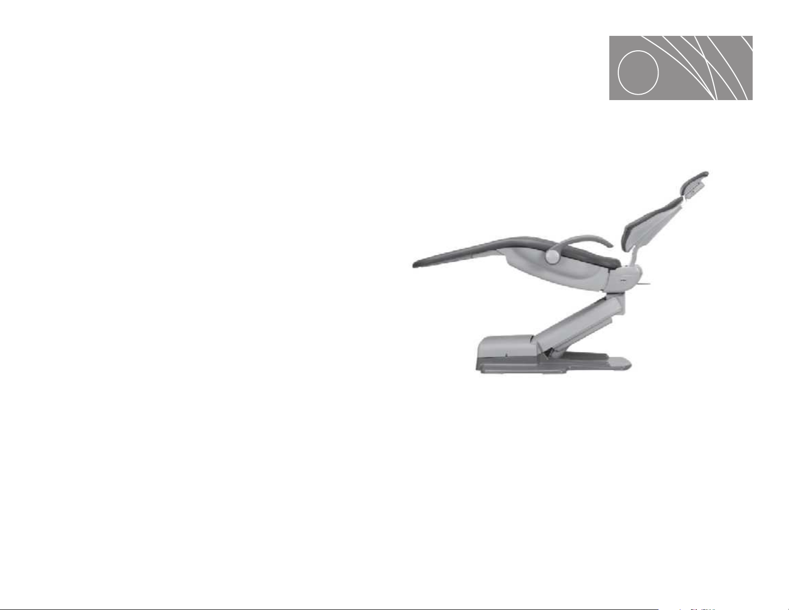
Figure 4. A-dec 511 Dental Chair
86.0348.00 Rev A 7
Page 16
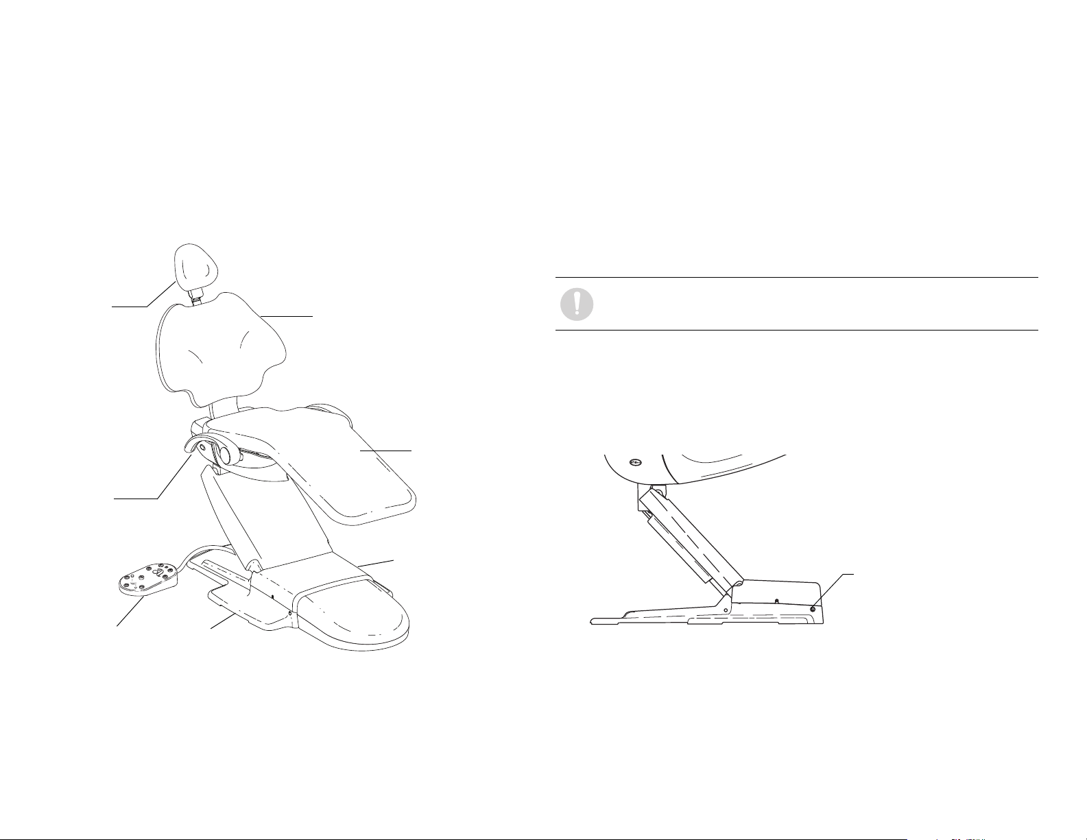
A-dec 500 and Clinical Products Service Guide Dental Chair 8
Hydraulic Motor
Pump Assembly
Baseplate
Armrest
Seat
Headrest
Foot Switch
Back
On/Off Button
Product Overview
A-dec 511 Chair
The A-dec 511 chair provides a range of movements to position the patient for
dental treatment. The chair offers seat and back support, adjustable head
support, and movable arm support, and a footswitch and/or touchpad(s)
control the chair movement.
Figure 5. A-dec 511 Chair Features
A-dec 511 Chair Specifications
Load Capacity
Patient Load: 400 lb. (181 kg) maximum
Accessory Load: 250 lb. (113 kg) maximum
Specifications are subject to change without notice.
NOTE Ensure the chair is bolted to the floor after installation.
Power On/Off Button
The power on/off button is located on the base of the chair, and is the main
disconnect that completely shuts down the electrical systems. When the button
is pressed in, power is on. When the button is out, power is off.
Figure 6. On/Off Button
Limp-Along Feature
If there is a problem or malfunction, the limp-along feature allows the operator
to move the chair in the up direction for one second intervals by pushing the
manual control buttons on the touchpad or footswitch.
Page 17
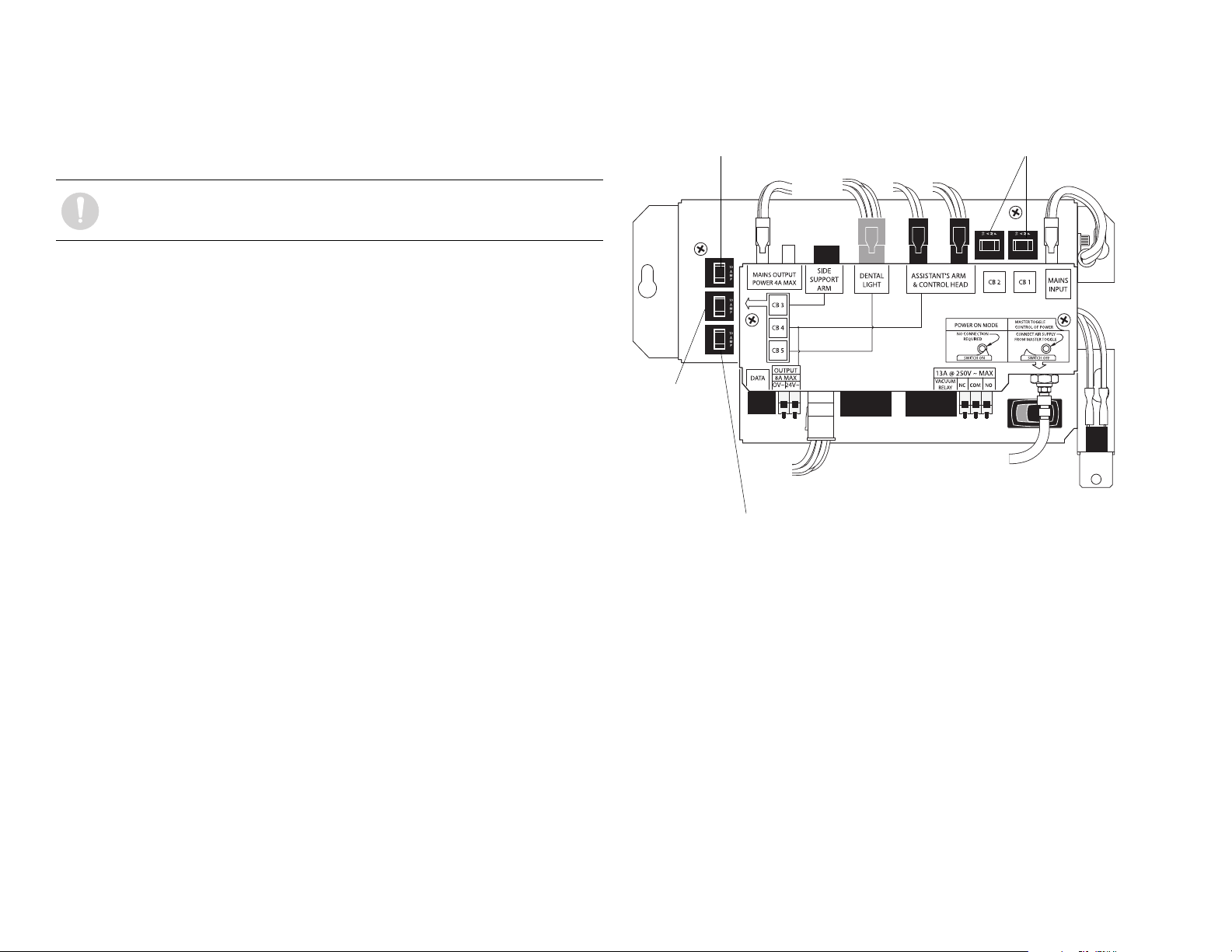
Chair Power Supply
CB 4 Assistant’s
Arm, Control
Head, Chair
Circuit Board.
CB 3 - Support side arm
CB 1 and CB2 - Mains
CB 5 - Dental Light
The 300-watt power supply comes standard with the A-dec 511 chair. It is
located in the motor pump area of the chair. The total available auxiliary load is
a maximum of 4 Amps.
NOTE The electric switch connects the power supply to pilot air.
Figure 7. Chair Power Supply Circuit Breaker Identification
86.0348.00 Rev A Dental Chair 9
Page 18
A-dec 500 and Clinical Products Service Guide Dental Chair 10
Stop Plate
Cover
Lift Arm
Cover
Motor Pump Cover
Motor Pump Cover Plug
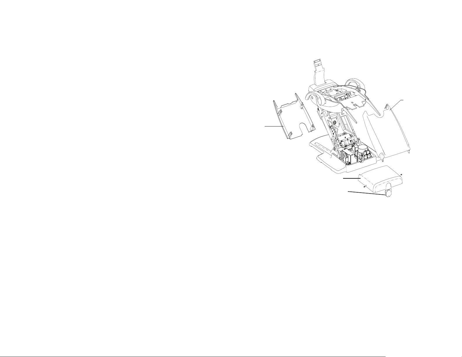
Service, Usage, and Adjustments
Chair Covers
The A-dec 511 chair motor pump, lift arm and stop plate covers are removed in
the following order:
1. Motor Pump Cover
○ To remove: Remove screw from each side and lift up.
○ To replace: Replace cover, and attach with two screws.
2. Lift Arm Cover
○ To remove: Pull one side of the cover until it releases from the lift arm.
○ To replace: Align one side of the cover with the lift arm and snap into
place. Ensure both sides are firmly attached.
3. Stop Plate
○ To remove: Pull one side of the cover until it releases from the lift arm.
○ To replace: Slide one side of the cover over the post on the lift arm and
attach.
Figure 8. A-dec 511 Chair Covers
Page 19

Factory Default Routine
When a new circuit board is installed in the chair, the circuit board needs to run
the factory default routine to learn the range of motion of the chair. The
routine:
• sets the base and back upper limits
• calculates new presets based on actual range of motion of the chair
• verifies that the potentiometers work
To start the factory default routine, place the “spare” jumper in the factory
default position on the P3 test points of the chair circuit board.
When running the factory default routine the chair:
1. Moves base down
2. Moves base up
3. Moves back down
4. Moves back up
5. Moves base and back to Position 0
6. Beeps three times
NOTE The jumper must remain in the factory default position to
complete the factory default routine. The status LEDs on the standard
and deluxe touchpads and the chair circuit board double blink while
the factory default routine is running and after the routine is complete.
86.0348.00 Rev A Dental Chair 11
Page 20

A-dec 500 and Clinical Products Service Guide Dental Chair 12
Chair Circuit Board Components
Part No: 90.1072.00
Item Description
1 P7, P8, P9 - Data line ports
2 DS4 - Stop switch LED (limit switch) and P10 connector
3DS5 - Back potentiometer LED and P1 connector
4 DS6 - Base potentiometer LED and P2 connector
5 P5 - Footswitch connector
6P3 - Test points
7DS12 - Base down LED and relay K5
8 DS11 - Base up LED and relay K4
9 DS10 - Back down LED and relay K3
10 DS9 - Back up LED and relay K2
11 DS1 - AC power LED
12 DS2 - Stat us LED
13 DS3 - Data LED
14 DS13 - Chair lockout LED and terminal strip J1
15 J2 - Ø VAC terminal strip (output)
16 J2 - 24VAC terminal strip (outp ut)
17 P4 - Input power and dental light connector
18 J3 - Vacuum relay K7 and output terminal strip
19 P11 - Pump motor and solenoid connector
20 DS8 - Dental light LED and relay K1
21 DS7 - Dental light LED and relay K6
Page 21
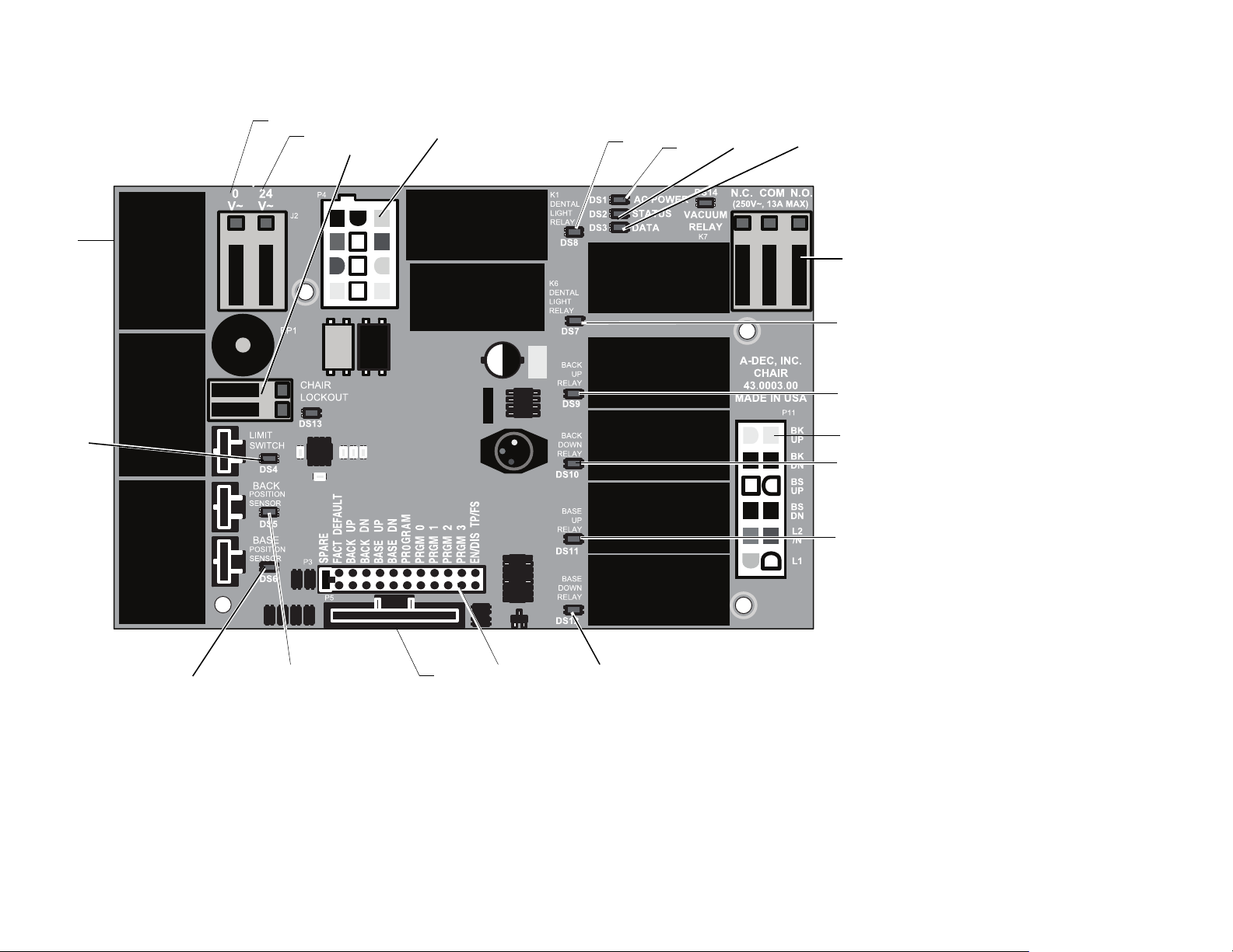
Figure 9. A-dec 511 Chair Circuit Board Components
1
11
12
13
14
4
3
5
67
8
9
10
21
18
16
15
17
20
2
19
86.0348.00 Rev A Dental Chair 13
Page 22

A-dec 500 and Clinical Products Service Guide Dental Chair 14
LED Identification
This table describes the LEDs on the chair circuit board.
Figure 10. LED Identification Table
LED Status Description
DS1 - AC power LED Off No 24 VAC power, tripped circuit breaker, power supply turned off, no line voltage
Green, steady 24VAC at the terminal strip
DS2 - Status LED Off System is not functioning, no power or circuit board has failed
Green, steady Normal operation
DS3 - Data LED Off No DCS communication, not connected to the DCS, or DCS has failed
Green, steady Detects active DCS
Green, blinking Valid DCS Message
DS4 - Chair limit switch Off Closed, (normal)
Red Open, (activated)
DS13 - Chair lockout Off Open, (normal)
Red Closed, (activated)
DS5 + DS6 - Chair potentiometers Off Potentiometer:
• Not connected or bad connection
• Moving in wrong direction
• Limited range of mot io n, or
•Cable is not on wheel
Yellow, steady Normal operation
Yellow, fast blink Upper end of travel
DS9, DS10, DS11, DS12 - Chair relay LEDs Off Relay is off
On Relay is on
DS7, DS8 - Dental light relay LEDs Off Relay is off
On Relay is on
DS14 - Vacuum relay LED Off Relay is off
On Relay is on
Page 23
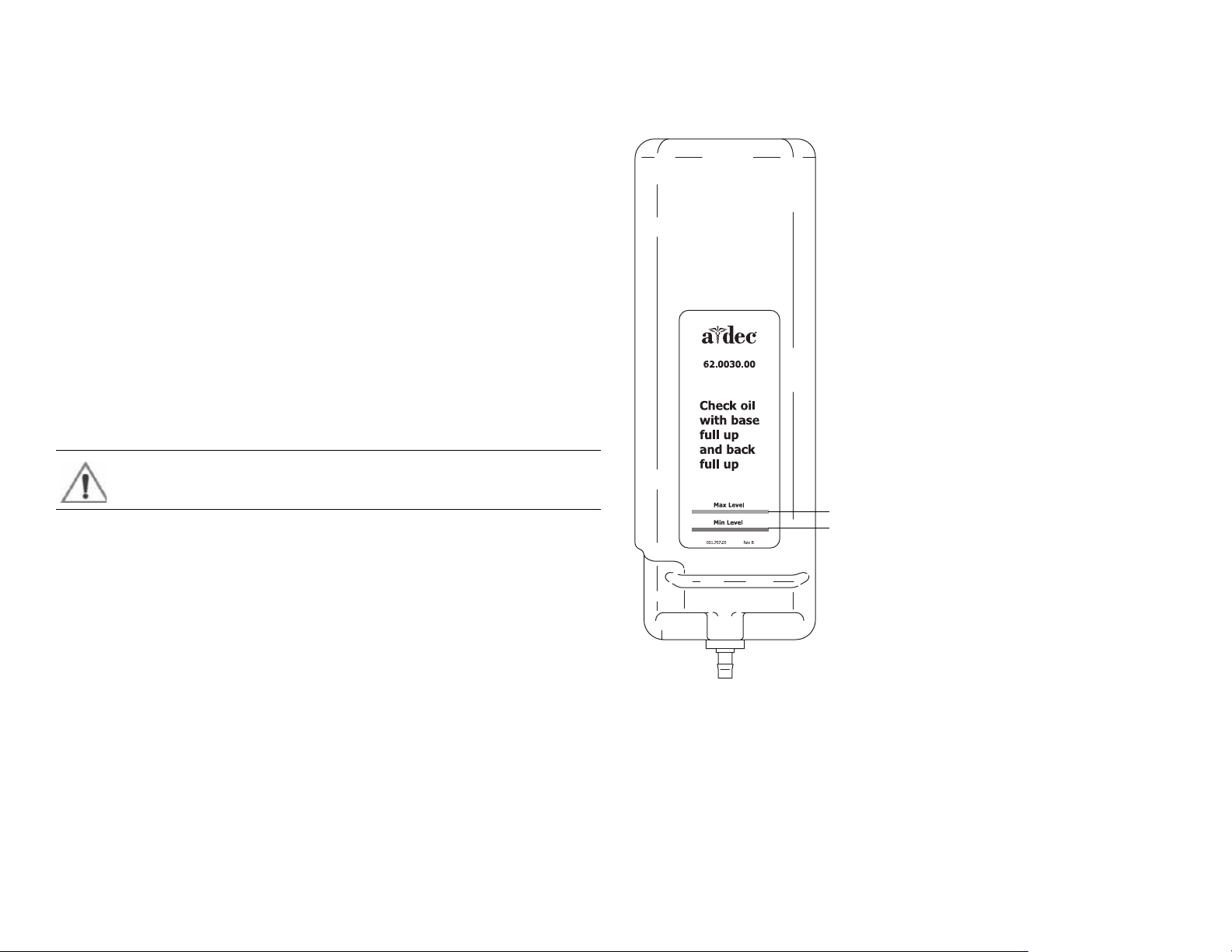
The Hydraulic System
Max Level
Min Level
The hydraulic system deactivates automatically at the upper and lower
extremes of travel. The system is leak-free during transportation, storage, and
operation. The hydraulic system consists of:
• Hydraulic fluid reservoir
•Hydraulic cylinders
• Motor-driven hydraulic pump with solenoids
Hydraulic Fluid Reservoir
The hydraulic fluid reservoir is located in the lift arm of the chair under the
stop plate cover. You can see the fluid level in the reservoir through the sides of
the reservoir. A top fill cap allows you to add fluid. The hydraulic system holds
40 ounces (2.5 pints [1.18 l]) of hydraulic fluid. To fill the reservoir:
1. Place the chair in the full base and back up position.
2. Fill to the green Max line. See Figure 11.
CAUTION Do not overfill.
3. Cycle the chair after the reservoir is filled.
Figure 11. Hydraulic Fluid Reservoir
86.0348.00 Rev A Dental Chair 15
Page 24
A-dec 500 and Clinical Products Service Guide Dental Chair 16
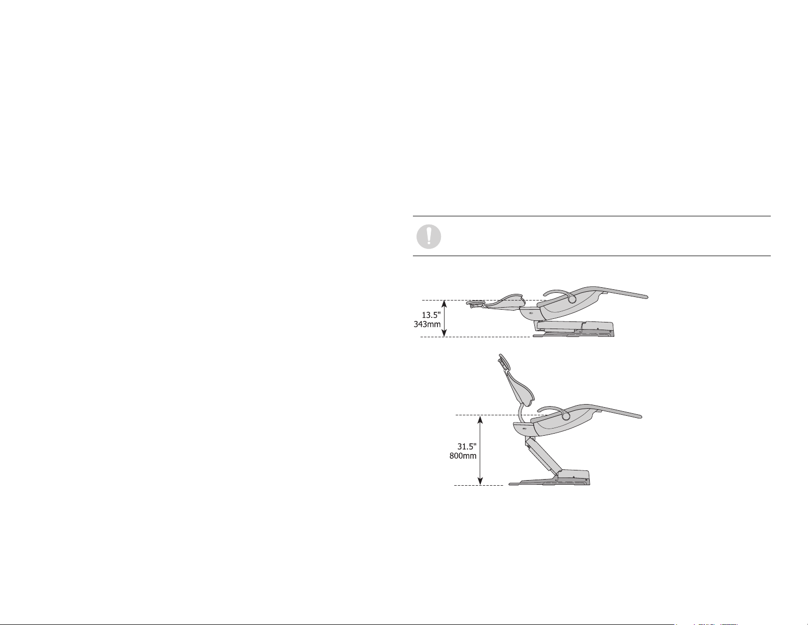
Hydraulic Cylinders
The hydraulic cylinders operate during the Base Up and Back Up functions.
Springs and gravity retract the piston during Base Down and Back Down
functions.
The chair seat travels vertically from a low point of 13.5" (343 mm) to a high
point of 31.5" (800 mm) above the floor. See Figure 12.
Motor Driven Hydraulic Pump
The hydraulic pump takes hydraulic fluid from the reservoir and pressurizes it
to extend the chair lift and tilt hydraulic cylinders for back and base up
functions. The bi-directional pump rotates one direction for Base Up and the
opposite direction for Back Up.
The solenoids mounted to the pump assembly gate hydraulic fluid from the
two cylinders. Depending on the chair Down function, the controller selects
which solenoid-actuated manifold valves are open or closed. The 100-120 VAC
pump and 220-240 VAC pump are equipped with an automatic reset 110°C
(230°F) thermal limiter. There are no serviceable parts on the hydraulic pump
other than the solenoids.
NOTE You cannot adjust the speed of the chair.
Figure 12. Hydraulic Cylinder Operation
Page 25
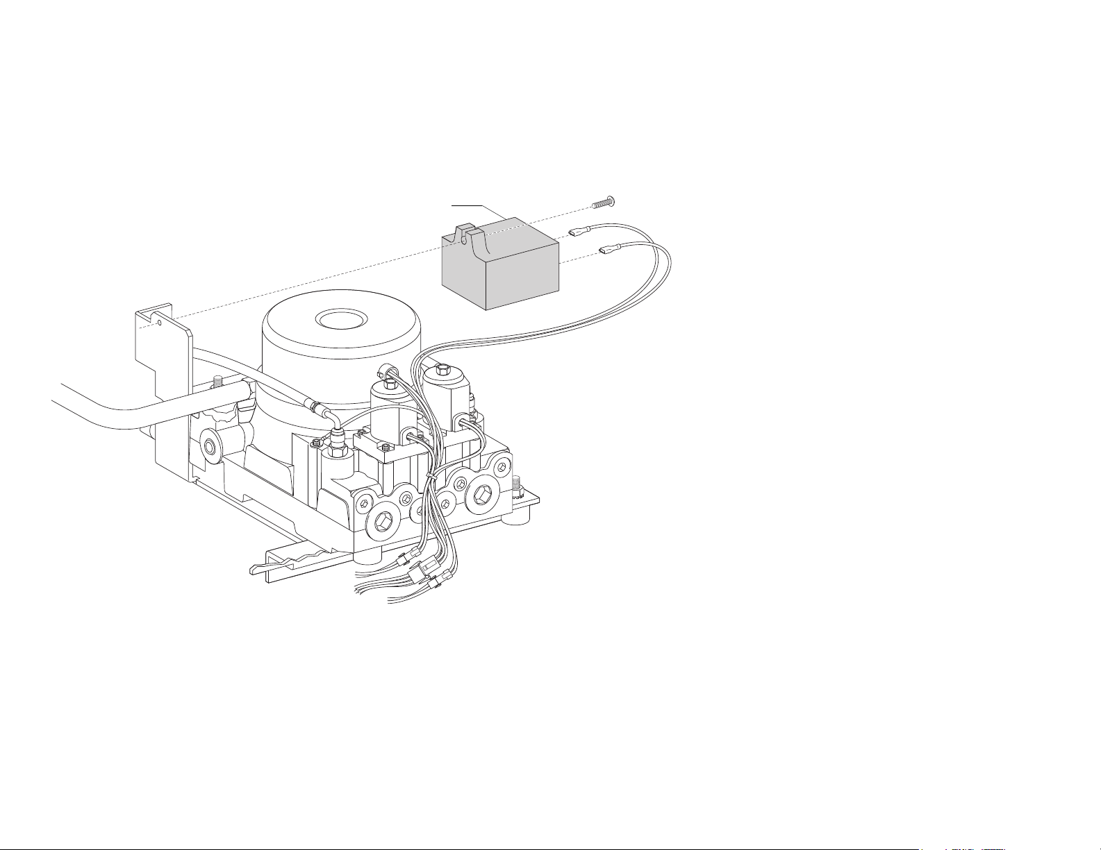
Capacitor
Capacitor
Part Number: 041.642.00, 100 VAC, 041.643.00, 110 - 120 VAC, 041.644.00, 220 - 240 VAC
The capacitor is energized during chair Base Up or Back Up functions.
Figure 13. A-dec 511 Chair Capacitor
86.0348.00 Rev A Dental Chair 17
Page 26
A-dec 500 and Clinical Products Service Guide Dental Chair 18
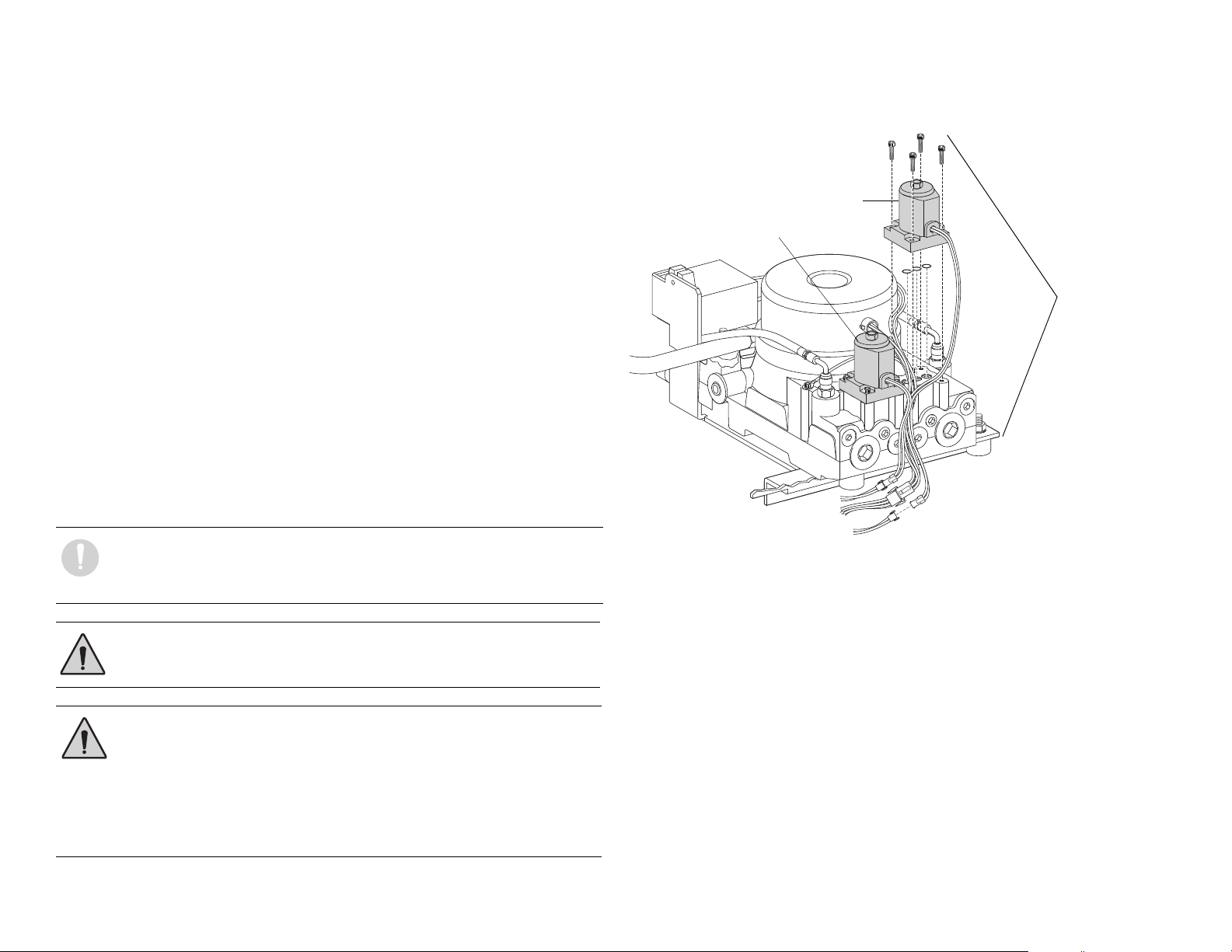
Solenoids
Part No: 90.1070.00, 110 - 120 VAC, 90.1071.00, 220 - 240 VAC
Figure 14. A-dec 511 Chair Solenoids
Test Solenoids
A solenoid is entergized during Base Down and Back Down functions. To
check for a failed solenoid, test the solenoids using a volt/ohm meter or
Back Down Solenoid
magnetic pull test:
Base Down Solenoid
Magnetic Pull
1. Hold a paper clip loosely in your hand.
2. Activate the solenoid by pressing Base Down or Back Down on the
footswitch or touchpad.
3. If there is a pull on the paper clip, the solenoid is being entergized.
Coil Resistance
Disconnect the solenoid power at the 2-position connector. Place on Ohm meter
probe on each solenoid connector terminals.
• 100 - 120 VAC = 177 Ohms ± 18 Ohms
• 220 - 240 VAC = 845 Ohms ± 85 Ohms
NOTE If the solenoid is hot, then the resistance reads higher.
NOTE When replacing a solenoid, wipe up any oil, and replace
existing O-rings on the solenoid base.
WARNING The solenoid coils are powered by line voltage (100, 120, or
240 VAC). Failure to unplug the chair may result in serious injury
from electrical shock.
WARNING You must depressurize the base or back system prior to
removing the solenoid.
Motor Pump
Assembly
1. Depressurize base or back system.
2. Remove the failed solenoid coil.
3. Replace with the operating solenoid coil.
4. Lower the chair base and back.
Page 27
Potentiometer
Base Up Potentiomete
Back Up Potentiometer
The potentiometer and cable assembly is a simple, accurate unit, which eliminates position float. “Float” is a slight change or variation in the pre-programmed
positions. The chair uses the same potentiometer assembly for both lift and tilt requirements. If a potentiometer should fail, the limp-along feature allows the
operator to position the chair for one second intervals by pushing the manual control buttons on the touchpad or footswitch.
Figure 15. Location of Chair Base Up and Back Up Potentiometers
86.0348.00 Rev A Dental Chair 19
Page 28
A-dec 500 and Clinical Products Service Guide Dental Chair 20
Stop Switch
Assembly
Chair Stop Plate
The chair stop switch stops chair movement when you press the stop plate.
Should anything inadvertently become lodged under the chair, press Base Up
on the touchpad or footswitch to raise the chair so you can remove the object.
As long as you apply pressure to the stop plate, the chair does not move down.
The stop plate has only one switch. The switch and all other parts snap into
place for easy removal or replacement. No tools are required.
WARNING Be sure to power off the chair and disconnect it from its
power source before replacing the stop switch.
CAUTION Cable tie the wires to the lift arm to prevent kinking and
pinching.
Chair Bump-Up Feature
The chair stop plate and the assistant’s arm trigger the chair to move upwards
if it was moving down when the stop plate switch was activated.
Figure 16. A-dec 511 Chair Stop Plate
Page 29
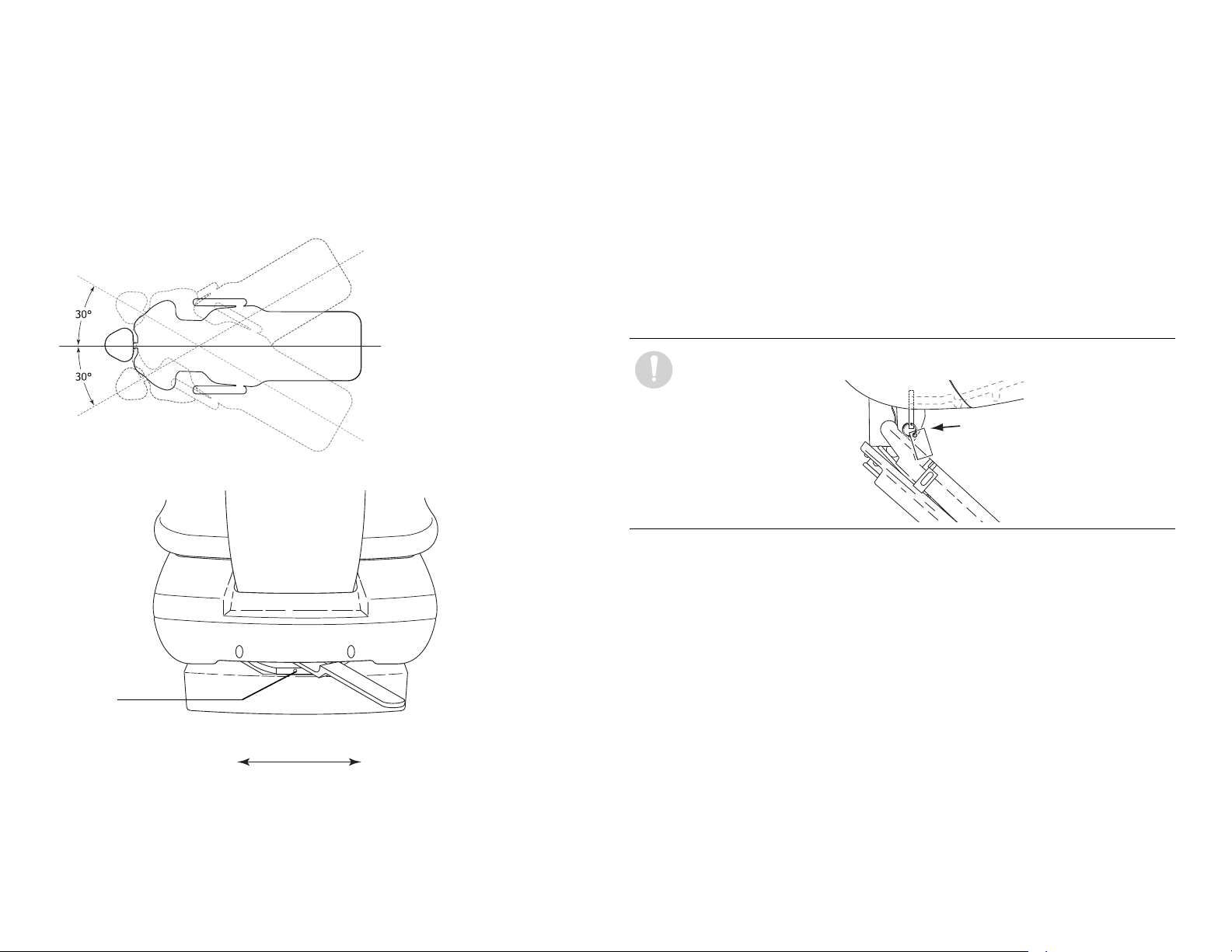
Swivel Brake Adjustment
The chair can rotate to any position within 30° either side of center. The chair
swivel brake keeps the chair from moving. To engage the brake, push the brake
lever firmly to the left. To release the swivel brake, push the brake lever to the
right.
Figure 17. Chair Swivel
Figure 18. Swivel Brake Tension Adjustment
Tension Adjustment
If the chair swivels left or right with the brake engaged or if it is difficult to
move with the brake disengaged, adjust the swivel brake tension. To adjust the
tension, use a 5/32 hex key and turn the tension adjustment screw;
• Clockwise to increase brake friction.
• Counterclockwise to decrease brake friction.
If you cannot obtain proper adjustment through rotation of the hex key, replace
the brass brake pad by removing the brake handle and using a hex key to
disengage the pad. Remove the old pad and replace with new one. Replace the
brake handle and handle retainer.
NOTE To disable the swivel feature, reinstall the shipping pin.
Tension
Adjustment Screw
Engaged
86.0348.00 Rev A Dental Chair 21
Released
Page 30
A-dec 500 and Clinical Products Service Guide Dental Chair 22
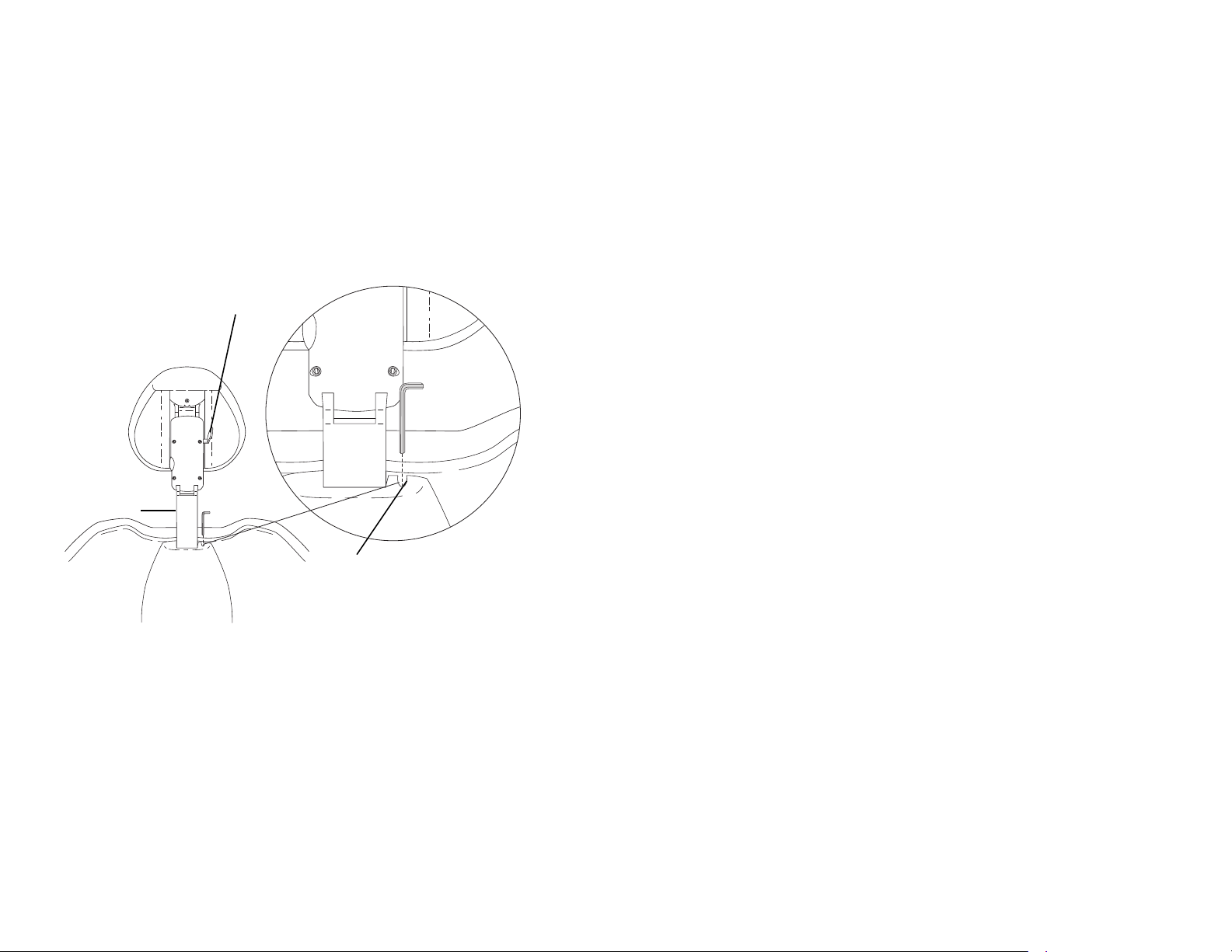
Glide Bar
Headrest Adjustment Lever
Glide Bar Tension Adjustment
Headrest Adjustment
The headrest adjustment lever allows you to use one hand to adjust the
headrest. When the lever is released, the headrest holds its position.
If the headrest drifts downward, or if it is difficult to move up or down, adjust
the glide bar tension. To adjust the tension, use a 1/8 hex key and turn the
tension adjustment screw clockwise to increase friction or counterclockwise to
decrease friction.
Figure 19. Headrest Adjustments
Page 31

PROGRAMMING
Standard Surf
Standard White
Deluxe Surf
Deluxe White
Note: Touchpad symbols are proprietary to A-dec Inc.
3
The A-dec 500 touchpad centralizes treatment room controls into one touch
surface. The standard touchpad controls the chair, cuspidor, and dental light
functions. The deluxe touchpad adds controls for the handpieces, electric
motors, and other options.
For information on service parts, see the Genuine A-dec Service Parts Catalog
(p/n 85.5000.00) or contact A-dec customer service.
Programming Contents
• Status Icon, page 24
• Chair Positioning, page 24
•Cuspidor Functions, page 26
• Dental Light, page 27
• Electric Handpiece Settings (Deluxe Touchpad Only), page 28
• Technician Setup Options, page 32
• Touchpad Circuit Board Components, page 37
Figure 20. Standard and Deluxe Touchpads
86.0348.00 Rev A 23
Page 32

A-dec 500 and Clinical Products Service Guide Programming 24
Status Icon
Or
Or
Or
Or
Or
Or
Or
Or
Status Icon
The A-dec logo indicates the system status.
• Solid blue—normal operation and power is on.
• Blinking— chair stop plate or cuspidor limit switch is active. The icon
returns to solid blue once you remove any obstructions.
• Double blink —jumper is on the factory default position on the chair circuit
board. The icon returns to solid blue once the jumper is removed.
Figure 21. Status Icon
Chair Positioning
Your touchpad provides manual and programmed controls for A-dec chair
positioning. The direction arrows on the touchpad allow you to manually move
the chair base and back up or down.
Table 2. Manual Chair Buttons
Position Buttons
Chair position buttons are factory preset to automatically move the chair. Four
programmable chair buttons, which can be easily customized, automatically
move the chair into a factory preset position.
Table 3. Programmable Chair Buttons /Factory Presets
Button Position Description
Entry/Exit: Automatically positions chair for entry/exit and
turns off dental light.
Treat m e n t 1 : Automatically positions the chair base and back
down and turns on the dental light.
Treat m e n t 2 : (Standard touchpad only): Automatically positions
the chair base and back and turns on the dental light.
X-ray/Rinse: Automatically positions the chair for either x-ray
or rinse. Toggles between the x-ray/rinse and the last manual
position, and turns off the dental light.
Icon Action
Back down
Base down
Back up
Base up
Page 33

Program Chair Preset Positions
A
B
C
Standard Surf
Standard White
To program Entry/Exit, Treatment 1, and Treatment 2 buttons:
1. Use the manual buttons to move the chair into the desired position.
Customize the X-Ray/Rinse Button
The X-ray/Rinse button functions either as x-ray/rinse or as another preset
position (Treatment 3). To change the function:
2. Press and release the program button ( or ). One beep indicates
programming mode.
3. Press the chair position you want to program (for example or for
entry/exit). Three beeps indicate the button has been set.
Figure 22. Touchpad Chair Position Buttons
(A) Manual Chair Buttons; (B) Program Buttons; (C) Programmable Chair Buttons
1. Press and hold the program button ( or ) and or at the
same time for three seconds.
○ One beep indicates the button has been configured as Treatment 3.
○ Three beeps indicate that the X-ray/Rinse button has been configured as
the x-ray/rinse function (toggles between the x-ray/rinse and the
previous position).
2. Program the preset position as instructed under "Program Chair Preset
Positions."
NOTE If the X-Ray/Rinse button is changed to a preset position, it
operates the same as Treatment buttons 1 and 2.
86.0348.00 Rev A Programming 25
Page 34

A-dec 500 and Clinical Products Service Guide Programming 26
or
or
Cuspidor Functions
Cupfill
The cupfill function controls water flow from the cuspidor into a cup.
Figure 23. Cupfill and Bowl Rinse Buttons
Button Description
Cupfill Button: Controls water flow from the cuspidor into a cup.
• Press the cupfill button for a timed operation. The factory preset
is a 2.5 second fill.
• Press and hold the cupfill butt on for manual operation.
Bowl Rinse Button: Provides rinse water for the cuspidor bowl.
• Press the bowl rinse button for a timed operation. The factory
preset is a 30 second rinse.
• Press and hold the bowl rinse button for manual operation.
TIP Press the bowl rinse button twice in less than two seconds to
activate the continuous operation mode. Press the button once to end
the continuous bowl rinse mode.
Customize Cupfill and Bowl Rinse
To program the cupfill and bowl rinse timing:
1. Press and release the Program button ( or ), or at the cuspidor
press and hold both the cupfill and bow rinse buttons located near the
spout. One beep indicates programming mode.
2. Press and hold the cupfill or bowl rinse button for the desired time.
3. Release the button. Three beeps confirm the setting.
NOTE Cupfill and bowl rinse functions are not available on standard
touchpads that use auxiliary buttons ( or ) along with
an A-dec relay module. In this case, use the cuspidor-mounted buttons
or the deluxe touchpad to control automated cuspidor functions.
Page 35

Dental Light
The dental light button on the touchpad allows you to turn the dental light on
or off, and change intensity. You can turn the dental light on or off from either
the touchpad or the dental light.
Figure 24. Dental Light Button
Button Description
Dental Light Button: Functions as a three-way on/off switch and
toggles between intensity settings.
Press to toggle between high and composite or medium and composite.
When the dental light is in composite mode, the indicator light next to the
button blinks. See Figure 25. Press and hold for one second to turn the
dental light off.
Figure 25. Dental Light Composite Mode
Indicator Light
Dental Light Auto Feature
The dental light has an auto on/off feature. When you use a programmed chair
position, the dental light turns on when the chair reaches operating position.
Press Entry/Exit ( or ) or X-ray/rinse ( or ) and the dental light
automatically turns off.
NOTE If the X-ray/Rinse button is changed to a preset position, the
dental light auto feature operates the same as Treatment buttons
1 and 2.
To activate/deactivate:
Press and hold the light ( ) and the program ( or ) buttons at the
same time for three seconds. One beep confirms the dental light auto feature is
off.
A and B Buttons
Deluxe touchpads include an A/B button ( ) that offers two separate sets of
programmable settings. The currently active set is indicated by the A or B in the
touchpad display. See Figure 26.
Figure 26. A/B Selection
86.0348.00 Rev A Programming 27
Page 36

A-dec 500 and Clinical Products Service Guide Programming 28
Electric Handpiece Settings (Deluxe Touchpad Only)
Standard Mode Programming
Activate the electric motor by lifting the handpiece from the holder. The
settings that appear are the ones last used for that handpiece position. This
table lists the factory presets for electric handpieces:
Table 4. Electric Motor Presets (Standard Mode)
Memory Button Preset Speed Air Coolant Water Coolant
M1 2,000 RPM on on
M2 10,000 RPM on on
M3 20,000 RPM on on
M4 36,000 RPM on on
The A-dec Deluxe touchpad allows you to program four memory buttons with
your specific RPM setting. The total range is 300 - 36,000 RPM. With the A/B
button, you can program two settings for each memory button, for a total of 8
customized settings per handpiece (the endodontic mode offers an additional 8
memory settings).
NOTE If two operators use the delivery system, be sure to select the
correct operator set (A or B) before changing any memory settings.
The currently active set is indicated by the A or B in the touchpad
display. See Figure 27 on page 29.
To program the handpiece setting:
1. Lift the handpiece from the holder.
2. If the touchpad screen does not display standard mode, press the
Endodontics Mode Toggle button.
3. Press the minus (-) and plus (+) buttons to adjust the RPM. The RPM values
are displayed in the display screen. See Figure 27.
4. If desired, use the toggle buttons on the touchpad to change air and water
settings.
5. To place the setting into memory, press the program button ( or ).
One beep sounds.
6. Select the desired memory setting (m1, m2, m3, or m4). Three beeps confirm
the setting.
Page 37

Standard Mode Display Settings
A
H
J
K
L
M
B
C
E
G
D
F
Figure 27. Program Handpiece Standard Mode Settings
Item Description Item Description
A Memory Setting Indicator G Water Coolant Button
B Water Coolant Indicator H Air Coolant Button
CAir Coolant Indicator J Speed Limit Setting
D A/B Operator Indicator K Forward/Reverse Indicator
E Memory Buttons (m1 - m4) L Forward/Reverse Toggle Button
F Program Button M Adjustment Buttons
Forward/Reverse Button
The Forward/Reverse toggle button changes the electric motor’s direction. The
system defaults to the forward position when you return the handpiece to the
holder or turn off the system. In reverse mode, the screen indicator flashes
continuously.
NOTE You can also use the foot control as a forward/reverse toggle.
When the motor has stopped, tap the accessory (chip/air) button to
change the direction.
86.0348.00 Rev A Programming 29
Page 38

A-dec 500 and Clinical Products Service Guide Programming 30
Endodontics Mode
Endodontics mode allows you to change a number of settings based on the
specific file and desired handpiece behavior.
NOTE For more information regarding speed limit and torque limit
for a specific file, consult the file manufacturer.
Figure 28. Endodontics Mode Touchpad Screen (Deluxe Surf Shown)
A
B
C
L
D
E
G
H
J
K
M
N
To program the endodontics memory settings:
1. Lift the handpiece from the holder.
2. If the touchpad window is not in endodontics mode, press the Endodontics
Mode Toggle button. The endodontics screen is displayed.
3. Press the plus (+) or minus (-) button to activate the endodontics change
mode. A white reverse video box appears.
4. Use the chair positioning buttons to move from setting to setting in the
touchpad window.
5. Use the + and - buttons to change the setting as desired.
6. To place the speed limit, torque limit and ratio into memory (optional),
press the program button ( or ), then the memory button you want to
set. Three beeps confirm the setting.
F
Item Description Item Description
A Memory Setting Indicator J Handpiece Light Indicator
B Water Coolant Indicator K File Torque Unit Indicator
C Air Coolant Indicator L File Torque Limit
D Operator Status Indicator M Forward/Reverse Indicator
E Memory Button N Torque Mode Indicator
F Endodontics Mode Toggle Button O Handpiece Ratio Setting
G File Speed Setting P Forward/Reverse Toggle Button
H Warning Beep Indicator
O
P
Page 39

Endodontics Mode Settings
This table lists and defines the touchpad window icons for endodontics mode.
Figure 29. Endodontics Mode Settings
Icon Setting Description
Speed Setpoint for file speed limit. For more information, consult your
file manufacturer.
Torque Setpoint for file torque limit. For more information, consult your
file manufacturer.
Torque
Units
Ratio Sets the handpiece ratio. For more information, consult your
Air
Coolant
Toggles between Ncm (Newton centimeters) and gcm (Gram
centimeters). Adjusting this setting for one handpiece changes it
for all handpiece settings.
1 Ncm=102 gcm
handpiece manufacturer.
On/Off—when active, supplies air coolant to the handpiece.
NOTE The A-dec/W&H WD-79M endodontics attachment has a
special feature due to its ball-bearing design. Its life-long efficiency
factor is stable and known, therefore the A-dec endodontics system is
able to control and display file torque very accurately. All other
handpieces have unknown life-long efficiency factors and therefore
stated torque values are approximate.
Water
Coolant
Light
Source
Torque
Mode
Auto off
Auto
reverse
Auto
forward
Beeper On/Off—when active, warning beep sounds when you approach
86.0348.00 Rev A Programming 31
On/Off—when active, supplies water coolant to the handpiece.
Enables/disables endodontics hand piece light source.
Adjusting this setting for one handpiece changes it for all
handpiece settings. This icon appears with the forward/reverse
indicator.
Auto-off—the motor stops when t he file speed reac hes the torque
limit.
Auto-reverse—the motor stops and reverses direction when the
file reaches the torque limit.
Auto-forward—when the file reaches the torque limit, the motor
stops, reverses 3 turns, then changes back to forward again.
Note: If the file is stuck, this cycle repeats three times before
the motor stops.
torque limit and double beeps when the file auto-reverses.
Adjusting this setting for one handpiece changes it for all
handpiece positions.
Page 40

A-dec 500 and Clinical Products Service Guide Programming 32
Technician Setup Options
The deluxe touchpad allows service technician access to adjust handpiece and
touchpad settings for user preferences.
Using Touchpad Buttons for Navigation
Chair button functions become navigation buttons while you are in setup
mode. You will use the back up (
down (
) buttons to navigate the setup screens.
) back down () base up () and base
Holder Setup
You can set up how handpieces are configured for each handpiece holder.
To set up handpiece holders:
1. From the deluxe touchpad main screen, press and hold the A/B ( ) and
Program ( or ) buttons at the same time for three seconds; then
to begin. You see the System Setup screen.
press
2. Press the
SYSTEM SETUP
Handpieces
Touchpad
= BACK = SELECT
= MOVE
or to select Handpieces, and press .
5. Press
. Three beeps confirm the setup for the handpiece is complete.
6. Return the handpiece to the holder.
7. Repeat steps 4 through 7 to set up each handpiece.
8. When you are finished setting up handpieces, press
A-dec logo.
until you see the
3. From the Handpiece Setup screen, press
Setup, and press
HANDPIECE SETUP
Holder Setup
Electric Setup
Ultrasonic Setup
Intraoral Lt Source
= BACK = SELECT
= MOVE
.
4. Lift the desired handpiece from the holder.
or to select to select Holder
Page 41

Electric Options Setup
HANDPIECE SETUP
= BACK = SELECT
= MOVE
Holder Setup
Electric Setup
Intraoral Lt Source
Ultrasonic Setup
You can change display information and how the functions operate with the
electric motor. The following options are available:
• Torque Units: Select how to display the units, either Ncm (Newtons per
centimeters) or gcm (gram per centimeters).
• Endo Handpiece Auto Mode: Configure how the electric motor reacts when
the torque limit is reached.
○ Auto Forward: Motor will stop, reverse three turns, and return forward
again.
○ Auto Reverse: Motor will reverse.
○ Auto Stop: Motor will stop.
3. From the Handpiece Setup screen, press
Setup, and press
4. From the Electric Setup screen, press minus (-) or plus (+) to highlight an
option, such as Torque Units, and press
.
or to select to select Electric
.
• Auto Reverse Beep: Enable to hear two beeps when the motor exceeds its
torque threshold and automatically reverses direction.
• Torque Warning: Enable to hear a continuous beep when the motor exceeds
75% of the torque threshold.
To set up electric options:
1. From the deluxe touchpad main screen, press and hold the A/B ( ) and
Program ( or ) buttons at the same time for three seconds; then press
to begin. You see the System Setup screen.
2. Press the
or to select Handpieces, and press .
SYSTEM SETUP
Handpieces
Touchpad
= BACK = SELECT
= MOVE
ELECTRIC SETUP
Torque Units
Torque Warn Beep
Auto Rev Beep
Auto Mode
= BACK -/+ = CHANGE
= MOVE
5. Specify other electric handpiece options by pressing minus (-), plus (+), and
to move through the screens. Once the setup is complete, three beeps
confirm the setting for all handpieces.
6. When all settings are complete, press
= SELECT
gcm
ON
ON
Stop
until you see the A-dec logo.
86.0348.00 Rev A Programming 33
Page 42

A-dec 500 and Clinical Products Service Guide Programming 34
ULTRASONIC SETUP
= BACK +/- = CHANGE
= MOVE
Acteon Colors OFF
= SAVE
Ultrasonic Setup
You can select whether to turn on or off the ultrasonic colors.
To set up ultrasonic colors:
1. From the deluxe touchpad main screen, press and hold the A/B ( ) and
Program ( or ) buttons at the same time for three seconds; then press
to begin. You see the System Setup screen.
2. Press the
or to select Handpieces, and press .
SYSTEM SETUP
Handpieces
Touchpad
= BACK = SELECT
= MOVE
4. Press minus (-) or plus (+) to display On or Off, and press
confirm the setting has been programmed.
5. Press
until you see the A-dec logo.
. Three beeps
3. From the Handpiece Setup screen, press
Setup, and press
HANDPIECE SETUP
Holder Setup
Electric Setup
Ultrasonic Setup
Intraoral Lt Source
= BACK = SELECT
= MOVE
or to select to select Ultrasonic
.
Page 43

Light Source Setup
HANDPIECE SETUP
= BACK = SELECT
= MOVE
Holder Setup
Electric Setup
Intraoral Lt Source
Ultrasonic Setup
LT SOURCE SETUP
On When Sel
Press -/+ to change
<Back
Select>
The following light source options are available:
• On When Selected: Specify whether the intraoral light source turns on or
remains off when the handpiece is removed from the holder.
• Auto Off Delay: Determine how long the light remains on when the foot
control is released. This time is reset when you use the drive air again or
replace and pick up the handpiece. The factory setting is five seconds.
• On in Endo: Specify whether the intraoral light source turns on or off when
in endodontics mode. Because most endodontics handpieces do not have
light pipes, it is recommended that Off is selected to reduce heat and to
extend bulb life.
To set up the light source:
1. From the deluxe touchpad main screen, press and hold the A/B ( ) and
Program ( or ) buttons at the same time for three seconds; then press
to begin. You see the System Setup screen.
2. Press the
or to select Handpieces, and press .
SYSTEM SETUP
Handpieces
Touchpad
4. Lift the desired handpiece from the holder.
5. From the Light Source Setup screen, withdraw the desired handpiece from
the holder and press
6. From the Light Source Setup screen, press minus (-) or plus (+) to select the
desired option, for example, On When Selected, and press
.
.
LIGHT SOURCE SETUP
On When Selected ON
On In Endo OFF
Auto O Delay 15
= BACK -/+ = CHANGE
= MOVE = SAVE
7. Specify other light source options for the handpiece by pressing minus (-),
plus (+), and
three beeps confirm the setting.
8. Return the handpiece to the holder.
9. Repeat steps 3 through 7 to configure each handpiece.
10.When you are finished setting up handpieces, press
A-dec logo.
to move through the screens. Once the setup is complete,
until you see the
= BACK = SELECT
= MOVE
3. From the Handpiece Setup screen, press
Lt Source, and press
86.0348.00 Rev A Programming 35
or to select to select Intraoral
.
Page 44

A-dec 500 and Clinical Products Service Guide Programming 36
TOUCHPAD SETUP
= BACK = SELECT
= MOVE
Contrast Adjust
Help Messages
CONTRAST ADJUST
= BACK -/+ = CHANGE
21
of 63
= SAVE
HELP MESSAGES
= BACK -/+ = CHANGE
OFF
= SAVE
Touchpad Setup
Use the touchpad setup to change the contrast of the touchpad screen display.
You can also specify whether to display help messages in the technical mode
help screens.
The help messages are listed in the Troubleshooting section of this document.
Refer to 500 Deluxe Touchpad Help Messages, page 126, for definitions of the
messages and any related troubleshooting procedures.
NOTE Help messages should only be set to On for
technician use.
To set up touchpad options:
1. From the deluxe touchpad main screen, press and hold the A/B ( ) and
Program ( or ) buttons at the same time for three seconds; then press
to begin. You see the System Setup screen.
2. Press the
or to select Touchpad, and press .
○ Select Contrast Adjust to adjust the contrast on the screen. Press minus (-
) or plus (+) to adjust the contrast.
○ Select Help Messages and press minus (-) or plus (+) to turn on or off the
technician help messages.
SYSTEM SETUP
Handpieces
Touchpad
= BACK = SELECT
= MOVE
3. From the Touchpad Setup screen, press minus (-) or plus (+) to highlight
Contrast Adjust or Help Messages:
4. Press
. Three beeps confirm the setting has been programmed.
Technician Help Messages
The 500 deluxe touchpad allows technicians to view help messages. For the
message descriptions, see page 126 in the Troubleshooting section.
Page 45

Touchpad Circuit Board Components
7
4
5
1
3
2
9
10
8
6
8
2
9
10
Standard Touchpad
The standard touchpad has two LEDs for communicating status (AC Power
and Data). The touchpad circuit board’s Status LED is the A-dec icon, visible on
the touchpad. Check the chair circuit board LEDs, as well as the touchpad,
when troubleshooting.
Item Description
1DS1 - AC power LED
2 DS2 - Status LEDs
3DS3 - Data LED
4 J1 - Ø VAC terminal strip
5 J1 - 24VAC terminal strip
6 P1 - Data line port (DCS)
7 J2 - Electric holder terminal strip
8 DS7 - Auxiliary 1 and bowl rinse LED
9 DS8 - Dental light LED
10 DS9 - Auxiliary 2 and cupfill LED
Figure 30. Standard Touchpad Circuit Board Components
86.0348.00 Rev A Programming 37
Page 46

A-dec 500 and Clinical Products Service Guide Programming 38
1
2
13
10
3
4
5
8
6
7
9
11
12
14
11
9
10
2
13
Deluxe Touchpad
Figure 31. Deluxe Touchpad Circuit Board Components
Item Description
1DS1 - AC power LED
2 DS2 - Status LEDs
3DS3 - Data LED
4 J1 - Ø VAC terminal strip
5 J1 - 24VAC terminal strip
6 P1 - Data line port (DCS)
7 P2 - LCD display connector
8 P3 - LCD back light power connector
9 DS6 - Auxiliary 1 LED
10 DS7 - Auxiliary 2 LED
11 DS8 - Bowl rinse LED
12 DS9 - Cupfill LED
13 DS10 - Dental light LED
14 LCD display
Page 47

DELIVERY SYSTEMS
4
A-dec 500 delivery systems regulate the air and water used to operate
handpieces, syringes, and accessories. Delivery system options include Frontmounted delivery, both Traditional (model 532) and Continental (model 533);
side mounted (model 542) and 12 O’clock, duo delivery (model 541) and
assistant’s Instrumentation (model 545).
Delivery Systems Overview
Front (Chair) Mounted: The doctor’s side of the A-dec 500 system includes both
®
the Traditional (model 532) and Continental
front-mount monitor (model 531), and self-contained water system. The A-dec
532 and 533 delivery systems have been designed to mount only to the A-dec
511 chair and communicate with the entire A-dec 500 product line through the
Data Communications System (DCS).
Side Mounted: The A-dec 542 side delivery system is designed to mount to a
®
wall or to a Preference Collection
optional tray holder can be installed. When installed, the tray holder positions
over the control head.
12 O’clock, duo delivery and assistants: The A-dec 12 O’clock system features
two models. The A-dec models 541 and 545 are floor-mounted delivery systems
that install with a variety of Preference Collection
cabinets.
or Preference Slimline™ cabinet. An
(model 533) delivery systems, the
®
and Preference Slimline™
Figure 32. 500 Delivery Systems
Contents
• Chair-Mounted Delivery Systems (532/533), page 40
• Side-Mounted Delivery Systems (542), page 46
• 12 O’Clock Delivery Systems (541 and 545), page 50
• A-dec 500 Delivery Systems Common Features, page 57
86.0348.00 Rev A 39
Page 48

A-dec 500 and Clinical Products Service Guide Delivery Systems 40
A-dec 300 Radius Chair Mounted Delivery System
(Refer to the A-dec 300 Service Supplement, p/n 86.0273.00, for information about
this option.)
A-dec 500 Chair Mounted Delivery Systems
Chair-Mounted Delivery Systems (532/533)
The chair-mounted system features two models, the A-dec Traditional (model
532) and Continental (model 533). Both models are chair-mounted delivery
systems that install on the A-dec 511 chair. The standard configuration
includes:
• Balanced flexarm with air brake
• Four handpiece control block positions
• Control head with room to house integrated accessories
• Autoclavable saliva ejector
• Autoclavable syringe (option of warm water syringe)
• 2-liter self-contained water system with quick-disconnect water bottle
• Standard multi-function touchpad (optional) or deluxe multi-function
touchpad (optional)
Figure 33. Chair-Mounted Delivery Systems
Page 49

Product Overview (532/533)
Cover
Front Mount
Arm
Touchpad
Front Cover
(533 only)
Flexarm Hub
Flexarm
Brake Handle
Front Mount
Casting
The A-dec 500 delivery systems and front-mount monitor both mount to the A-dec 511 chair. This mounting structure provides left/right capabilities for both the
delivery system and the monitor.
Figure 34. Delivery system and front-mount arm components
86.0348.00 Rev A Delivery Systems 41
Page 50

A-dec 500 and Clinical Products Service Guide Delivery Systems 42
Screw
Screw
532/533
533 only
532 only
(Refer to the A-dec 300 Supplement p/n 86.0 273.00 for information about the front
mounted A-dec 300 Radius delivery system option.)
Service, Usage, and Adjustments (532/533)
Covers
The delivery system covers are designed for easy access to control components.
Delivery System Cover
To open the delivery system cover, lift up on the center tab on the back of the
delivery system cover and then, lift up the tabs on both sides of the delivery
system cover. To remove the cover, pinch the hinge brackets at the cover base.
Delivery System Front Cover — Continental
To open the delivery system cover, move the whips forward and remove the
two screws holding the front cover in place. Open the front cover carefully,
until the lanyard is taut.
CAUTION Remove handpieces from the delivery system before
opening the delivery system front cover.
Figure 35. Open the Delivery System Cover and Front Covers
Page 51

Whip Assembly
Attach spring here for
greater tension
Attach spring here for lesser
tension
Part Number: 77.0291.01/77.0291.02
Continental Tray Holder (533 only)
Part Number: 77.0294.01
Adjust the whip return tension by placing the bail in two different locations.
You can remove the whip cover for easy handpiece tubing replacement. To
reinstall the whip cover, fully extend the whip and attach the back starting at
the ball end and work toward the handpiece end.
Figure 36. Whip Assembly with Adjustable Bail Position
Continental tray holders can be mounted on the left or right side below the
delivery system.
NOTE Standard delivery systems use the Traditional tray holders. For
information on Traditional tray holders, page 63.
Figure 37. Continental Tray Holder Components
86.0348.00 Rev A Delivery Systems 43
Page 52

A-dec 500 and Clinical Products Service Guide Delivery Systems 44
Leveling Cam
Stabilizing Screw, 1/4-20” x 2-1/4"
Flanged Nuts
Leveling Bolts
Bubble Level
Rotation Bolt
Adjustments (532/533)
Level Adjustment
1. Position all front-mount modules, (e.g., delivery system, flexarm, tray
holder assemblies) to align with the centerline of the chair.
2. Use the bubble level (if applicable) to determine when the correct front
mount adjustments have been made.
3. Loosen the stabilizing screws and flanged nuts.
4. Adjust the leveling cam for side-to-side leveling.
5. Use one of the leveling bolts to adjust the front-to-back leveling. Assure
both bolts are touching the casting when the delivery system is level frontto-back.
6. Tighten the leveling cam securely.
7. Tighten the stabilizing screws until the screws make contact with the casting
when all of the front mount leveling adjustments have been made. Do not
overtighten.
NOTE You may need to lower the back to improve access.
8. Securely tighten the flanged nuts.
Tension Adjustment
If the front-mount arm drifts, adjust the front-mount tension. To adjust the
front mount tension, tighten or loosen the rotation bolt connecting the frontmount arm to the front-mount casting. Turning the rotation bolt right increases
the tension on the arm and left decreases the tension.
Figure 38. Leveling and Adjusting the Front Mount Arm
Page 53

Front-to-Back Leveling
Adjustment Screws
Front Knuckle Covers
1. Remove the flexarm front knuckle covers.
2. Position the delivery system in line with the flexarm.
3. Tighten or loosen the adjustment screw on the underside of the front
knuckle until the delivery system is level front-to-back.
4. Replace the covers.
Side-to-Side Leveling
Alternately tighten and loosen the two leveling screws on the underside of the
delivery system until it is level side-to-side. Tighten both screws when level.
Figure 39. Level the Delivery System in Two Locations
86.0348.00 Rev A Delivery Systems 45
Page 54

A-dec 500 and Clinical Products Service Guide Delivery Systems 46
Cover
Touchpad
(Optional)
Front Cover
Brake
Handle
Rigid Arm
Flexarm
Mounting
bracket
Side-Mounted Delivery Systems (542)
The side-mounted system features the A-dec 542 delivery system. This delivery
system can be used with a variety of Preference and Slimline cabinets as well as
a wall mount option. The standard configuration includes:
• Balanced flexarm with air brake
• Four handpiece control block positions
• Control head with room to house integrated accessories
• Autoclavable saliva ejector
• Autoclavable syringe (option of warm water syringe)
• 2-liter self-contained water system with quick-disconnect water bottle
• Standard multi-function touchpad (optional) or deluxe multi-function
touchpad (optional)
• An optional tray holder (not shown) can be installed.
Figure 40. Chair/Side Systems
Figure 41. Side-mounted 542 Delivery System
Figure 42. Delivery System and Mount Components - 542
Page 55

Product Overview (532/533/542 Common Feature)
Touchpad
Delivery System
Circuit Board
Control Block
Curing Light Control Module
Ultrasonic Instrument
Control Module
Electric Micromotor
Control Module
Accessory Holder
The A-dec 532/533/542 delivery systems feature a structural platform in the base of the control head. This metal mounting grid allows easy attachment of
component parts and extra control modules required by accessories.
Figure 43. Internal Control Components Mounted on the Structural Platform
86.0348.00 Rev A Delivery Systems 47
Page 56

A-dec 500 and Clinical Products Service Guide Delivery Systems 48
Adjustment Screw
Flexarm
Rigid Arm
Adjustment
screw
Service, Usage, and Adjustments (542)
Flexarm Counterbalance
Adjust the flexarm counterbalance if the control head on the A-dec 542 Side
Delivery System drifts up against the cabinet or drops when the master switch
is turned off.
NOTE If the delivery system is not mounted under a cabinet, adjust
the counterbalance to the midpoint of the operating position. Load the
tray holder with a typical load before adjusting the flex arm
counterbalance.
1. Load the control head for normal use attaching handpieces and placing a
loaded tray on the tray holder.
2. Move the control head to the lowest position.
3. Turn the master on/off toggle off. If the control head drifts up against the
cabinet, the counterbalance needs adjustment.
4. Insert a hex key into the adjustment screw.
○ Turn the hex key to the right to increase the upward drift.
○ Turn the hex key to the left to reduce the upward drift.
Figure 44. Flexarm Counterbalance
Page 57

Remove the Covers
1. Lift up on the tabs at the back (center) and on both sides of the delivery
system cover and open the cover. See Figure 45.
2. Pinch the hinge brackets at the cover base to remove the cover.
3. Remove the two screws holding the delivery system front cover in place.
See Figure 45.
4. Slide the front cover forward and lift up.
CAUTION Remove handpieces from the delivery system before
opening the delivery system front cover.
Figure 45. Remove Covers
1) Lift on tabs and open cover.
Delivery System Cover
Rotational Tension Adjustment
Tighten or loosen the friction adjustment screw located in the center of the
delivery system structural platform to adjust the rotational tension.
Figure 46. Adjusting the Delivery System Rotation Tension
Tab
2) Remove screws, slide front cover forward and lift up.
Screw
Delivery System
Front Cover
86.0348.00 Rev A Delivery Systems 49
Tab
Page 58

A-dec 500 and Clinical Products Service Guide Delivery Systems 50
12 O’Clock Delivery Systems (541 and 545)
The 12 O’clock system features two models, the A-dec 541 duo delivery and the
A-dec 545 assistant’s instrumentation. Both models are floor-mounted delivery
®
systems that install with a variety of Preference Collection
Slimline
• Height-adjustable round worksurface
• Multi-position assistant’s instrument holder
• Autoclavable saliva ejector
• Autoclavable syringe (option of warm water syringe)
• Autoclavable HVE (choice of single/dual)
• 2-liter self-contained water system with quick-disconnect water bottle
•Solids collector
• No touchpad (optional), standard multi-function touchpad (optional) or
In addition to the assistant’s instrumentation features, the 541 duo delivery
system includes:
• Four handpiece control block positions
• Control center with room to house integrated ancillary equipment
• Multi-voltage intraoral light source
• Wet/dry foot control with chip blower/accessory button
• Height-adjustable, multi-position doctor’s instrument holder
™ cabinets. The standard configuration includes
deluxe multi-function touchpad (optional)
and Preference
Figure 47. 12 O’clock Delivery Systems
Optional tray and instrumentation holders are available. Both mount on the
round worksurface.
Page 59

Product Overview (541 and 545)
Round Worksurface
Doctor’s To uchpad
(Deluxe Touchpad)
Doctors Instrumentation
Assistant’s Holder (Standard,
or Electric)
Hub Mount
Control Center
Assistant’s Touchpad
Tray Holder Mount
Control
Block
Flush
Toggle
Control Center
Circuit Board
Oil
Collector
A-dec 541 12 O’Clock Duo Delivery System
Figure 48. Delivery System Components - 541
A-dec 541 Internal Components
NOTE For information on the master on/off toggle, refer to Master
On/Off Toggle, page 62.
Figure 49. Internal Components
86.0348.00 Rev A Delivery Systems 51
Page 60

A-dec 500 and Clinical Products Service Guide Delivery Systems 52
Holder
Assembly
Clamp
Knob
Opening for Cover
Removal
Doctor’s Cover
Assembly
Doctor’s Cover
Assembly
Flex-Holder
Part Number: 99.0705.00/99.0705.01 (Syringe/Saliva Ejector),
99.0706.00/99.0706.01 (Standard HVE), 99.0707.00/99.0707.01
(15 mm HVE)
The flex-holder can mount to a variety of worksurfaces. The mounting location
versatility allows you to locate an additional holder where you need it.
Figure 50. Flex-Holder
Control Center Covers
Some adjustments to the 541 duo delivery require the removal of covers. To
remove covers, locate the hole directly under the control center and pull the
covers apart.
To replace covers, position a cover over the control center and snap into place,
then position the other cover and snap the two covers together.
NOTE Make sure the umbilical tubing is contained inside the covers
and not pinched.
Figure 51. Control Center 541 Cover Removal
Page 61

Doctor’s Holder
541 Arm Assembly
End Cap
Deluxe Touchpad Option
541 Holder Assembly
No Touchpad Option
Standard Touchpad Option
T
o
r
e
m
o
v
e
co
v
e
r
,
s
l
i
d
e
i
n
t
h
i
s
d
i
r
e
ct
i
o
n
.
The doctor’s holder is a configurable design. The holder configurations
available from A-dec are:
• Two on the left side of the rotation hub and three on the right, syringe at
left-most position
• Three on the left side of the rotation hub and two on the right, syringe at
right-most position
The holders use a pneumatic A-dec 500 microvalve for handpiece activation.
The microvalve located in the syringe position is unplumbed and can be used
as a replacement valve. A maximum of four valves connect to the holdback air
system on the control block. These valves can be locked out or activated as
needed.
The top cover of the 541 arm assembly is easily removed by sliding it
backwards and lifting off.
CAUTION Do not pinch any wires or tubings when reinstalling the
cover.
Figure 52. Doctor’s Holder Assembly
86.0348.00 Rev A Delivery Systems 53
Page 62

A-dec 500 and Clinical Products Service Guide Delivery Systems 54
Tighten
this screw
Balance
point
Loosen
this screw
To raise
this end
Service, Usage, and Adjustments (541 and 545)
Level the Arm Assembly and Worksurface
Level the Arm Assembly Front To Back
1. Position the arm perpendicular to the cabinet. See Figure 53.
NOTE Make sure the arm assembly is in line with the worksurface
and perpendicular to the cabinet before leveling
2. Place the level on the hub, parallel to the arm.
3. Loosen and tighten the mounting screws as necessary.
TIP The support arm balances on a pivot. To raise or lower the long
side of the arm, adjust the screw nearest the cabinet. See Figure 55.
Once the arm is level, tighten the second screw to hold the arm in
place.
Level the Arm Assembly Side To Side
Position the arm parallel to the cabinet. See Figure 54.
4. Place level on the hub, parallel to the arm.
5. Loosen and tighten the mounting screws as necessary. See Figure 55.
Figure 54. Adjustment - Arm Assembly Leveling Side to Side
Figure 55. Level the Hub
Figure 53. Leveling - Arm Assembly Leveling Front to Back
Page 63

Level Round Worksurface
Setscrews
Level
Worksurface
Worksurface
Screws
Master On/
Off Toggle
Vertical Post of the
Worksurface
Height Adjustment
Ring for Worksurface
Vertical Post of the Arm
2-1/2” (63.5 mm)
Adjustment Range
3" (76.2 mm)
Adjustment Range
Height Adjustment
Ring for Arm
Vertical Post of the Worksurface
Height Adjustment Ring
for Worksurface
To level the round worksurface, adjust the two set screws in the worksurface
support housing until the surface is level. See Figure 56.
NOTE Ensure that the arm assembly is level before leveling the
worksurface.
Worksurface Height
To adjust the height of the worksurface or the instrumentation arm:
1. Lift the upper part of the vertical post.
2. Slide the height adjustment ring to the desired position.
3. Lower the vertical post onto the ring.
1. Place the worksurface arm in a typical working position and center a level
on the round worksurface over the support housing.
2. Loosen the worksurface screws on the side nearest the master on/off toggle.
3. Use a 1/8" hex key to adjust the two setscrews in the worksurface support
housing until the surface is level.
4. Tighten the worksurface screws until the worksurface is secure.
NOTE Do not overtighten the worksurface screws or the level may
change.
Figure 56. Level Work Surface
NOTE The height adjustment range for the worksurface is 2-1/2"
(63.5 mm) and the doctor’s instrumentation arm is 3" (76.2 mm).
Figure 57. Worksurface and Doctor’s Instruments Height Adjustment - 541
Figure 58. Worksurface Height Adjustment - 545
86.0348.00 Rev A Delivery Systems 55
Page 64

A-dec 500 and Clinical Products Service Guide Delivery Systems 56
Instrumentation Arm Positioning
The A-dec 500 instrumentation holders offer horizontal and vertical
positioning. Each holder rotates for independent angle adjustment.
Position Holders
You can customize the position of each holder on the holder assembly arm:
1. Pull holder slightly away from the adjacent holder.
2. Twist to the desired position and release See Figure 60.
NOTE Doctor’s and assistant’s holders adjust in the same manner.
Figure 59. Instrumentation Arm Positioning
Figure 60. Instrument Holder Positioning
Holder positions rotate independently
Page 65

A-dec 500 Delivery Systems Common Features
A-dec 500 delivery systems have features in common, including:
•Tubing
• Quick-connect fittings
• Data communication system
• Control components
• Master on/off toggle
• System accessories
Figure 61. A-dec 500 Delivery System Common Features
86.0348.00 Rev A Delivery Systems 57
Page 66

A-dec 500 and Clinical Products Service Guide Delivery Systems 58
Barb Retainer
Air Coolant Tubing
Water Coolant Tubing
Drive Air Tubing
Product Overview (All Delivery Systems)
A-dec Tubing
A-dec products use four sizes of tubing: 1/8" OD, 1/4" OD, 3’8" OD and 5/16"
OD. A-dec 500 products use the 5/16” OD for all high flow air and water
applications.
Starting with A-dec 500, products use silicone handpiece tubing. The silicone
handpiece tubing uses a European color code for air (blue) and water (green)
that differs from the current U.S. standard.
Figure 62. Handpiece Tubing Connections
Quick Connect Fittings
A-dec 500 products use quick-connect fittings for some tubing connections.
These fittings provide fast, secure, push-on installation of tubing. These quickconnects also make removal of tubing during servicing easy.
Connect Tubing
To connect tubing using the quick-connects:
1. Cut the tubing square, to ensure a secure connection.
2. Push the tubing into the connector until it can go no further.
3. Pull gently on the tubing to verify grip action.
Disconnect Tubing
1. Depressurize the unit.
2. Push and hold the release ring on the fitting connector.
3. Remove the tubing from the connector.
Figure 63. Make a Square Cut
Figure 64. Push Tubing Into the Fitting
Figure 65. Remove Tubing From the Fitting Connector
Page 67

Data Communication System
DCS Lines
Data Line
Connectors
A-dec 500 equipment uses an electronic communication tool, the Data
Communication System (DCS). The DCS allows each module to communicate
with the other modules and automatically detects when modules are added.
For example, when connecting a cuspidor to the system, the DCS automatically
recognizes the cuspidor module without any programming or setting changes.
You can plug any module into the data line connector on the circuit board. The
circuit board recognizes which module has been plugged in and allows
operation of that module to begin. Should a module malfunction or fail to
work, the DCS maintains service to the rest of the modules. Other modules
continue to function in spite of the one that has failed.
Figure 66. DCS Line and Connector
86.0348.00 Rev A Delivery Systems 59
Page 68

A-dec 500 and Clinical Products Service Guide Delivery Systems 60
8
1
2
18
3
4
5
6
7
9
10
11
12
13
14
15
16
17
19
20
22
21
23
Circuit Board Components
Part Number: 90.1076.00
Table 5. Delivery System Circuit Board Components
Item Description
1 P1, P2, P3 - Data line ports (DCS)
2 J6 - ultrasonic instrument power terminal strip
3 J4, J5 - Intraoral light source strip and LEDs DS7, DS8, DS9, DS10
4 J2 - 24 VAC terminal strip
5 J2 - Ø VAC terminal strip
6 DS6 - Air coolant solenoid LED and connector
7 DS5 - Water coolant solenoid LED and connector
8 X8 - Water coolant signal transducer (foot control toggle)
9 X7 - Air coolant signal transducer
10 X6 - Accessory button (foot control) signal transducer
11 X5 - Drive air signal transducer
12 X4 - Handpiece 4, holdback transducer
13 X3 - Handpiece 3, holdback transducer
14 X2 - Handpiece 2, holdback transducer
15 X1 - Handpiece 1, holdback transducer
16 J3 - Handpiece 5, terminal strip
17 DS11, DS12 - Drive air LED display
18 DS1 - AC Power LED
19 DS2 - Status LED
20 DS3 - Data LED
21 S2 - Increase intraoral light source voltage adjustment
22 S1 - Decrease intraoral light source voltage adjustment
23 DS13 - ultrasonic instrument relay LED
Figure 67. Delivery System Circuit Board
Page 69

Brake Handle
Brake
Button
Brake
Handle
Hub
Syringe/Saliva
Holder Assembly
Part Number: 77.0104.03 (White) 77.0104.01 (Surf)
The brake handle activates a replaceable microvalve, releasing pressure on the
brake inside the flexarm.
Figure 68. Brake Handle Components
Accessory Holder
Part Number: 99.0681.01 (White) 99.0681.00 (Surf); Standard,
99.0684.01 (White) 99.0684.00 (Surf) Auto-electric
The accessory holder is either an active or non-active position on the delivery
system. It can be mounted on either side of the delivery system, opposite the
touchpad. Auto-electric holders have a power source at the terminal for
handpiece position 5 on the delivery system circuit board.
Figure 69. Accessory Holder Components
86.0348.00 Rev A Delivery Systems 61
Page 70

A-dec 500 and Clinical Products Service Guide Delivery Systems 62
Master On/Off Toggle
Master On/Off Toggle
Flush Toggle
Flush Toggle
Master On/Off Toggle
Part Number: 33.0175.01 (White) 33.0048.05 (Surf)
The master on/off toggle is located on the worksurface support of the 541
delivery system and on the side of the 532, 533 and 542 delivery systems. The
toggle operates with unregulated air and supplies air to the control block for
holdback air. When the master toggle is off, the delivery system does not have
power.
Figure 70. Master On/Off Toggle — 541
Figure 71. Master On/Off Toggle — 532/533/542
Flush Toggle
Part Number: 33.0168.01 (White) 33.0168.00 (Surf)
The flush toggle is located on side of the 541 12 O’clock duo delivery system
and on the back of the 532, 533 and 542 delivery systems. The flush toggle uses
holdback air to operate handpiece flush functions. When the momentary valve
is on, the holdback air is exhausted and air signal is sent toward the water
cartridge.
• If the handpiece is in the holder (holdback active), the flush is not activated.
• If the handpiece is out of the holder (holdback exhausted), the flush
operates.
Figure 72. Flush Toggle — 541
s
Figure 73. Flush Toggle — 532/533/542
Page 71

Traditional Tray Holder
Piston
Signal Relay Valve
Diaphragm
Part Number: 77.1024.00 (White) 77.0294.00 (Surf); 77.1023.00
(White) 77.0295.00 (Surf)
Foot Control
Part Number: 38.1829.01 (White) 38.1805.01 (Surf); 38.1829.00
(White) 38.1805.00 (Surf)
The traditional tray holder can be mounted on the left or right side below the
delivery system.
Figure 74. Traditional Tray Holder Components
The A-dec 500 foot control operates handpieces by applying pressure on the
foot control. As pressure is applied, the black piston exhaust vent seals against
the poppet, then pushes the poppet away from the inlet seat, and when
unseated, regulated air flows through the valve and out to the delivery system
as drive air.
Regulated air is sent through the relay block to the delivery system as air
coolant signal. When pressure is released from the foot control, the poppet
reseals the inlet and pressure is exhausted from the outlet side of the valve and
up through the piston.
Figure 75. A-dec Foot Control
86.0348.00 Rev A Delivery Systems 63
Page 72

A-dec 500 and Clinical Products Service Guide Delivery Systems 64
Self-Contained Water Bottle
Part Number: 14.0468.01 (White)/14.0468.00 (Surf)
The A-dec self-contained water system is a closed system, which isolates
treatment water from the municipal water supply. The A-dec 500 water bottle
is designed to prevent cross-contamination during refilling. The pickup tube is
located inside the bottle assembly and is not exposed to outside contaminates.
Air pressure forces water from the water bottle into the pick-up tube. Water is
distributed to the delivery system, syringe, handpieces and assistant’s syringe.
WARNING Use only A-dec water bottles. Do not use other brands, or
damaged bottles. They can pose a serious safety hazard if broken while
pressurized. The A-dec plastic water bottles cannot withstand heat
sterilization. Attempting to do so damages the bottle and the sterilizer.
CAUTION Use caution when using the self-contained water system
with any dental units equipped with components that might fail when
the water supply is interrupted. Some types of ultrasonic instruments
and water heaters are examples of components that can be
permanently damaged if operated without a continuous water source.
A-dec does not recommend using saline solutions, mouth rinses, or
any chemical solutions, not specified by A-dec, in the A-dec selfcontained water system. These may damage the water system
components and cause the failure of the dental unit.
Figure 76. Self-Contained Water Bottle
Page 73

Standard Syringe
Continental
Syringe
Continental Wa rm
Water Syringe
Traditional Warm
Water Syringe
Traditional
Syringe
Syringe Tip
Syringe Nut,
Smooth
Traditional
Syringe Head
Button
Valve
Syringe
handle
Continental
Syringe Head
Continental Wa rm
Water Syringe
T raditional W arm
Water Syringe
Button Valve
Syringe Tip
Syringe Nut, Smooth
Continental and Traditional autoclavable syringes have serviceable air and
water button valves. The tip retaining nuts have replaceable O-rings. See the
A-dec 500 Service Reference (p/n 86.0329.00) for the warm water syringes’
illustrated parts breakdown. See the Illustrated Parts Breakdown (p/n 85.0851.00)
for Continental and Traditional syringe parts.
WARNING Turn off and bleed the system of air and water before
servicing the syringe. The use of disposable syringe tips in A-dec
syringe tip nuts is not recommended.
Figure 77. Autoclavable Syringes
Warm Water Syringe
The Continental and Traditional warm water syringe share many of the same
components. The syringe head is the only component specific to each model of
syringe.
Figure 78. Warm Water Syringe
86.0348.00 Rev A Delivery Systems 65
Syringe Temperature Selection Input
The warm water syringe temperature selection input allows the technician to
select the estimated patient cheek temperature between a minimum
temperature of 82.4ºF (28ºC) and a maximum temperature of 100.4ºF (38ºC).
Page 74

A-dec 500 and Clinical Products Service Guide Delivery Systems 66
2
4
5
6
7
8
9
10
11
1
3
Warm Water Syringe Specifications
There are five positions ranging from minimum to maximum for temperature
variations.
Table 6. Warm Water Syringe Temperature Selections
Jumper Selection Estimated Temperature at Patient’s Cheek
5 (maximum) 100.4ºF (38ºC)
4 96.8ºF (36ºC)
3 93.2ºF (34ºC)
2 89ºF (32ºC)
1 (minimum) 86.0ºF (30ºC)
No jumper 82.4ºF (28ºC)
NOTE If two jumpers are installed, the micro controller averages the
two selections together. If three or more are installed, only the lowest
two jumpers are recognized.
Table 7. Warm Water Syringe Circuit Board
Item Description
1 DS1—AC power LED
2 DS2—Status LED
3 DS3—Data LED - NOT USED (reserved for future use)
4 DS4—Heater output LED
5 DS5—Thermistors (temperature sensors) LED
6 J1—0 VAC terminal strip
7 J1—24 VAC terminal strip
8 J2—Heater output terminal strip
9 P1—Temperature selection header
10 P2—Data line port (DCS) - NOT USED - (reserved for future use)
11 P3—Thermistors (temperature sensors) connector
Figure 79. Warm Water Syringe Circuit Board
Page 75

Tooth Dryer
Red
Blue
Green
The A-dec warm air tooth dryer needs a dedicated four-hole handpiece tubing and a minimum of 60 psi compressed air to operate properly. The tooth dryer is only
plumbed to the drive air on the control block. Remove the barb from the exhaust tubing (red) and cut the tubing at an angle to reduce noise. Anchor, but do not
pinch, the exhaust tubing to the structural platform using a cable tie. There are no moving parts in the tooth dryer, only cleaning is needed.
Figure 80. Connecting the Tooth Dryer to the Control Block Drive Air
86.0348.00 Rev A Delivery Systems 67
Page 76

A-dec 500 and Clinical Products Service Guide Delivery Systems 68
Service, Usage, and Adjustments (Common Features)
Control Block
Part Number: 38.1776.00
All A-dec 500 delivery systems use the same control block assembly for
adjusting handpiece air and water coolant flow. The adjustment controls for air
and water coolant are located on the side of the delivery system.
Figure 81. Control Block — 541
Figure 82. Control Block — 532/533/542
Air Coolant
Adjusting the air coolant for one handpiece sets it for all of the positions.
1. Flip the wet/dry toggle on the foot control to the on position.
2. Install a bur into a handpiece and activate the position.
3. Fully depress the foot control.
4. Adjust the air coolant adjustment key to create a cooling mist at the bur.
Page 77

Water Coolant
Drive Air
Adjustment Stem
Water Coolant
Adjustment Stem
Air Coolant
Adjustment Stem
Increase
Flow
Decrease Flow
Drive Air
1. Flip the wet/dry toggle on the foot control to the ON position.
2. Install a bur into the handpiece and activate the position.
3. Fully depress the foot control.
4. Turn the water coolant adjustment key to adjust the flow to fit the operator’s
needs.
5. Repeat steps two through four for each wet handpiece.
Figure 83. Location of the Air and Water Coolant Adjustments
1. Use a handpiece pressure gauge to adjust the drive air for each handpiece
tubing.
2. Install a bur into the handpiece and activate the position.
3. Fully depress the foot control.
4. Adjust the drive air flow (controls are on the top of the control block).
Air turbine handpieces should be set to 40 psi. EA-50LT electric micromotors
(controller) should be set to a minimum of 60 psi.
NOTE The digital gauge inside the delivery system reads drive air
pressure only at the control block. For accurate handpiece pressure
settings, use a pressure gauge at the end of the handpiece tubing.
Figure 84. Adjusting Flow
86.0348.00 Rev A Delivery Systems 69
Page 78

A-dec 500 and Clinical Products Service Guide Delivery Systems 70
Remove the Control Block
532/533/542 Delivery Systems
1. Loosen the hex screw holding the master on/off toggle mounting bracket to
the delivery system platform.
2. Slide the bracket toward the back of the delivery system.
3. Lift the control block from the back, unhooking the front of the block.
Figure 85. Remove Control Block on 532/533/542 Delivery Systems
US Pat. 5,201,899
541 Delivery System
1. Loosen and remove the hex screw and washer that secures the control block
to the control center frame.
2. Slide the control block up so that the frame tab is no longer connected in the
control block mounting slot.
Figure 86. Remove Control Block on 541 Delivery System
Page 79

Tra y Ho lde r
Leveling Screw
Mounting ScrewDO NOT ADJUST
Leveling Screw
Adjust Tray Holder Tension
• To tighten the rotational tension of the tray holder, turn the hex bolt under
the tray to the right.
• To loosen the rotational tension, turn it to the left.
• To adjust the rotational tension of the tray arm, tighten or loosen the hex
bolt at the delivery system end of the arm.
Level Delivery System Tray
1. Use the adjustment screw to level side-to-side. See Figure 87.
2. Use the adjustment screws to level front-to-back. See Figure 88.
Figure 87. Side-To-Side Tray Level
Figure 88. Front-To-Back Tray Level
86.0348.00 Rev A Delivery Systems 71
Page 80

A-dec 500 and Clinical Products Service Guide Delivery Systems 72
Intraoral Light Source Voltage
The intraoral light source voltage adjustment on the A-dec 500 doctor’s delivery system is located on the delivery system circuit board. The voltage is preset to
3.2 volts at the lamp terminals when the lamp is on.
Figure 89. Intraoral Light Source Voltage
Intraoral Light Source Length and Voltage
Table 8. Length and Voltage Table
Wire length in A-dec tubing Voltage at terminal strip A-dec/W&H,
Bien Air or other bulbs rated at 3.5V (On)
(in) (cm) VDC +/- .02 (in) (cm) VDC +/- .02
48 122 3.40 108 274 3.69
54 137 3.43 114 290 3.72
60 152 3.46 120 305 3.75
66 168 3.49 126 320 3.78
72 183 3.52 132 335 3.81
78 198 3.55 138 351 3.84
84 213 3.58 144 366 3.87
90 229 3.61 150 381 3.90
96 244 3.64 156 396 3.93
102 259 3.67
Wire length in A-dec tubing Voltage at terminal strip A-dec/W&H, Bien Air
or other bulbs rated at 3.5V (On)
NOTE Table 8 pertains to fiber-optics powered with 26AWG wires, 750mA loads, and a desired bulb voltage of 3.2VDC. For fiber-optics powered
with 26AWG wires and other ratings, use the equation:
T = (Z x 0.006 x Y) + X where:
T: Terminal strip voltage (VDC)
X: Desired voltage at lamp (VDC)
Y: Rated lamp/load current (in Amps)
Z: Length of 26AWG wire (inches) from terminal trip to lamp
Page 81

ASSISTANT’S INSTRUMENTATION (551 AND 545)
5
The A-dec 551 assistant’s instrumentation is equipped with either a short or
long assistant’s arm for easy positioning of instrumentation. Both arms are
equipped with a touchpad and a holder assembly with independent
positioning features. The solids collector, located at the base of the arm, is also a
part of the assistant’s instrumentation.
The A-dec 545 assistant’s instrumentation is floor-mounted and installs with a
variety of Preference
standard configuration for 545 has a height-adjustable round worksurface,
multi-position assistant’s instrument holder, autoclavable saliva ejector,
autoclavable syringe (option of warm water syringe), autoclavable HVE (choice
of single/dual), 2-liter self-contained water system with quick-disconnect
water bottle, solids collector, standard multi-function touchpad (optional) and
no touchpad (optional).
Collection
®
and Preference Slimline™ cabinets. The
Figure 90. Assistant’s Instrumentation
86.0348.00 Rev A 73
Page 82

A-dec 500 and Clinical Products Service Guide Assistant’s Instrumentation (551 and 545) 74
Vacuum Pipe Kit
Red O-ring, Package of 10
1 *
Buttonhead Socket Screw, 10-32 x 1/4"
Vacuum Connector Kit
Product Overview (551)
Figure 91. 551 Assistant’s Long Arm Assembly with a Single 3 Position Holder Assembly
* Item 1:
• Long arm with single 3-position or 4-position standard holder, or dual 2-position standard holder
• Short arm with single 3-position or 4 position standard holder, or dual 2-position standard holder
Page 83

Holders
Turret
Turret Insert
*
• Holder, SE/syringe kit
•HVE standard kit
End Cap Assembly
Axle (Included with Items *)
Assistant’ s arm
assembly
End Cap
Standard Touchpad
Assistant’s Holder Assembly
There are two types of assistant’s holders, standard and electric.
Standard Holder
The touchpad does not need to be removed when disassembling the standard
holder.
Figure 92. Standard Assistant’s Holder Components
Figure 93. Standard Holder Assembly
86.0348.00 Rev A Assistant’s Instrumentation (551 and 545) 75
Page 84

A-dec 500 and Clinical Products Service Guide Assistant’s Instrumentation (551 and 545) 76
Turret
Turret
Insert
Inner Hub
End Cap
Assembly
Bearing
Stop
Spacer
Head Mount
Knuckle Cover
Axle
Bearing
• Holder, SE Electric Holder Kit
• Holder, HVE Electric Holder Kit, 11mm, 15mm
Electric Holder
Each handpiece in the holder assembly automatically activates when you lift it
from its holder. The electric holders provide vacuum on/off switching for users
whose vacuum system requires this functionality. The vacuum pump activates
when the high volume evacuator (HVE) or saliva ejector (SE) are lifted from
their holders, and turns off when replaced into their holders.
Figure 94. Electric Assistant’s Holder Components
Figure 95. Single Electric Holder Assembly
Figure 96. Dual Electric Holder Assembly
CAUTION When reassembling the electric holder, rotate all holders,
holder assemblies and the touchpad to ensure there is enough service
loop in the wires to prevent them from breaking.
Page 85

Assistant’s Touchpad
24 VAC
Data
Line
24 VAC
Data
Line
Electric
Holder
Standard Holder Connections
Standard Holder Connections
1
3
4
5
6
7
2
8
7
9
10
The assistant’s instrumentation uses a standard touchpad that allows for
control of the chair, dental light, and cuspidor or A-dec relay module(s). The
touchpad can rotate 340° for access and visibility.
Item Part Number Description
1 90.1078.00 Standard touchpad with circuit board
2 77.0335.01
77.0335.00
3 025.002.01 Cable tie, package of 10
4 041.663.00 Cable bushing
5 77.0123.00 Bolt
6 99.0651.00 Spline
7 004.173.00 Washer, Nylatron
8 003.078.00
9 004.237.00 Washer, wave
10 004.060.00 Washer
Touchpad base, white
Touchpad base, gray
Screw, socket head, 4-40 x 1/4
"
Figure 98. Electric Assistant’s Touchpad Components
Figure 97. Assistant’s Touchpad
86.0348.00 Rev A Assistant’s Instrumentation (551 and 545) 77
Page 86

A-dec 500 and Clinical Products Service Guide Assistant’s Instrumentation (551 and 545) 78
Vacuum T ower Cap
O-ring
Screen
O-ring
Connector, triple vacuum
Vacuum Tower Base
with Funnel
Red O-ring
Cap
Pivot Joint
Solids Collector
The solids collector screen prevents solids from entering the central vacuum
system when the HVE or SE are used. If the vacuum system performance is less
than optimal, verify that the screen has been replaced.
CAUTION Use appropriate gloves when handling contaminated parts.
1. Lift off the screen and cap, then twist off the triple vacuum connector.
2. Turn the vacuum tower base to face the back of the chair and lift up.
Figure 99. Solids Collector Components
Tip-Up Feature
The pivot joint, located close to the support link, allows the entire arm to tip up,
when it contacts an object.
Figure 100. 551 Assistant’s Arm Tip-Up Feature
Page 87

Adjustments (551)
Locking
Knob
Left or Right Conversion
The assistant’s instrumentation can be easily positioned to the opposite side of
the chair.To reposition the assistant’s instrumentation:
1. Loosen the support link locking knob located under the swivel brake
handle.
2. Unsnap the support link cover, and reposition the arm to the opposite side.
If the support side system includes a support center, tip up the assistant’s
arm so the support center can swing past it when repositioning the
assistant’s arm.
3. Reattach the support link cover; tighten the support link locking knob.
Figure 101. Reposition the Assistant’s Arm
86.0348.00 Rev A Assistant’s Instrumentation (551 and 545) 79
Page 88

A-dec 500 and Clinical Products Service Guide Assistant’s Instrumentation (551 and 545) 80
Arm Assembly
Round Worksurface
Hub Mount
Assistant’s Holder
(Standard)
Assistant’s
Holder (Electric)
Master On/Off Toggle
(Under Worksurface)
Product Overview (545)
Figure 102. 545 Assistant’s Instrumentation
Page 89

Solids Collector
Solids Collector Cap
Solids Collector Screen
Vacuum Canister Base
Connector Cap
Screw
The solids collector screen prevents solids from entering the central vacuum
system when the HVE or SE is used. A regularly maintained solids collector is
necessary for optimal performance of the vacuum system. If the vacuum
system performance is less than optimal, verify that the screen has been
replaced.
CAUTION Use appropriate gloves when handling contaminated
parts.
Remove Solids Collector and Replace Screen
1. Turn off vacuum or open the HVE control valve.
2. Remove the solids collector cap.
3. Remove the solids collector screen.
4. Discard the screen according to local regulations.
5. Insert new screen in the collector and replace the cap.
Figure 103. Solids Collector
86.0348.00 Rev A Assistant’s Instrumentation (551 and 545) 81
Page 90

A-dec 500 and Clinical Products Service Guide Assistant’s Instrumentation (551 and 545) 82
Tighten
Here
Balance
Point
Loosen
this Screw
To Raise
Here
Leveling (545)
Arm Assembly
Front-To-Back
1. Position the arm perpendicular to the cabinet. See Figure 104.
NOTE Make sure the arm assembly is in line with the worksurface
and perpendicular to the cabinet before leveling
2. Place the level on the hub, parallel to the arm.
3. Loosen and tighten the mounting screws as necessary.
TIP The support arm balances on a pivot. To raise or lower the long
side of the arm, adjust the screw nearest the cabinet. See Figure 106.
Once the arm is level, tighten the second screw to hold the arm in
place.
Figure 104. Leveling - Arm Assembly Leveling Front to Back
Side To Side
1. Position the arm parallel to the cabinet. See Figure 105.
2. Place level on the hub, parallel to the arm.
3. Loosen and tighten the mounting screws as necessary. See Figure 106
Figure 105. Adjustment - Arm Assembly Leveling Side to Side
Figure 106. Level the Hub
.
Page 91

Worksurface
Setscrew
Level
Worksurface
Worksurface
Screws
Master On/Off
Toggle
Level Round Worksurface
To level the round worksurface, adjust the two set screws in the worksurface
support housing until the surface is level. See Figure 107.
NOTE Ensure that the arm assembly is level before leveling the
worksurface.
1. Place the worksurface arm in a typical working position and center a level
on the round worksurface over the support housing. See Figure 107.
2. Loosen the worksurface screws on the side nearest the master on/off toggle.
3. Adjust the two setscrews in the worksurface support housing until the
surface is level. Use a 1/8” hex key. See Figure 107.
4. Tighten the worksurface screws until the worksurface is secure.
NOTE Do not overtighten the worksurface screws, or the level may
change.
Figure 107. Level Work Surface
86.0348.00 Rev A Assistant’s Instrumentation (551 and 545) 83
Page 92

A-dec 500 and Clinical Products Service Guide Assistant’s Instrumentation (551 and 545) 84
Vertical Post
Height Adjustment Ring
2-1/2" (63.5 mm)
Adjustment Range
Height Adjustment Ring
Vertical Post
Adjustments (545)
Worksurface Height
Worksurface and Instrumentation Arm Height
The A-dec 12 O’clock system has an arm you can adjust for efficient operation
and comfort. To adjust the height of the worksurface or the instrumentation
arm:
1. Lift the upper part of the vertical post.
2. Slide the height adjustment ring to the desired position.
3. Lower the vertical post onto the ring.
NOTE The height adjustment range for the worksurface is 2-1/2" (63.5
mm); for the doctor’s instrumentation arm, 3" (76.2 mm).
Figure 108. Worksurface and Doctor’s Instruments Height Adjustment - 545
Figure 109. Worksurface Height Adjustment - 545
Page 93

Instrumentation Arm Positioning
Holder positions rotate independently
The A-dec 500 instrumentation holders offer horizontal and vertical
positioning. Each holder rotates for independent angle adjustment See
Figure 110.
Assistant’s Arm
To adjust the assistant’s arm tension:
1. Tighten or loosen the screw located under the assistant’s arm.
2. Check the adjustment. See Figure 111.
To position individual holders: You can customize the position of each holder
on the holder assembly arm:
1. Pull holder slightly away from the adjacent holder.
2. Twist to the desired position and release. See Figure 112.
Figure 110. Instrumentation Arm Positioning
Figure 111. Assistant’s Arm Adjustment
Figure 112. Instrument Holder Positioning
86.0348.00 Rev A Assistant’s Instrumentation (551 and 545) 85
Page 94

A-dec 500 and Clinical Products Service Guide Assistant’s Instrumentation (551 and 545) 86
Page 95

CUSPIDOR
Support Center
Cuspidor
6
The cuspidor is installed on the lower support arm. The support side-mounted
water bottle and the cuspidor circuit board are inside the support center. This
section provides information related to servicing, maintenance and
adjustments for the cuspidor.
Figure 113. 561 Cuspidor and Support Center
86.0348.00 Rev A 87
Page 96

A-dec 500 and Clinical Products Service Guide Cuspidor 88
Relay outputs
N.O.
COM
N.C.
1
2
3
10
14
4
5 6
9
8
11
12
13
7
Relay
jumper
15
16
Product Overview
The support center houses the cuspidor’s fill/rinse manifold, cuspidor circuit
board, and support side water bottle. The cuspidor is preset with an automatic
timed cupfill and bowl rinse. You can program both the cupfill and the bowl
rinse functions.
Cuspidor Circuit Board Components
Part Number: 90.1079.00
The cuspidor circuit board controls the bowl rinse and cupfill solenoids. The
LEDs on the circuit board indicate the status of the cuspidor and can be used
for troubleshooting. The circuit board is also equipped with a built-in A-dec
relay. The built-in relay functions exactly like the A-dec relay module.
Item Description
1P5 - DCS terminals
2J1 - Ø VAC terminal strip
3 J1 - 24VAC terminal strip
4 P4 - Cuspidor limit switch connector
5P2 - Bowl rinse switch connector
6 P3 - Cupfill switch connector
7P1 - A-dec relay selection header
8 DS5 - Bowl rinse relay LED
9 DS6 - cupfill relay LED
10 DS4 - Auxiliary relay LED
11 DS1 - AC power LED
12 DS2 - Status LED
13 DS3 - Data LED
14 DS7 - Limit switch LED
15 P6 - Bowl rinse solenoid connector
16 P7 - cupfill solenoid connector
Figure 114. Cuspidor Circuit Board Components
Page 97

Service, Usage, and Adjustments
Cupfill
Bowl Rinse
Cupfill Spout
Bowl Rinse Button
Cupfill Button
Bowl Screen
Bowl Rinse Spout
Cupfill Functions
• A quick press of the cupfill button activates a timed operation.
• A long press activates a manual operation.
NOTE The cupfill will only run a maximum of two minutes in the
manual operation mode.
Bowl Rinse Functions
• A quick press of the bowl rinse button activates a timed operation.
• A long press activates the manual operation.
• Two presses in less than two seconds, activates the continuous operation.
Press the bowl rinse button once to stop the continuous operation.
NOTE There is no maximum time limit for this function.
Figure 115. Cuspidor Buttons for Cupfill and Bowl Rinse
Cupfill and Bowl Rinse Timing
Cupfill and bowl rinse functions can be reprogrammed using a touchpad or
footswitch program button and the appropriate button on the cuspidor.
1. Press the Program button. One beep indicates programming mode is ready.
2. Press and hold the Cupfill or Bowl Rinse button for the desired amount of
time.
3. Release the button. Three beeps indicate the programmed time has been
changed.
Figure 116. Cuspidor Programming Features
86.0348.00 Rev A Cuspidor 89
Page 98

A-dec 500 and Clinical Products Service Guide Cuspidor 90
Page 99

FLOOR BOX
B
A
F
C
D
E
G
H
7
This section provides information related to servicing, maintenance and
adjustments. For information on service parts, see the Genuine A-dec Service
Parts Catalog (p/n 85.5000.00) or contact A-dec customer service.
Product Overview
The floor box contains the air and water manual shutoff valves, filters, air and
water regulators, pressure pre-regulator, vacuum and gravity drains.
Air and Water Manual Shutoff Valves
Shutoff valves supply the air and water to the unit. To prevent leaks, these
valves should remain fully open (turned counterclockwise) except while the
unit is being serviced.
Gauge and Pre-Regulator
The pre-regulator controls the air and water pressure in the unit. The gauge
displays the unit air pressure.
Figure 117. Identification of the Floor Box Utilities
86.0348.00 Rev A 91
Item Description Item Description
A Electrical Duplex Outlet E Moisture Separator (optional)
B Water Filter Regulator (cuspidor
only)
C Air Filter Regulator G Cuspidor Drain
D Gauge and Pre-regulator
Assembly
F Vacuum Drain
H Manual Shutoff Valves
Page 100

A-dec 500 and Clinical Products Service Guide Floor Box 92
Filter Housing
New Filter
Beveled Edge
O-ring
Service, Usage, and Adjustments
Filter Element
A clogged filter reduces the amount of air and water pressure available to the
unit. To replace:
1. Move the master on/off toggle to the off position.
2. Close the manual shutoff valves.
3. Bleed the system of air and water pressure by operating the syringe buttons
until air and water no longer flow.
4. Remove the filter housing from the air and/or water regulator assembly
with a flat blade screwdriver.
5. Replace the filter if it is visibly clogged or discolored.
6. Install the new filter with the beveled edge toward the manifold.
CAUTION Be sure to install the new filter with the beveled side
toward the manifold. The unit may not work properly if installed
incorrectly.
NOTE Turn the pre-regulator knob clockwise to increase air or water
pressure. Turn the pre-regulator know counterclockwise to decrease
air or water pressure. Read the pressure gauge while adjusting. Water
pressure will increase/decrease by half gauge indication.
Figure 118. Replacing the Filter
 Loading...