

Page 1
Service Guide
A-dec® Service Guide Volume II
Featuring A-dec 500® and Clinical Products
Page 2

A-DEC® SERVICE GUIDE VOLUME II
A-
DEC 500
®
AND CLINICAL PRODUCTS
Page 3

Copyright
Trademarks
©2007 A-dec™ Inc. All Rights Reserved.
2601 Crestview Drive, Newberg, OR 97132, USA
Printed in USA.
A-dec Inc. makes no warranty of any kind with regard to this material,
including, but not limited to, the implied warranties of merchantability
and fitness for a particular purpose. A-dec, Inc. shall not be held liable
for any errors contained herein or any consequential or other damages
concerning the furnishing, performance or use of this material. The
information in this document is subject to change without notice. If you
find any problems in the documentation, please report them to us in
writing. A-dec Inc. does not warrant that this document is error-free.
No part of this document may be copied, reproduced, altered, or
transmitted in any form or by any means, electronic or mechanical,
including photocopying, recording, or by any information storage and
retrieval system, without prior written permission from A-dec Inc.
Publication Number: 85.0816.00
Revision Date: Rev B 2007-04
A-dec, the A-dec logo, A-dec 500, Cascade, Cascade Master Series,
Century Plus, Continental, Decade, ICX, Performer, Preference,
Preference Collection, Preference ICC, and Radius are registered
trademarks in the U.S. Patent and Trademarks office.
Preference Slimline and ICV are also trademarks of A-dec Inc.
Comments and Feedback
Thank you for taking the time to use the A-dec Service Guide, Vol. II.
We would appreciate any feedback or comments you have about this
document. Please mail, email, or phone us with your comments.
You can reach us at:
A-dec Inc.
Technical Communications Department
2601 Crestview Drive
Newberg, OR 97132
Reach us by phone at: 1.800.547.1883
email: techcomm@a-dec.com
website: www.a-dec.com
Page 4

CONTENTS
TABLE OF CONTENTS
CHAPTER 1: INTRODUCTION
Inside This Guide ......................................................2
Document Conventions ...........................................2
Getting Support........................................................3
Customer Service ..................................................3
Other Sources of Information.......................................4
Genuine A-dec Parts Catalog.....................................4
A-dec Dental Furniture Technical Packet ......................4
A-dec Illustrated Parts Breakdown..............................4
Electronic Documentation........................................4
OrderNet............................................................4
Serial and Model Numbers...........................................5
A-dec 500 .............. ..... ..... .... ..... ..... ..... ..... ..... ......5
Reading Serial Number Labels ...................................6
Service Tools ...........................................................7
Recommended Tools...............................................7
CHAPTER 2: DENTAL CHAIR
Product Overview ...................................................10
A-dec 511 Chair .................................................. 10
A-dec 511 Chair Specifications................................. 11
Flow Diagram .........................................................14
Chair Flow Diagram .............................................14
Service/Usage Information ........................................16
Chair Covers ......................................................16
Factory Default Routine.........................................17
Chair Circuit Board Components...............................18
The Hydraulic System ........................................... 21
Potentiometer ...................................................25
Chair Stop Plate .................................................26
Adjustments ..........................................................27
Swivel Brake .....................................................27
Tension Adjustment.............................................. 27
Headrest .......................................................... 28
85.0816.00 Rev B 2007-04 i
Page 5

A-dec Service Guide, Vol. II
Illustrated Parts Breakdown ...................................... 29
Part Identification ...............................................29
Baseplate and Motor Pump Assembly .........................30
Hydraulic Hose and Solenoid Assembly........................32
Lift Cylinder and Link Arm .....................................34
Lower Assembly ..................................................36
Upper Structure/Swivel Assembly ................... ..... .....38
Back and Tilt Cylinder Assembly ...............................40
Upper (Springs and Cam Assembly)............................42
Upper (Seat Assembly) .... ..... .... ..... ..... ..... ..... ..... .....44
Headrest Assembly ...............................................46
CHAPTER 3: PROGRAMMING
Status Icon............................................................ 50
Chair Positions....................................................... 51
Position Buttons...................................................52
Cuspidor Functions ................................................. 54
Cup Fill.............................................................54
Bowl Rinse .........................................................54
Customize Cup Fill and Bowl Rinse ............................54
Dental Light .......................................................... 55
Dental Light Auto Feature.......................................55
Electric Handpiece Settings (Deluxe Touchpad Only)........ 56
Standard Mode ....................................................56
Endodontics Mode ................................................58
Other System Choices .............................................. 60
Intraoral Light Source............................................60
Touchpad Circuit Board Components ........................... 62
Standard Touchpad ...............................................62
Deluxe Touchpad..................................................64
CHAPTER 4: DELIVERY SYSTEMS
Product Overview ................................................... 68
CHAIR-MOUNTED DELIVERY SYSTEMS................ 69
Product Overview (532/533)...................................... 70
A-dec 500 Delivery System Components...................... 70
Covers.............................................................. 72
Whip Assembly ................................................... 73
Continental Tray Holder (533 only) ........................... 74
Flow Diagram (532/533) ........................................... 76
Adjustments (532/533)............................................. 78
Front Mount....................................................... 78
Front-to-Back Leveling.......................................... 80
Side-to-Side Leveling............................................ 80
Illustrated Parts Breakdown .......................................81
Part Identification ............................. ..... ..... ..... ... 81
Traditional Chair Mounted Delivery System (Model 532)... 82
Continental Chair Mounted Delivery System (Model 533).. 84
Delivery System — Upper Exploded (532 and 533) ......... 86
Delivery System — Lower Exploded (532 and 533) ......... 88
Traditional Holder Assembly (532) ............................ 90
Continental Whip Assembly (533) ............................. 92
Continental Tray Holder......................................... 94
SIDE-MOUNTED DELIVERY SYSTEMS.................. 97
Product Overview (542)............................................ 98
Components....................................................... 98
Flow Diagrams (542) .............................................. 100
Leveling/Adjustments (542)..................................... 102
Flexarm Counterbalance.......................................102
ii 85.0816.00 Rev B 2007-04
Page 6

TABLE OF CONTENTS
Illustrated Parts Breakdown (542) ..............................103
Part Identification.............................................. 103
Side Delivery System........................................... 104
Side Delivery System Upper Structure....................... 106
Side Delivery System Covers and Brake..................... 108
Control Head .................................................... 110
Traditional Holder Assembly .................................. 112
CHAIR/SIDE SYSTEMS COMMON FEATURES........ 115
Product Overview
(Chair/Side Delivery Common Features) ......................116
Internal Control Components................................. 116
Adjustments.........................................................118
Covers ............................................................ 118
Rotational Tension Adjustment............................... 119
12 O’CLOCK DELIVERY SYSTEMS 121
Product Overview (12 O’Clock) .................................122
A-dec 541 12 O’Clock Duo
Delivery System ................................... 122
A-dec 541 Internal Components.............................. 123
Flex-Holder...................................................... 124
Wiring Service/Usage Information ........................... 125
Control Center Covers (541) .................................. 125
Doctor’s Holder ................................................. 126
Flow Diagrams ......................................................128
Plumbing......................................................... 129
Adjustments/Maintenance ....................................... 130
Level the Arm Assembly and Worksurface ..................130
Worksurface Height.............................................132
Instrumentation Arm Positioning .............................133
Illustrated Parts Breakdown
(541 and 545) ...................................................... 135
Part Identification ............................. ..... ..... ..... ..135
Duo Delivery System (Model 541).............................136
Worksurface Module............................................138
Mounting Platform Installation................................140
Control Center...................................................142
Doctor’s Arm Assembly.........................................144
Doctor’s Turret, 2" Holder Assembly .........................146
Vacuum and Upper Structure Assembly......................148
Assistant’s Holder—Electric ...................................150
Assistant’s Holder—Standard ..................................152
A-DEC 500 DELIVERY SYSTEMS
COMMON FEATURES................................... 153
Product Overview
(All Delivery) ....................................................... 154
A-dec Tubing.....................................................154
Data Communication System..................................159
Circuit Board Components.....................................160
Brake Handle ....................................................162
Accessory Holder................................................162
Master On/Off Toggle...........................................163
Flush Toggle......................................................164
Traditional Tray Holder.........................................165
Foot Control .....................................................166
Self-Contained Water Bottle ..................................167
Standard Syringe ................................................168
85.0816.00 Rev B 2007-04 iii
Page 7

A-dec Service Guide, Vol. II
Autoclavable HVE Standard and 11/15 mm.................218
Warm Water Syringe............................................ 169
Tooth Dryer ...................................................... 171
Autoclavable HVE with Large Bore 15mm (541 and 545
) 219
Autoclavable Saliva Ejector ...................................220
Adjustments (Common Features) ...............................172
Control Block.................................................... 172
Tray Holder ...................................................... 175
Intraoral Light Source Voltage................................ 176
Flow Diagrams ......................................................177
Foot Control..................................................... 177
Service/Usage Information .......................................178
Remove the Control Block..................................... 178
Illustrated Parts Breakdown (Cross System) ..................179
Part Identification.............................................. 179
Control Block Assembly........................................ 180
Water Coolant Relay Assembly ............................... 182
Dual Solenoid Manifold Assembly (D
lx Touchpad Only)... 184
Master On/Off Toggle .......................................... 186
Flush Toggle ..................................................... 188
A-dec Foot Control ............................................. 190
Foot Control Accessory Button and Wet/Dry Toggle Valve192
Foot Control Signal Relay Main Body Valve ................. 194
Oil Collector................ ..... ................................ 196
Brake Handle Assembly........................................ 198
Traditional Tray Holder ........................................ 200
Holder (532,533 and 542) .....................................202
Holder (541 and 545)........................................... 206
Self-Contained Water Bottle.................................. 208
Self-Contained Water Bottle Housing (Cabinet-Mounted) 210
Self-Contained Water Bottle Housing (Chair-Mounted)... 212
Traditional and Continental Syringes ........................ 214
Warm Water Traditional and Continental Syringes ........ 216
ASSISTANT’S INSTRUMENTATION ................... 223
Product Overview (551).......................................... 224
Components......................................................224
Holders ...........................................................226
Assistant’s Touchpad............................................228
Solids Collector..................................................230
Tip-Up Feature ..................................................231
Flow Diagrams (551) .............................................. 232
Standard Holder.................................................232
Electric Holder ..................................................233
Adjustments (551)................................................. 234
Left or Right Conversion .......................................234
Product Overview (545).......................................... 235
Components......................................................235
Holders ...........................................................236
Solids Collector..................................................238
Flow Diagram (545) ............................................... 239
Plumbing Diagram...............................................239
Plumbing Diagram...............................................240
Leveling (545)...................................................... 241
Arm Assembly....................................................241
Worksurface......................................................243
Adjustments (545)................................................. 244
Worksurface Height.............................................244
Instrumentation Arm Positioning .............................245
iv 85.0816.00 Rev B 2007-04
Page 8

CHAPTER 5: CUSPIDOR AND SUPPORT CENTER
CUSPIDOR............................................... 248
Product Overview ..................................................248
Flow Diagram .......................................................250
Cuspidor and Support Center ................................ 250
Service/Usage Information .......................................252
Cuspidor Circuit Board Components......................... 252
Adjustments/Maintenance .......................................254
Cup Fill Functions .............................................. 254
Bowl Rinse Functions........................................... 254
Cup Fill and Bowl Rinse Timing............................... 255
TABLE OF CONTENTS
Illustrated Parts Breakdown .................................... 273
Part Identification Symbols........................ ..... .......273
Floor Box ........................................................274
Air and Water Filter Regulators ..............................276
Air and Water Filter Regulators
Body Assembly .....................................277
Moisture Separator..............................................278
CHAPTER 7: SUPPORT SIDE FEATURES
Product Overview ................................................. 280
Components......................................................280
Limit Switch Operation.........................................281
Flow Diagram ....................................................... 282
Support Side Limit Switch Electrical Diagram ..............282
Illustrated Parts Breakdown......................................257
Part Identification.............................................. 257
Cuspidor Upper Assembly ..................................... 259
Cuspidor Lower Assembly ..................................... 262
Cuspidor Fill/Rinse Manifold.................................. 264
AMALGAM SEPARATOR HOUSING ................... 265
Components .........................................................265
Adjustments/Maintenance ....................................... 283
Leveling ..........................................................283
Illustrated Parts Breakdown ..................................... 287
Part Identification ............................. ..... ..... ..... ..287
Support Link .....................................................288
Limit Switch Components......................................289
Lower Support Arm .............................................290
CHAPTER 8: MONITOR MOUNTS
CHAPTER 6: FLOOR BOX
Product Overview ..................................................270
Air and Water Manual Shutoff Valves........................ 270
Gauge and Pre-Regulator...................................... 270
Service/Maintenance .............................................271
Filter Element .................................................. 271
85.0816.00 Rev B 2007-04 v
Product Overview ................................................. 292
Monitor Mount Specifications .................................292
Components......................................................293
Page 9

A-dec Service Guide, Vol. II
Adjustments ........................................................300
Friction Adjustment............................................ 300
Tray Holder Tension Adjustment
(Support Side Monitor Mount, 561).............301
Panning Friction Adjustment
(500 Track Mount Monitor)....................... 302
Illustrated Parts Breakdown......................................303
Part Identification.............................................. 303
Front Mount Monitor Mount (531)............................ 304
Support Side Monitor Mount (561) ........................... 307
Support Side Monitor (561) Tray Holder..................... 310
A-dec 500 Track Monitor Mount ................. ..... ..... ... 312
A-dec 500 Track Monitor Mount Components............... 315
A-dec 500 Track Monitor Mount Trolley Assembly
(Before February 2007)........................... 318
A-dec 500 Track Monitor Mount Trolley Assembly
(After February 2007) ............................ 320
CHAPTER 9: DENTAL LIGHTS
Product Overview ..................................................324
Dental Light Specifications ................................... 324
On/Off Functions .............................................. 325
Intensity Switches ............................................. 325
Service/Usage Information .......................................326
Identifying Switch Connections .............................. 326
Circuit Breakers ................................................ 330
Power Cable .................................................... 331
Transformers ............... ........................ ............. 332
Circuit Board Components .................................... 334
Adjustments/Maintenance .......................................339
Focus ............................................................. 339
Light Head Rotation ............................................340
Flexarm...........................................................343
Light Shield Cleaning...........................................344
Lamp Replacement .............................................345
Illustrated Parts Breakdown .................................... 347
Part Identification Symbols........................ ..... .......347
Light Head .......................................................348
571 Dental Light ................................................350
6300 Track Dental Light .......................................352
Trolley Assembly ...............................................354
6300 Ceiling Mount Dental Light (Upper)...................356
6300 Ceiling Mount Dental Light (Lower)....................358
6300 Preference Mount Dental Light.........................360
6300 Wall Mount Dental Light.................................363
CHAPTER 10: CLINICAL PRODUCTS
EA-50LT AND EA-51LT ELECTRIC MICROMOTOR . 368
Flow Diagram ....................................................... 368
Maintenance ........................................................ 370
EA-50LT and EA-51LT O-ring Replacement ..................370
EA-50LT and EA-51LT Bushing Replacement.................371
EA-50LT Bulb Replacement ...................................372
EA-51LT Bulb Replacement ...................................373
A-DEC INTRAORAL CAMERA
(OCTOBER 2003- JANUARY 2007) ................. 374
Flow Diagram ....................................................... 374
vi 85.0816.00 Rev B 2007-04
Page 10

TABLE OF CONTENTS
SOPRO INTRAORAL CAMERA (717 & 595)......... 376
Flow Diagram .......................................................376
SP NEWTRON SCALER ................................ 378
Flow Diagram .......................................................378
SP Newtron Scaler with Deluxe Touchpad .................. 378
SP Newtron Scaler with Standard or No Touchpad ........ 380
MINILED CURING LIGHT .............................. 382
Flow Diagram .......................................................382
CHAPTER 11: ICV
Product Overview ..................................................386
Vacuum Requirements ......................................... 387
ICV Tubing and Cables ......................................... 388
ICV Display Panel .............................................. 389
Flow Chart ...................................................... 390
Flow Diagram .......................................................391
Service/Usage Information ......................................392
ICV Control Circuit Board ..................................... 392
ICV Display Circuit Board ..................................... 393
Adjustments/Maintenance .......................................394
Cycle Time Test................................................. 394
Cycle Time Adjustment........................................ 394
Illustrated Parts Breakdown .................................... 395
Part Identification Symbols ............................ ..... ..395
ICV Components ................................................396
ICV Display Panel ...............................................398
ICV Dual Panel ..................................................400
CHAPTER 12: TROUBLESHOOTING
Introduction ........................................................ 404
Dental Chair ........................................................ 405
Delivery Systems .................................................. 413
Data Communication System .................................... 424
Cuspidor ............................................................. 428
Floor Box ............................................................ 435
Dental Light......................................................... 436
Clinical Products................................................... 438
Warm Water Syringes ..........................................438
Tooth Dryer ......................................................440
A-dec Intraoral Camera ........................................441
Sopro Intraoral Cameras (717 and 595)......................442
SP Newtron.......................................................444
MiniLED ...........................................................446
EA-50/51LT Electric Micromotor..............................447
ICV .................................................................... 448
85.0816.00 Rev B 2007-04 vii
Page 11

A-dec Service Guide, Vol. II
viii 85.0816.00 Rev B 2007-04
Page 12

A-dec Service Guide, Vol. II
INTRODUCTION
1
Welcome to the A-dec 500 Service Guide. This guide provides a complete
review of:
• A-dec 511 chair
• A-dec 500 delivery systems
• Programming
•Cuspidor
• Floor box
• Support side features
• Monitor mounts
• Dental lights
• Clinical products
This guide is intended for newly trained and seasoned service
technicians responsible for installing and maintaining A-dec products.
The technician should understand the operation of dental equipment,
how to use flow diagrams and how to perform basic maintenance on
dental or medical equipment.
85.0816.00 Rev B 2007-04 1
Page 13
A-dec Service Guide, Vol. II INTRODUCTION Document Conventions
I NSIDE THIS GUIDE
Inside this guide you will find the tools, maintenance, adjustments and
troubleshooting information for servicing A-dec 500 products.
This guide contains:
• Adjustments and maintenance information
• Flow diagrams for routing tubing and wiring
• Step-by-step instructions for troubleshooting
• Part number information on serviceable/saleable parts, and nonsaleable parts
• Exploded illustrated parts breakdown of assemblies, showing
sequence of assembly
Document Conventions
A number of items and instructions appear throughout this document.
The information contained within these pages uses special formatting,
note styles and symbols to help identify important instructions or
component status.
Formatting Conventions
The formatting conventions are designed to make information quick
and easy to find and understand.
• Italic type indicates document names and to indicate emphasis.
• Bold type indicates new terms or glossary terms, and is used for
section headings
.
WARNING Warnings indicate potential loss of life or limb.
CAUTION Cautions indicate potential equipment damage.
NOTE Notes indicate additional information.
Part Identification Symbols
The conventions for the serviceable components tables are designed to
identify all parts and kits, including ones that are not for sale. Symbols
with reference notes are used.
Symbol Definition
† Indicates that the individual part is not available for
sale (these parts are typically part of a kit and/or
larger assembly that is for sale)
No symbol Part is fo r sale
2 85.0816.00 Rev B 2007-04
Page 14

A-dec Service Guide, Vol. II INTRODUCTION Customer Service
G ETTING SUPPORT
Customer Service
For questions not addressed in this document, contact A-dec Customer Service using contact information for your region.
U.S. and Canada
A-dec Inc.
2601 Crestview Drive
Newberg, OR 97132 USA
Tel: 1.800.547.1883 within US and Canada
Tel: 1.503.538.7478 outside US and Canada
www.a-dec.com
www.a-dec.biz
International
(For United Kingdom and Australia see those regions)
A-dec International Inc.
2601 Crestview Drive
Newberg, OR 97132 USA
Tel: 1.503.538.7478
www.a-dec.com
www.a-dec.biz
United Kingdom
A-dec United Kingdom
Austin House, 11 Liberty Way
Nuneaton, Warwickshire CV11 6RZ
England
Tel: 0800 ADECUK (233285) within UK
Tel: 44 24 7635 0901 outside UK
www.a-dec.co.uk
Australia
A-dec Australia
Unit 8, 5-9 Ricketty St.
Mascot, NSW 2020
Australia
Tel: (02) 8332 4000
1.800.225.010
www.a-dec.com.au
Web Contact
OrderNet/Partner Resources websites: www.a-dec.biz
85.0816.00 Rev B 2007-04 3
Page 15

A-dec Service Guide, Vol. II INTRODUCTION Genuine A-dec Parts Catalog
O THER SOURCES OF INFORMATION
There are a number of other related documents in the A-dec
documentation set. These documents cover a wide range of reference
information.
Genuine A-dec Parts Catalog
The Genuine A-dec Parts Catalog, P/N 85.5000.00, provides part number
and ordering information for A-dec serviceable parts. This catalog
details service parts for current products and products which are no
longer manufactured, but still in use. Refer to this catalog for
additional details on parts found in the service guide addendum.
A-dec Dental Furniture Technical Packet
The A-dec Dental Furniture Technical Packet, P/N 86.0142.00, contains
information specifically related to dental furniture. The content is
intended to assist you in specifying plumbing, utilities, framing and
construction requirements for installation of dental furniture.
A-dec Illustrated Parts Breakdown
The A-dec Illustrated Parts Breakdown (IPB), P/N 85.0851.00, contains
illustrated, exploded views of assemblies with part numbers and
descriptions for associated parts for products produced before
A-dec 500.
Electronic Documentation
Electronic versions (PDF files) of our documentation (installation
instructions, service guides, technical information) can be viewed or
downloaded from the Partner Resources section of the A-dec website
(www.a-dec.biz). Check this location for current detail on products and
technical information.
OrderNet
OrderNet is a simple, convenient online ordering system that is
available 24 hours. Use OrderNet to place quick orders for service parts
or use to configure product and prepare proposals. Order
acknowledgments are emailed as soon as you place your order.
4 85.0816.00 Rev B 2007-04
Page 16
A-dec Service Guide, Vol. II INTRODUCTION A-dec 500
S ERIAL AND MODEL NUMBERS
Product serial and model number information can be found on the
serial/model number labels. When you contact customer service, the
serial number helps identify the product and when it was
manufactured.
A-dec 500
A-dec 500 serial and model number information can be found on
serial/model number labels.
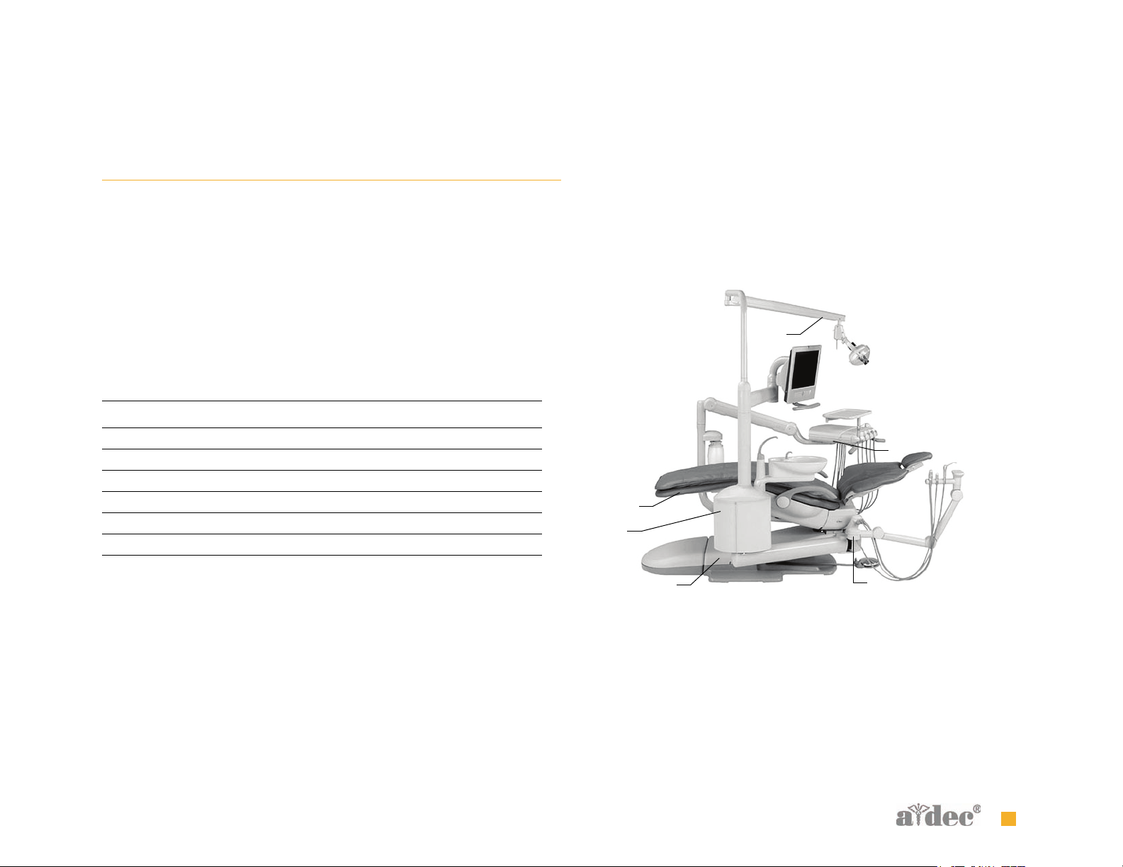
Item Description
1 Light, underside of the flexarm
2 Delivery system, underside of the delivery system
3 Chair, chair upper structure frame, under the toeboard
4 Cuspidor, inside support center
5 Assistant’s instrumentation, underside of the assistant’s arm
6 Power supply, inside motor pump area
Track light - on back of circuit breaker cover; wall-mounted - on top of
circuit breaker cover or at the very base of the post on the transformer
side; Preference-mounted - on the transformer cover underneath the
x-ray cap or at the end of the post by the transformer; ceiling-mounted on top of circuit breaker cover.
Figure 1 Serial/Model Number Locations on A-dec 500
1
3
4
6
5
2
85.0816.00 Rev B 2007-04 5
Page 17
A-dec Service Guide, Vol. II INTRODUCTION Reading Serial Number Labels
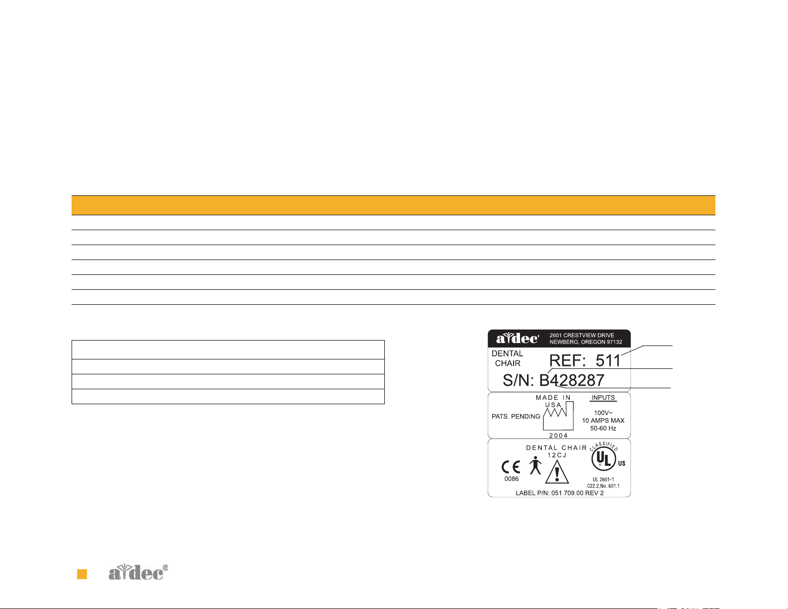
Reading Serial Number Labels
Use the tables shown and Figure 4 to reference how to identify serial/
model number information. The REF: number is the model number.
The S/N: is the serial number.
Tab l e 1 Month Identification Table
Letter Month Letter Month
A January G July
B February H August
C March I September
DApril J October
E May K November
F June L December
Item Description
1 Model number of the product
2 Month code (see Table 1)
3 Year the product was manufactured
The first letter of the serial number is the month the product was
manufactured (see Table 1). The first digit following the letter is the
year the product was manufactured.
Figure 2 Serial Number Label (511 chair)
1
2
3
6 85.0816.00 Rev B 2007-04
Page 18
A-dec Service Guide, Vol. II INTRODUCTION Recommended Tools
S ERVICE TOOLS
Recommended Tools
Table 2 lists the types of tools available from A-dec for servicing A-dec equipment and their recommended use:
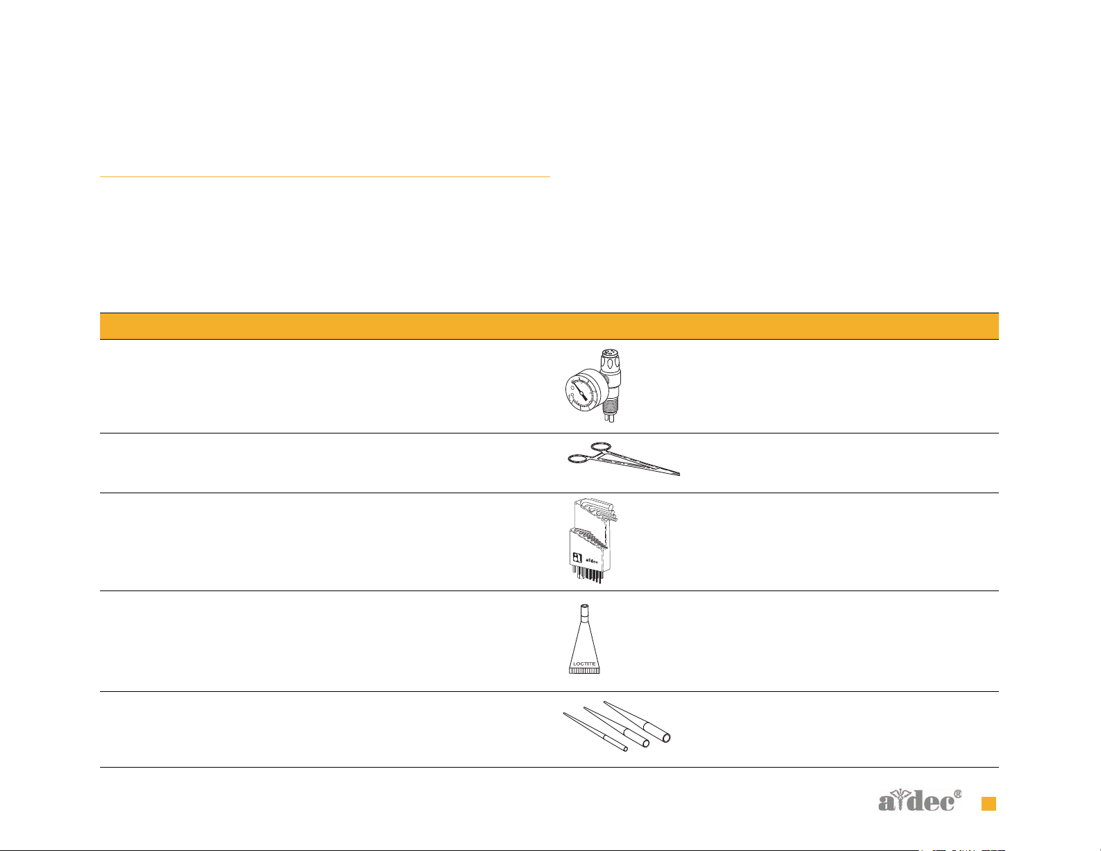
Tab l e 2 Recommended Tools
Tool Tas k Part Illustration Part Number
Drive air pressure gauge Adjusting handpiece drive air
pressure, 0-60 psi (4.13 bar). This
gauge does not fit the Borden 3-hole
coupler
50.0271.00
Hemostat Troubleshooting or repairing a unit to
stop air or water flow through tubing
Hex hey set Servicing or installing A-dec
equipment (plastic case included)
®
Loctite
O-ring tools Replacing O-rings during quick field
85.0816.00 Rev B 2007-04 7
Installing threaded fasteners to
prevent loosening
repairs (fits the four smallest O-ring
sizes)
009.008.00
009.018.00
060.001.00 (Red 271)
060.002.00 (Blue 242)
009.013.00
Page 19
A-dec Service Guide, Vol. II INTRODUCTION Recommended Tools
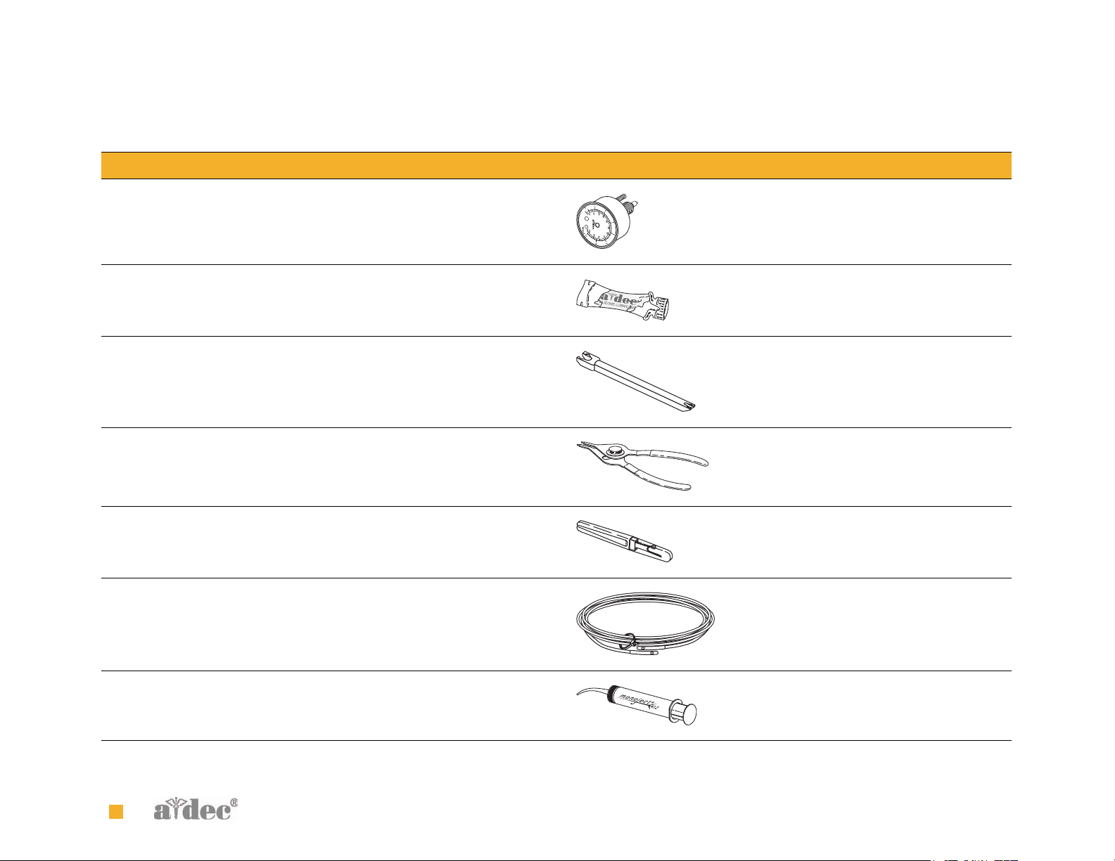
Tool Tas k Part Illustration Part Number
Panel mount gauge Checking air/water pressure
Can also be used as an inline pressure
gauge for testing purposes
026.118.00
Silicone lubricant Lubrication of internal moving parts
such as O-rings, oral evacuator valves,
and bushings
Sleeve tool Aid in securing 1/4" tubing sleeves
and 1/8" uni-clamps
Snap ring tool Installation and removal of internal
and external snap rings (fits all snap
rings used in A-dec equipment)
Tubing stripper Separation of the extruded air and
water lines in vinyl tubing
Umbilical stringer Route additional tubing or wiring
through existing umbilical assemblies
(12’ [3.66 mm] stringer with
threading holes on both ends)
Valve test syringe Quick tests of pilot operated valves;
used to apply a static pressure of 5-75
psi (.34-5.17 bar)
98.0090.01
98.0072.00
009.007.00
009.035.00
009.015.00
98.0050.01
8 85.0816.00 Rev B 2007-04
Page 20
A-dec Service Guide, Vol. II
DENTAL CHAIR
This section provides information related to servicing, maintenance,
and adjustments. Detail on how to service the chair and troubleshoot
specific problems is presented. For information on service parts, see the
Genuine A-dec Service Parts Catalog or contact A-dec customer service.
C HAIR CONTENTS
2
Product Overview, page 10
Flow Diagram, page 14
Service/Usage Information, page 16
Adjustments, page 27
Illustrated Parts Breakdown, page 29
85.0816.00 Rev B 2007-04 9
Page 21
P RODUCT OVERVIEW
Product Overview A-dec 511 Chair
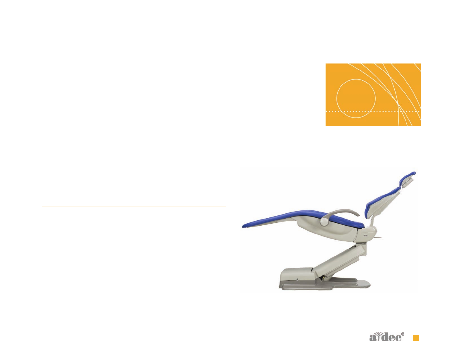
A-dec 511 Chair
The A-dec 511 chair provides a range of movements to position the
patient for dental treatment. The dental chair consists of a stable base,
an ergonomically synchronized seat and back support, adjustable head
support, and collapsible arm support. A footswitch and/or
touchpad(s) control the chair movement. A hydraulic system and four
programmable positions deliver entry, treatment, and exit positioning.
The deluxe touchpad option provides two operators with four more
programmable positions for a total of eight.
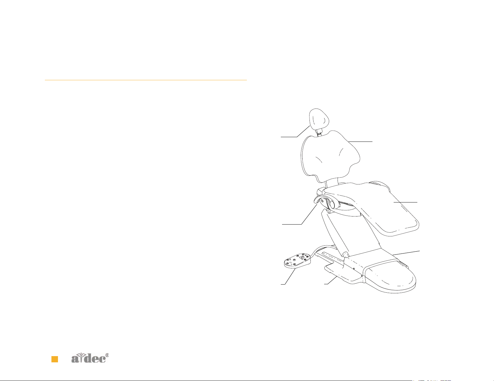
Figure 1 A-dec 511 Chair Features
A
B
E
F
G
C
(A) Headrest; (B) Armrest; (C) Foot Switch; (D) Baseplate; (E) Back; (F) Seat;
(G) Hydraulic Motor Pump Assembly
10 85.0816.00 Rev B 2007-04
D
Page 22
Product Overview A-dec 511 Chair Specifications
A-dec 511 Chair Specifications
Load Capacity
Patient Load: 300 lb. (135 kg) maximum
Accessory Load: 250 lb. (113 kg) maximum
Specifications are subject to change without notice.
NOTE Ensure the chair is bolted to the floor after installation.
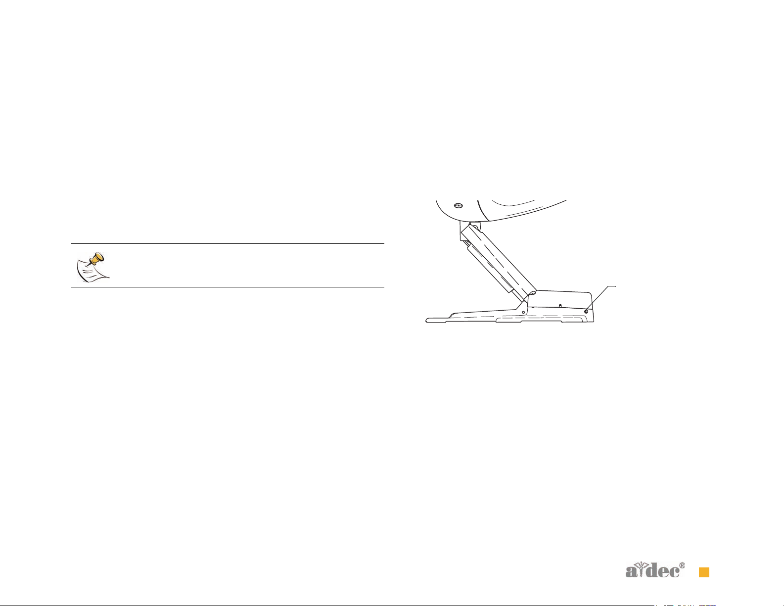
Power On/Off Button
The power On/Off button is located on the base of the chair, and is the
main disconnect that completely shuts down the electrical systems.
When the button is pressed in, power is on. When the button is out,
power is off.
Figure 2 On/Off Button
A
(A) On/Off Button
Limp-Along Feature
If there is a problem or malfunction, the limp-along feature allows the
operator to move the chair in the up direction for one second intervals
by pushing the manual control buttons on the touchpad or footswitch.
85.0816.00 Rev B 2007-04 11
Page 23
Product Overview A-dec 511 Chair Specifications
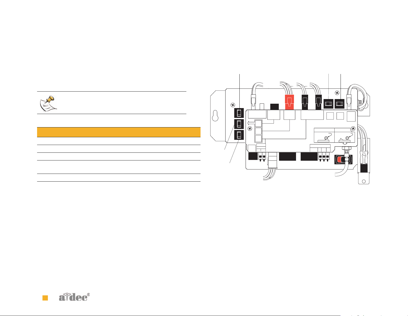
Chair Power Supply
The 300-watt power supply comes standard with the A-dec 511 chair. It
is located in the motor pump area of the chair. The total available
auxiliary load is a maximum of 4 Amps.
NOTE The electric switch connects the power supply to
pilot air.
Tab l e 3 Power Supply Circuit Breaker Function
Circuit Breaker Function
CB 1 Mains
CB 2 Mains
CB 3 Support side arm (side support arm)
CB 4 Assistant’s arm, control head (delivery system) and
chair circuit board.
CB 5 Dental light
Figure 3 Chair Power Supply Circuit Breaker Identification
CB 2
POWER ON MODE
NO CONNECTION
REQUIRED
SWITCH ON
13A @ 250V ~ MAX
VACUUM
NC NOCOM
RELAY
AMP
10
CB 4
CB 3
10
A
M
P
10
A
M
P
10
A
M
P
MAINS OUTPUT
POWER 4A MAX
CB 3
CB 4
CB 5
OUTPUT
8A MAX
DATA
OV~ 24V~
SIDE
SUPPORT
ARM
DENTAL
LIGHT
ASSITANT'S ARM
& CONTROL HEAD
CB 5
CB 1
AMP
10
CB 1CB 2
MASTER TOGGLE
CONTROL OF POWER
CONNECT AIR SUPPLY
FROM MASTER TOGGLE
SWITCH ON
MAINS
INPUT
12 85.0816.00 Rev B 2007-04
Page 24

Product Overview A-dec 511 Chair Specifications
85.0816.00 Rev B 2007-04 13
Page 25

Flow Diagram Chair Flow Diagram
F LOW DIAGRAM
Chair Flow Diagram
This flow diagram details both electrical and plumbing information for servicing and troubleshooting the A-dec 511 chair. The flow diagram is
located on the inside of the motor pump cover. This diagram includes the air electric switch, motor pump connections, and potentiometers.
14 85.0816.00 Rev B 2007-04
Page 26
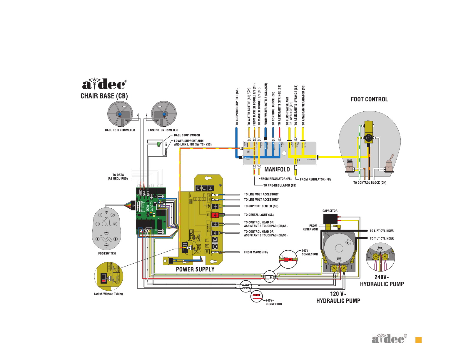
Figure 4 Chair Flow Diagram
Flow Diagram Chair Flow Diagram
85.0816.00 Rev B 2007-04 15
Page 27
S ERVICE/USAGE INFORMATION
Service/Usage Information Chair Covers
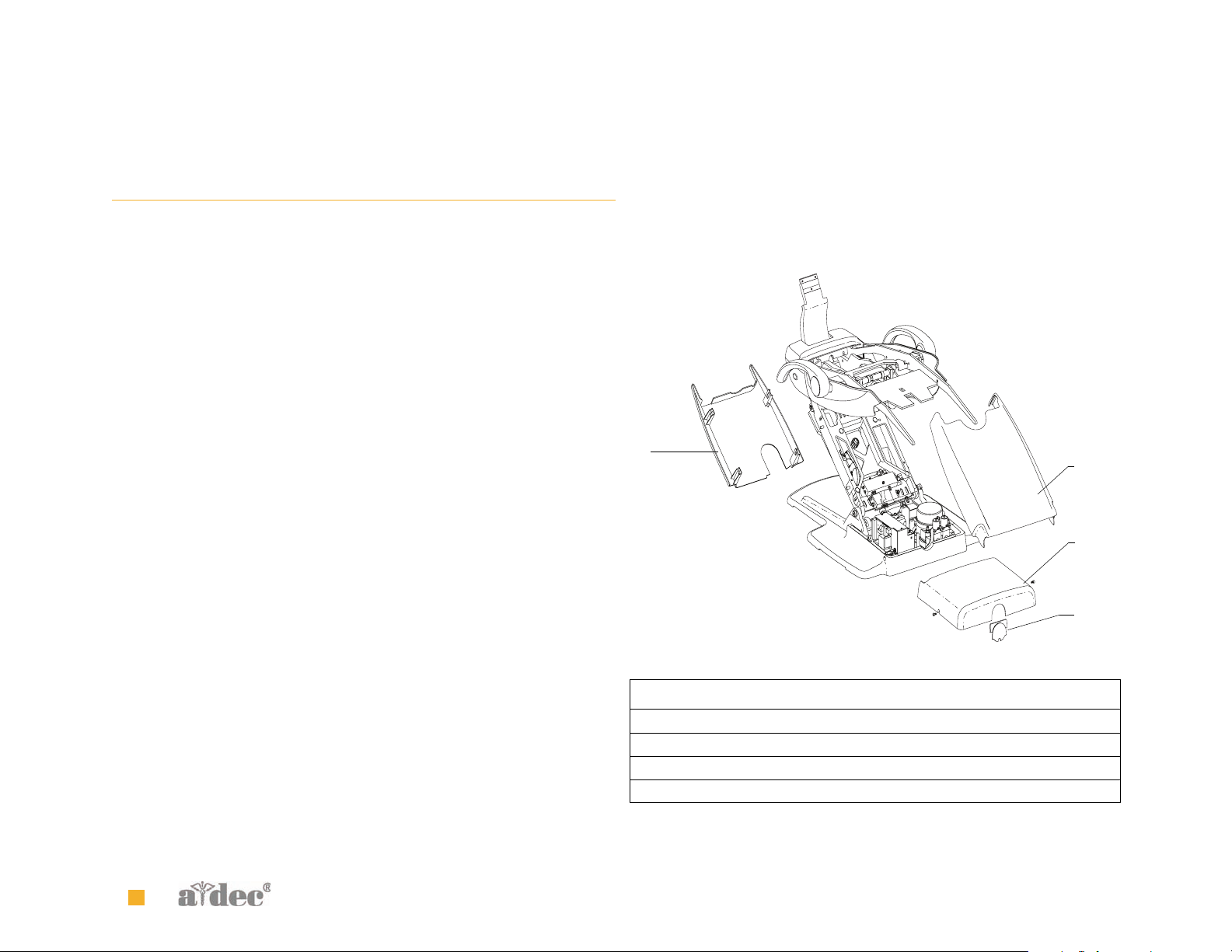
Chair Covers
The A-dec 511 chair motor pump, lift arm and stop plate covers are
removed in the following order:
1. Motor Pump Cover
• To remove: Remove screw from each side and lift up.
• To replace: Replace cover, and attach with two screws.
2. Lift Arm Cover
• To remove: Pull one side of the cover until it releases from the
lift arm.
• To replace: Align one side of the cover with the lift arm and snap
into place. Ensure both sides are firmly attached.
3. Stop Plate
• To remove: Pull one side of the cover until it releases from the
lift arm.
• To replace: Slide one side of the cover over the post on the lift arm
and attach.
Figure 5 A-dec 511 Chair Covers
3
Item Part Number Description
1 62.0080.00 Motor pump cover
2 62.0081.00 Lift arm cover
3 62.0084.00 Stop plate cover
4 62.0101.00 Motor pump cover plug
2
1
4
16 85.0816.00 Rev B 2007-04
Page 28

Service/Usage Information Factory Default Routine
Factory Default Routine
When a new circuit board is installed in the chair, the circuit board
needs to run the factory default routine to learn the range of motion of
the chair.
The routine:
• sets the base and back upper limits
• calculates new presets based on actual range of motion of the chair
• verifies that the potentiometers work
To start the factory default routine, place the “spare” jumper in the
factory default position on the P3 test points of the chair circuit board.
When running the factory default routine the chair:
1. Moves base down
2. Moves base up
3. Moves back down
4. Moves back up
5. Moves base and back to Position 0
6. Beeps three times
NOTE The jumper must remain in the factory default position
to complete the factory default routine. The status LEDs on the
standard and deluxe touchpads and the chair circuit board
double blink while the factory default routine is running and
after the routine is complete.
85.0816.00 Rev B 2007-04 17
Page 29

Chair Circuit Board Components
Service/Usage Information Chair Circuit Board Components
Part No: 90.1072.00
Item Description
1 P7, P8, P9 - Data line ports
2 DS4 - Stop switch LED (limit switch) and P10 connector
3 DS5 - Back potentiometer LED and P1 connector
4DS6 - Base potentiometer LED and P2 connector
5 P5 - Footswitch connector
6P3 - Test points
7 DS12 - Base down LED and relay K5
8 DS11 - Base up LED and relay K4
9DS10 - Back down LED and relay K3
10 DS9 - Back up LED and relay K2
11 DS1 - AC power LED
12 DS2 - Status LED
13 DS3 - Data LED
14 DS13 - Chair lockout LED and terminal strip J1
15 J2 - Ø VAC terminal strip (output)
16 J2 - 24VAC terminal strip (output)
17 P4 - Input power and dental light connector
18 J3 - Vacuum relay K7 and output terminal strip
19 P11 - Pump motor and solenoid connector
20 DS8 - Dental light LED and relay K1
21 DS7 - Dental light LED and relay K6
18 85.0816.00 Rev B 2007-04
Page 30
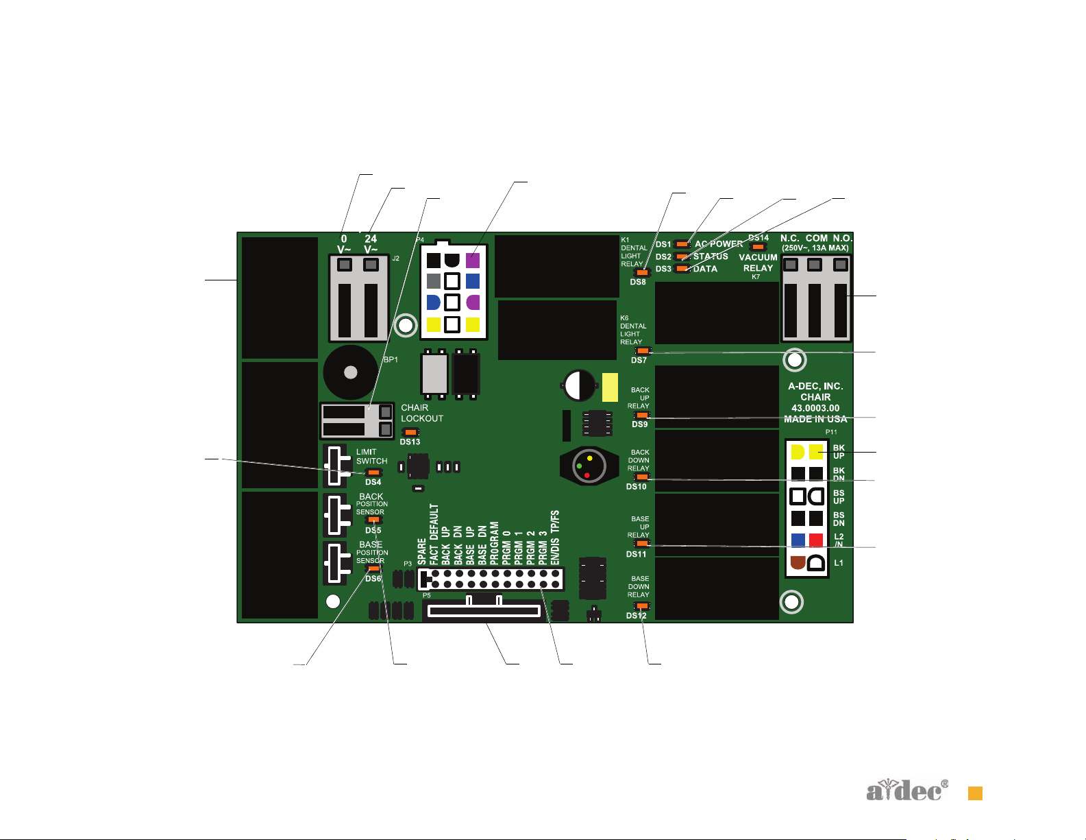
Figure 6 A-dec 511 Chair Circuit Board Components
15
1
16
14
17
Service/Usage Information Chair Circuit Board Components
20
11
12
13
18
21
10
2
19
9
8
4
85.0816.00 Rev B 2007-04 19
3 5 6 7
Page 31

LED Identification
Figure 4 describes the LEDs on the chair circuit board.
Tab l e 4 LED Identification
LED Status Description
Service/Usage Information Chair Circuit Board Components
DS1 - AC power
LED
DS2 - Status LED Off System is not functioning, no power or circuit board has failed
DS3 - Data LED Off No DCS communication, not connected to the DCS, or DCS has failed
DS4 - Chair limit
switch
DS13 - Chair
lockout
DS5 + DS6 - Chair
potentiometers
DS9, DS10, DS11,
DS12 - Chair relay
LEDs
DS7, DS8 - Dental
light relay LEDs
DS14 - Vacuum
relay LED
Off No 24 VAC power, tripped circuit breaker, power supply turned off, no line voltage
Green, steady 24VAC at the terminal strip
Green, steady Normal operation
Green, steady Detects active DCS
Green, blinking Valid DCS Message
Off Closed, (normal)
Red Open, (activated)
Off Open, (normal)
Red Closed, (activated)
Off Potentiometer:
• Not connected or bad connection
• Moving in wrong direction
• Limited range of motion, or
• Cable is not on wheel
Yellow, steady Normal operation
Yellow, fast blink Upper end of travel
Off Relay is off
On Relay is on
Off Relay is off
On Relay is on
Off Relay is off
On Relay is on
20 85.0816.00 Rev B 2007-04
Page 32

Service/Usage Information The Hydraulic System
The Hydraulic System
The hydraulic system deactivates automatically at the upper and lower
extremes of travel. The system is leak-free during transportation,
storage, and operation. The hydraulic system consists of:
• Hydraulic fluid reservoir
•Hydraulic cylinders
• Motor-driven hydraulic pump with solenoids
Hydraulic Fluid Reservoir
The hydraulic fluid reservoir is located in the lift arm of the chair under
the stop plate cover. You can see the fluid level in the reservoir through
the sides of the reservoir. A top fill cap allows you to add fluid. The
hydraulic system holds 40 ounces (2.5 pints [1.18 l]) of hydraulic fluid.
To fill the reservoir:
1. Place the chair in the full base and back up position.
2. Fill to the green Max line (see Figure 7).
CAUTION Do not over fill.
Figure 7 Hydraulic Fluid Reservoir
A
B
3. Cycle the chair after the reservoir is filled.
(A) Max Level; (B) Min Level
85.0816.00 Rev B 2007-04 21
Page 33

Service/Usage Information The Hydraulic System
Hydraulic Cylinders
The hydraulic cylinders operate during the Base Up and Back Up
functions. Springs and gravity retract the piston during Base Down
and Back Down functions.
The chair seat travels vertically from a low point of 13.5" (343 mm) to a
high point of 31.5" (800 mm) above the floor (see Figure 8).
Motor-driven Hydraulic Pump
The hydraulic pump takes hydraulic fluid from the reservoir and
pressurizes it to extend the chair lift and tilt hydraulic cylinders for
back and base up functions. The bi-directional pump rotates one
direction for Base Up and the opposite direction for Back Up. The
solenoids mounted to the pump assembly gate hydraulic fluid from the
two cylinders. Depending on the chair Down function, the controller
selects which solenoid-actuated manifold valves are open or closed.
The 100-120 VAC pump and 220-240 VAC pump are equipped with an
automatic reset 110°C (230°F) thermal limiter. There are no serviceable
parts on the hydraulic pump other than the solenoids.
NOTE You can not adjust the speed of the chair.
Figure 8 Hydraulic Cylinder Operation
13.5"
343mm
31.5"
800mm
22 85.0816.00 Rev B 2007-04
Page 34

Capacitor
Part No: 041.642.00, 100 VAC
Part No: 041.643.00, 110 - 120 VAC
Part No: 041.644.00, 220 - 240 VAC
The capacitor is energized during chair Base Up or Back Up functions.
Figure 9 A-dec 511 Chair Capacitor
Service/Usage Information The Hydraulic System
A
(A) Capacitor
85.0816.00 Rev B 2007-04 23
Page 35

Service/Usage Information The Hydraulic System
Solenoids
Part No: 90.1070.00, 110 - 120 VAC
Part No: 90.1071.00, 220 - 240 VAC
How to Test Solenoids
A solenoid is entergized during Base Down and Back Down functions.
To check for a failed solenoid, test the solenoids using a volt/ohm
meter or magnetic pull test:
Magnetic pull
1. Hold a paper clip loosely in your hand.
2. Activate the solenoid by pressing Base Down or Back Down on the
footswitch or touchpad.
3. If there is a pull on the paper clip, the solenoid is being entergized.
Coil resistance
1. Disconnect the solenoid power at the 2-position connector.
2. Place on Ohm meter probe on each of the solenoid connector
terminals.
100 - 120 VAC = 177 Ohms ± 18 Ohms
220 - 240 VAC = 845 Ohms ± 85 Ohms
WARNING You must depressurize the base or back system
prior to removing the solenoid.
1. Depressurize base or back system,
2. Remove the failed solenoid coil
3. Replace with the operating solenoid coil.
4. Lower the chair base and back.
Figure 10 A-dec 511 Chair Solenoids
B
C
A
NOTE If the solenoid is hot, then the resistance reads higher.
NOTE When replacing a solenoid, wipe up any oil, and
replace existing O-rings on the solenoid base.
ELECTRICAL WARNING The solenoid coils are powered by line
voltage (100, 120, or 240 VAC). Failure to unplug the chair may
result in serious injury from electrical shock.
(A) Base Down Solenoid; (B) Back Down Solenoid; (C) Motor Pump Assembly
24 85.0816.00 Rev B 2007-04
Page 36

Service/Usage Information Potentiometer
v
U
R
U
R
AZ762 - 1C-5D
C
VDE
Potentiometer
The potentiometer and cable assembly is a simple, accurate unit, which eliminates position float. “Float” is a slight change or variation in the
pre-programmed positions. The chair uses the same potentiometer assembly for both lift and tilt requirements. If a potentiometer should fail, the
limp-along feature allows the operator to position the chair for one second intervals by pushing the manual control buttons on the
touchpad or footswitch.
Figure 11 Location of the Chair Base Up and Back Up Potentiometers
A
B
D
v
AZ762 - 1C-5
U
R
U
R
E
C
VD
(A) Base Up Potentiometer; (B) Back Up Potentiometer
85.0816.00 Rev B 2007-04 25
Page 37

Service/Usage Information Chair Stop Plate
Chair Stop Plate
The chair stop switch stops chair movement when you press the stop
plate. Should anything inadvertently become lodged under the chair,
press Base Up on the touchpad or footswitch to raise the chair so you
can remove the object. As long as you apply pressure to the stop plate,
the chair does not move down.
The stop plate has only one switch. The switch and all other parts snap
into place for easy removal or replacement. No tools are required.
WARNING Be sure to power off the chair and disconnect
it from its power source before replacing the stop switch.
CAUTION Cable tie the wires to the lift arm to prevent
kinking and pinching.
Chair Bump-Up Feature
The chair stop plate and the assistant’s arm trigger the chair to move
upwards if it was moving down when the stop plate switch
was activated.
Figure 12 A-dec 511 Chair Stop Plate
A
(A) Stop Switch Assembly
26 85.0816.00 Rev B 2007-04
Page 38

A DJUSTMENTS
Adjustments Swivel Brake
Swivel Brake
The chair can rotate to any position within 30° either side of center. The
chair swivel brake keeps the chair from moving. To engage the brake,
push the brake lever firmly to the left. To release the swivel brake, push
the brake lever to the right.
Tension Adjustment
If the chair swivels left or right with the brake engaged or if it is
difficult to move with the brake disengaged, adjust the swivel brake
tension. To adjust the tension, use a 5/32 hex key and turn the tension
adjustment screw;
• Clockwise to increase brake friction
• Counterclockwise to decrease brake friction.
If you cannot obtain proper adjustment through rotation of the hex
key, replace the brass brake pad by removing the brake handle and
using a hex key to disengage the pad. Remove the old pad and replace
with new one. Replace the brake handle and handle retainer.
NOTE To disable the swivel feature, reinstall the shipping pin.
Figure 13 Chair Swivel
30°
30°
Figure 14 Swivel BrakeTension Adjustment
A
Engaged
(A) Tension Adjustment Screw
85.0816.00 Rev B 2007-04 27
Released
Page 39

Adjustments Headrest
Headrest
The headrest adjustment lever allows you to use one hand to adjust the
headrest. When the lever is released, the headrest holds its position.
Drift Adjustment
If the headrest drifts downward, or if it is difficult to move up or down,
adjust the glide bar tension. To adjust the tension, use a 1/8 hex key
and turn the tension adjustment screw clockwise to increase friction or
counterclockwise to decrease friction.
Figure 15 Headrest Adjustments
C
A
B
(A) Headrest Adjustment Lever; (B) Glide Bar;
(C) Glide Bar Tension Adjustment
28 85.0816.00 Rev B 2007-04
Page 40

I LLUSTRATED PARTS BREAKDOWN
Illustrated Parts Breakdown Part Identification
This section contains illustrated parts breakdowns specific to the
A-dec 511 Chair.
Part Identification
The conventions for the serviceable components tables are designed to
identify all parts and kits, including ones that are not for sale. Symbols
with reference notes are used.
Symbol Definition
†
No symbol Part is for sale
Indicates that the individual part is not available for
sale (these parts are typically part of a kit and/or
larger assembly that is for sale)
C HAIR IPB CONTENTS
Baseplate and Motor Pump Assembly, page 30
Hydraulic Hose and Solenoid Assembly, page 32
Lift Cylinder and Link Arm, page 34
Lower Assembly, page 36
Upper Structure/Swivel Assembly, page 38
Back and Tilt Cylinder Assembly, page 40
Upper (Springs and Cam Assembly ), page 42
Upper (Seat Assembly), page 44
Headrest Assembly, page 46
85.0816.00 Rev B 2007-04 29
Page 41

Illustrated Parts Breakdown Baseplate and Motor Pump Assembly
Baseplate and Motor Pump Assembly
Item Part Number Description
1 002.010.00 Screw, socket head, patch, 1/4-20 x 3/8" stainless steel
2 90.1073.00 Power supply, 100V
90.1074.00 Power supply, 120V
90.1075.00 Power supply, 240V
3 90.1082.00 Stand-off, package of 5
4 90.1072.00 Chair PCB (includes item #3 stand-offs)
5 62.0029.00† Baseplate
6 005.008.01 Screw, 1/4-20 x 1/2"
7 001.229.00 Screw, truss head, Phillips, 6-32 x 1/2", stainless steel
8 041.642.00 Capacitor, 100V
041.643.00 Capacitor, 110-120V
041.644.00 Capacitor, 220-240V
9 006.141.00 Nut, hex, KEPs 1/4-20
10 037.040.00 Isolator
11 90.1094.00 Hydraulic motor pump assembly, 100V
90.1094.01 Hydraulic motor pump assembly, 120V
90.1094.02 Hydraulic motor pump assembly, 240V
12 025.112.00 Clamp, half type
13 002.120.00 Screw, socket head, patch, 1/4-20 x 1" stainless steel
14 62.0131.00 Strain relief
15 Spring - Part of Main On/Off Switch Kit, P/N 90.1068.00
16 Button - Part of Main On/Off Switch Kit, P/N 90.1068.00
30 85.0816.00 Rev B 2007-04
Page 42

Figure 16 Baseplate and Motor Pump Assembly
Illustrated Parts Breakdown Baseplate and Motor Pump Assembly
1
2
3
4
5
13
14
1
12
6
7
8
9
10
11
15
16
85.0816.00 Rev B 2007-04 31
Page 43

Illustrated Parts Breakdown Hydraulic Hose and Solenoid Assembly
Hydraulic Hose and Solenoid Assembly
Item Part Number Description
1 62.0046.00 Hydraulic hose, lift
2 001.250.00 Screw, socket head cap, 8-32 x 5/8", black
3 90.1070.00 Solenoid, 110-120V, kit
90.1071.00 Solenoid, 220-240V, kit
4
5 62.0047.00 Hydraulic hose, tilt
035.055.00
†
O-ring, 5.8mm ID x 1.9 W, Buna
32 85.0816.00 Rev B 2007-04
Page 44
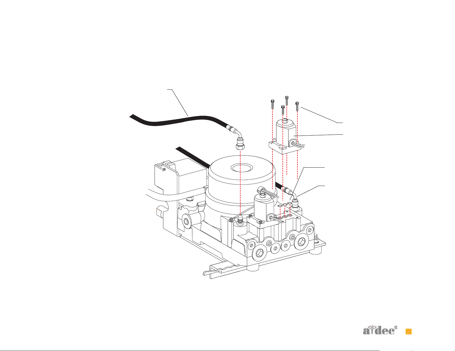
Figure 17 Solenoid Assembly
Illustrated Parts Breakdown Hydraulic Hose and Solenoid Assembly
1
2
3
4
5
85.0816.00 Rev B 2007-04 33
Page 45

Illustrated Parts Breakdown Lift Cylinder and Link Arm
Lift Cylinder and Link Arm
Item Part Number Description
1 90.1083.00 Lift cylinder assembly
2 002.120.00 Screw, socket head patch, 1/4-20 x 1" stainless steel
3 62.0135.00 Pin
4 010.031.01 Retaining e-ring, external 1/2" ID, stainless steel
5 62.0078.01 Link arm
6 62.0134.00 Pin, link arm
7 90.1095.00 Kit, Stop switch replacement
34 85.0816.00 Rev B 2007-04
Page 46

Figure 18 Lift Cylinder and Link Arm
Illustrated Parts Breakdown Lift Cylinder and Link Arm
1
2
3
4
5
6
7
85.0816.00 Rev B 2007-04 35
Page 47

Illustrated Parts Breakdown Lower Assembly
Lower Assembly
Item Part Number Description
1
2
3
4 004.148.00 Washer, flat nylatron
5 001.165.00 Screw, socket shoulder, 1/2-13 x 5/8 x 7/8
6 010.031.01 Retaining e-ring, external 1/2" ID stainless steel
7 62.0077.00 Pin, linkarm
8 002.010.00 Screw, socket head patch, 1/4-20 x 3/8" stainless steel
9 90.1069.00 Potentiometer
10 005.008.01 Screw, 1/4-20 x 1/2"
11 38.1804.00 Manifold assembly
62.0091.00
62.0089.00
011.124.00
90.1083.00 Kit, Lift cylinder (includes 1, 2 and 3)
†
†
†
Swivel mount
Liftarm
Pin, clevis
36 85.0816.00 Rev B 2007-04
Page 48

Figure 19 Lower Assembly
Illustrated Parts Breakdown Lower Assembly
4
5
1
2
3
6
7
8
9
10
11
85.0816.00 Rev B 2007-04 37
Page 49

Illustrated Parts Breakdown Upper Structure/Swivel Assembly
Upper Structure/Swivel Assembly
Item Part Number Description
1
2 62.0237.00 Wear ring, 2-3/4 OD x 5/8"
3 016.133.00 Thrust bearing
4 61.2051.00 Locknut, spanner
5 62.0218.00 Brake handle assembly
6 005.008.01 Screw, 1/4-20 x 1/2" socket head
7 004.170.00 Washer, flat, nylon
8 62.0042.00 Adjuster, brake
9 62.0043.00 Plunger, brake
10 011.097.00 Ship pin
62.0050.00
†
Upper structure
38 85.0816.00 Rev B 2007-04
Page 50

Figure 20 Upper Structure/Swivel Assembly
Illustrated Parts Breakdown Upper Structure/Swivel Assembly
4
3
5
6
7
1
2
3
8
9
10
85.0816.00 Rev B 2007-04 39
Page 51

Illustrated Parts Breakdown Back and Tilt Cylinder Assembly
Back and Tilt Cylinder Assembly
Item Part Number Description
1 010.031.01 Retaining e-ring, 1/2" ID stainless steel
2 62.0201.00 Bolt, spring support
3 62.0202.00 Bolt, slider, shoulder
4 016.145.00 Bearing, flanged, .75 ID x .8125 OD
5 62.0200.00 Tvunnion
6 90.1085.00 Tilt cylinder assembly
7 62.0199.00 Trolley, chair back
8 002.010.00 Screw, socket head patch, 1/4-20 x 3/8" stainless steel
9 90.1069.00 Potentiometer
10 62.0061.00 Back track slider
11 62.0189.00 Spacer
12 005.036.00 Screw, 3/8-16 x 1-3/4, 2N, patch
13 005.138.01 Screw, button head socket, 10-32 x 5/16 patch
14 99.0719.00 Bracket
15 001.244.00 Screw, JCB, socket, 1/4-20 x 15mm, stainless steel
16 001.245.00 Screw, socket head, cap, 1/4-20 x 3/4"
17 62.0103.00 Wear pad, upper headrest brake
18 62.0102.00 Wear pad, lower headrest brake
19 006.148.00 Coupling
20 007.158.00 Setscrew, cone point, 1/4-20 x 1" stainless steel
21 90.1099.00 Support, back
40 85.0816.00 Rev B 2007-04
Page 52

Figure 21 Back and Tilt Cylinder Assembly
7
Illustrated Parts Breakdown Back and Tilt Cylinder Assembly
1
2
3
4
5
6
11
12
8
9
10
15
16
13
14
17
18
19
20
21
85.0816.00 Rev B 2007-04 41
Page 53

Illustrated Parts Breakdown Upper (Springs and Cam Assembly )
Upper (Springs and Cam Assembly )
Item Part Number Description
1 62.0070.00 Guide, lateral
2 001.245.00 Screw, socket head, cap, 1/4-20 x 3/4"
3 62.0067.00 Roller, cam
4 013.114.00 Spring
5 010.031.01 Retaining e-ring, external 1/2" ID, stainless steel
6 62.0185.00 Spring, support
7 77.0206.00 Cam
8 001.163.00 Screw, hex head
42 85.0816.00 Rev B 2007-04
Page 54

Figure 22 Upper (Springs and Cam Assembly)
1
2
3
4
5
6
Illustrated Parts Breakdown Upper (Springs and Cam Assembly )
7
8
85.0816.00 Rev B 2007-04 43
Page 55

Illustrated Parts Breakdown Upper (Seat Assembly)
Upper (Seat Assembly)
Item Part Number Description
1 016.065.00 Bearing, flanged, .500 ID x .562 OD
2 90.1103.00 Seat frame (includes items 1 and 3)
3 62.0196.00 Stud, mounting, shoulder, 7/16-4
4 62.0067.00 Roller, cam
5 62.0062.00 Cam seat lift
6 010.031.01 Retaining e-ring, external, 1/2" ID, stainless steel
7 62.0185.00 Spring support
8 62.0069.00 Bar
44 85.0816.00 Rev B 2007-04
Page 56
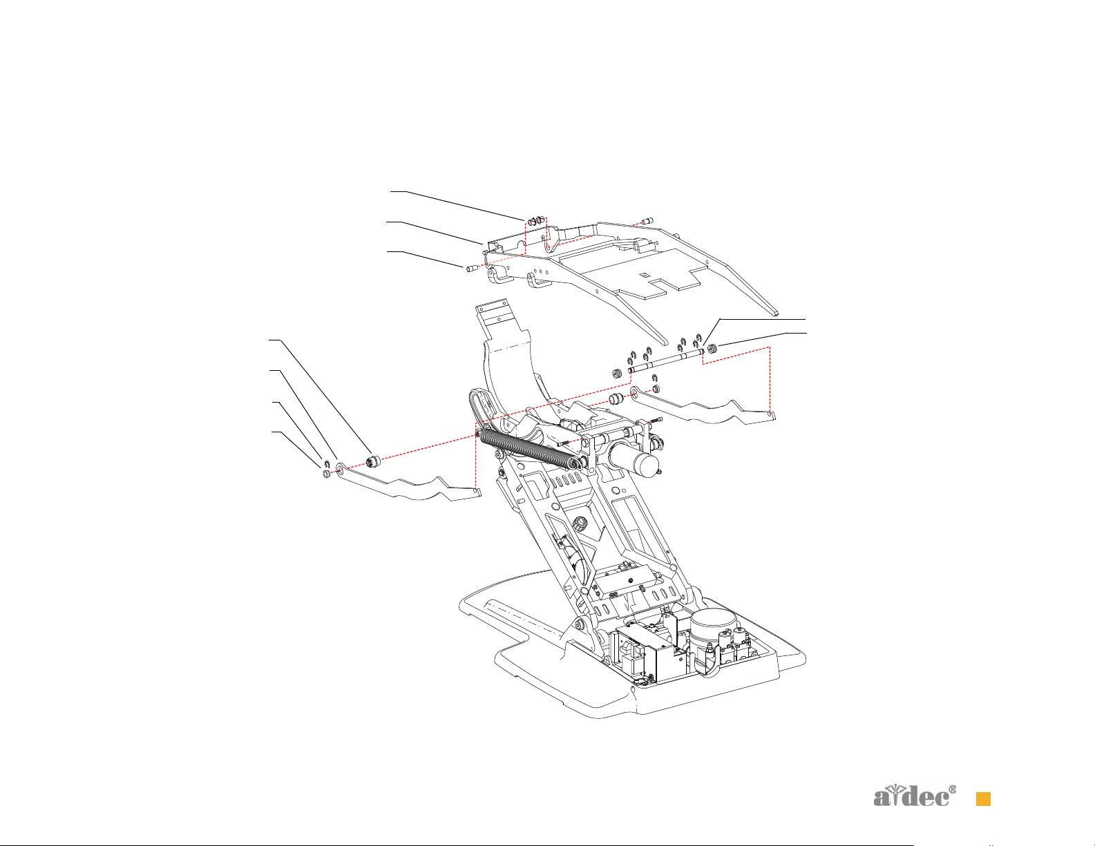
Figure 23 Upper (Seat Assembly)
4
5
6
7
Illustrated Parts Breakdown Upper (Seat Assembly)
1
2
3
8
7
85.0816.00 Rev B 2007-04 45
Page 57

Illustrated Parts Breakdown Headrest Assembly
Headrest Assembly
Item Part Number Description
1 035.048.01 O-ring, E, .115 ID x .07 W, package of 10
2 90.1092.00 Cover, headrest cushion
3 001.042.01 Screw, socket head, 6-32 x 1/2", stainless steel, patch
4 62.0021.00 Bearing, slider, headrest cushion
5 90.1091.00 Headrest assembly (includes items 3, 4, 6, 7 and 8)
6 62.0094.00 Bearing, slider, brake, headrest
7 013.005.00 Spring
8 62.0141.00 Cap, headrest
9 001.021.00 Screw, socket head, 4-40 x 1/2", stainless steel
46 85.0816.00 Rev B 2007-04
Page 58

Figure 24 Headrest Assembly
Illustrated Parts Breakdown Headrest Assembly
6
7
1
2
3
4
5
8
9
85.0816.00 Rev B 2007-04 47
Page 59

Illustrated Parts Breakdown Headrest Assembly
48 85.0816.00 Rev B 2007-04
Page 60

A-dec Service Guide, Vol. II
3
PROGRAMMING
The A-dec 500 touchpad centralizes treatment room controls into one
touch surface. Some touchpad buttons have indicators to alert you if
the operation is functioning. A-dec touchpads control multiple chair
and delivery system functions:
• Standard Touchpad—chair, light, cuspidor controls and auxiliary
equipment
• Deluxe Touchpad—chair, light, cuspidor, air/water coolant, electric
handpiece, scaler, multiple users and auxiliary equipment
This section provides programming information for all of the A-dec
500 modules as well as information related to servicing, maintenance,
and adjustments. For information on service parts, see the Genuine
A-dec Service Parts Catalog or contact A-dec customer service.
P ROGRAMMING CONTENTS
Status Icon, page 50
Chair Positions, page 51
Cuspidor Functions, page 54
Dental Light, page 55
Electric Handpiece Settings (Deluxe Touchpad Only), page 56
Other System Choices, page 60
Touchpad Circuit Board Components, page 62
85.0816.00 Rev B 2007-04 49
Page 61

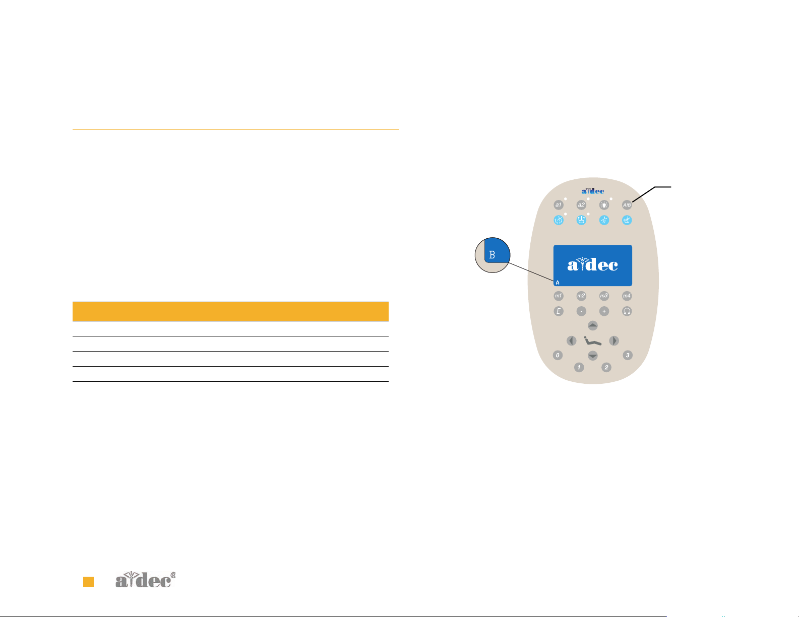
A-dec Service Guide, Vol. II Status Icon
S TATUS ICON
The A-dec logo on the Deluxe touchpad indicates the system status:
• Solid blue—normal operation and power is on.
• Blinking— chair stop plate or cuspidor limit switch is active.
The icon returns to solid blue once you remove any obstructions.
• Double blink pattern—jumper is on the factory default position on
the chair circuit board. The icon returns to solid blue once you
remove the jumper.
Figure 25 Deluxe Touchpad
A
(A) Status Icon
50 85.0816.00 Rev B 2007-04
Page 62

A-dec Service Guide, Vol. II Chair Posi tions
C HAIR POSITIONS
The chair direction arrows on the touchpad allow you to manually move the chair base up/down and back up/down. Table 5 lists and describes
the direction arrows:
Tab l e 5 Chair Direction
Icon Action
Back down
Base down
Back up
Base up
85.0816.00 Rev B 2007-04 51
Page 63

A-dec Service Guide, Vol. II Chair Positions Position Buttons
Position Buttons
Chair position buttons are factory preset to automatically move the
chair (see Figure 26).
Figure 26 Chair Position Touchpad Buttons
C
A
A
B
B
Table 6 lists and describes the factory presets:
Tab l e 6 Chair Position Factory Presets
Button Description
Entry/exit Position. Automatically positions chair and
turns off dental light.
Position 1. Automatically positions the chair base and
back and turns on the dental light.
Position 2. Automatically positions the chair base and
back and turns on the dental light.
Position 3 (x-ray/rinse). Automatically positions the
chair back to either x-ray or the previous position.
Toggles between the two positions and turns on/off the
dental light as appropriate.
(A) Chair Direction Arrow; (B) Chair Position Button; (C) Program Button
52 85.0816.00 Rev B 2007-04
Page 64

A-dec Service Guide, Vol. II Chair Positions Position Buttons
Customize Chair Positions 0-2
To customize the chair positions:
1. Use the manual controls to adjust the chair position as desired.
2. Press and release the Program button. One beep indicates
programming mode.
3. Press the chair position button, within four seconds, you wish to
reset (for example, Position 1). Three beeps indicate the new setting
is programmed in memory.
Customize Chair Position 3
Position 3 functions either as a toggle between x-ray/rinse position and
last position or as a programmable position. To customize:
1. Press and hold the program button and the Position 3 button
simultaneously for three seconds. Three beeps confirm the
x-ray/rinse position is now inactive, and the chair is available for
programming.
2. Press the manual chair controls (arrow icons) to position the chair
to the desired operating position.
3. Press and release the program button. One beep confirms
programming mode.
4. Within 3 seconds, press the Position 3 button. Three beeps indicate
the new setting is programmed in memory.
NOTE If Position 3 is changed to a programmable
position, it operates the same as Positions 1 and 2.
To reactivate the x-ray/rinse function:
Press and hold the program button and the Position 3 button
simultaneously for three seconds. Three beeps confirm the x-ray/rinse
position is now active.
85.0816.00 Rev B 2007-04 53
Page 65

A-dec Service Guide, Vol. II Cuspidor Functions Cup Fill
C USPIDOR FUNCTIONS
Cup Fill
The cup fill function controls water flow from the cuspidor into a cup
(see Figure 27).
Figure 27 Cup Fill Button
• Press the cup fill button for a timed operation. The factory preset is a
2.5 second fill.
• Press and hold the cup fill button for manual operation.
Bowl Rinse
Bowl rinse provides rinse water for the cuspidor bowl (see Figure 28).
Figure 28 Bowl Rinse Button
• Press the bowl rinse button for a timed operation. The factory preset
is a 30 second rinse.
• Press and hold the bowl rinse button for manual operation.
Customize Cup Fill and Bowl Rinse
To program the cup fill and bowl rinse timing:
1. Press and release the Program button. One beep indicates
programming mode.
2. Within 3 seconds, press and hold the cup fill or bowl rinse button
for the desired time.
3. Release the button. Three beeps confirm the setting.
NOTE If you have a Standard touchpad and wish to use
the Auxiliary (A1/A2) buttons, automated cup fill and
bowl rinse features are not available.
NOTE If you press the bowl rinse button twice in less
than two seconds, it switches to continuous operation
mode. Press the button once to end the continuous bowl
rinse mode.
54 85.0816.00 Rev B 2007-04
Page 66

A-dec Service Guide, Vol. II Dental Light Dental Light Auto Feature
D ENTAL LIGHT
The dental light button on the touchpad functions as a three-way
switch. You can turn the dental light on or off from either the touchpad
or the dental light (see Figure 29).
Figure 29 Dental Light Button
Press the dental light button to turn on the dental light. Press the
button again to toggle between two intensity settings. The dental light
toggles between composite-medium intensity or composite-high
intensity settings. When the dental light is in composite mode, the
indicator light next to the button blinks (see Figure 30). Hold the button
1 second to turn the dental light off.
Figure 30 Dental Light Composite Mode
A
Dental Light Auto Feature
The dental light has an auto on/off feature. When you use a
programmed chair position (1 or 2), the dental light turns on when the
chair reaches operating position. Press Position 0 (entry/exit) or
Position 3 (x-ray/rinse) and the dental light automatically turns off.
NOTE If Position 3 has been changed to a
programmable position, it operates the same as Positions
1 and 2.
To activate/deactivate:
• Press and hold the program and light button simultaneously for
three seconds. One beep confirms the factory preset is off.
• Press and hold the program and light button simultaneously for
three seconds. Three beeps confirming the factory preset is on.
(A) Dental Light Composite Mode Blinking Indicator
85.0816.00 Rev B 2007-04 55
Page 67
A-dec Service Guide, Vol. II Electric Handpiece Settings (Deluxe Touchpad Only) Standard Mode
E LECTRIC HANDPIECE SETTINGS (DELUXE TOUCHPAD ONLY)
Standard Mode
Activate the electric motor by withdrawing the handpiece from the
holder. The settings that appear are the ones last used for that
handpiece position.
The electric handpiece allows you to choose a precise pre-set speed or
to “feather” up to that speed. Figure 7 lists the factory presets for
electric handpieces:
Tab l e 7 Electric Motor, Air and Water Coolant Presets (Standard Mode)
Memory Button Preset Speed Air Coolant Water Coolant
M1 2,000 RPM On On
M2 10,000 RPM On On
M3 20,000 RPM On On
M4 40,000 RPM On On
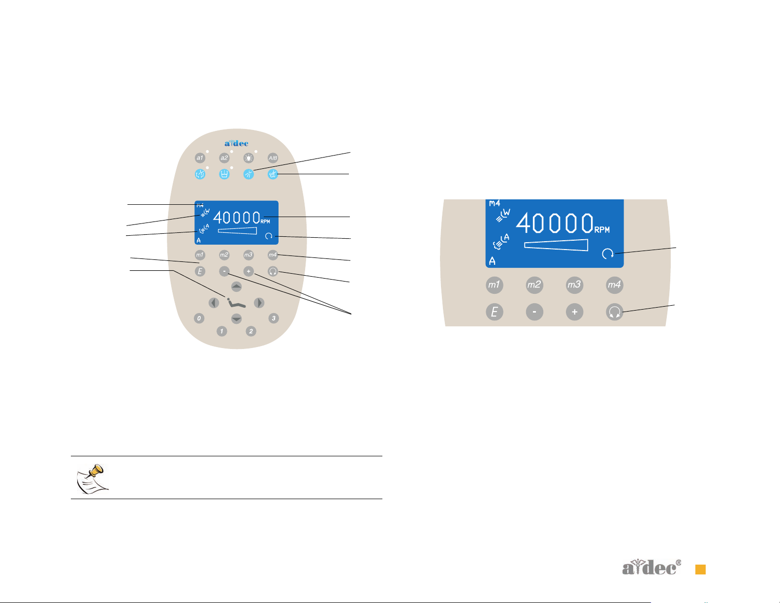
Program the A-dec Touchpad in Standard Mode
The A-dec Deluxe touchpad allows you to program four memory
buttons with your specific RPM setting. The total range is 300-40,000
RPM. Each button can retain one setting per handpiece per operator
A/B, so that a total of 16 customized settings per handpiece is possible
(8 in standard mode plus 8 in endodontic mode). To specify a setting
for an operator, toggle the A/B operator button before changing a
setting. The display screen indicates the operator status (see Figure 31).
Figure 31 Operator Status
A
(A) A/B Operator Toggle Button
To change your handpiece setting:
1. Press the minus (-) and plus (+) buttons to adjust the RPM. The
RPM values appear in the display screen (see Figure 32).
2. If desired, use the toggle buttons on the touchpad to change air and
water settings.
3. To place the setting into memory (optional), press the Program
button, then press the memory button you want to set. Three beeps
confirm the setting.
56 85.0816.00 Rev B 2007-04
Page 68
A-dec Service Guide, Vol. II Electric Handpiece Settings (Deluxe Touchpad Only) Standard Mode
Figure 32 Program Handpiece Standard Mode Settings
B
C
A
K
L
F
H
(A) Memory Setting Indicator; (B) Water Coolant Button; (C) Air Coolant
Button; (D)) Speed Limit Setting; (E) Forward/Reverse Indicator;
(F) Memory Button; (G) Forward/Reverse Toggle Button; (H) Program Button;
(J) Use - and + Buttons to Adjust Speed; (K) Water Coolant Indicator;
(L) Air Coolant Indicator
D
E
F
G
J
Forward/Reverse Button
The forward/reverse toggle button changes the handpiece direction.
The system defaults to the forward position when you return the
handpiece to the holder or turn off the system (see Figure 33). In
reverse mode, the screen indicator flashes continuously.
Figure 33 Forward/Reverse Button
A
B
(A) Forward/Reverse Indicator; (B) Forward/Reverse Toggle Button
NOTE You can also use the foot control as a forward/
reverse toggle. When the motor has stopped, tap the
accessory (chip/air) button to change the direction.
85.0816.00 Rev B 2007-04 57
Page 69

A-dec Service Guide, Vol. II Electric Handpiece Settings (Deluxe Touchpad Only) Endodontics Mode
Endodontics Mode
In addition to handpiece speed adjustments, the endodontics mode
allows you to change a number of settings based on the specific file and
desired handpiece behavior. Icons in the touchpad window reflect the
settings (see Figure 34).
NOTE For more information regarding speed limit
and torque limit for a specific file, consult the
file manufacturer.
Figure 34 Endodontics Mode Touchpad Screen
A
B
C
L
D
N
E
F
G
H
J
K
M
O
Program the A-dec Touchpad in Endodontics Mode
To change a setting:
1. Withdraw the handpiece from the holder.
2. If the touchpad window is not in endodontics mode, press the
endodontics mode toggle button (see Figure 34). The endodontics
screen appears.
3. Use the + or - button to activate the endodontics change mode. A
white reverse video box appears.
4. Use the chair positioning buttons to move from setting to setting in
the touchpad window.
5. Use the + and - buttons to change the setting as desired.
6. To place the speed limit, torque limit and ratio into memory
(optional), press the Program button, then the memory button you
want to set. Three beeps confirm the setting.
P
(A) Memory Setting Indicator; (B) Water Coolant Indicator; (C) Air Coolant
Indicator; (D) Operator Status Indicator; (E) Memory Button; (F) Endodontics
Mode Toggle Button; (G) File Speed Setting; (H) Warning Beep Indicator;
(J) Handpiece Light Indicator; (K) File Torque Unit Indicator; (L) File Torque
Limit; (M) Forward/Reverse Indicator; (N) Handpiece Ratio Setting;
(O) Torque Mode Indicator; (P) Forward/Reverse Toggle Button
58 85.0816.00 Rev B 2007-04
Page 70

A-dec Service Guide, Vol. II Electric Handpiece Settings (Deluxe Touchpad Only) Endodontics Mode
Figure 8 lists and defines the touchpad window icons for Endodontics mode:
Tab l e 8 Endodontics Mode Settings
Icon Setting Description
Speed Setpoint for file speed limit. For more information,
consult your file manufacturer.
Torque Setpoint for file torque limit. For more
information, consult your file manufacturer.
Torque
Units
Ratio Sets the handpiece ratio. For more information,
Air
Coolant
Water
Coolant
Light
Source
Toggles between Ncm (Newton centimeters) and
gcm (Gram centimeters). Adjusting this setting for
one handpiece changes it for all handpiece
settings.
NOTE
consult your handpiece manufacturer.
On/Off—when active, supplies air coolant to the
handpiece.
On/Off—when active, supplies wate r coolant to th e
handpiece.
On/off—when active handpiece light source is on in
endodontics mode.
1 Ncm=102 gcm
Icon Setting Description
Torque
Mode
Auto off
Auto
reverse
Auto
forward
Beeper On/Off—when active, warning beep sounds when
Adjusting this setting for one handpiece changes it
for all handpiece settings. This icon appears with
the forward/reverse indicator.
Auto-off—the motor stops when the file speed
reaches the torque limit.
Auto-reverse—the motor stops and reverses
direction when the file reaches the torque limit.
Auto-forward—when the file reaches the torque
limit, the motor stops, reverses 3 turns, then
changes back to forward again.
NOTE If the file is stuck, this cycle repeats
three times before the motor stops.
you approach torque limit and double beeps when
the file auto-reverses. Adjusting this setting for
one handpiece changes it for all handpiece
positions.
NOTE The A-dec/W&H WD-79M endodontics
attachment has a special feature due to its ball-bearing
design. Its life-long efficiency factor is stable and
known, therefore the A-dec endodontics system is able
to control and display file torque very accurately. All
other handpieces have unknown life-long efficiency
factors and therefore stated torque values are
approximate.
85.0816.00 Rev B 2007-04 59
Page 71

A-dec Service Guide, Vol. II Other System Choices Intraoral Light Source
O THER SYSTEM CHOICES
Intraoral Light Source
• Auto-Off Delay—The amount of time the handpiece remains lit when idle. The default is five seconds. Stepping on the foot control refreshes the
delay and the lamp relights. The light stays on as long as you depress the foot control.
• When active, the handpiece light automatically turns on when you lift the handpiece from the holder. Default is On.
• On in Endo—When active, light is operable on while in Endo mode. Default is off.
To change intraoral light source settings:
1. Press and hold the A/B and the Program button to enter set up screen
2. Select Handpieces under System Setup
3. Select Intraoral LT Source under Handpiece Setup
4. Select handpiece
5. Make adjustment under Lt Source Setup
Voltage—Depending on your brightness preference and the bulb manufacturer’s usage guidelines, this represents the voltage setting adjustment
for each handpiece light source (see Intraoral Light Source Voltage).
60 85.0816.00 Rev B 2007-04
Page 72

A-dec Service Guide, Vol. II Other System Choices Intraoral Light Source
85.0816.00 Rev B 2007-04 61
Page 73

A-dec Service Guide, Vol. II Touchpad Circuit Board Components Standard Touchpad
T OUCHPAD CIRCUIT BOARD COMPONENTS
Standard Touchpad
The standard touchpad has two LEDs for communicating status (AC Power and Data). The touchpad circuit board’s Status LED is the A-dec icon,
visible on the touchpad. Check the chair circuit board LEDs, as well as the touchpad, when troubleshooting.
Item Description
1DS1 - AC power LED
2 DS2 - Status LEDs
3DS3 - Data LED
4 J1 - Ø VAC terminal strip
5 J1 - 24VAC terminal strip
6 P1 - Data line port (DCS)
7 J2 - Electric holder terminal strip
8 DS7 - Auxiliary 1 and bowl rinse LED
9 DS8 - Dental light LED
10 DS9 - Auxiliary 2 and cup fill LED
62 85.0816.00 Rev B 2007-04
Page 74

A-dec Service Guide, Vol. II Touchpad Circuit Board Components Standard Touchpad
Figure 35 Standard Touchpad Circuit Board Components
6
7
2
4
5
1
3
8
9
10
85.0816.00 Rev B 2007-04 63
Page 75

A-dec Service Guide, Vol. II Touchpad Circuit Board Components Deluxe Touchpad
Deluxe Touchpad
Figure 36 Deluxe Touchpad Circuit Board Components
Item Description
1DS1 - AC power LED
2 DS2 - Status LEDs
3DS3 - Data LED
4 J1 - Ø VAC terminal strip
5 J1 - 24VAC terminal strip
6 P1 - Data line port (DCS)
7 P2 - LCD display connector
8 P3 - LCD back light power connector
9 DS6 - Auxiliary 1 LED
10 DS7 - Auxiliary 2 LED
11 DS8 - Bowl rinse LED
12 DS9 - Cup fill LED
13 DS10 - Dental light LED
14 LCD display
64 85.0816.00 Rev B 2007-04
Page 76
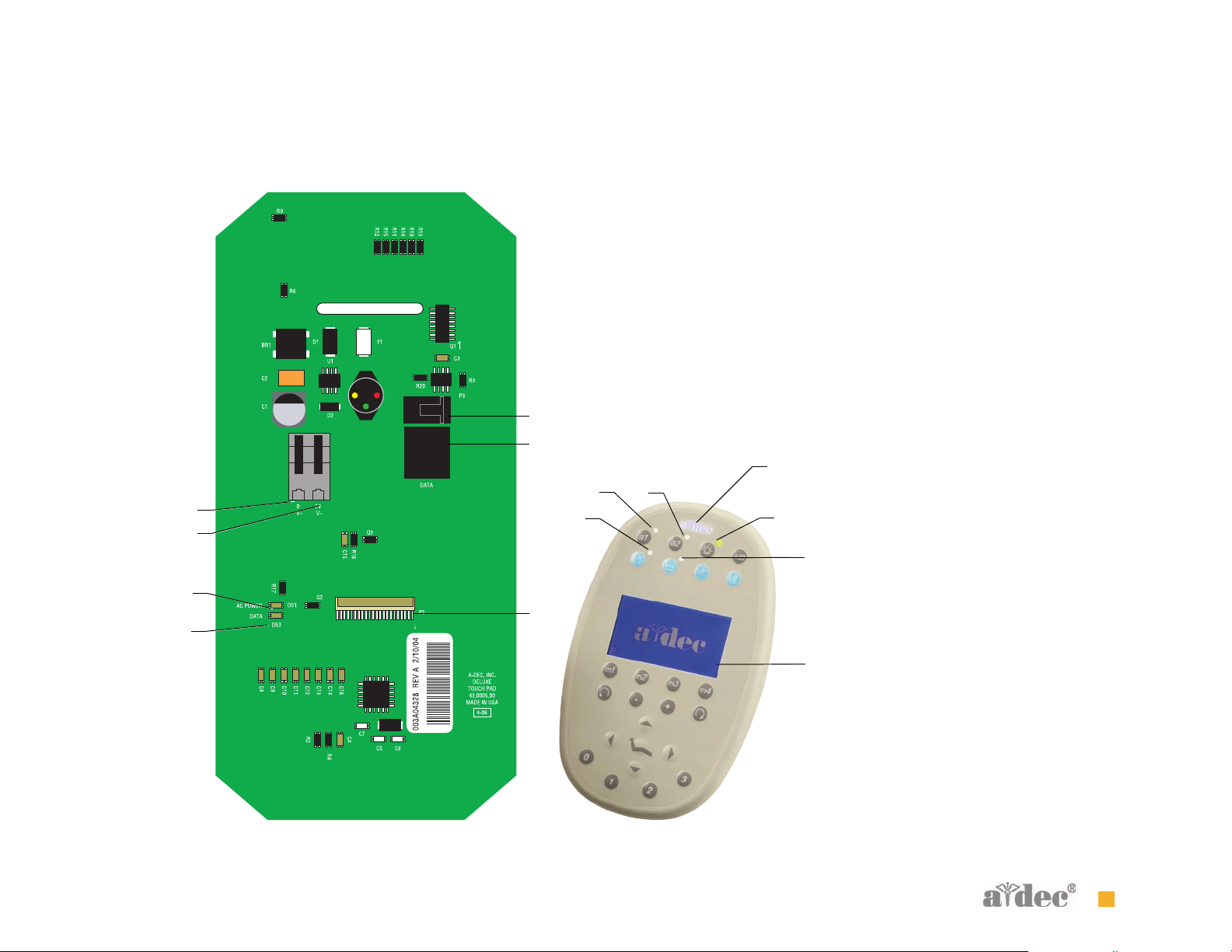
A-dec Service Guide, Vol. II Touchpad Circuit Board Components Deluxe Touchpad
8
6
2
9
10
4
5
11
13
12
1
7
3
14
85.0816.00 Rev B 2007-04 65
Page 77

A-dec Service Guide, Vol. II Touchpad Circuit Board Components Deluxe Touchpad
66 85.0816.00 Rev B 2007-04
Page 78

A-dec Service Guide, Vol. II
DELIVERY SYSTEMS
A-dec 500 delivery systems provide a variety of delivery options for
the doctor and the assistant. The delivery system regulates the air and
water used to operate the handpieces, syringes and accessories.
Delivery system options include:
• Front-mounted delivery
• Traditional (model 532) and Continenetal (model 533)
• Side mounted (model 542)
• 12 O’clock
• Duo Delivery (model 541)
• Assistant’s Instrumentation (model 545)
4
85.0816.00 Rev B 2007-04 67
Page 79

A-dec Service Guide, Vol. II Product Overview
P RODUCT OVERVIEW
The doctor’s side of the A-dec 500 system includes both the Traditional
®
(model 532) and Continental
mount monitor (model 531), and self-contained water system.
The A-dec 532 and 533 delivery systems have been designed to mount
only to the A-dec 511 chair and communicate with the entire A-dec 500
product line through the Data Communications System (DCS).
The A-dec 542 Side Delivery System is designed to mount to a wall or
to a Preference Collection
tray holder can be installed. When installed, the tray holder positions
over the control head.
The A-dec 500 12 O’clock system features two models. The A-dec
Model 541 and Model 545 are floor-mounted delivery systems that
install with a variety of Preference Collection
cabinets.
(model 533) delivery systems, the front-
®
or Preference Slimline cabinet. An optional
and Preference Slimline
This section of the A-dec Service Guide, Vol. II contains the electrical and
plumbing flow diagrams for the delivery systems, along with
illustrations of exploded parts, troubleshooting and adjustments for all
of the doctor’s side modules.
For information on service parts, see the Genuine A-dec Service Parts
Catalog, or contact A-dec customer service.
68 85.0816.00 Rev B 2007-04
Page 80

A-dec Service Guide, Vol. II
CHAIR-MOUNTED DELIVERY SYSTEMS
The A-dec 500 chair-mounted system features two models, the A-dec
Traditional (model 532) and Continental (model 533). Both models are
chair-mounted delivery systems that install on the A-dec 511 chair. The
A-dec 500 standard configuration for both Model 532 and 533 has:
• Balanced flexarm with air brake
• Four handpiece control block positions
• Control head with room to house integrated accessories
• Autoclavable saliva ejector
• Autoclavable syringe (option of warm water syringe)
• 2-liter self-contained water system with quick-disconnect
water bottle
• Standard multi-function touchpad (optional) or deluxe
multi-function touchpad (optional)
C HAIR- MOUNTED SYSTEM CONTENTS
Product Overview, page 70
Flow Diagrams, page 76
Leveling/Adjustments, page 78
Illustrated Parts Breakdown, page 81
85.0816.00 Rev B 2007-04 69
Page 81

A-dec Service Guide, Vol. II Product Overview (532/533) A-dec 500 Delivery System Components
P RODUCT OVERVIEW (532/533)
A-dec 500 Delivery System Components
The A-dec 500 delivery systems and front-mount monitor both mount to the A-dec 511 chair. This mounting structure provides left/right
capabilities for both the delivery system and the monitor.
Item Description
1 Delivery system cover
2 Delivery system front cover (533 only)
3Touchpad
4Brake handle
5Flexarm
6 Front-mount arm
7 Flexarm hub
8 Front-mount casting
70 85.0816.00 Rev B 2007-04
Page 82

A-dec Service Guide, Vol. II Product Overview (532/533) A-dec 500 Delivery System Components
Figure 37 Delivery system and front-mount arm components
2
1
3
4
8
5
7
6
85.0816.00 Rev B 2007-04 71
Page 83

A-dec Service Guide, Vol. II Product Overview (532/533) Covers
Covers
The delivery system covers are designed for easy access to control
components.
Delivery System Cover
To open the delivery system cover, lift up on the center tab on the back
of the delivery system cover and then, lift up the tabs on both sides of
the delivery system cover. To remove the cover, pinch the hinge
brackets at the cover base.
Delivery System Front Cover — Continental
To open the delivery system cover, move the whips forward and
remove the two screws holding the front cover in place. Open the front
cover carefully, until the lanyard is taut.
CAUTION Remove handpieces from the delivery system
before opening the delivery system front cover.
Figure 38 Open the Delivery System Cover and Front Covers
532/533
A
533 only
A
532 only
(A) Screw
72 85.0816.00 Rev B 2007-04
Page 84

A-dec Service Guide, Vol. II Product Overview (532/533) Whip Assembly
Whip Assembly
Part No: 77.0291.01
Adjust the whip return tension by placing the bail in two different
locations, A or B (see Figure 39).
You can remove the whip cover for easy handpiece tubing
replacement. To reinstall the whip cover, fully extend the whip and
attach the back starting at the ball end and work toward the handpiece
end.
Figure 39 Whip Assembly with Adjustable Bail Position
A
B
Attach Spring At (A) for Greater Tension or (B) for Lesser Tension
85.0816.00 Rev B 2007-04 73
Page 85

A-dec Service Guide, Vol. II Product Overview (532/533) Continental Tray Holder (533 only)
Continental Tray Holder (533 only)
Part No: 77.0294.01
Continental tray holders can be mounted on the left or right side below
the delivery system.
NOTE Standard delivery systems use the Traditional tray
holders. For information on Traditional tray holders refer to
the All Delivery section, page 154.
Figure 40 Continental Tray Holder Components
74 85.0816.00 Rev B 2007-04
Page 86

A-dec Service Guide, Vol. II Product Overview (532/533) Continental Tray Holder (533 only)
85.0816.00 Rev B 2007-04 75
Page 87

A-dec Service Guide, Vol. II Flow Diagram (532/533) Continental Tray Holder (533 only)
F LOW DIAGRAM (532/533)
This flow diagram details both electrical and plumbing information for servicing and troubleshooting A-dec 532 and 533 delivery systems. It is
located on the inside cover of the delivery system. This diagram includes the plumbing and wiring for the standard touchpad, deluxe touchpad,
camera, and electric micromotor.
76 85.0816.00 Rev B 2007-04
Page 88

A-dec Service Guide, Vol. II Flow Diagram (532/533) Continental Tray Holder (533 only)
Figure 41 A-dec 532 and 533 Flow Diagram
OPTIONAL WARM WATER SYRINGE
85.0816.00 Rev B 2007-04 77
Page 89

A-dec Service Guide, Vol. II Adjustments (532/533) Front Mount
A DJUSTMENTS (532/533)
Front Mount
Level Adjustment
1. Position all front-mount modules, (e.g., delivery system, flexarm,
tray holder assemblies) to align with the centerline of the chair.
2. Use the bubble level (if applicable) to determine when the correct
front mount adjustments have been made.
3. Loosen the stabilizing screws and flanged nuts.
4. Adjust the leveling cam for side-to-side leveling.
5. Use one of the leveling bolts to adjust the front-to-back leveling.
Assure both bolts are touching the casting when the delivery
system is level front-to-back.
6. Tighten the leveling cam securely.
7. Tighten the stabilizing screws until the screws make contact with
the casting when all of the front mount leveling adjustments have
been made. Do not overtighten.
NOTE You may need to lower the back to improve access.
8. Securely tighten the flanged nuts.
78 85.0816.00 Rev B 2007-04
Page 90

A-dec Service Guide, Vol. II Adjustments (532/533) Front Mount
Tension Adjustment
If the front-mount arm drifts, adjust the front-mount tension. To adjust
the front mount tension, tighten or loosen the rotation bolt connecting
the front-mount arm to the front-mount casting. Turning the rotation
bolt right increases the tension on the arm and left decreases
the tension.
Figure 42 Leveling and Adjusting the Front Mount Arm
1
2
3
4
5
6
Item Description
1 Leveling cam
2 Stabilizing screw, 1/4-20” x 2-1/4”
3 Flanged nuts
4 Leveling bolts
5Bubble level
6Rotation bolt
85.0816.00 Rev B 2007-04 79
Page 91

A-dec Service Guide, Vol. II Adjustments (532/533) Front-to-Back Leveling
Front-to-Back Leveling
1. Remove the flexarm front knuckle covers.
2. Position the delivery system in line with the flexarm.
3. Tighten or loosen the adjustment screw on the underside of the
front knuckle until the delivery system is level front-to-back.
4. Replace the covers.
Side-to-Side Leveling
Alternately tighten and loosen the two leveling screws on the
underside of the delivery system until it is level side-to-side. Tighten
both screws when level.
Figure 43 Level the Delivery System in Two Locations
80 85.0816.00 Rev B 2007-04
Page 92

A-dec Service Guide, Vol. II Illustrated Parts Breakdown Part Identification
I LLUSTRATED PARTS BREAKDOWN
This section contains illustrated parts breakdowns specific to the
Traditional (Model 532) and Continental (Model 533) chair mounted
delivery systems.
Part Identification
The conventions for the serviceable components tables are designed to
identify all parts and kits, including ones that are not for sale. Symbols
with reference notes are used.
Symbol Definition
†
No symbol Part is for sale
Indicates that the individual part is not available for
sale (these parts are typically part of a kit and/or
larger assembly that is for sale)
C HAIR MOUNTED DELIVERY IPB CONTENTS
Traditional Chair Mounted Delivery System (Model 532),
page 82
Continental Chair Mounted Delivery System (Model 533),
page 84
Delivery System — Upper Exploded (532 and 533), page 86
Traditional Holder Assembly (532), page 90
Continental Whip Assembly (533), page 92
Continental Tray Holder, page 94
85.0816.00 Rev B 2007-04 81
Page 93

A-dec Service Guide, Vol. II Illustrated Parts Breakdown Traditional Chair Mounted Delivery System (Model 532)
Traditional Chair Mounted Delivery System (Model 532)
Item Part Number Description
1 77.0056.01 Cover, top, control head
2 77.0240.00 Hinge link
3 001.033.00
4 002.135.00
5 77.0079.00 Cover, transition, Traditional
6 Traditional holders assembly
7 77.0147.00 Bracket, ancillary
8 77.0143.00 Top cover
9
10
11 77.0142.00 Cover, side, knuckle, RH
12 77.0289.00 Flexarm assembly
13
14 005.026.00
15 042.222.00 Ball stud
16 005.026.00
001.167.00 Screw, button head, socket, 6-32 x 3/8", stainless steel
77.0144.00
77.0144.00
†
†
Screw, socket head, 6-32 x 3/8
Screw, socket head, 10-32 x 1/2", stainless steel
Housing, flexarm (included in item 12)
Housing, flexarm (included in item 12)
Screw, button head socket, 1/4-20 x 3/4
Screw, 1/4-20 x 3/4
", patch button head
", stainless steel
"
82 85.0816.00 Rev B 2007-04
Page 94

A-dec Service Guide, Vol. II Illustrated Parts Breakdown Traditional Chair Mounted Delivery System (Model 532)
Figure 44 Traditional Chair Mounted Delivery System (Model 532)
10
12
11
13
10
AC
WC EX AC WCEX
1234
9
7
OIL OIL OIL OILDA
AC WC
U
S
P
a
t
. 5
EX AC WC EX
,
2
0
DA DA DA
1
,
8
9
9
8
6
5
4
3
2
1
14
11
16
15
85.0816.00 Rev B 2007-04 83
Page 95

A-dec Service Guide, Vol. II Illustrated Parts Breakdown Continental Chair Mounted Delivery System (Model 533)
Continental Chair Mounted Delivery System (Model 533)
Item Part Number Description
1 042.222.00 Ball stud
2 77.0056.01 Cover, top, control head
3 77.0240.00 Hinge link
4 001.033.00
5 77.0147.00 Bracket, ancillary
6 77.0143.00 Top cover
7 001.167.00
8 77.0141.00 Cover, side, knuckle, LH
9
10 77.0142.00 Cover, side, knuckle, RH
11 77.0289.00 Flexarm assembly
12 77.0070.00 Pad, instrument, Continental
13 77.0291.01 Whip assembly
14 005.026.00
15 77.0065.00
77.0144.00
†
Screw, socket head, 6-32 x 3/8
Screw, button head, socket, 6-32 x 3/8
Housing, flexarm (included in item 11)
Screw, button head socket, 1/4-20 x 3/4
Cover, top, Continental
", stainless steel
", stainless steel
"
84 85.0816.00 Rev B 2007-04
Page 96

A-dec Service Guide, Vol. II Illustrated Parts Breakdown Continental Chair Mounted Delivery System (Model 533)
Figure 45 Continental Chair Mounted Delivery System (Model 533)
2
6
7
8
9
10
11
8
3
1
4
US Pat. 5,201,899
OIL OIL OIL
AC
WC
EXAC
WC EX ACWCEX AC
5
234
1
OILDA DA DA DA
WCEX
15
12
10
13
14
85.0816.00 Rev B 2007-04 85
Page 97

A-dec Service Guide, Vol. II Illustrated Parts Breakdown Delivery System — Upper Exploded (532 and 533)
Delivery System — Upper Exploded (532 and 533)
Item Part Number Description
1 90.1076.00 Circuit board assembly kit
2 001.034.00
3 006.002.00 Grounding nut
4 77.0384.00 Tray
5 006.009.00
6 002.130.00
7 90.1110.00 Oil collect or assembly
8 025.115.00 Standoff, lock clip, .75 ID x .5 HT
9 001.034.00
10 042.634.00 Ball spring
11 77.0150.00 Hoe plug, touchpad
12 90.1082.00 Circuit board stand-off, package of 5 (available in circuit board kit P/N 90.1076.00)
13 38.1776.00 Control block assembly
14 33.0168.00 Valve assembly, 4-way
15 002.135.00
16 33.0048.05 Valve, toggle, 3-way
17 005.161.00
18 38.1810.00 Relay assembly, water coolant, air actuated (standard touchpad or not touchpad only)
19 77.0152.00 Clamp, touchpad holder
20 002.112.00
21 99.0667.00 Valve assembly, handle
22 90.1133.00 Kit, standard to deluxe touchpad
23 77.0297.00 Kit, standard touchpad
24 43.0057.00 Manifold assembly, solenoid, dual (deluxe touchpad only)
Screw, socket head, 6-32 x 1/4
Hex nut, 15/32-32 x 9/16
Screw, 10-32 x 3/8
Screw, 6-32 x 1/4
Screw, 10-32 x 1/2
Screw, 6-32 x 5/8", socket head, stainless steel - with washer
Screw, 10-32 x 7/8
", socket head
", socket head
", socket head, stainless steel
", socket head
"
" x 3/32"
86 85.0816.00 Rev B 2007-04
Page 98

A-dec Service Guide, Vol. II Illustrated Parts Breakdown Delivery System — Upper Exploded (532 and 533)
Figure 46 Delivery System - Upper Exploded (532 and 533)
1
2
3
4
5
6
7
8
9
10
11
14
15
16
15
12
13
17
18
15
19
17
20
21
22
23
15
24
85.0816.00 Rev B 2007-04 87
Page 99

A-dec Service Guide, Vol. II Illustrated Parts Breakdown Delivery System — Lower Exploded (532 and 533)
Delivery System — Lower Exploded (532 and 533)
Item Part Number Description
1 002.117.00 Screw, 6/16-18 x 3/4" button head socket
2 004.009.00 Washer, split lock, steel plated, .312 ID
3 77.0265.00 Plate hub mount
4 016.133.00 Bearing, thrust, 63mm
5 013.085.00 Spring, compression, .460 OD x .625
6 77.0247.00 Brake pad, control head
7 77.0160.00 Hub, pivot, control head
8 77.0104.01 Brake handle assembly
9 77.0075.00 Plate, guide, tubing, control head
10 001.088.00 Screw, socket head, 10-32 x 5/8", stainless steel
11 77.0266.00 Bar, friction adjust, control head
12 002.085.00
13 77.0057.01 Cover, lower, control head
14 77.0424.00 Plug, hole, brake handle
Screw, flat head socket, 1/4-20 x 1/2
"
88 85.0816.00 Rev B 2007-04
Page 100

A-dec Service Guide, Vol. II Illustrated Parts Breakdown Delivery System — Lower Exploded (532 and 533)
Figure 47 Delivery System - Lower Exploded (532 and 533)
7
8
9
4
5
6
11
12
10
3
4
1
2
8
13
14
85.0816.00 Rev B 2007-04 89
 Loading...