

Page 1
85.0816.00 Rev A 2004-11 (PCA 04002.12) Page 89
A-dec Service Guide, Vol. II Support Side
This section of the service guide contains service information for the A-dec 500
Support Side System. The support side system provides modules for assistant and
patient use. These modules allow easy access to tools and quick storage.
This section provides information related to servicing, maintenance, and adjustments.
Detail on how to service the support side and troubleshoot specific problems is
presented. For information on service parts, see the Genuine A-dec Service Parts Catalog
or contact A-dec customer service.
Page 2
Page 90 85.0816.00 Rev A 2004-11 (PCA 04002.12)
Support Side Modules A-dec Service Guide, Vol. II
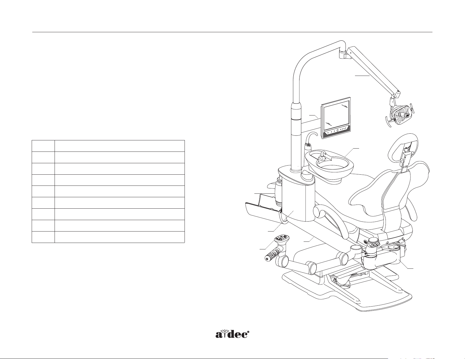
How to Identify Support Side Modules
The A-dec 500 support side system includes; the A-dec 551 assistant’s
instrumentation, the A-dec 561 cuspidor and monitor mount, the A-dec 571
dental light, and the amalgam separator housing.
Support side modules can be rotated at 90° right or left of the chair by
loosening the locking knob on the support link.
The A-dec 571 dental lights is addressed in the Dental Light section of this
service guide.
Item # Description
1
Support link
2
Lower support arm
3
Assistant’s instrumentation and touchpad
4
Cuspidor
5
Support center
6
Water bottle
7
Monitor mount
8
Dental light
8
7
4
6
5
3
2
1
Figure 60. Identifying the support side modules.
Page 3
85.0816.00 Rev A 2004-11 (PCA 04002.12) Page 91
A-dec Service Guide, Vol. II Support Side Components
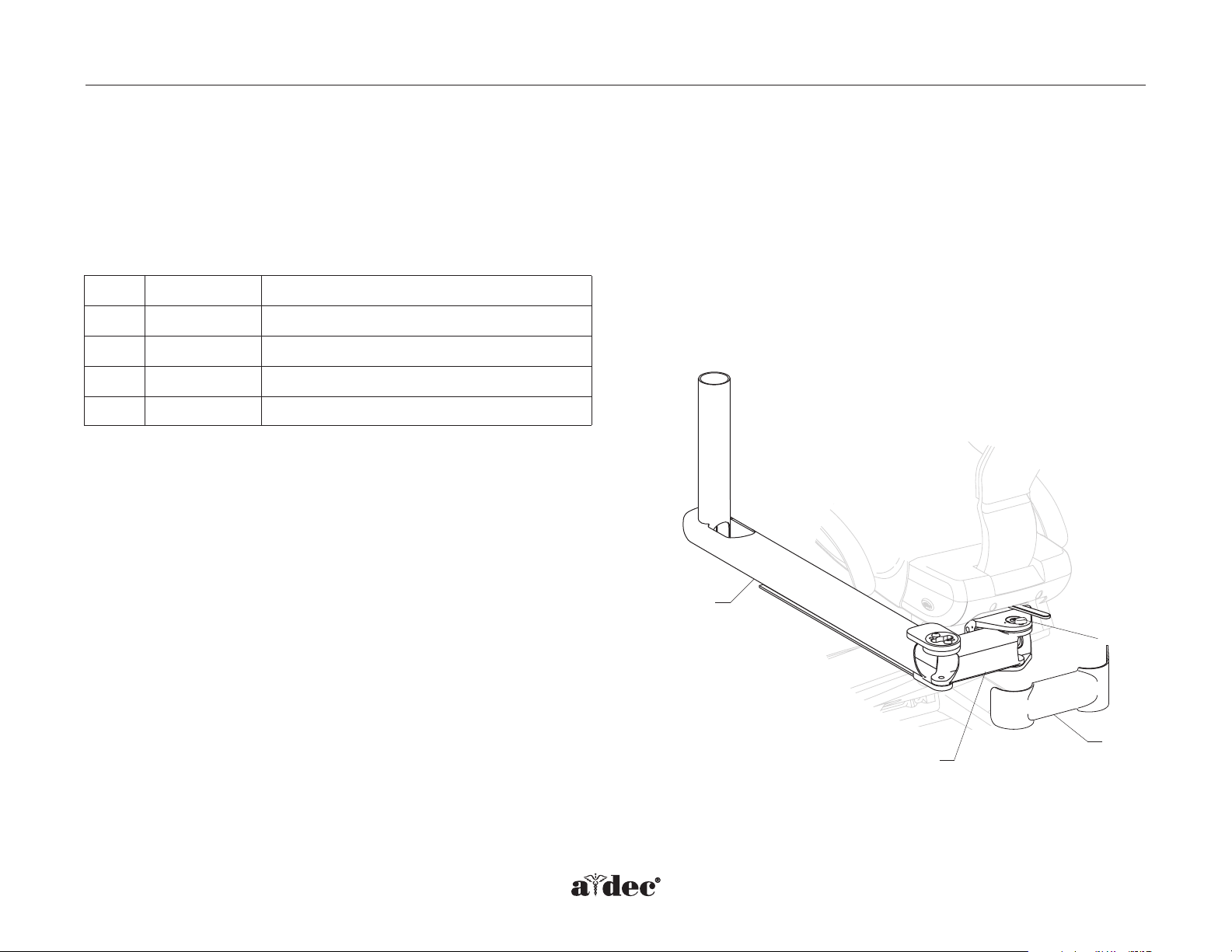
How to Identify Support Side Components
Lower Support Arm
The support link is the hub for all modules that will mount off the back of the chair.The support system requires both a support link and a lower
support arm. Assistant’s instrumentation requires only a support link.
Item #
Part Number
Description
1
77.0373.00
Locking knob
2
77.0278.00
Support link
3
77.0286.00
Lower support arm
4
77.0380.00
Support link cover (90.1096.00 support link cover kit)
4
3
1
2
Figure 61. Identifying the support link and lower support arm.
Page 4

Page 92 85.0816.00 Rev A 2004-11 (PCA 04002.12)
Support Side Components A-dec Service Guide, Vol. II
Support Link
(P/N 77.0278.00)
The support link mounts to the back of the chair with four bolts. A leveling bar, which levels the support link and lower support arm, is mounted
to the back of the chair using two dowel pins.
Item #
Part Number
Description
1
77.0278.00
Support link
2
001.094.00
Mounting bolt
3
77.0239.00
Leveling bar
4
006.148.00
Locking nut
5
77.0373.00
Locking knob
6
77.0374.00 Small bearing cap cover
7
77.0376.00 Support link cover, left
8
77.0377.00 Support link cover, right
9
002.051.00 Socket head screw, 10-32 X 1/2
10
004.240.00 Washer, 1/2"
1
2
8
3
7
6
5
4
Figure 62. Identifying support link components.
9
10
Page 5

85.0816.00 Rev A 2004-11 (PCA 04002.12) Page 93
A-dec Service Guide, Vol. II Support Side Adjustments
How to Level the Support Link and Lower Support Arm
Equipment Positioning
Support side modules may require leveling. Level the support link and lower support arm by adjusting the leveling bolt in the support link
assembly. Note where the support system will be positioned before leveling.
•Level the equipment with the modules positioned 90° to the back of the chair, if the support
system will be used both in a left and right positions.
•Level the equipment with the modules in a normal operating position, if the support system
will be used in a stationary position.
90°
0°
Figure 63. Level equipment with modules
at 90° to the back of the chair for left and
right positioning.
Page 6

Page 94 85.0816.00 Rev A 2004-11 (PCA 04002.12)
Support Side Leveling A-dec Service Guide, Vol. II
Support Link and Lower Support Arm Leveling
NOTE: The stop switch assembly may have to be removed. Be sure to power off the
chair and disconnect it from its power source before replacing the stop switch.
1. Loosen the four mounting bolts on the support link.
2. Loosen the locking nut.
3. Place a level parallel on the lower support arm, and adjust the leveling bar bolt until the
lower support arm is level.
4. Tighten the locking nut against the leveling bar.
5. Tighten the four mounting bolts as tight as possible (65 ft lb of torque).
Item # Description
1
Stop switch assembly
2
Support link
3
Mounting bolts
4
Leveling bar
5
Locking nut
Figure 65. Remove the limit switch assembly.
Figure 64. Tighten the locking nut against the
leveling bar.
2
1
3
4
5
Page 7

85.0816.00 Rev A 2004-11 (PCA 04002.12) Page 95
A-dec Service Guide, Vol. II Stop Switch
How the Stop Switch Operates
The support side stop switch stops chair movement immediately when pressed. Be sure to power off the chair and disconnect it from its power
source before replacing the stop switch.
Bump-Up Feature
The stop switch triggers the chair to move upwards, approximately one inch, if it was moving down when the switch was activated.
4
3
8
Item #
Part Number
Description
1
77.0354.00*
Tubing guide, short
2
77.0357.00*
Actuator plate
3
002.140.00
Screws, patch button head
4
77.0361.00
Stand-off screw
5
43.0087.00 Limit switch kit with (2) 001.219.00 socket head
screws, and 023.123.00 stop switch actuator barb
6
024.141.00
Tubing, 1/4" OD, D-Surf, 4"
7
025.002.01
Cable tie, pkg 10
8
77.0360.00 Stop switch tubing (long)
77.0359.00 Stop switch tubing (short) for assistant’s
instrumentation only
1
2
4
5
6
7
Figure 66. Identifying the support side stop switch components.
* Item not for sale.
Page 8

Page 96 85.0816.00 Rev A 2004-11 (PCA 04002.12)
Electrical Diagram A-dec Service Guide, Vol. II
Support Side Stop Switch Electrical Diagram
Chair stop plate
Stop switch
assembly
Chair stop
switch
Jumper
Chair base
stop switch
wires
Chair circuit board
 Loading...